All articles published by MDPI are made immediately available worldwide under an open access license. No special
permission is required to reuse all or part of the article published by MDPI, including figures and tables. For
articles published under an open access Creative Common CC BY license, any part of the article may be reused without
permission provided that the original article is clearly cited. For more information, please refer to
https://www.mdpi.com/openaccess.
Feature papers represent the most advanced research with significant potential for high impact in the field. A Feature
Paper should be a substantial original Article that involves several techniques or approaches, provides an outlook for
future research directions and describes possible research applications.
Feature papers are submitted upon individual invitation or recommendation by the scientific editors and must receive
positive feedback from the reviewers.
Editor’s Choice articles are based on recommendations by the scientific editors of MDPI journals from around the world.
Editors select a small number of articles recently published in the journal that they believe will be particularly
interesting to readers, or important in the respective research area. The aim is to provide a snapshot of some of the
most exciting work published in the various research areas of the journal.
Airborne scatterometer capability depends on not only the device’s technical characteristics but also the scheme used for surface observations. Typically, a rotating-beam scatterometer uses a circular scheme for sampling normalized radar cross-sections (NRCS) at wind measurements over the sea. Here, we investigate wind retrieval using an updated semicircular scheme, providing the NRCS sampling at various combinations of incidence angles within the range 30° to 60°. The effectiveness of the wind retrieval using our semicircular sampling scheme was evaluated using Monte Carlo simulations, and we then developed corresponding wind algorithms that used a geophysical model function (GMF). As a result of the study, we found that a semicircular sampling scheme is well suited for wind retrieval over the sea using a rotating-beam scatterometer. We showed that a semicircular scheme can provide wind retrieval accuracies similar to those achievable with a conventional circular scheme, although the semicircular scheme requires approximately three times the number of NRCS samples integrated in each azimuth sector. Most importantly, however, the semicircular scheme enabled a maximum altitude for wind retrieval of twice the height possible with a circular scheme. In this study, we also demonstrate that the wind speed accuracy tends to increase with an increase in the incidence angle and similarly for the wind direction accuracy. Nonetheless, we then show that the simultaneous use of the NRCS sampling scheme at several incidence angles can increase the wind retrieval accuracy, especially when three or four incidence angles are used. The obtained results can be used to enhance airborne scatterometers and multimode radars operated in a scatterometer mode, including airborne high-altitude conical scanning radars, and can be applied to new remote sensing systems’ development.
Depending on the measurement geometry of airborne scatterometers and multimode radars with a scatterometer mode, various NRCS sampling schemes can be applied to measurements [1]. The radars can be equipped with a fixed-beam [2,3,4,5,6], scanning [7,8,9], or rotating-beam antenna [10,11,12,13,14,15,16,17].
Radars using only a single fixed-beam antenna perform circular NRCS sampling in circular flight [3,4,5,18], as exemplified, for instance, by Masuko et al.’s airborne microwave scatterometer/radiometer system [3]. Radars equipped with a multiple fixed-beam antenna provide NRCS sampling in rectilinear flight, from the constant azimuth directions relative to the aircraft’s course [5,19,20], e.g., a Doppler navigation system operated in the scatterometer mode [21,22]. The measurements are all performed at the same incidence angle.
On the other hand, radars with a scanning antenna perform measurements in rectilinear flight. Depending on their scanning geometry, they provide NRCS sampling by changing azimuth directions at properly varying incidence angles as the beam scans in the same inclined plane (e.g., in the airborne precipitation radar APR-2 case [7,23] or the airborne rain mapping radar ARMAR case [24]), as well as at the same incidence angle, e.g., in the case of airborne weather radar when it is operated in a ground mapping mode as a scatterometer [25,26].
Similarly, radars equipped with a rotating-beam antenna also perform measurements in rectilinear flight. Depending on their single-beam or multibeam geometry, they can perform NRCS circular sampling at a single incidence angle, e.g., in the C-band scatterometer C-SCAT case [27], or the Doppler scatterometer DopplerScatt case [28], as well as simultaneously at several constant incidence angles, e.g., in the imaging wind and rain airborne profiler IWRAP case [12] or in the case of the high-altitude imaging wind and rain airborne profiler HIWRAP [29].
Recently, we considered sea wind measurements in rectilinear flight with an airborne scatterometer with a rotating-beam antenna mounted both under [17] and over [16] the fuselage. A whole 360° azimuth circular scheme for NRCS sampling at single or several constant incidence angles was evaluated for wind vector retrieval over the sea [17]. Our study showed that simultaneous NRCS sampling at several neighboring incidence angles provides a better accuracy for wind vector estimation compared to NRCS sampling at a single incidence angle only. Unfortunately, wind retrieval using a circular scheme for NRCS sampling at several incidence angles decreased the maximum altitude of the wind retrieval method’s usability compared to sampling NRCS at a single incidence angle.
We also investigated the possibilities for increasing the maximum altitude of wind retrieval by an airborne scatterometer that has a rotating-beam antenna and uses semicircular NRCS sampling instead of the usual circular scheme [30]. A single incidence angle was considered. The application of the semicircular NRCS sampling scheme allowed for the maximum altitude of the wind estimation method to be doubled compared to the circular scheme. However, to provide equivalent accuracies for wind retrieval using the semicircular scheme, the number of NRCS samples integrated in each azimuth sector had to be tripled compared to the circular scheme.
In this context, in this paper we combined both of these approaches and analyzed the feasibility of simultaneous NRCS sampling at several neighboring incidence angles using our semicircular scheme. The aim was to optimize NRCS sampling in order to provide better wind retrieval accuracies and higher maximum altitudes for the method’s applicability for an airborne scatterometer with a rotating-beam antenna.
2. Materials and Methods
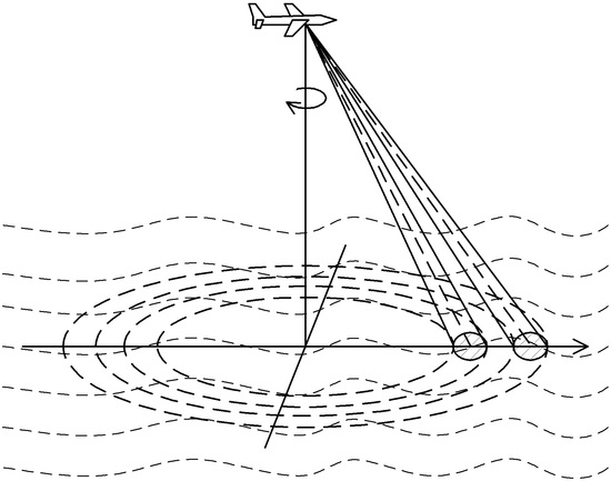
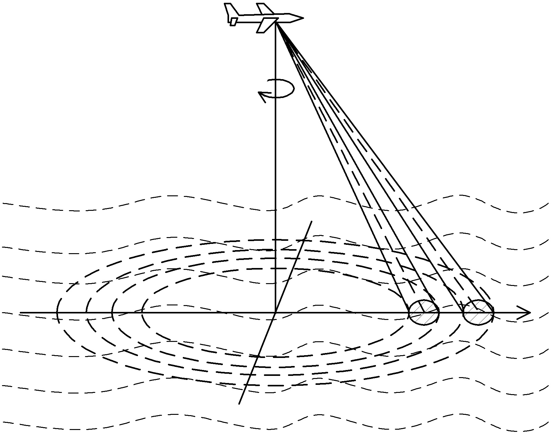
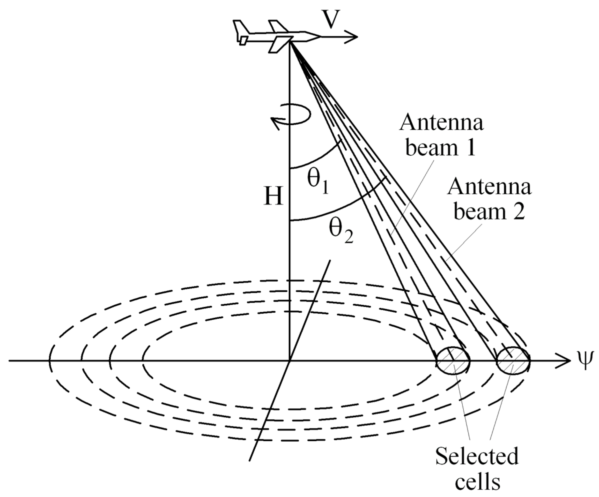
Several neighboring incidence angles’ simultaneous sampling of NRCSs can be performed using an airborne scatterometer equipped with a rotating antenna that has a fan-beam or multibeam geometry [1,31]. These geometries allow for simultaneous NRCS sampling from the same azimuth direction, as selected cells are located in the same vertical plane [17]. For example, the geometry of a scatterometer with a rotating two-beam antenna is presented in Figure 1.
The antenna’s rotation allows for NRCS sampling within an appropriate azimuth circle. The resulting NRCS curve consists of N azimuth sectors observed with an appropriate 5° or 10° azimuth step, providing an appropriate width of the azimuth sector Δαs, which satisfies a narrow antenna beam’s conditions (in the azimuth plane), having an appropriate angular width of each azimuth sector up to 15–20° [32,33]. Applying an appropriate geophysical model function (GMF), the speed of wind and its direction are also retrieved from the measured NRCS curve, as the GMF is an empirical or analytic relationship between the NRCS and the wind speed and incidence and azimuth angles, as well as the radar wavelength, transmit and receive polarization, and sometimes other parameters [31].
GMFs are derived from temporally and spatially collocated airborne, spaceborne, ship, tower, and buoy measurements of the NRCS and wind vector. One of the widely used forms of GMFs at medium incidence angles is as follows [34]:
where is the NRCS dependent from the wind speed U at a 10 m height over water, the incidence angle θ, and azimuth angle α measured from the upwind direction; , , and are the Fourier terms dependent on the wind speed and incidence angle, where , , and ; and , , , , , and are the coefficients dependent on the incidence angle. In fact, the term equals the azimuthally averaged NRCS, describes the upwind–downwind asymmetry, and represents the upwind–crosswind anisotropy. The detailed procedures to obtain these terms from NRCS in the upwind, downwind, and crosswind directions have been presented elsewhere [35]. For example, for the horizontal transmit and receive polarization, the GMF coefficients at the Ku-band are as follows [36]:
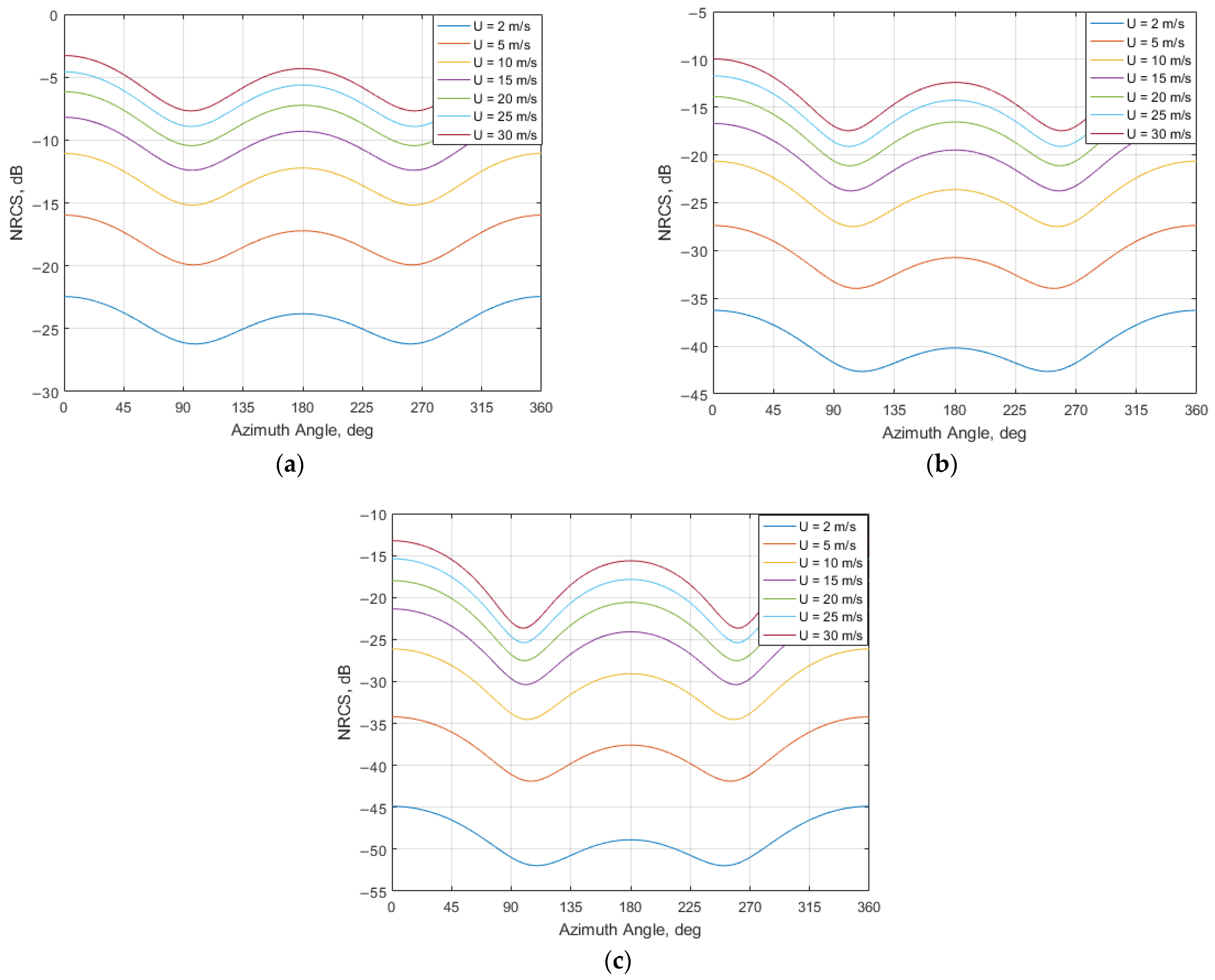
Examples of Ku-band GMF azimuthal curves for the horizontal transmit and receive polarization for wind speeds of 2, 5, 10, 15, 20, 25, and 30 m/s at the incidence angles of 30°, 45°, and 60° are shown in Appendix A (Figure A1a–c, respectively).
From Equation (1) and Figure A1a–c, we can see that the NRCS azimuth curve has two maxima and two minima. The principal maximum is located in the upwind direction. The second maximum corresponds to the downwind direction, and the two minima are in the crosswind directions displaced slightly towards the second maximum direction. With an increase in the incidence angle, the difference between the two maxima and the difference between the maxima and minima become so significant that this feature can be used for the retrieval of the wind direction over the water. The horizontal transmit and receive polarization is used as it provides greater upwind/downwind differences in the NRCS values of a GMF, especially at medium incidence angles, than the vertical transmit and receive polarization [2,3], and so it allows for the more precise retrieval of the wind direction.
Let a GMF be presented in the form of Equation (1). Then, in the case of circular NRCS sampling using an airborne scatterometer with a rotating antenna at a single incidence angle, wind vector retrieval is performed by solving the following system of N equations [16,37]:
where , and ; is the measured NRCS sample corresponding to i-th azimuth sector, and ψi is the direction of the i-th azimuth sector counted from the aircraft’s course ψ (measured clockwise from the north).
Consequently, for wind vector estimation in the case of circular NRCS sampling simultaneously at several incidence angles, the following system of equations was presented in previous research [17]:
where , and K is the number of observed incidence angles; is the measured NRCS sample at the respective incidence angle number j and azimuth sector number i.
Equations (3) and (4) provide the upwind direction, so the result needs to be converted to the measured wind direction ψw. The conversion is performed as follows [38]:
Our previous evaluation of sea wind measurements with a circular NRCS sampling scheme, in the cases of single and several incidence angles, proved that wind retrieval accuracies can be increased if several incidence angles are used simultaneously [17]. The NRCS sampling scheme also predetermines the wind retrieval method’s maximum altitude. The circular scheme of NRCS sampling needs a whole 360° azimuth observation of the water surface. The wind and wave conditions in the observed area need to be identical in all of its parts to perform the wind retrieval algorithm based on Equations (3) or (4). Typically, the wind and wave conditions are assumed to be effectively identical in an area with dimensions not exceeding 15–20 km. For example, the method’s applicable maximum altitudes for wind retrieval with a circular NRCS sampling scheme at a single incidence angle are approximately 17.3 km and 5.77 km at 30° and 60° incidence angles, respectively [17].
Recently, we suggested using another NRCS sampling scheme based on semicircular observations to increase the maximum altitude suitable for the wind retrieval method [30]. The whole 360° azimuth observation swath is divided into left and right halves (left-side and right-side semicircular schemes) relative to the aircraft’s course (ground track). This previous investigation was performed for the case of a single incidence angle and demonstrated that the semicircular scheme for NRCS sampling is also feasible for sea wind vector measurements. It allows for doubling the wind retrieval method’s maximum altitude while still achieving wind measurement accuracies similar to the accuracies provided by the circular NRCS sampling scheme, but this requires integrating triple the number of NRCS samples for each azimuth sector [30].
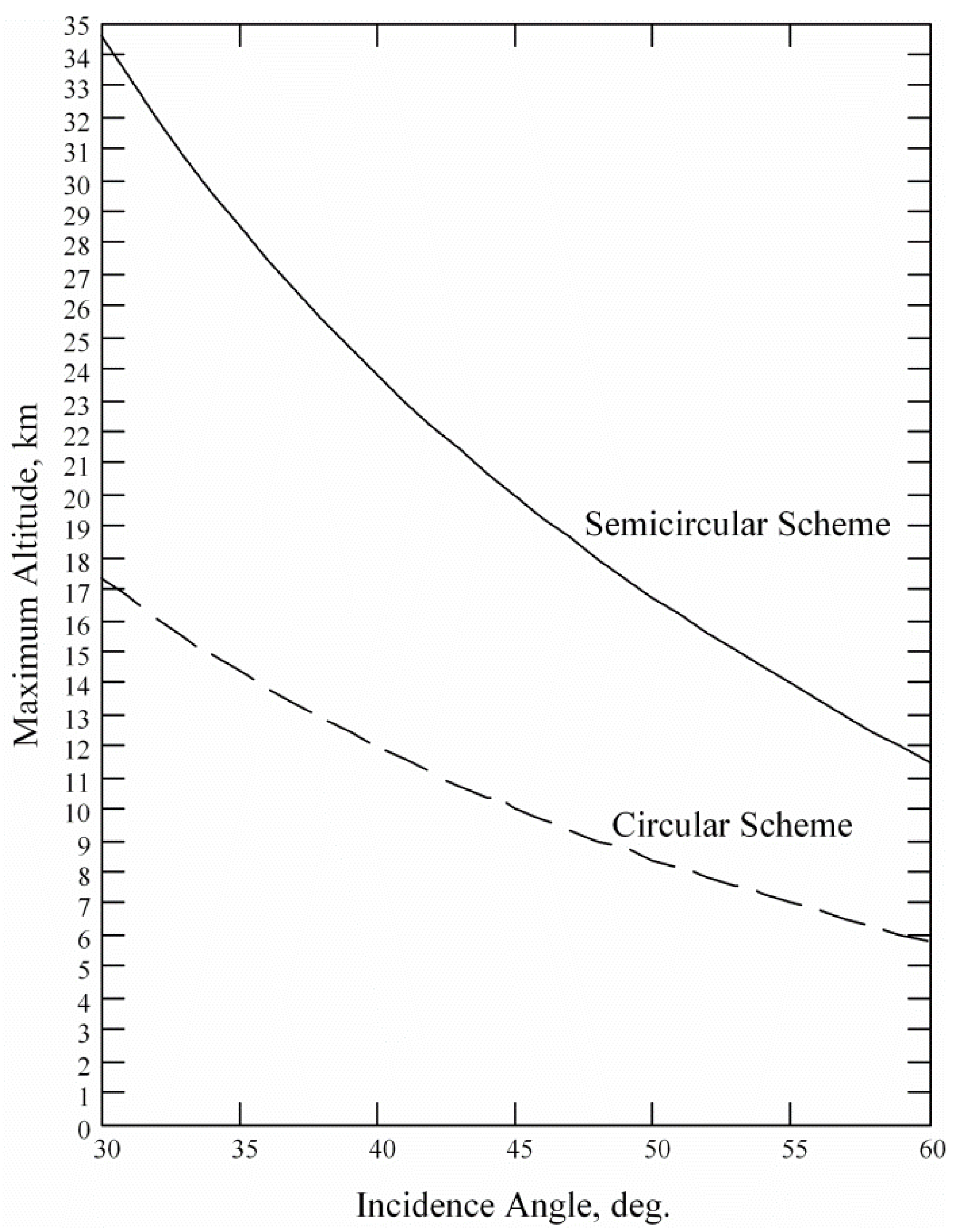
The gain of the semicircular NRCS sampling scheme in comparison with the circular NRCS sampling scheme in providing the maximum altitude of the wind retrieval method’s applicability can be seen in Figure 2.
As the ground strip of the semicircular NRCS sampling scheme is half as wide as the ground strip of the circular NRCS sampling scheme, the maximum altitude of the method’s applicability is doubled in the semicircular NRCS sampling scheme compared to the circular NRCS sampling scheme.
Here, we explore the idea that a further improvement in wind retrieval accuracies with semicircular NRCS sampling can be achieved by using NRCS samples obtained in the same vertical plane simultaneously at several incidence angles, instead of the single incidence angle used previously [30]. In this new approach, the system of equations for wind retrieval with the right-side semicircular scheme, simultaneously at several incidence angles, can be written as follows, halving the number of azimuth sectors from Equation set (4) for circular sampling:
Thus, in the case of an airborne rotating-antenna scatterometer, the use of the semicircular NRCS sampling scheme along with NRCS sampling simultaneously at several incidence angles can be applied to wind vector recovery during a flight over the sea.
3. Results and Discussion
To evaluate the potential of wind retrieval with a semicircular NRCS sampling scheme in the case of simultaneous observation at several incidence angles, we conducted Monte Carlo simulations. The simulations of the wind retrieval were performed using Equation set (6) above, a Rayleigh power (exponential) distribution, and a GMF, as per Equation (1), with the Ku-band GMF coefficients for the horizontal transmit and receive polarization using Equation (2).
For the considered semicircular NRCS sampling scheme, the procedure for wind retrieval from the measured azimuth NRCS consisted of solving Equation set (6) using a searching procedure within the ranges of the values of possible solutions to find the wind speed and upwind direction, which was then converted into the (navigational) wind direction using Equation (5).
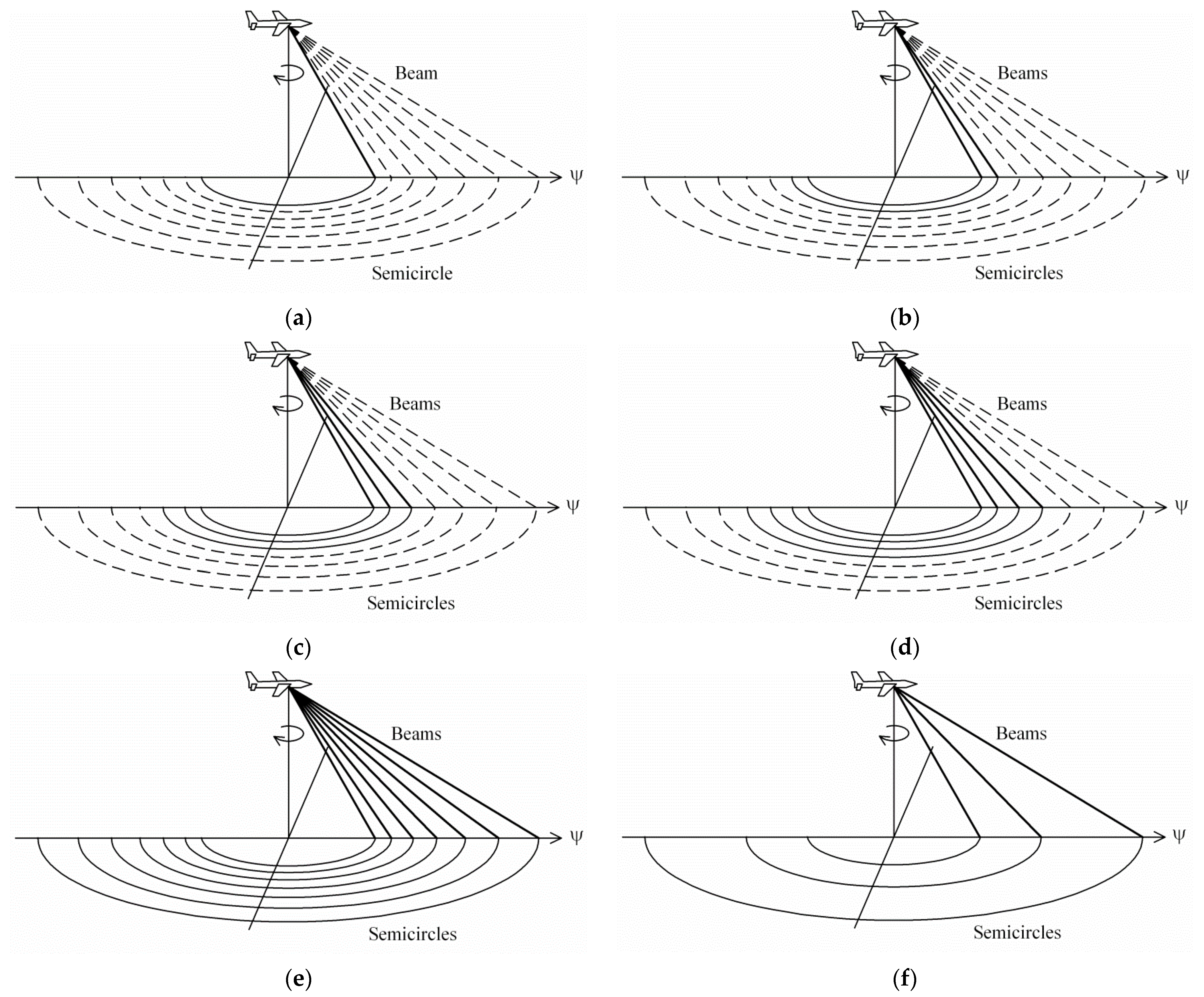
To compare the wind retrieval results obtained for the semicircular NRCS sampling scheme with several incidence angles to our earlier results for a circular scheme [17], we considered the same incidence angles of interest, 30°, 35°, 40°, 45°, 50°, 55°, and 60°, and the same 2–30 m/s range of wind speeds. Schematically, the semicircular observation with the considered incidence angle combinations’ geometries within the right-side semicircular scheme are presented in Figure 3.
An azimuth sectors’ width of 5° was assumed for the azimuth NRCS curves, and so the semicircular right-side NRCS curve (azimuths from 0° to 180°) was divided for N = 37 azimuth sectors. In the earlier experiments, the circular NRCS curve (azimuths from 0° to 355°) was divided for N = 72 azimuth sectors [17].
For each azimuth sector, 261 “measured” NRCSs were generated for the semicircular NRCS sampling scheme using the Equation (1) GMF with the coefficients from Equation set (2) and taking into account the random NRCS variations and instrument noise. This number of integrated samples was chosen for the simulations to reach wind retrieval accuracies similar to the case of the circular NRCS sampling scheme when only 87 samples were integrated in the azimuth sector. This is needed since the semicircular NRCS sampling scheme uses only half the number of azimuth sectors than the circular one, which could consequently lead to an increase in wind recovery errors and even wind direction ambiguities.
The retrieval of the wind direction using a scatterometer, especially a satellite scatterometer providing NRCS sampling from several azimuth directions, and also at different incidence angles, can produce ambiguous results [39,40]. As it is desirable to avoid ambiguities, or at least reduce the possibility of their appearance, we mainly analyzed the maximum errors to demonstrate that the wind retrieval method also provides an unambiguous estimation of the wind direction.
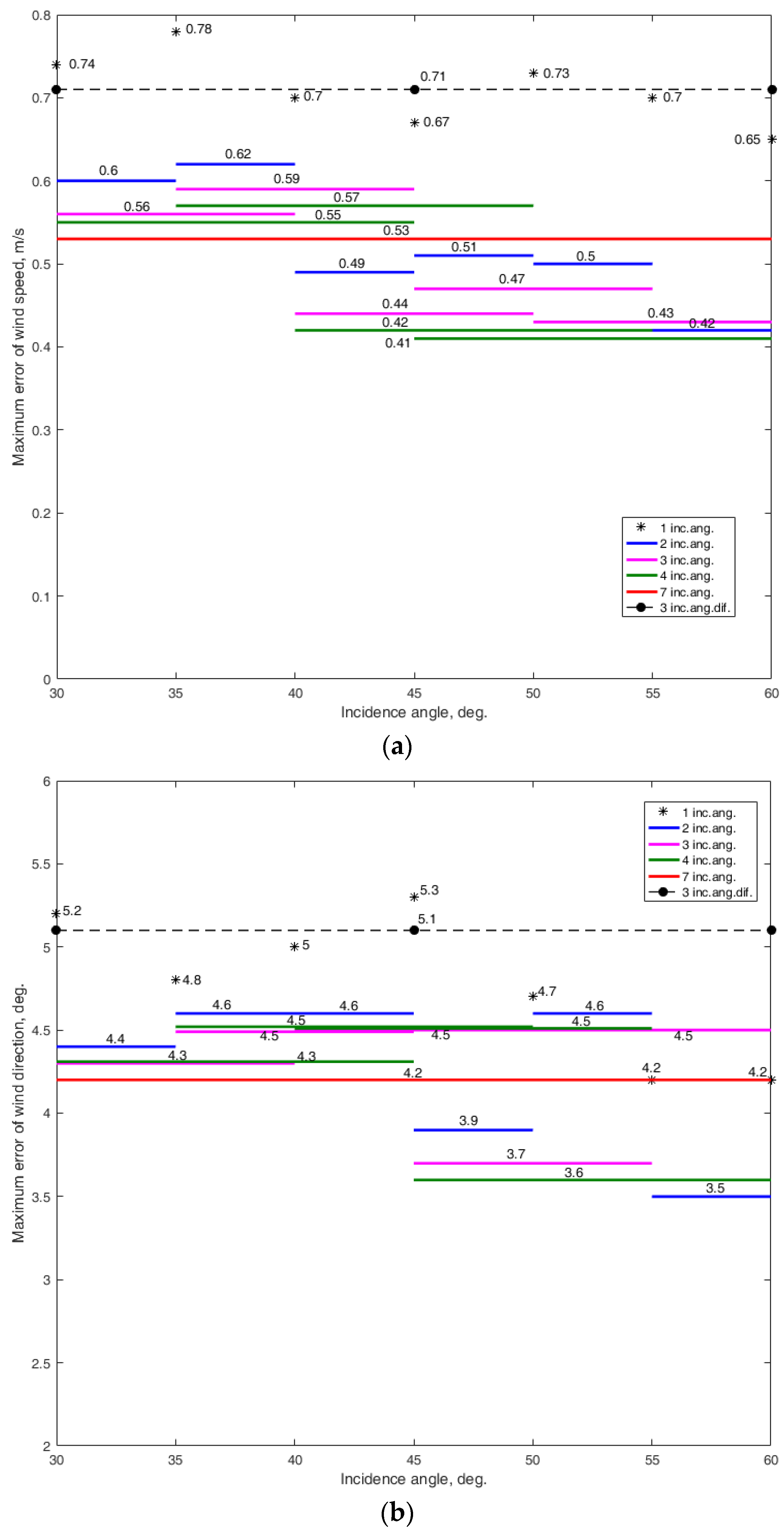
The simulations were completed assuming 0.2 dB instrument noise. Thirty independent trials were performed for each combination of the wind speed and azimuth angle for each given incidence angle. The semicircular NRCS sampling scheme’s simulation results appear in full in the appendixes, and the results are summarized in Figure 4. They show that the maximum wind speed error tends to decrease when the incidence angle increases, as does the maximum error in the wind direction.
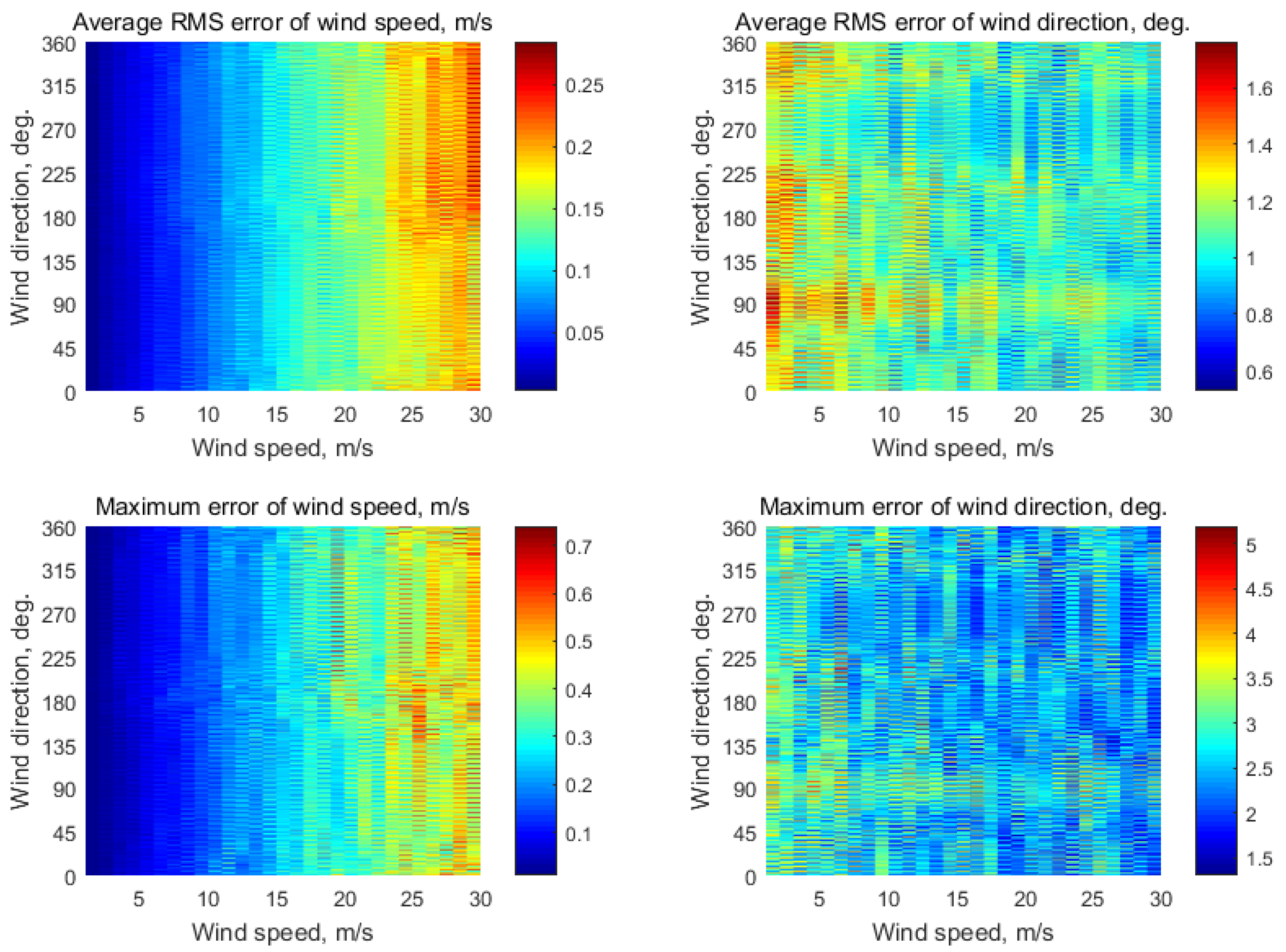
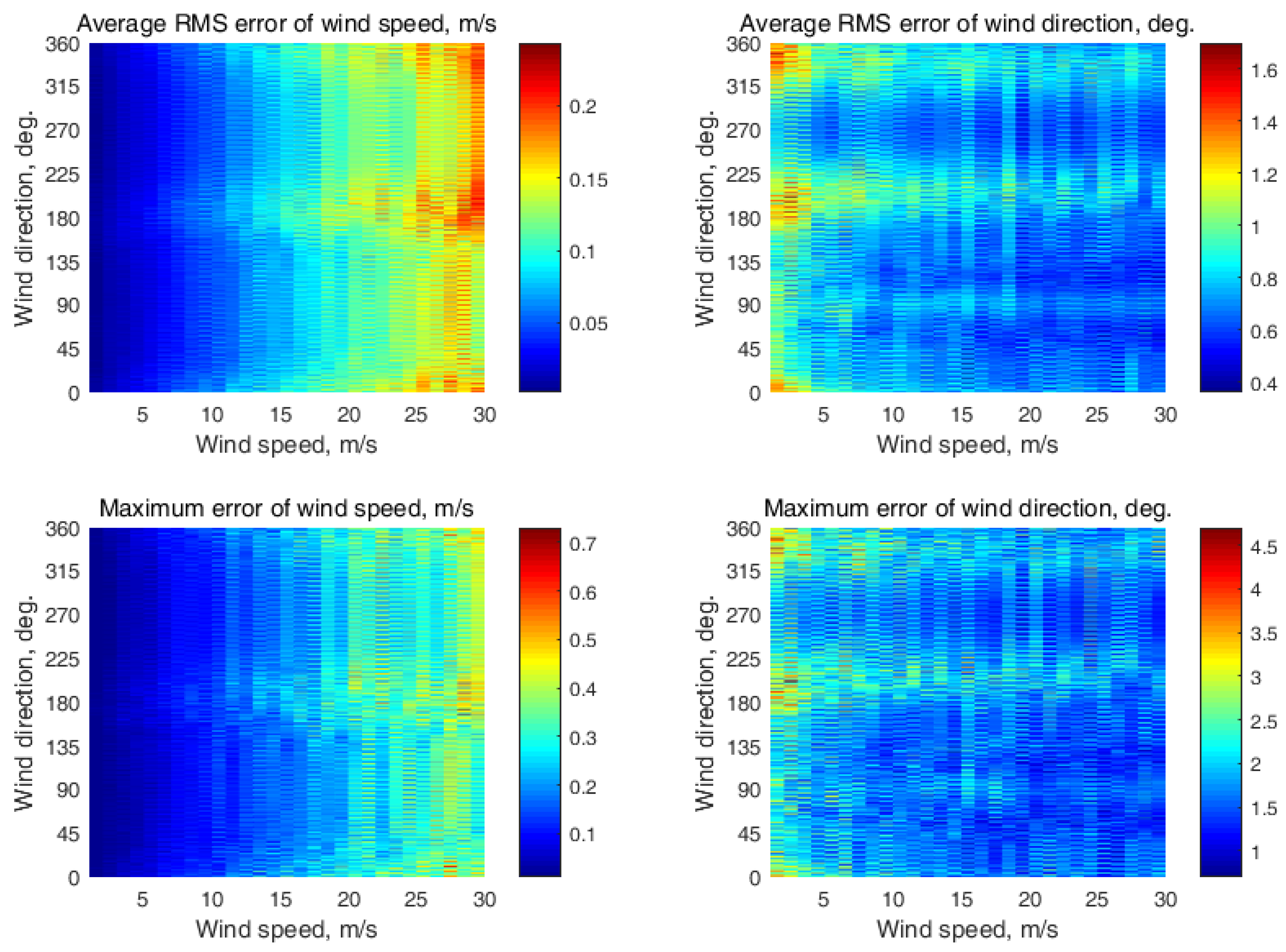
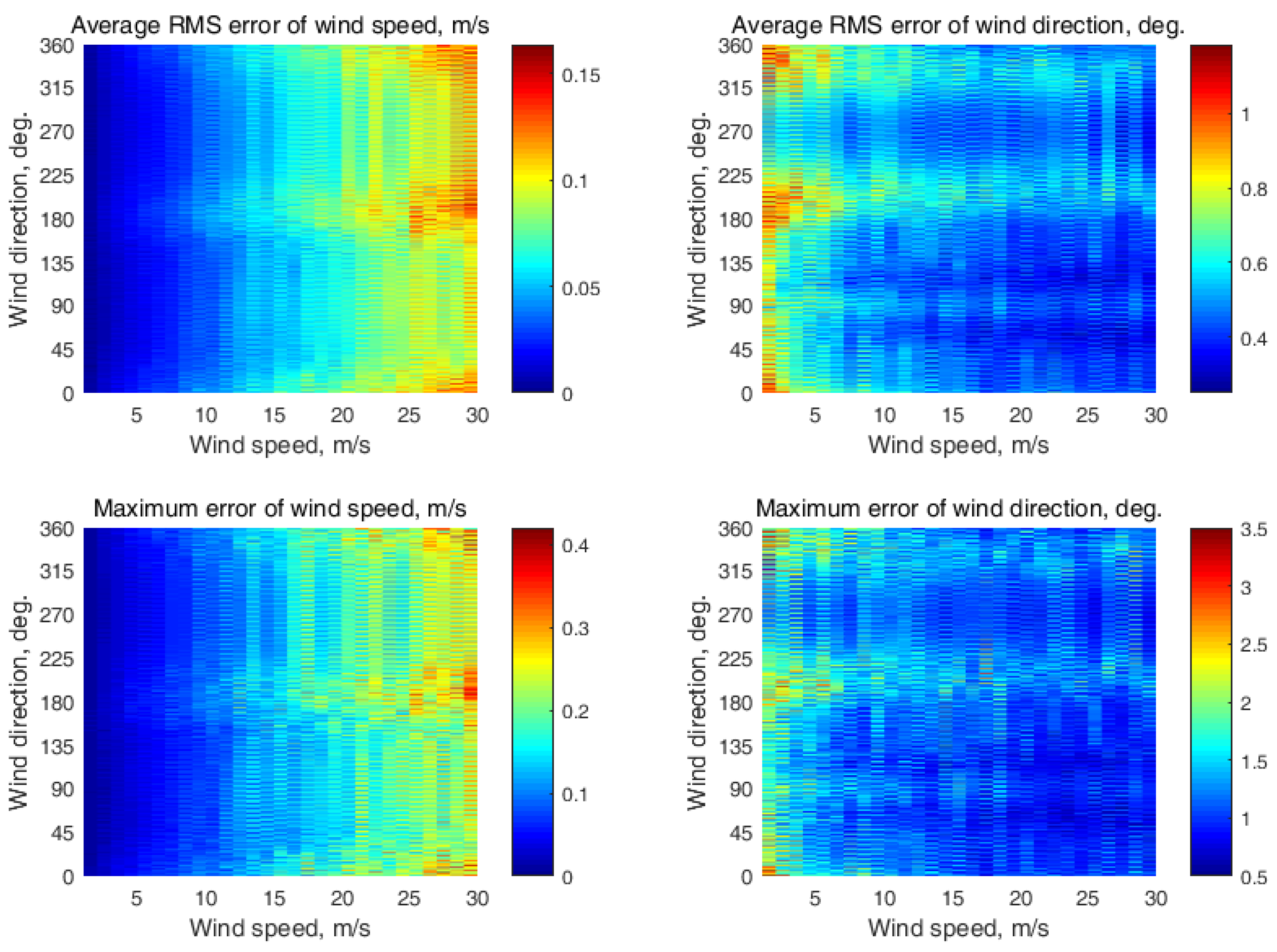
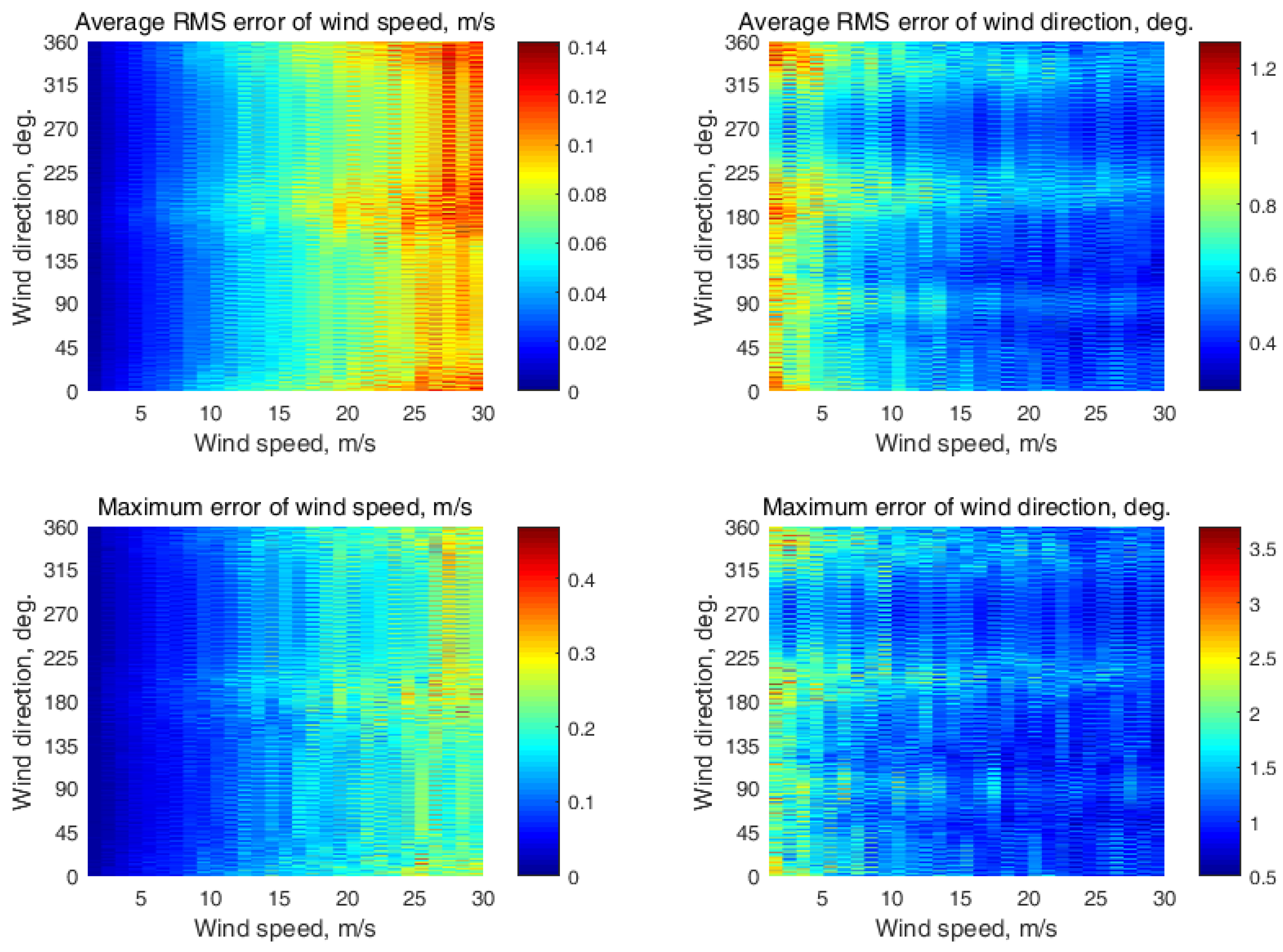
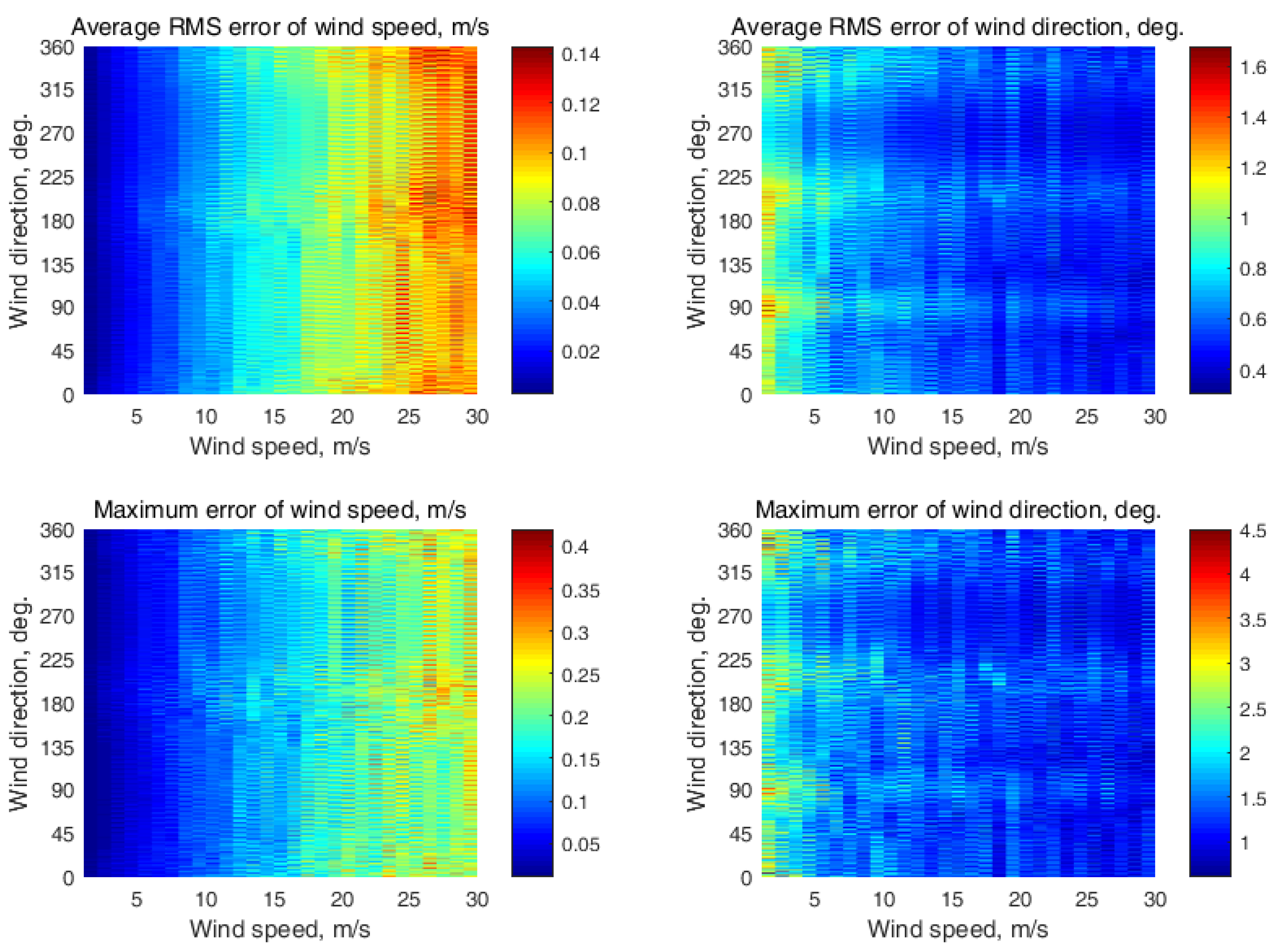
The simulation results with the semicircular NRCS sampling scheme at a single incidence angle are presented in Appendix B (Figure A2, Figure A3, Figure A4, Figure A5, Figure A6, Figure A7 and Figure A8, respectively, at incidence angles from 30° to 60° with a 5° step). The maximum errors of the wind recovery were 0.74 m/s and 5.2° at the 30° incidence angle, 0.78 m/s and 4.8° at the 35° incidence angle, 0.7 m/s and 5° at the 40° incidence angle, 0.67 m/s and 5.3° at the 45° incidence angle, 0.73 m/s and 4.7° at the 50° incidence angle, 0.7 m/s and 4.2° at the 55° incidence angle, and 0.65 m/s and 4.2° at the 60° incidence angle.
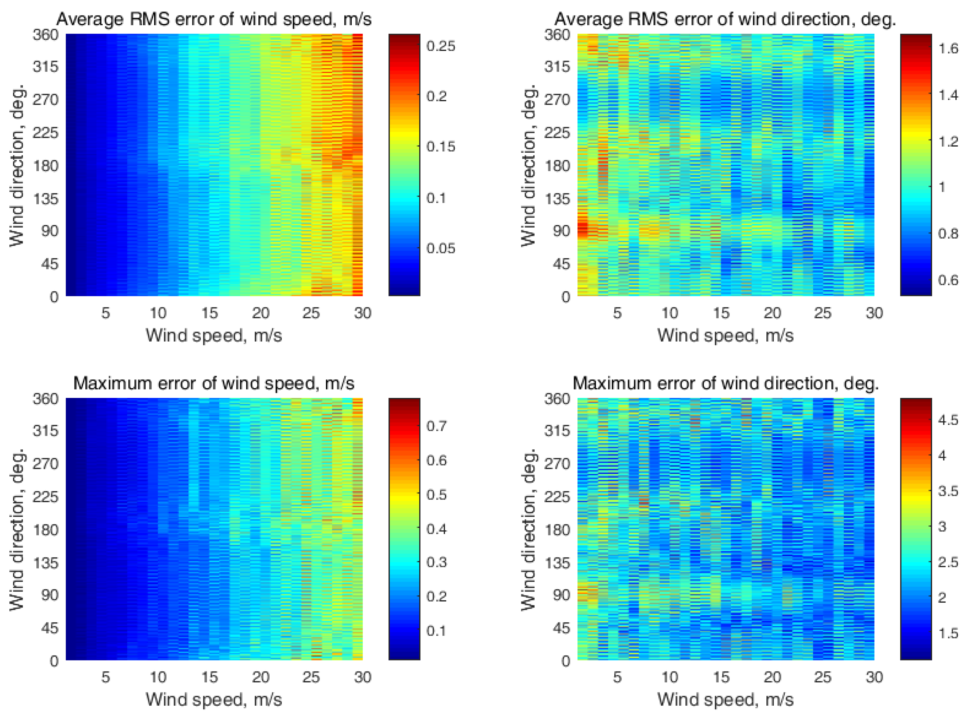
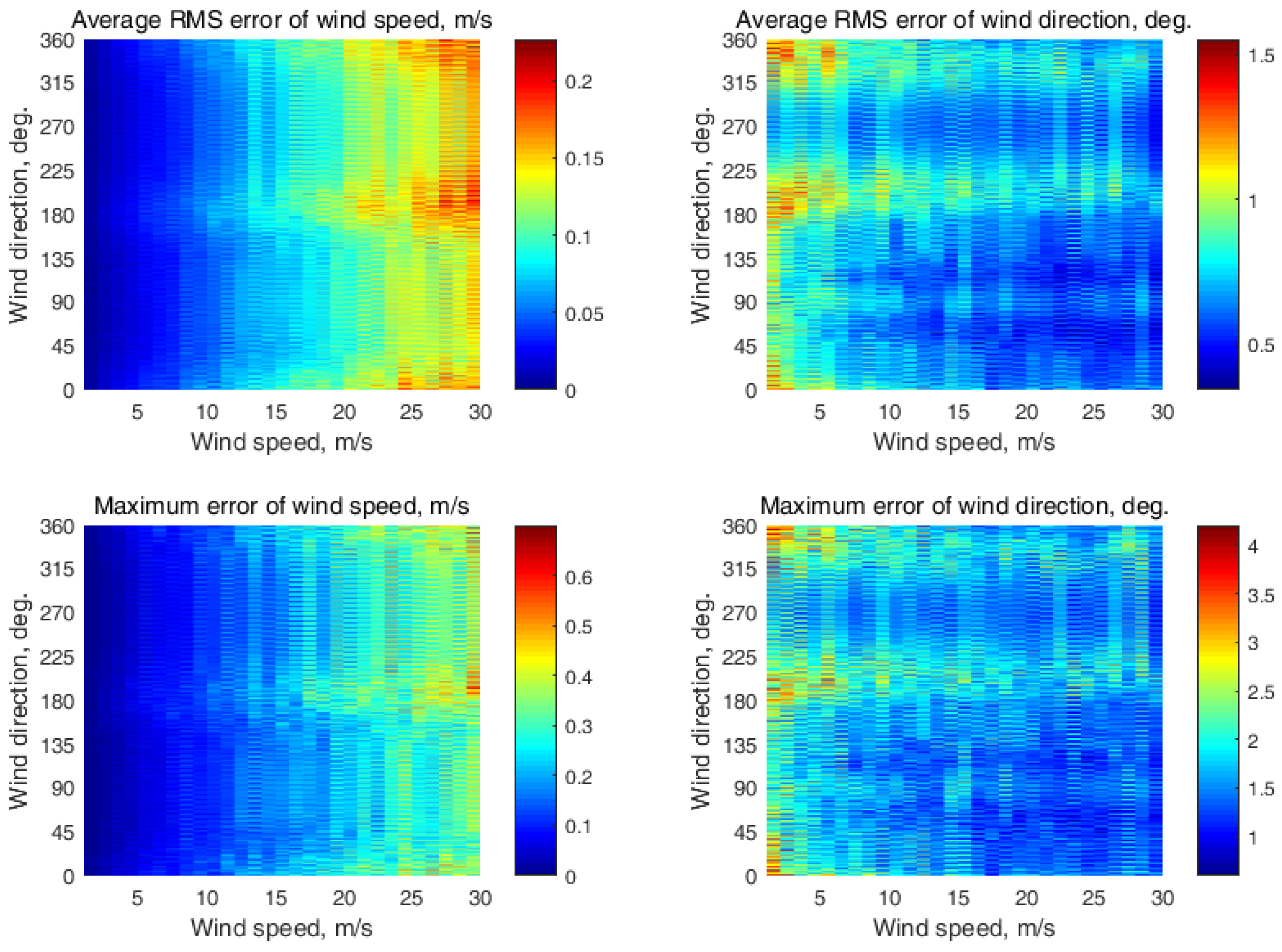
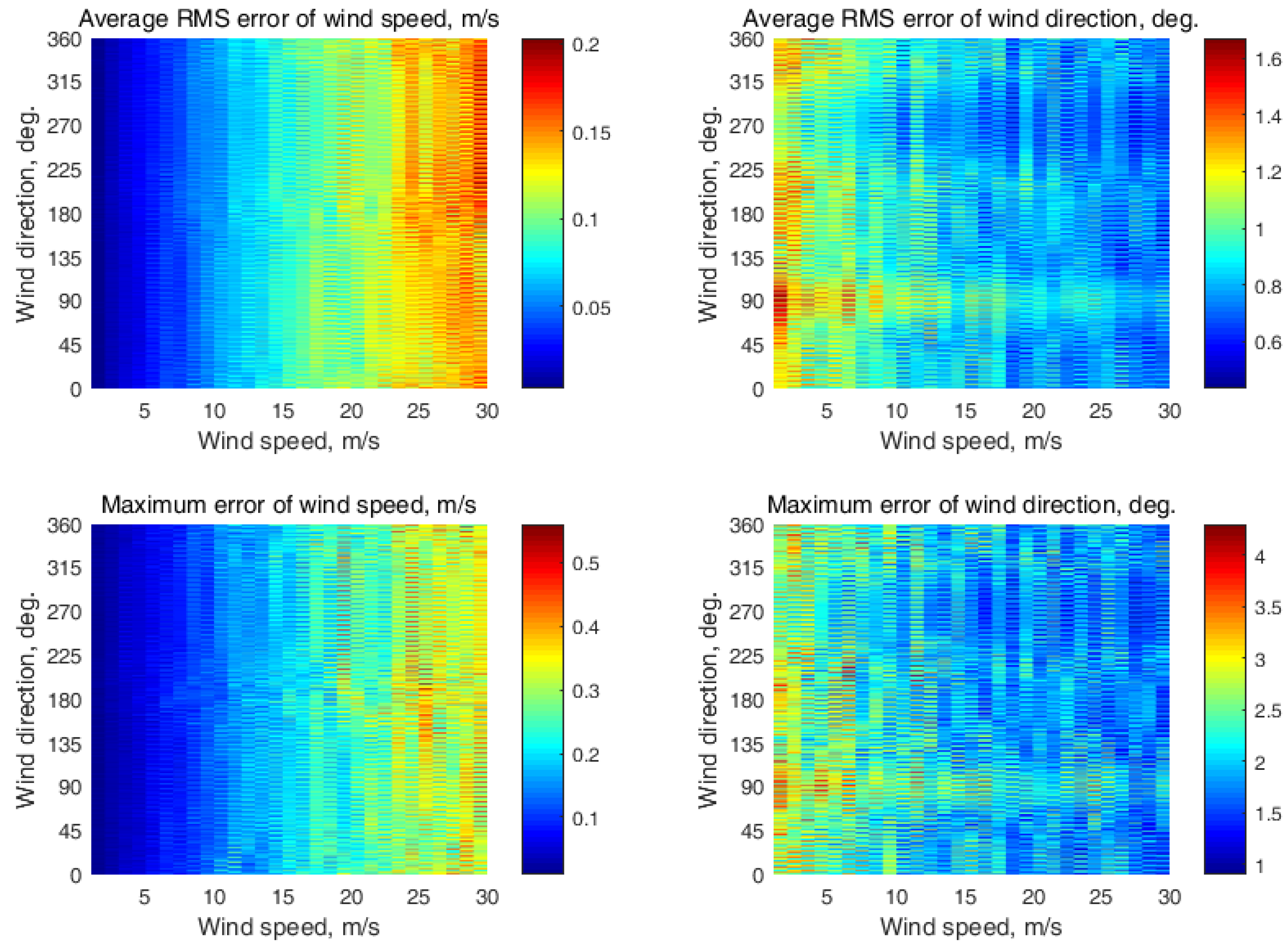
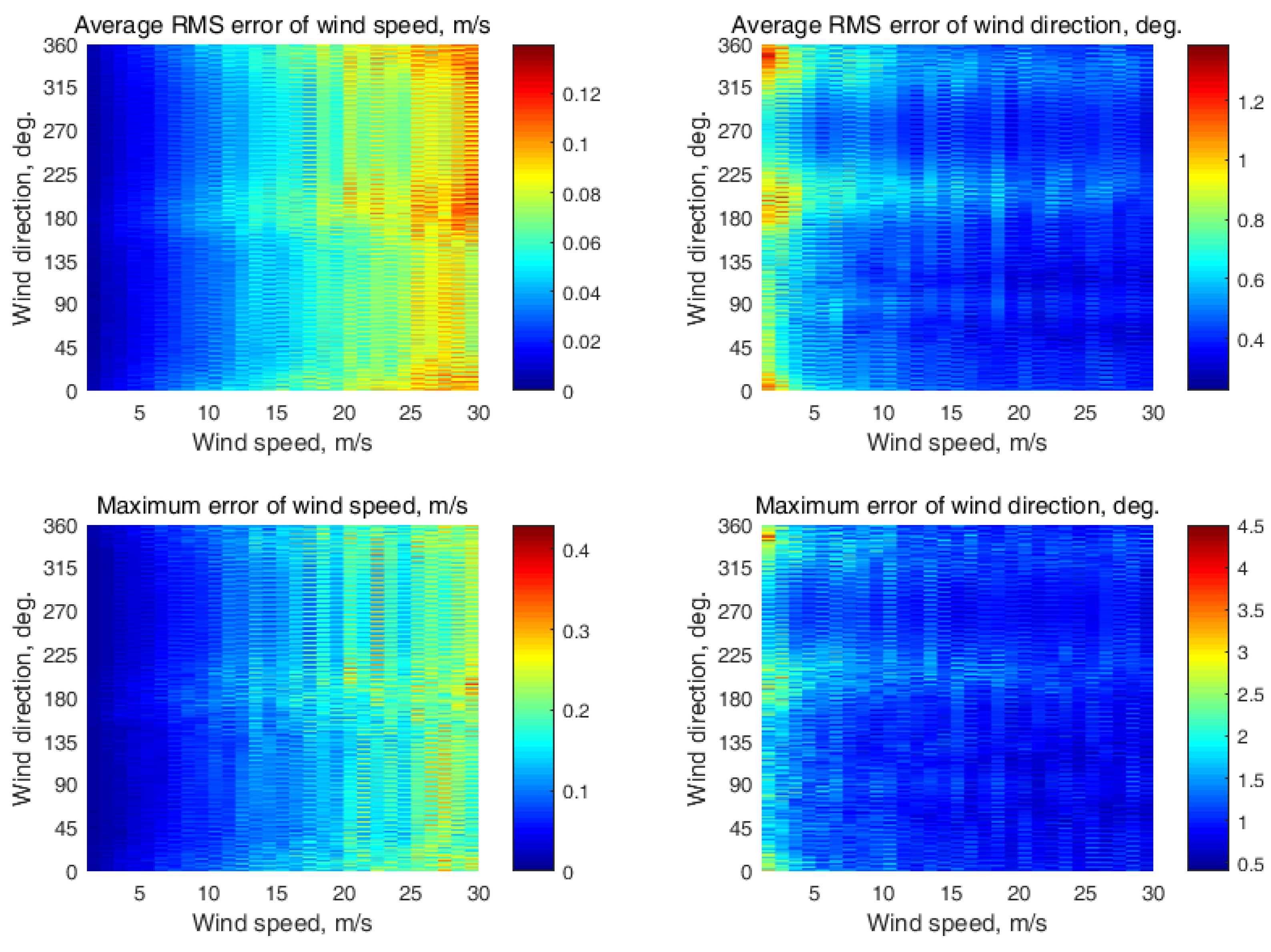
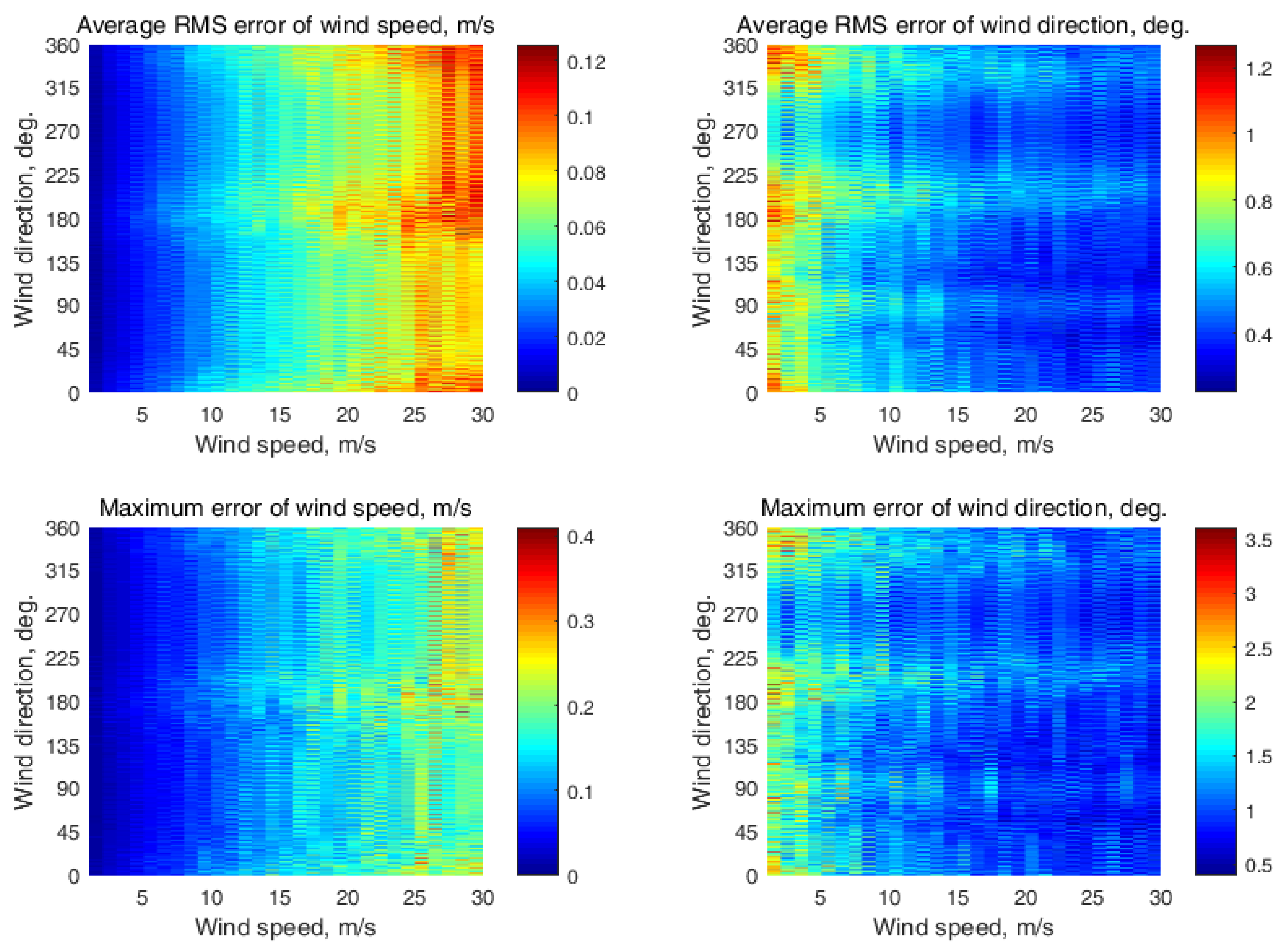
The semicircular NRCS sampling scheme simulation results at two neighboring incidence angles are shown in Appendix C (Figure A9, Figure A10, Figure A11, Figure A12, Figure A13 and Figure A14, respectively, at the following incidence angle combinations: (30°, 35°); (35°, 40°); (40°, 45°); (45°, 50°); (50°, 55°); and (55°, 60°)). The wind estimation maximum errors were 0.6 m/s and 4.4° at the (30°, 35°) incidence angle combination, 0.62 m/s and 4.6° at the (35°, 40°) incidence angle combination, 0.49 m/s and 4.6° at the (40°, 45°) incidence angle combination, 0.51 m/s and 3.9° at the (45°, 50°) incidence angle combination, 0.5 m/s and 4.6° at the (50°, 55°) incidence angle combination, and 0.42 m/s and 3.5° at the (55°, 60°) incidence angle combination.
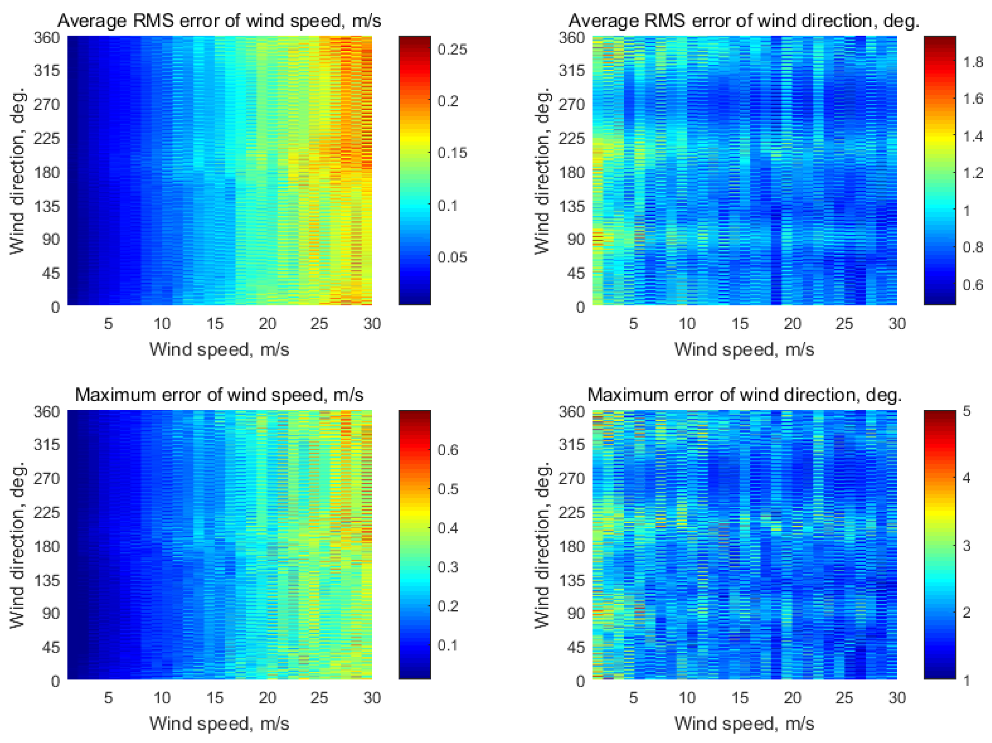
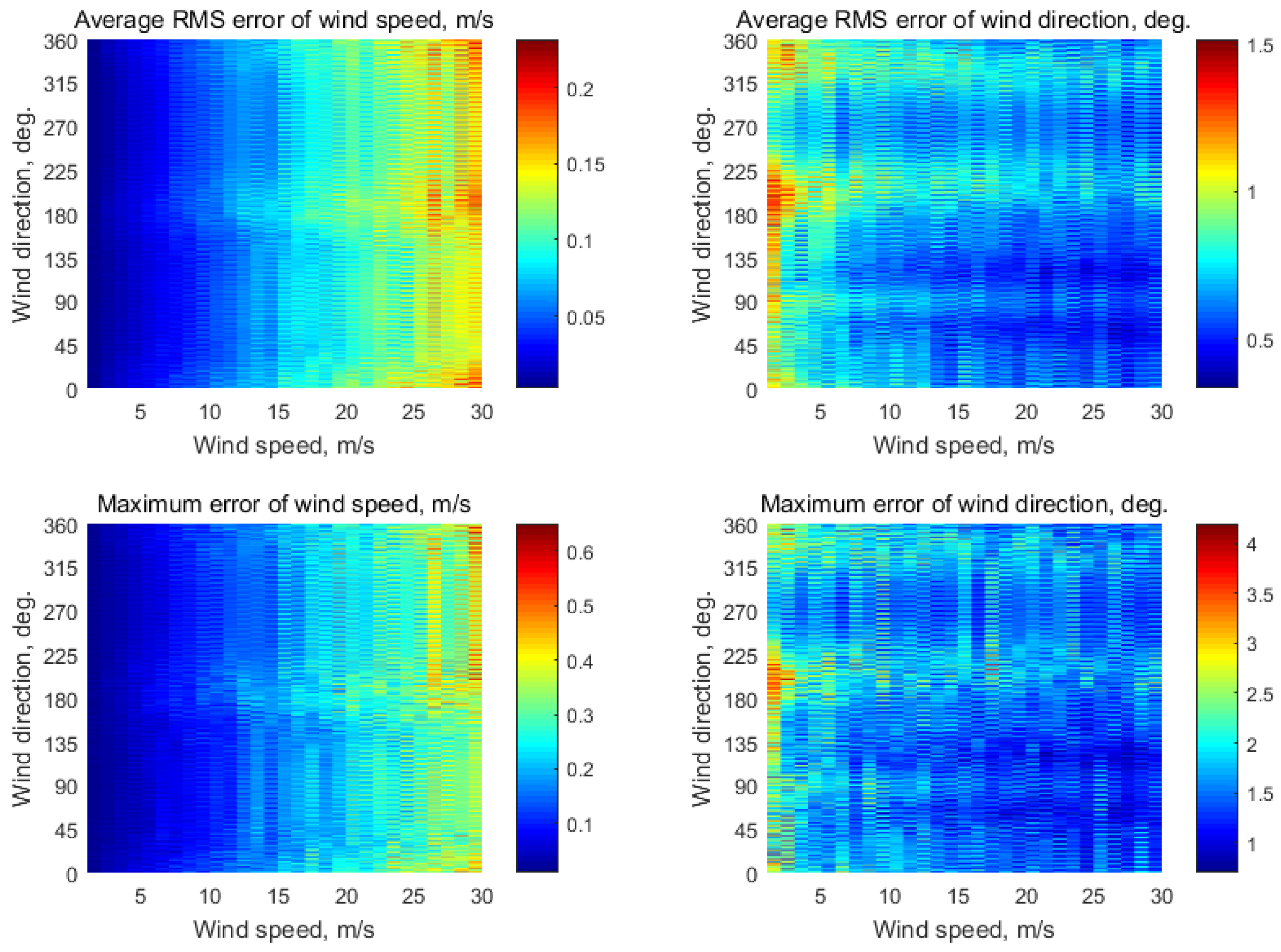
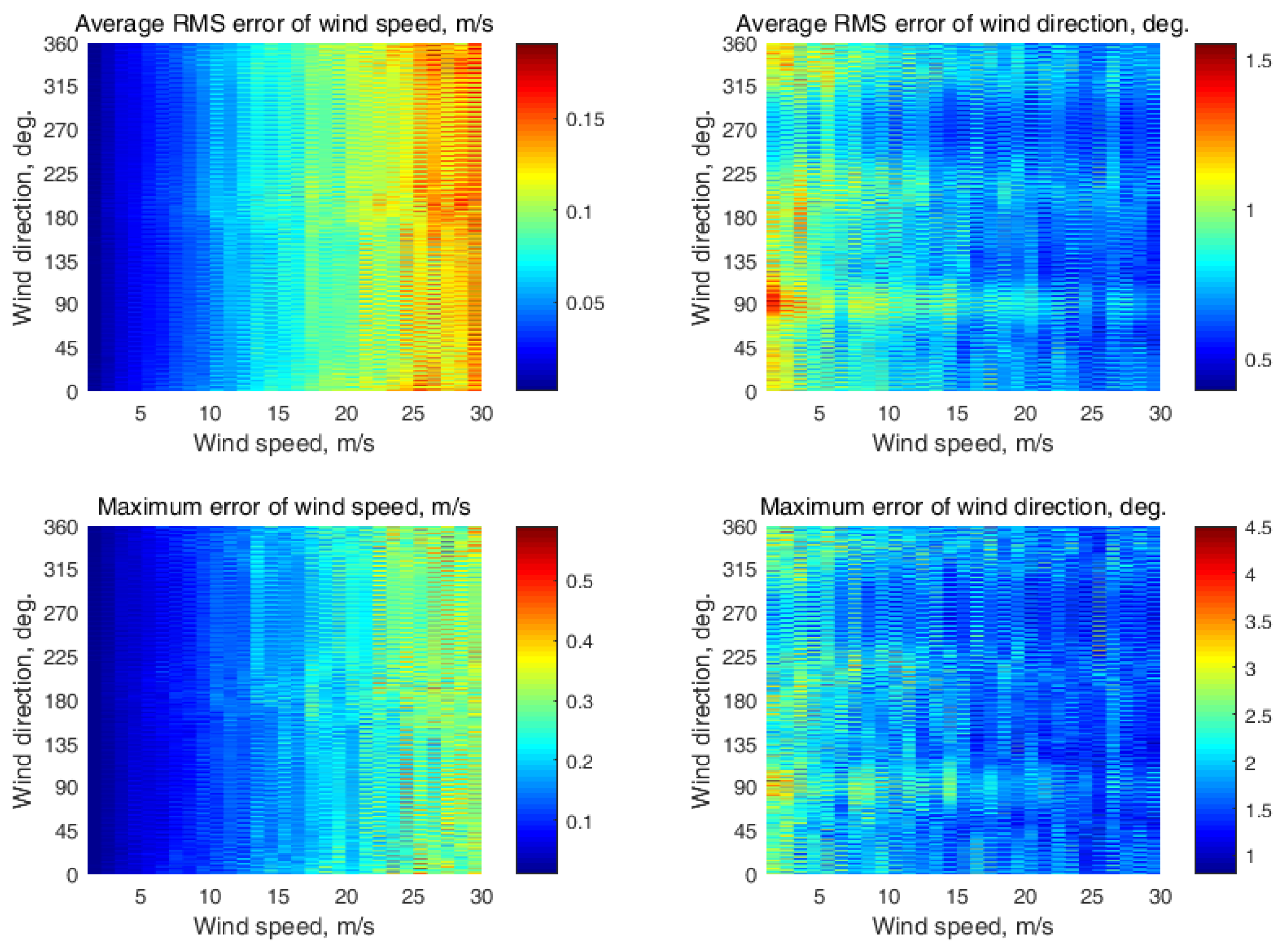
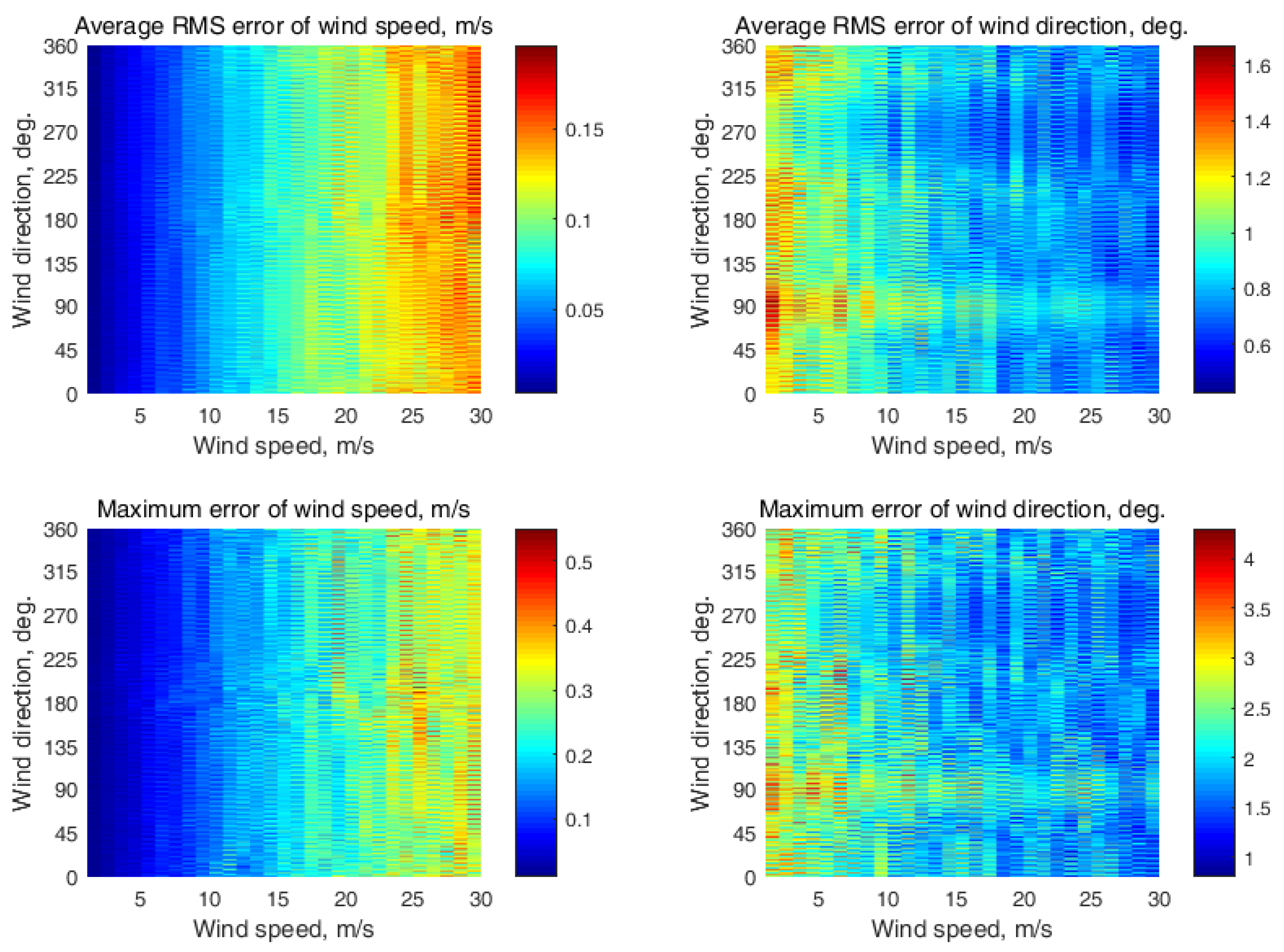
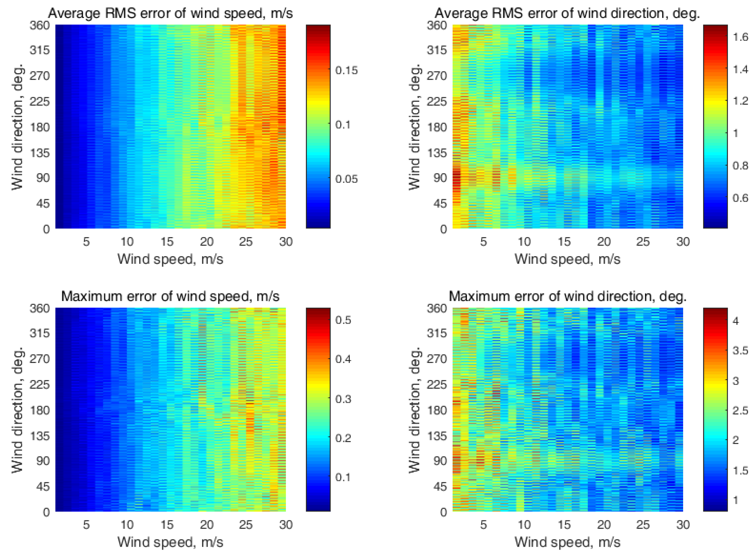
The results for the semicircular NRCS sampling scheme at three neighboring incidence angles are shown in Appendix D (Figure A15, Figure A16, Figure A17, Figure A18 and Figure A19, respectively, at the following incidence angle combinations: (30°, 35°, 40°); (35°, 40°, 45°); (40°, 45°, 50°); (45°, 50°, 55°); and (50°, 55°, 60°)). The maximum errors were 0.56 m/s and 4.3° at the (30°, 35°, 40°) incidence angle combination, 0.59 m/s and 4.5° at the (35°, 40°, 45°) incidence angle combination, 0.44 m/s and 4.5° at the (40°, 45°, 50°) incidence angle combination, 0.47 m/s and 3.7° at the (45°, 50°, 55°) incidence angle combination, and 0.43 m/s and 4.5° at the (50°, 55°, 60°) incidence angle combination.
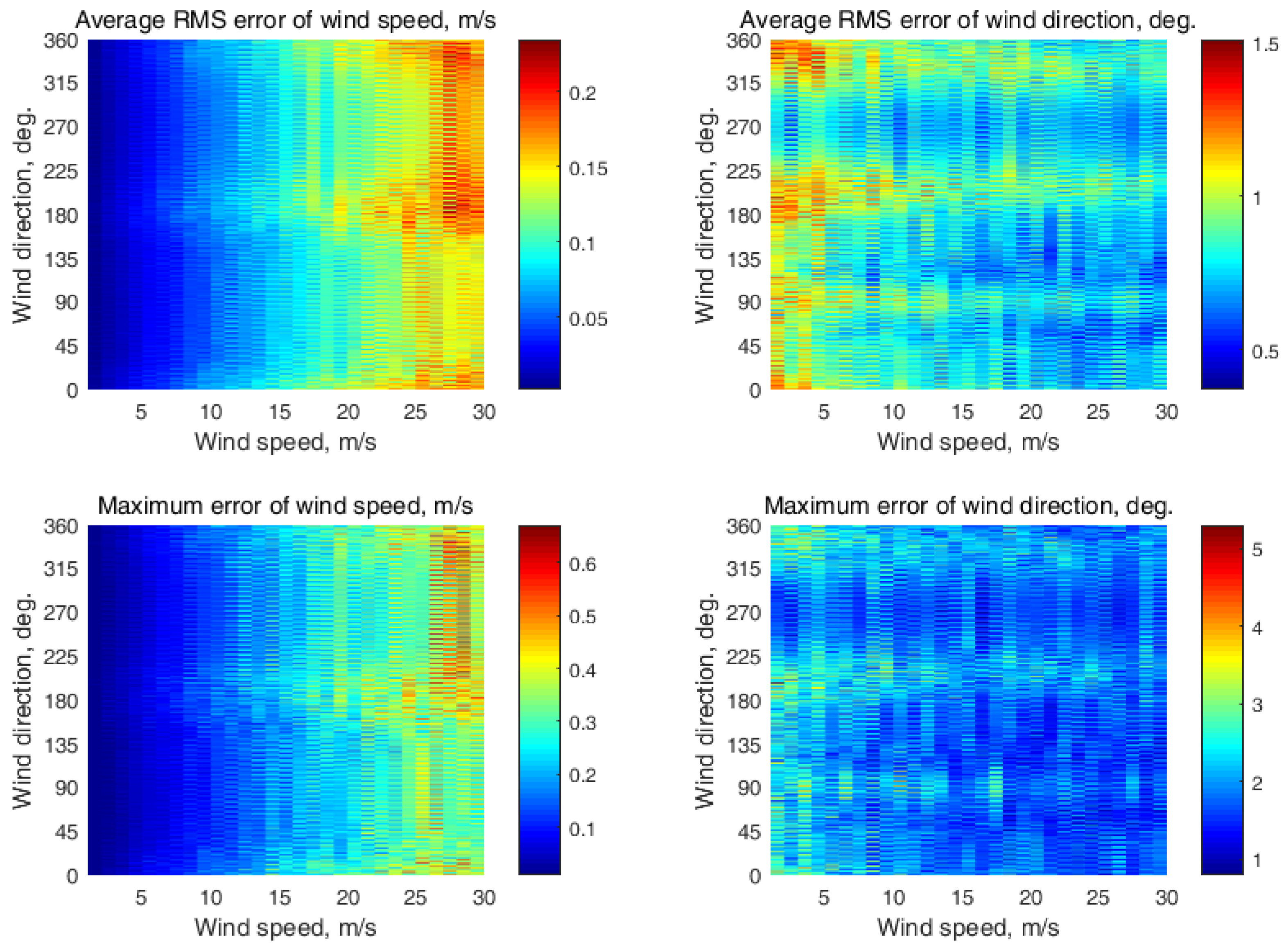
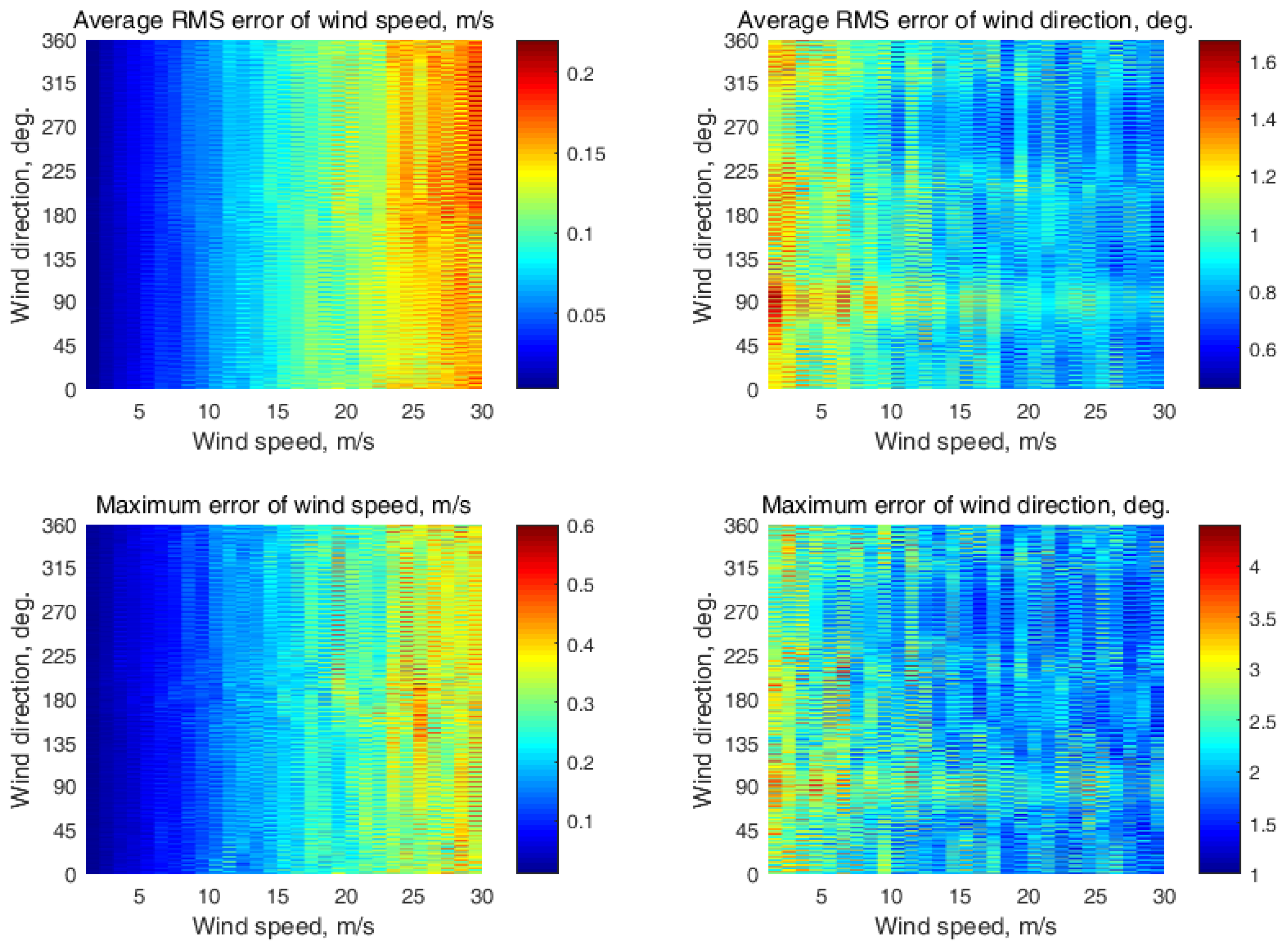
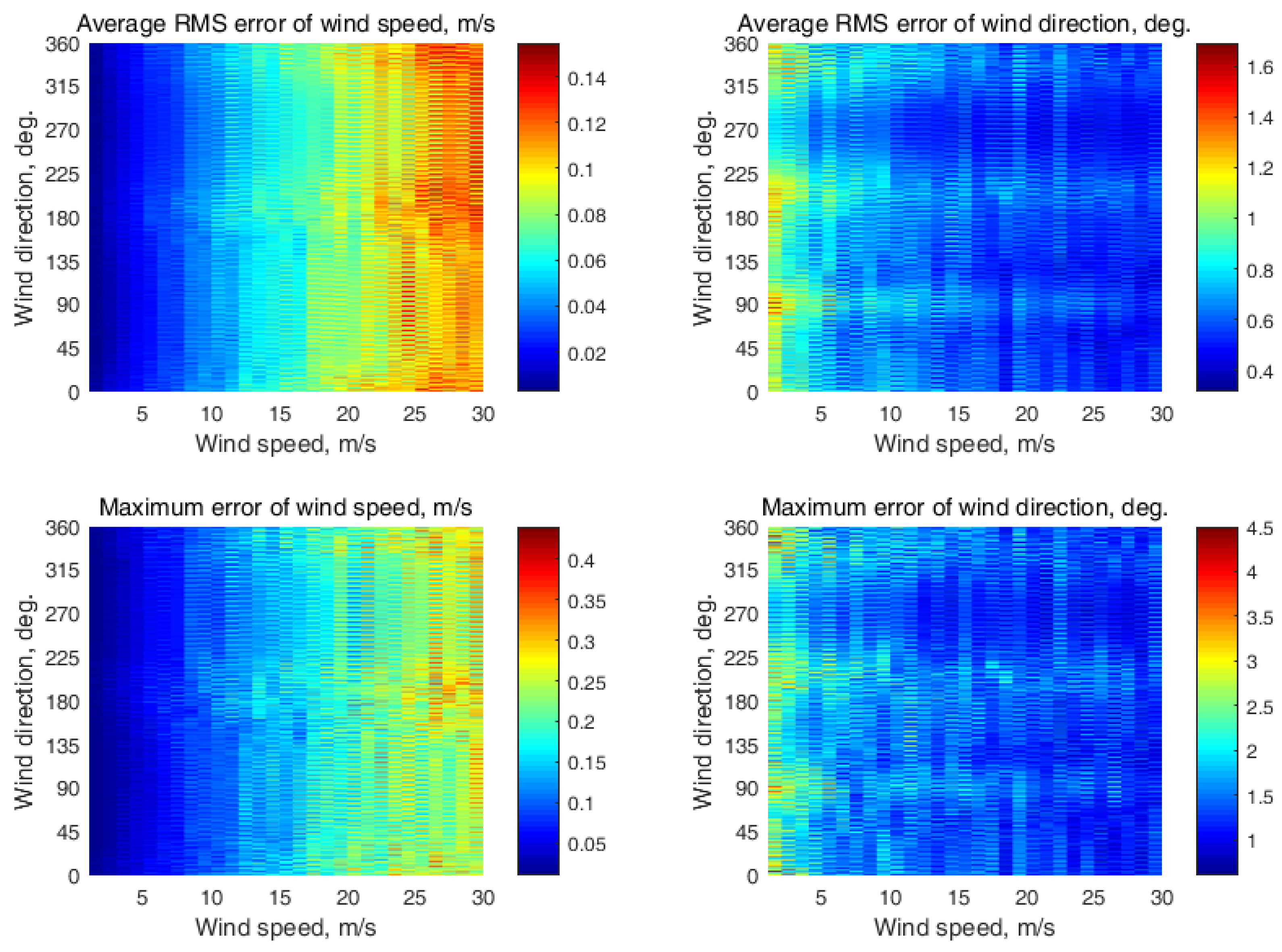
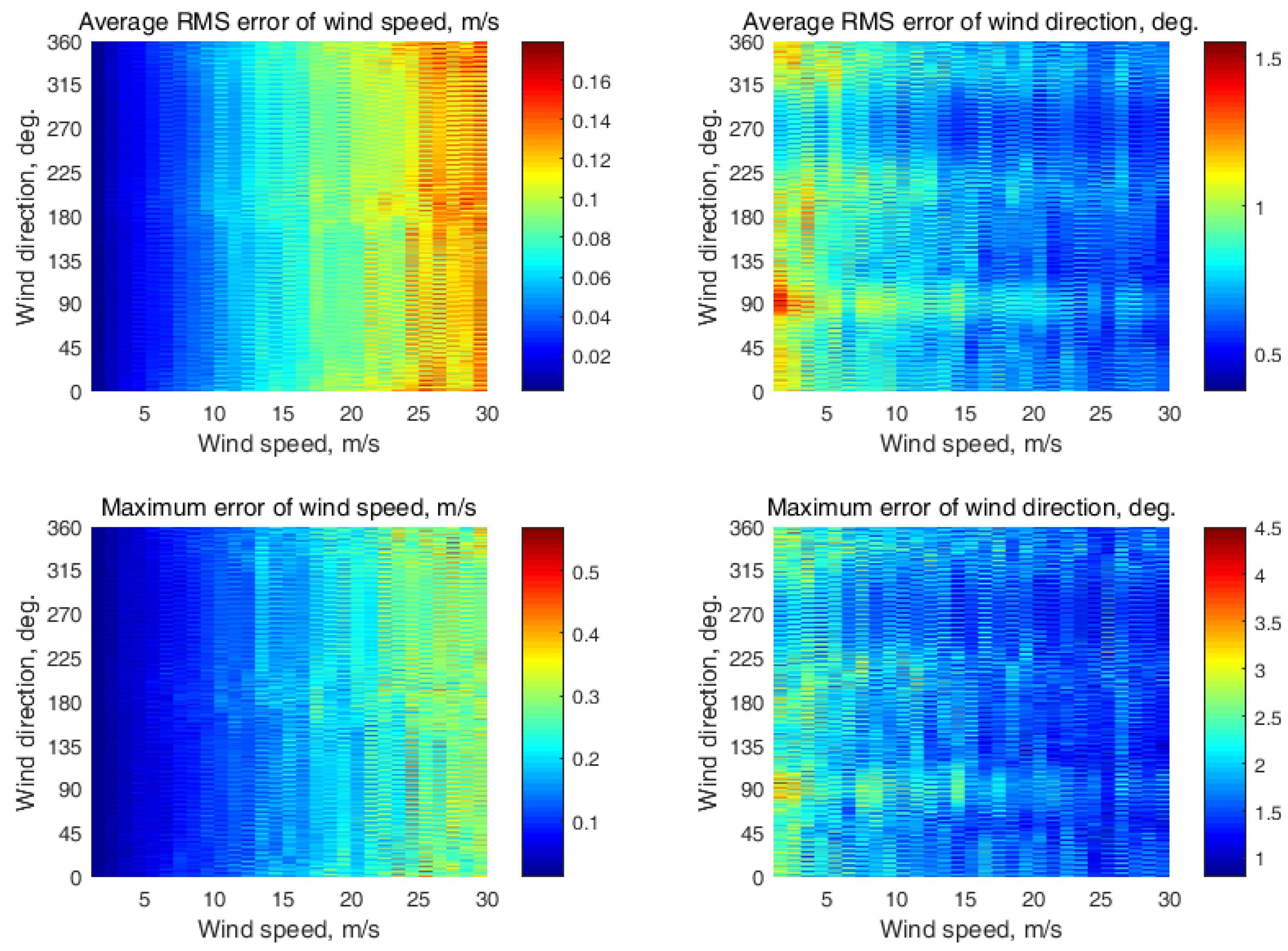
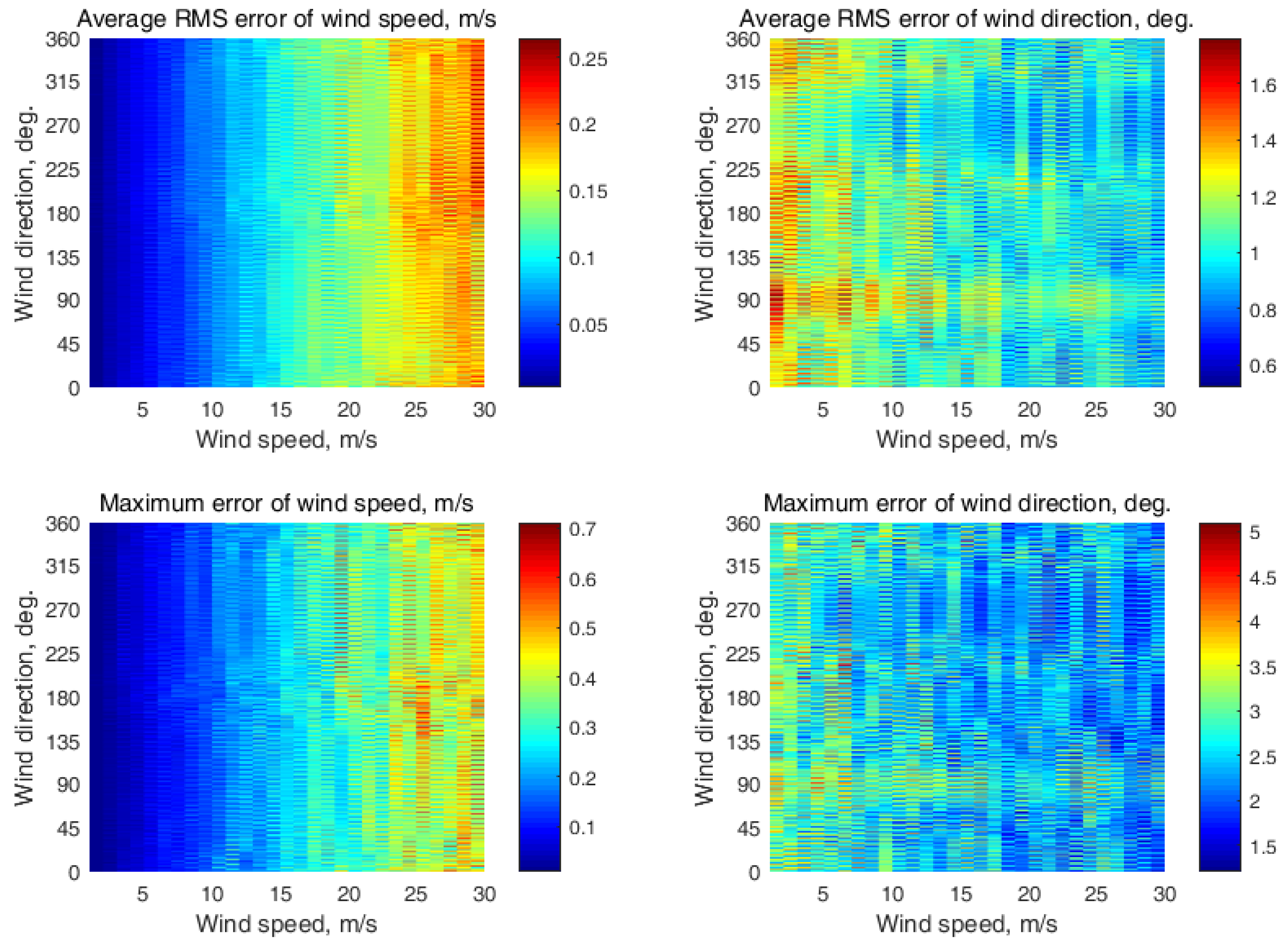
The results for the semicircular NRCS sampling scheme simulation at four neighboring incidence angles are depicted in Appendix E (Figure A20, Figure A21, Figure A22 and Figure A23, respectively, at the following incidence angle combinations: (30°, 35°, 40°, 45°); (35°, 40°, 45°, 50°); (40°, 45°, 50°, 55°); and (45°, 50°, 55°, 60°)). The wind recovery maximum errors were 0.55 m/s and 4.3° at the (30°, 35°, 40°, 45°) incidence angle combination, 0.57 m/s and 4.5° at the (35°, 40°, 45°, 50°) incidence angle combination, 0.42 m/s and 4.5° at the (40°, 45°, 50°, 55°) incidence angle combination, and 0.41 m/s and 3.6° at the (45°, 50°, 55°, 60°) incidence angle combination.
The results for the semicircular NRCS sampling scheme at seven neighboring incidence angles for wind estimation are shown in Appendix F (Figure A24, at the following incidence angle combination: (30°, 35°, 40°, 45°, 50°, 55°, 60°)). The maximum errors were 0.53 m/s and 4.2° at this incidence angle combination.
In addition, the wind retrieval maximum errors were evaluated for the semicircular NRCS sampling scheme in the particular case of three incidence angles when the highest difference in the incidence angle between the neighboring incidence angles in the given incidence angle ranged from 30° to 60°, which was 15°, took place. The results of the simulation are shown in Appendix G (Figure A25, for the following combination of incidence angles: (30°, 45°, and 60°)). The maximum errors in this particular case were 0.71 m/s and 5.1°.
The simulation results presented in Appendix B, Appendix C, Appendix D, Appendix E, Appendix F and Appendix G also display the horizontal strips with the higher and lower wind retrieval errors. Their presence was due to the semicircular NRCS sampling scheme, because in this specific sampling scheme only a half of the full azimuth (circular) NRCS curve is obtained, so three of four extremes of the full azimuth NRCS curve (corresponding to the GMF main maximum, second maximum, and two minima) do not always fall into an observed semicircular sector. This leads to an increase in the wind retrieval errors under certain azimuth angles, which can be seen as the horizontal strips in Appendix B, Appendix C, Appendix D, Appendix E, Appendix F and Appendix G. Therefore, we had to take this effect into account, mainly by analyzing the maximum errors.
The simulation results obtained with the semicircular NRCS sampling scheme, shown in Figure 4, clearly show that NRCS sampling simultaneously from several neighboring incidence angles increases the wind speed and direction retrieval accuracy in comparison with the single incidence angle case.
From Figure 4, we can see that wind recovery simultaneously using all the given incidence angles (i.e., 30°, 35°, 40°, 45°, 50°, 55°, and 60°) produced better wind speed retrieval accuracy than with a single incidence angle. Its improvement was 0.18 m/s on average in the range of the considered incidence angles. Such an improvement is significant for the wind scatterometer. However, we can also see that the combination of seven incidence angles had little impact on the accuracy of the wind direction retrieval, as the improvement was on average 0.6° only. Thus, we can conclude that the simultaneous use of these seven incidence angles for wind retrieval is not the best way to improve the overall wind retrieval accuracies with the semicircular NRCS sampling scheme.
In addition, from Figure 4 we can see that the two, three, and four incidence angle combinations provided increased wind measurement accuracies, especially for the wind speed retrieval, with an increasing number of simultaneously used incidence angles in the semicircular NRCS sampling scheme. Predominantly, the simultaneous use of three and four incidence angles provided the lowest values of the maximum errors for wind speed and direction recovery in the incidence angles’ range of interest, with four incidence angles generally performing best of all. Compared to the single incidence angle case, the accuracy improvement in the case of three incidence angles was 0.21 m/s on average for wind speed retrieval and 0.5° on average for recovery of the wind direction. At the same time, the accuracy improvement in the case of four incidence angles on average was 0.22 m/s for wind speed retrieval and 0.7° for wind direction recovery.
However, the combination of two incidence angles produced slightly higher wind recovery errors compared with the combinations of three and four incidence angles but significantly fewer wind retrieval errors than occurred for a single incidence angle. The accuracy improvement was 0.17 m/s on average for the wind speed retrieval and 0.3° on average for the wind direction recovery in the case of two incidence angles compared to the single incidence angle case. Therefore, the combination of two incidence angles can be considered a simpler alternative to the simultaneous use of three or four incidence angles for the improvement of wind retrieval accuracies.
Regrettably, the black, dashed line in Figure 4 also shows that the semicircular NRCS sampling scheme at three incidence angles, possessing the highest 15° difference in the incidence angle between the neighboring incidence angles in the given incidence angles’ range from 30° to 60° (i.e., 30°, 45°, 60°) actually did not improve the wind retrieval accuracies even in comparison with the worst single incidence angle case.
Despite some shortcomings in improving the accuracy of the wind measurements at some combinations of the incidence angles, all of the simulated cases demonstrated that the wind retrieval accuracies were better than their typical values of ±2 m/s and ±20° for scatterometers [41].
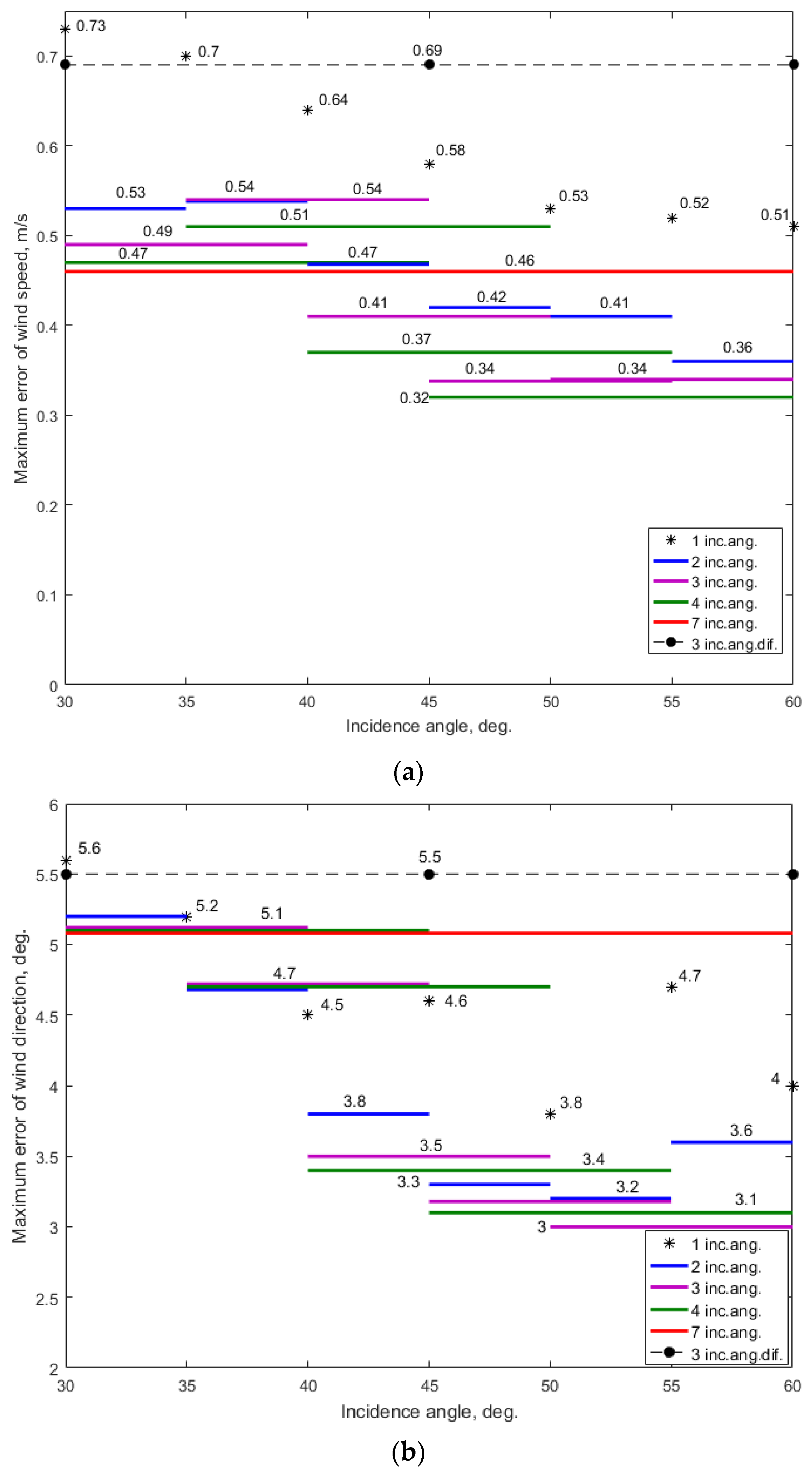
This outcome, of course, was expected by analogy to our previously obtained results with circular NRCS sampling schemes using multiple incidence angles [17]. For a direct comparison with our new semicircular results, the previous circular NRCS sampling scheme’s results [17] are reproduced here in Figure 5.
Comparing the simulation results for the semicircular NRCS sampling scheme (Figure 4) with the wind retrieval results with a circular NRCS sampling scheme (Figure 5), we can see that the semicircular scheme provides wind retrieval accuracies similar to those achievable with the circular scheme when increased approximately three times the number of the NRCS samples integrated in each azimuth sector compared to the circular scheme used. There is a tendency for the wind retrieval accuracy to increase when increasing the incidence angle in the semicircular scheme, but this is not as strongly pronounced as in the circular case. Thus, these results also prove the feasibility of the semicircular scheme for wind measurements over the sea in the considered 30°–60° incidence angle range.
In spite of the need for a higher number of integrated NRCS samples, approximately three times higher, the semicircular NRCS sampling scheme has an undeniable advantage in enabling twice the maximum altitude for wind recovery compared to the circular scheme of NRCS sampling [30]. This is especially important for wind measurements over the sea’s surface by airborne high-altitude conical scanning radars with a scatterometer mode, e.g., HIWRAP.
While keeping similar wind retrieval accuracies, the semicircular NRCS sampling scheme provides maximum altitudes for wind measurement for the combinations of 1, 2, 3, and 4 neighboring incidence angles, beginning with the incidence angle of 30°, as 34.6, 28.4, 23.8, and 20 km, respectively. These values were obtained taking into account that the wave and wind conditions are identical in all the parts of the area observed, with typical sizes of approximately 15–20 km. By comparison, the circular NRCS sampling scheme enables wind measurement maximum altitudes of only 17.3, 14.2, 11.9, and 10 km, respectively.
Therefore, with regard to high-altitude conical scanning radar, this allows not only for increasing the maximum altitude for wind retrieval but also improves the accuracy of wind measurements by the several incidence angles used simultaneously in the semicircular NRCS sampling scheme. The simplest combination that allows for approximately the highest altitude and increased wind retrieval accuracies is the use of the (30°, 35°) incidence angle combination (similar to that shown in Figure 1), allowing for a maximum altitude for wind retrieval of approximately 28.4 km.
At the other extreme, the lowest maximum altitudes for wind measurement are for a combination of seven neighboring incidence angles and for a three incidence angle combination having the highest 15° incidence angle difference between the neighboring incidence angles in the given 30°–60° incidence angle range. This lowest wind measurement maximum altitude is 11.54 km at the semicircular NRCS sampling scheme and 5.77 km at the circular NRCS sampling scheme.
Thus, we have again confirmed that the semicircular NRCS sampling scheme can also be used for wind measurements over the sea as effectively as a conventional circular scheme, given the appropriate choices for the numbers and angles of the antenna beams. Wind retrieval using a semicircular scheme allows for doubling the wind measurement maximum altitude compared to the circular scheme and can provide wind retrieval accuracies similar to those of the circular NRCS sampling scheme, although it requires approximately three times the number of NRCS samples integrated in each observed azimuth sector. The largest incidence angle in the incidence angle combination determines the maximum altitude of the wind retrieval method applicable in accordance with the azimuth NRCS sampling scheme. As the semicircular NRCS sampling scheme requires approximately a three times higher number of integrated NRCS samples compared to the typical semicircular NRCS sampling scheme, it may also need several antenna turns to gather the required (i.e., increased) number of NRCS samples, which could lead to increasing the time of the wind retrieval.
As with other wind scatterometers, in the considered azimuth NRCS sampling schemes, to provide a more accurate measurement of the wind direction, it is desirable to use a GMF of the band that provides the largest difference between the two maxima and the largest difference between the maxima and minima. For example, from that point of view, the considered Ku-band GMF is better than the X-band GMF and even more preferred than the C-band GMF. Moreover, the horizontal transmit and receive polarization is preferable to the vertical transmit and receive polarization, as it provides greater upwind/downwind differences in the NRCS values of a GMF, and so it allows for better retrieval of the wind direction.
4. Conclusions
We studied the applicability of a semicircular NRCS sampling scheme when both single and multiple incidence angles are applied for wind recovery over the sea’s surface by airborne scatterometers or multimode radars operated in scatterometer mode and having a rotating-beam antenna. The importance of this study lies in improving the wind measurement accuracy of airborne scatterometers, as well as in increasing the maximum altitude of the wind retrieval method’s applicability. Such an outcome opens up the possibility of the approach’s use on high-altitude aircraft or UAVs.
This study extends our previous results and further proves the feasibility of the semicircular NRCS sampling scheme, allowing wind retrieval accuracies similar to those achievable with a circular NRCS sampling scheme, although it requires increasing by a factor of three the number of NRCS samples integrated in each azimuth sector compared to the circular NRCS sampling scheme. Nevertheless, our semicircular NRCS sampling scheme allows for maximum altitudes for wind retrieval twice as high as those possible with a circular scheme.
Our simulations have demonstrated that the accuracy of wind speed measurements tends to increase with the increase in the incidence angle in the considered 30°–60° incidence angle range. A similar trend is also shown for wind direction retrieval. It is also important that all various combinations of incidence angles in the simulated cases considered demonstrated that the wind retrieval accuracies are better than the typical ±2 m/s and ±20° scatterometer accuracy [41].
The new NRCS semicircular sampling results in this paper showed that the simultaneous application of several incidence angles increases wind retrieval accuracy, especially when three or four incidence angles are used. However, an increase in the incidence angle number leads to a maximum altitude decrease in the wind recovery method, as the largest incidence angle in the incidence angle combination determines the maximum altitude of the wind retrieval method’s applicability accordingly with the azimuth NRCS sampling scheme. The highest maximum altitudes of the method for wind estimation over the sea are achieved with a single incidence angle.
In the semicircular NRCS sampling scheme, the wind estimation method’s maximum altitudes allowed for the considered combinations of one, two, three, and four neighboring incidence angles, beginning with an incidence angle of 30°, are 34.6, 28.4, 23.8, and 20 km, respectively. By contrast, a circular NRCS sampling scheme supports only half the maximum altitudes at 17.3, 14.2, 11.9, and 10 km [17].
The maximum altitude, the lowest for wind measurements, is 11.54 km in the semicircular NRCS sampling scheme, and 5.77 km in the circular scheme. These correspond to the seven neighboring incidence angle combination, with the combination of three incidence angles having the highest 15° incidence angle difference between the neighboring incidence angles in the given 30°–60° incidence angle range.
With regard to high-altitude conical scanning radar, our semicircular NRCS sampling scheme allows not only for increasing the maximum altitude for wind recovery but also improves the accuracy of wind measurements by the several incidence angles simultaneously used. The simplest solution in this way allowing for almost the highest altitude and increased wind retrieval accuracies was the simultaneous use of two neighboring incidence angles. The best combination encountered in our experiments in this case was the simultaneous use of two neighboring incidence angles. Namely, the (30°, 35°) incidence angle combination provides a maximum altitude for wind retrieval of approximately 28.4 km, which is not much lower than the highest maximum altitude of 34.6 km of the wind estimation method achievable at observations with a single 30° incidence angle.
The obtained results are important for optimizing the NRCS sampling procedure for wind measurements over the sea with airborne rotating-beam scatterometers or multimode radars with a scatterometer mode, including airborne high-altitude conical scanning radars, as well as for new remote sensing systems’ development, extending their applicability for joint and standalone measurements in the interest of operational oceanography, meteorology, and navigation.
Author Contributions
Conceptualization, A.N.; methodology, A.N., A.K. and C.F.; software, A.K.; validation, A.N., A.K. and C.F.; formal analysis, A.N. and A.K.; investigation, A.N., A.K. and C.F.; resources, A.K.; data curation, A.N. and A.K.; writing—original draft preparation, A.N.; writing—review and editing, A.N., A.K. and C.F.; visualization, A.N. and A.K.; supervision, A.N.; project administration, A.K.; funding acquisition, A.K. All authors have read and agreed to the published version of the manuscript.
Funding
This research was funded by the Russian Science Foundation, grant number: 21-79-10375, https://rscf.ru/en/project/21-79-10375 (accessed on 13 February 2023). The APC was funded by the Russian Science Foundation, grant number 21-79-10375.
Data Availability Statement
Data sharing not applicable.
Conflicts of Interest
The authors declare no conflict of interest.
Appendix A
These are the examples of the Ku-band GMF azimuthal curves using Equation (1) with coefficients for the horizontal transmit and receive polarization from Equation set (2). The NRCS azimuthal curves for the wind speeds of 2, 5, 10, 15, 20, 25, and 30 m/s at the incidence angles of 30°, 45°, and 60° are shown in Figure A1a–c, respectively.
Figure A1.
Ku-band GMF azimuthal curves for the horizontal transmit and receive polarization for wind speeds of 2, 5, 10, 15, 20, 25, and 30 m/s at an incidence angle of (a) 30°; (b) 45°; (c) 60°.
Figure A1.
Ku-band GMF azimuthal curves for the horizontal transmit and receive polarization for wind speeds of 2, 5, 10, 15, 20, 25, and 30 m/s at an incidence angle of (a) 30°; (b) 45°; (c) 60°.
Appendix B
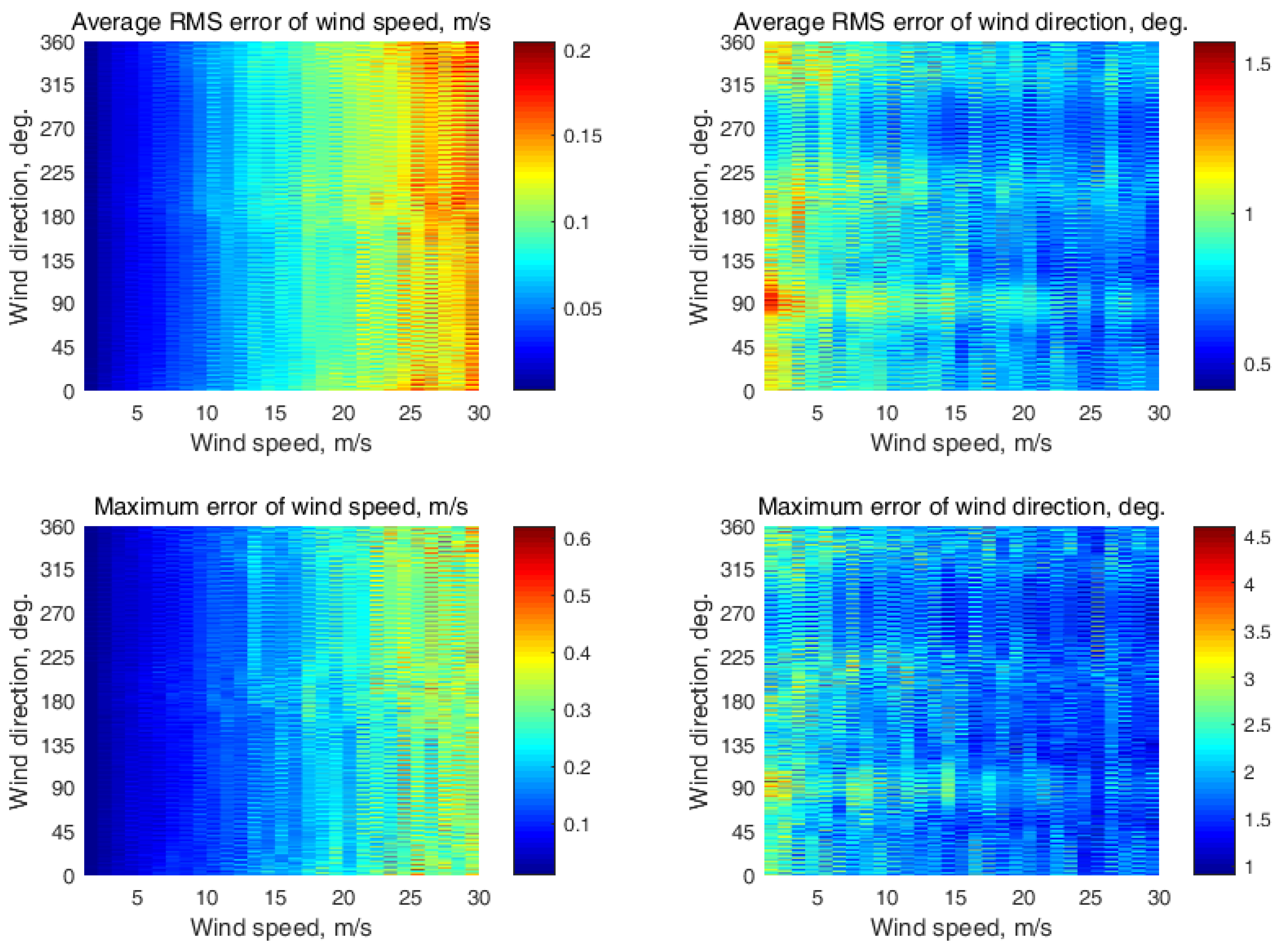
Here, we present the wind retrieval simulation results, when a single incidence angle is used along with the system of Equation set (6). The simulation as performed using the following conditions. The observed semicircular azimuth NRCS curve comprised N = 37 azimuth sectors. Each azimuth sector was of the 5° azimuth width and located at the directions from 0° to 180° relative to the flight direction (i.e., ground track) of aircraft with a 5° azimuth step. The simulation was completed with the assumption of 0.2 dB instrument noise and 261 NRCS samples integrated for each azimuth sector. The wind speed varied from 2 m/s to 30 m/s. The results obtained at the incidence angles from 30° to 60° with a 5° step are shown in Figure A2, Figure A3, Figure A4, Figure A5, Figure A6, Figure A7 and Figure A8.
Figure A2.
Semicircular wind retrieval results at a single 30° incidence angle.
Figure A2.
Semicircular wind retrieval results at a single 30° incidence angle.
Figure A3.
Semicircular wind retrieval results at a single 35° incidence angle.
Figure A3.
Semicircular wind retrieval results at a single 35° incidence angle.
Figure A4.
Semicircular wind retrieval results at a single 40° incidence angle.
Figure A4.
Semicircular wind retrieval results at a single 40° incidence angle.
Figure A5.
Semicircular wind retrieval results at a single 45° incidence angle.
Figure A5.
Semicircular wind retrieval results at a single 45° incidence angle.
Figure A6.
Semicircular wind retrieval results at a single 50° incidence angle.
Figure A6.
Semicircular wind retrieval results at a single 50° incidence angle.
Figure A7.
Semicircular wind retrieval results at a single 55° incidence angle.
Figure A7.
Semicircular wind retrieval results at a single 55° incidence angle.
Figure A8.
Semicircular wind retrieval results at a single 60° incidence angle.
Figure A8.
Semicircular wind retrieval results at a single 60° incidence angle.
Appendix C
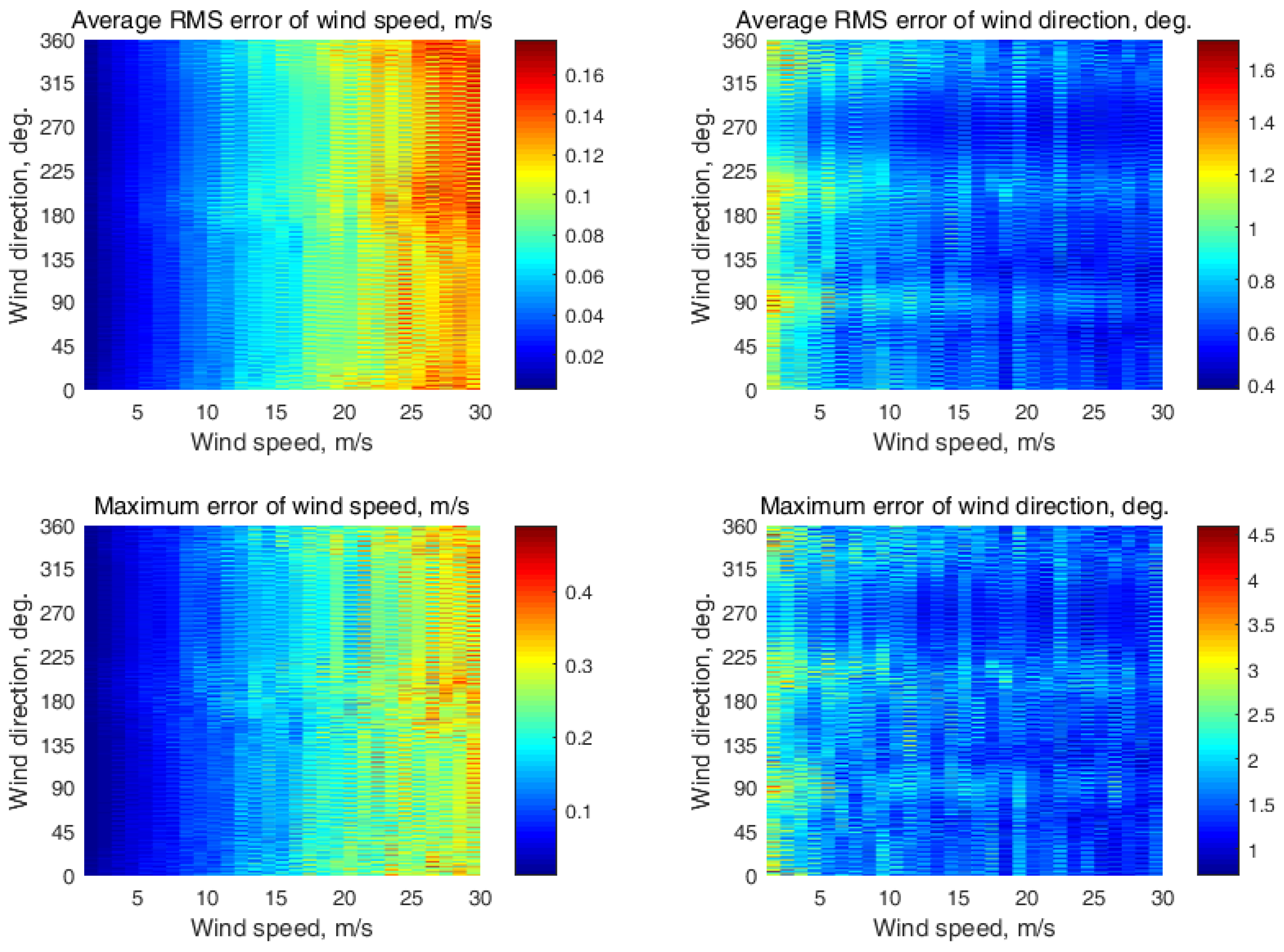
These are the wind retrieval simulation results when two neighboring incidence angles are simultaneously used along with the system of Equation set (6). The simulation was performed with the following conditions. The observed semicircular azimuth NRCS curve comprised N = 37 azimuth sectors. Each azimuth sector was of a 5° azimuth width and located at the directions from 0° to 180° relative to the flight direction (i.e., ground track) of aircraft with a 5° azimuth step. The simulation was completed with the assumption of 0.2 dB instrument noise and 261 NRCS samples integrated for each azimuth sector. The wind speed varied from 2 m/s to 30 m/s. The results obtained at the following two incidence angle combinations (30°, 35°); (35°, 40°); (40°, 45°); (45°, 50°); (50°, 55°); and (55°, 60°) are shown in Figure A9, Figure A10, Figure A11, Figure A12, Figure A13 and Figure A14.
Figure A9.
Semicircular wind retrieval results at the (30°, 35°) incidence angle combination.
Figure A9.
Semicircular wind retrieval results at the (30°, 35°) incidence angle combination.
Figure A10.
Semicircular wind retrieval results at the (35°, 40°) incidence angle combination.
Figure A10.
Semicircular wind retrieval results at the (35°, 40°) incidence angle combination.
Figure A11.
Semicircular wind retrieval results at the (40°, 45°) incidence angle combination.
Figure A11.
Semicircular wind retrieval results at the (40°, 45°) incidence angle combination.
Figure A12.
Semicircular wind retrieval results at the (45°, 50°) incidence angle combination.
Figure A12.
Semicircular wind retrieval results at the (45°, 50°) incidence angle combination.
Figure A13.
Semicircular wind retrieval results at the (50°, 55°) incidence angle combination.
Figure A13.
Semicircular wind retrieval results at the (50°, 55°) incidence angle combination.
Figure A14.
Semicircular wind retrieval results at the (55°, 60°) incidence angle combination.
Figure A14.
Semicircular wind retrieval results at the (55°, 60°) incidence angle combination.
Appendix D
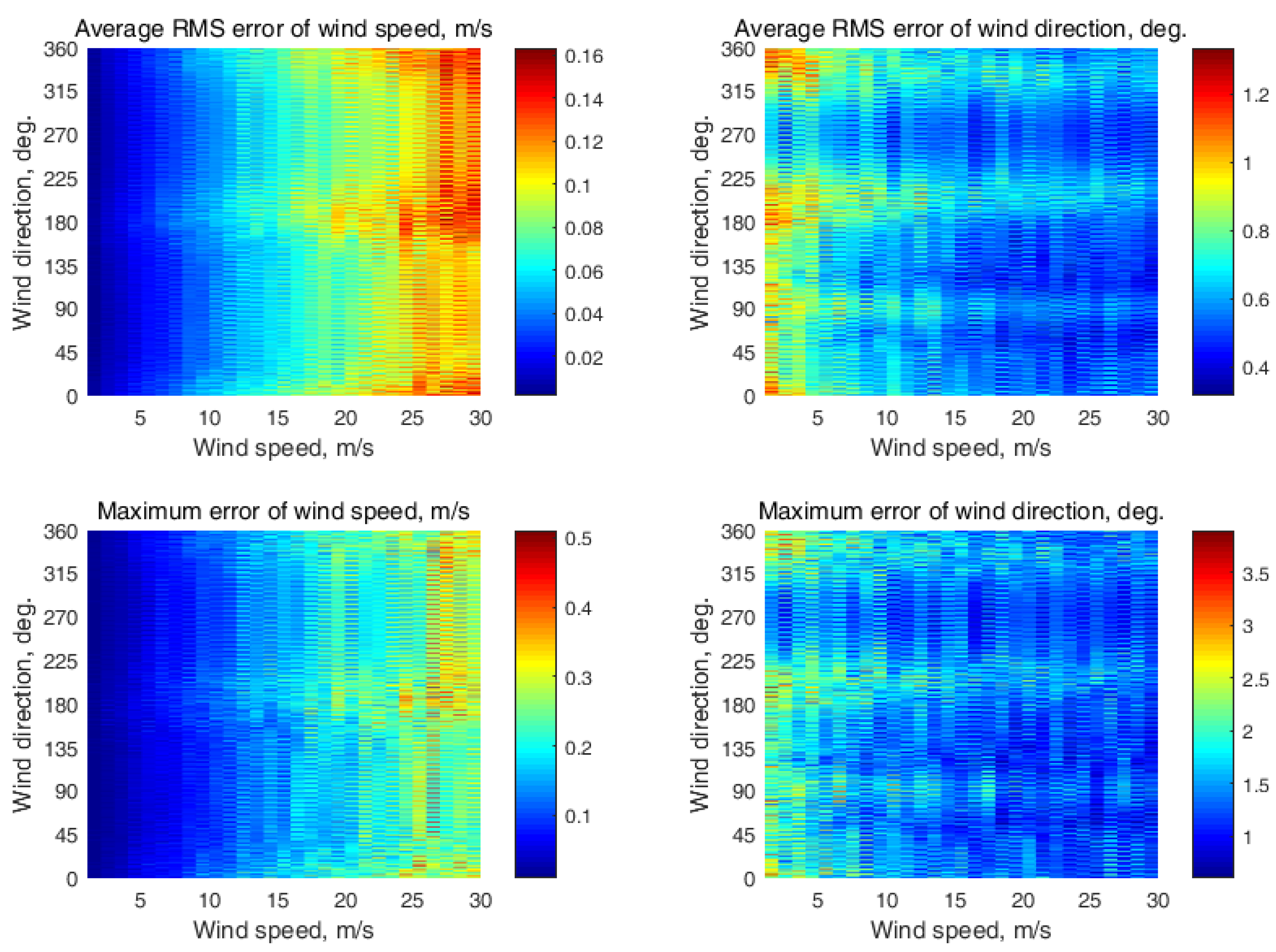
These are the wind retrieval simulation results when three neighboring incidence angles are simultaneously used along with the system of Equation set (6). The simulation was performed at the following conditions. The observed semicircular azimuth NRCS curve comprised N = 37 azimuth sectors. Each azimuth sector was of a 5° azimuth width and located at the directions from 0° to 180° relative to the flight direction (i.e., ground track) of aircraft with a 5° azimuth step. The simulation was completed with the assumption of 0.2 dB instrument noise and 261 NRCS samples integrated for each azimuth sector. The wind speed varied from 2 m/s to 30 m/s. The results obtained at the following three incidence angle combinations (30°, 35°, 40°); (35°, 40°, 45°); (40°, 45°, 50°); (45°, 50°, 55°); and (50°, 55°, 60°) are shown in Figure A15, Figure A16, Figure A17, Figure A18 and Figure A19.
Figure A15.
Semicircular wind retrieval results at the (30°, 35°, 40°) incidence angle combination.
Figure A15.
Semicircular wind retrieval results at the (30°, 35°, 40°) incidence angle combination.
Figure A16.
Semicircular wind retrieval results at the (35°, 40°, 45°) incidence angle combination.
Figure A16.
Semicircular wind retrieval results at the (35°, 40°, 45°) incidence angle combination.
Figure A17.
Semicircular wind retrieval results at the (40°, 45°, 50°) incidence angle combination.
Figure A17.
Semicircular wind retrieval results at the (40°, 45°, 50°) incidence angle combination.
Figure A18.
Semicircular wind retrieval results at the (45°, 50°, 55°) incidence angle combination.
Figure A18.
Semicircular wind retrieval results at the (45°, 50°, 55°) incidence angle combination.
Figure A19.
Semicircular wind retrieval results at the (50°, 55°, 60°) incidence angle combination.
Figure A19.
Semicircular wind retrieval results at the (50°, 55°, 60°) incidence angle combination.
Appendix E
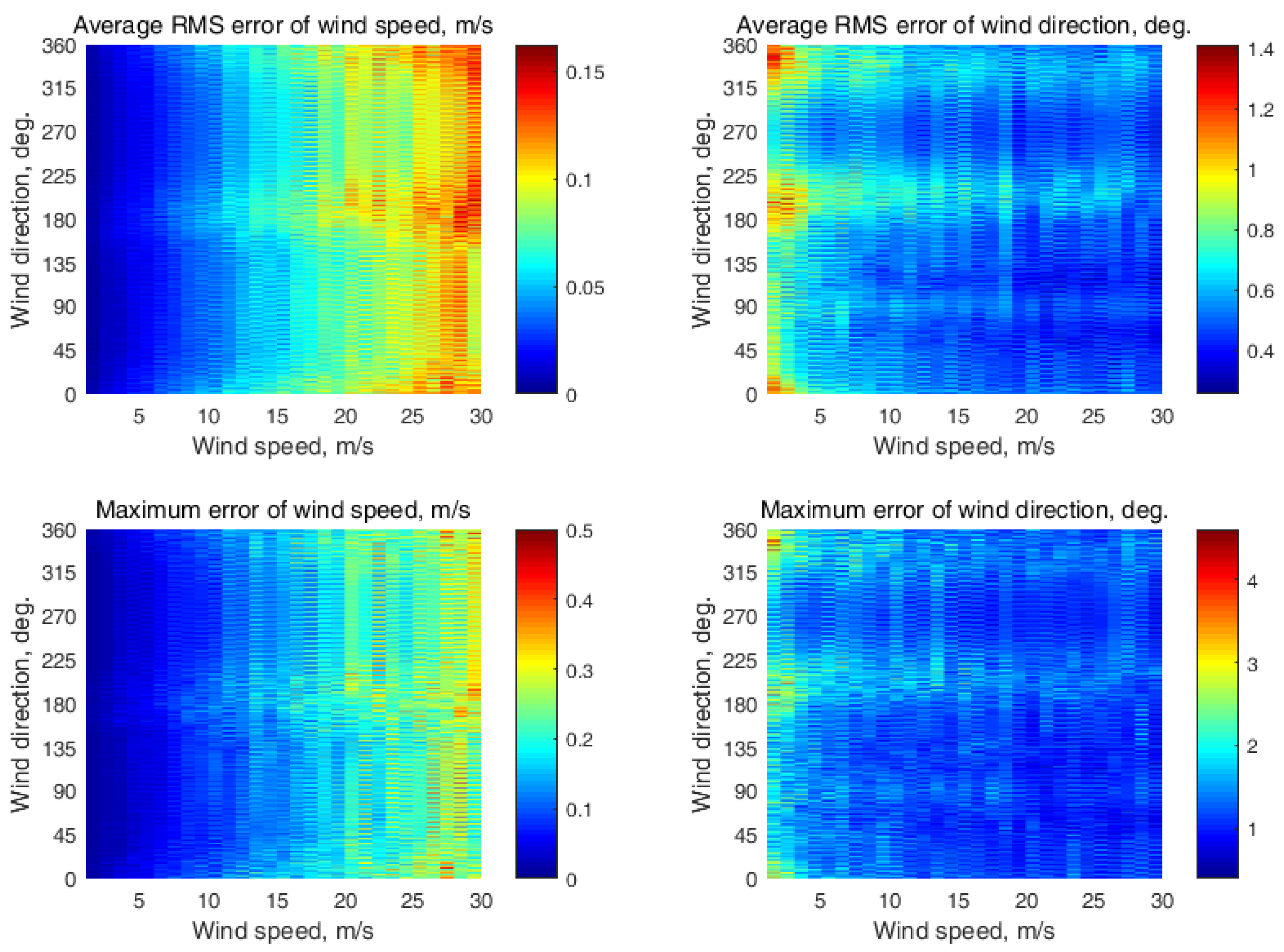
These are the wind retrieval simulation results when four neighboring incidence angles are simultaneously used along with the system of Equation set (6). The simulation was performed with the following conditions. The observed semicircular azimuth NRCS curve comprised N = 37 azimuth sectors. Each azimuth sector was of a 5° azimuth width and located at the directions from 0° to 180° relative to the flight direction (i.e., ground track) of aircraft with a 5° azimuth step. The simulation was completed with the assumption of 0.2 dB instrument noise and 261 NRCS samples integrated for each azimuth sector. The wind speed varied from 2 m/s to 30 m/s. The results obtained at the following four incidence angle combinations (30°, 35°, 40°, 45°); (35°, 40°, 45°, 50°); (40°, 45°, 50°, 55°); and (45°, 50°, 55°, 60°) are shown in Figure A20, Figure A21, Figure A22 and Figure A23.
Figure A20.
Semicircular wind retrieval results at the (30°, 35°, 40°, 45°) incidence angle combination.
Figure A20.
Semicircular wind retrieval results at the (30°, 35°, 40°, 45°) incidence angle combination.
Figure A21.
Semicircular wind retrieval results at the (35°, 40°, 45°, 50°) incidence angle combination.
Figure A21.
Semicircular wind retrieval results at the (35°, 40°, 45°, 50°) incidence angle combination.
Figure A22.
Semicircular wind retrieval results at the (40°, 45°, 50°, 55°) incidence angle combination.
Figure A22.
Semicircular wind retrieval results at the (40°, 45°, 50°, 55°) incidence angle combination.
Figure A23.
Semicircular wind retrieval results at the (45°, 50°, 55°, 60°) incidence angle combination.
Figure A23.
Semicircular wind retrieval results at the (45°, 50°, 55°, 60°) incidence angle combination.
Appendix F
These are the wind retrieval simulation results when seven neighboring incidence angles are simultaneously used along with the system of Equation set (6). The simulation was performed with the following conditions. The observed semicircular azimuth NRCS curve comprised N = 37 azimuth sectors. Each azimuth sector was of a 5° azimuth width and located at the directions from 0° to 180° relative to the flight direction (i.e., ground track) of aircraft with a 5° azimuth step. The simulation was completed with the assumption of 0.2 dB instrument noise and 261 NRCS samples integrated for each azimuth sector. The wind speed varied from 2 m/s to 30 m/s. The results obtained at the seven incidence angle combination (30°, 35°, 40°, 45°, 50°, 55°, 60°) are shown in Figure A24.
Figure A24.
Semicircular wind retrieval results at the (30°, 35°, 40°, 45°, 50°, 55°, 60°) incidence angle combination.
Figure A24.
Semicircular wind retrieval results at the (30°, 35°, 40°, 45°, 50°, 55°, 60°) incidence angle combination.
Appendix G
These are the wind retrieval simulation results with three neighboring incidence angles when the highest 15° difference of the incidence angle between the neighboring incidence angles in the given incidence angles’ range from 30° to 60° takes place and the system of Equation set (6) is used. The simulation was performed with the following conditions. The observed semicircular azimuth NRCS curve comprised N = 37 azimuth sectors. Each azimuth sector was of a 5° azimuth width and located at the directions from 0° to 180° relative to the flight direction (i.e., ground track) of aircraft with a 5° azimuth step. The simulation was completed with the assumption of 0.2 dB instrument noise and 261 NRCS samples integrated for each azimuth sector. The wind speed varied from 2 m/s to 30 m/s. The results obtained at the three incidence angles of 30°, 45°, and 60° are shown in Figure A25.
Figure A25.
Semicircular wind retrieval results at the (30°, 45°, 60°) incidence angle combination.
Figure A25.
Semicircular wind retrieval results at the (30°, 45°, 60°) incidence angle combination.
References
Kramer, H.J. Observation of the Earth and Its Environment: Survey of Missions and Sensors, 4th ed.; Springer: Berlin/Heidelberg, Germany, 2002; p. 1509. [Google Scholar] [CrossRef] [Green Version]
Moore, R.K.; Fung, A.K. Radar determination of winds at sea. Proc. IEEE1979, 67, 1504–1521. [Google Scholar] [CrossRef]
Masuko, H.; Okamoto, K.; Shimada, M.; Niwa, S. Measurement of microwave backscattering signatures of the ocean surface using X band and Ka band airborne scatterometers. J. Geophys. Res. Ocean.1986, 91, 13065–13083. [Google Scholar] [CrossRef]
Nekrasov, A.; De Wit, J.J.M.; Hoogeboom, P. FM-CW millimeter wave demonstrator system as a sensor of the sea surface wind vector. IEICE Electron.2004, 1, 137–143. [Google Scholar] [CrossRef] [Green Version]
Nekrasov, A. Airborne Doppler navigation system application for measurement of the water surface backscattering signature. In Proceedings of the ISPRS TC VII Symposium—100 Years ISPRS, Vienna, Austria, 5–7 July 2010; The International Archives of the Photogrammetry, Remote Sensing and Spatial Information Sciences. Wagner, W., Székely, B., Eds.; 2010; pp. 163–168. Available online: https://www.isprs.org/proceedings/XXXVIII/part7/a/pdf/163_XXXVIII-part7A.pdf (accessed on 13 February 2023).
Nekrasov, A. Measuring the sea surface wind vector by the Doppler navigation system of flying apparatus having the track-stabilized four-beam antenna. In Proceedings of the 17th Asia Pacific Microwave Conference (APMC), Suzhou, China, 4–7 December 2005; Volume 1, pp. 645–647. [Google Scholar] [CrossRef]
Tanelli, S.; Durden, S.L.; Im, E. Simultaneous measurements of Ku- and Ka-band sea surface cross sections by an airborne radar. IEEE Geosci. Remote Sens. Lett.2006, 3, 359–363. [Google Scholar] [CrossRef]
Nekrasov, A.; Gamcová, M.; Kurdel, P.; Labun, J. On off-nadir wind retrieval over the sea surface using APR-2 or similar radar geometry. Int. J. Remote Sens.2018, 39, 5934–5942. [Google Scholar] [CrossRef]
Nekrasov, A.; Khachaturian, A.; Veremyev, V.; Bogachev, M. Sea surface wind measurement by airborne weather radar scanning in a wide-size sector. Atmosphere2016, 7, 72. [Google Scholar] [CrossRef] [Green Version]
Wismann, V. Ocean windfield measurements with a rotating antenna airborne C-band scatterometer. In Proceedings of the 12th Canadian Symposium on Remote Sensing Geoscience and Remote Sensing Symposium, Vancouver, BC, Canada, 10–14 July 1989; pp. 1470–1473. [Google Scholar] [CrossRef]
Fernandez, D.E.; Kerr, E.; Castells, A.; Frasier, S.; Carswell, J.; Chang, P.S.; Black, P.; Marks, F. IWRAP: The Imaging Wind and Rain Airborne Profiler for remote sensing of the ocean and the atmospheric boundary layer within tropical cyclones. IEEE Trans. Geosci. Remote Sens.2005, 43, 1775–1787. [Google Scholar] [CrossRef]
Guimond, S.R.; Tian, L.; Heymsfield, G.M.; Frasier, S.J. Wind retrieval algorithms for the IWRAP and HIWRAP airborne Doppler radars with applications to hurricanes. J. Atmos. Ocean. Technol.2014, 31, 1189–1215. [Google Scholar] [CrossRef] [Green Version]
Hildebrand, P.H. Estimation of sea-surface wind using backscatter cross-section measurements from airborne research weather radar. IEEE Trans. Geosci. Remote Sens.1994, 32, 110–117. [Google Scholar] [CrossRef]
Karaev, V.Y.; Kanevsky, M.B.; Balandina, G.N.; Meshkov, E.M.; Challenor, P.; Srokosz, M.; Gommenginger, C. A rotating knife-beam altimeter for wide-swath remote sensing of ocean: Wind and waves. Sensors2006, 6, 620–642. [Google Scholar] [CrossRef] [Green Version]
Nekrasov, A.; Khachaturian, A. Towards the sea wind measurement with the airborne scatterometer having the rotating-beam antenna mounted over fuselage. Remote Sens.2021, 13, 5165. [Google Scholar] [CrossRef]
Nekrasov, A.; Khachaturian, A.; Vorobev, E. Optimization of the NRCS sampling at the sea wind retrieval by the airborne rotating-beam scatterometer mounted under fuselage. Sensors2022, 22, 4016. [Google Scholar] [CrossRef] [PubMed]
Nekrasov, A.; Veremyev, V. Airborne weather radar concept for measuring water surface backscattering signature and sea wind at circular flight. Nase More2016, 63, 278–282. [Google Scholar] [CrossRef]
Nekrassov, A. Measurement of sea surface wind speed and its navigational direction from flying apparatus. In Proceedings of the MTS/IEEE Conference Oceans’97, Halifax, NS, Canada, 6–9 October 1997; pp. 83–86. [Google Scholar] [CrossRef]
Khachaturian, A.B.; Nekrasov, A.V.; Bogachev, M.I. Sea wind parameters retrieval using Y-configured Doppler navigation system data. Performance and accuracy. J. Phys. Conf. Ser.2018, 1015, 032058. [Google Scholar] [CrossRef] [Green Version]
Nekrasov, A.; Khachaturian, A.; Gamcová, M.; Kurdel, P.; Obukhovets, V.; Veremyev, V.; Bogachev, M. Sea wind measurement by Doppler navigation system with X-configured beams in rectilinear flight. Remote Sens.2017, 9, 887. [Google Scholar] [CrossRef] [Green Version]
Nekrasov, A. On possibility to measure the sea surface wind vector by the Doppler navigation system of flying apparatus. In Proceedings of the IEEE International Radar Conference RADAR 2005, Arlington, VA, USA, 9–12 May 2005; pp. 747–752. [Google Scholar] [CrossRef]
Nekrasov, A.; Ouellette, J.D.; Majurec, N.; Johnson, J.T. A study of sea surface wind vector estimation from near nadiral cross-track-scanned backscatter data. IEEE Geosci. Remote Sens. Lett.2013, 10, 1503–1506. [Google Scholar] [CrossRef]
Durden, S.L.; Li, L.; Im, E.; Yueh, S.H. A surface reference technique for airborne Doppler radar measurements in hurricanes. J. Atmos. Ocean. Technol.2003, 20, 269–275. [Google Scholar] [CrossRef]
Nekrasov, A. Water-surface wind vector estimation by an airborne weather radar having a medium-size scanning sector. In Proceedings of the 14th International Radar Symposium IRS 2013, Dresden, Germany, 19–21 June 2013; Volume 2, pp. 1079–1084. Available online: https://ieeexplore.ieee.org/document/6581724 (accessed on 13 February 2023).
Nekrasov, A.; Popov, D. A concept for measuring the water-surface backscattering signature by airborne weather radar. In Proceedings of the 16th International Radar Symposium IRS 2015, Dresden, Germany, 24–26 June 2015; Volume 2, pp. 1112–1116. [Google Scholar] [CrossRef]
McLaughlin, D.J.; McIntosh, R.E.; Pazmany, A.; Hevizi, L.; Boltniew, E. A C-band scatterometer for remote sensing the air-sea interface. IEEE Trans. Geosci. Remote Sens.1991, 29, 260–267. [Google Scholar] [CrossRef]
Li, L.; Heymsfield, G.; Carswell, J.; Schaubert, D.H.; McLinden, M.L.; Creticos, J.; Perrine, M.; Coon, M.; Cervantes, J.I.; Vega, M.; et al. The NASA high-altitude imaging wind and rain airborne profiler. IEEE Trans. Geosci. Remote Sens.2016, 54, 298–310. [Google Scholar] [CrossRef]
Nekrasov, A.; Khachaturian, A.; Fidge, C. Using semicircular sampling to increase sea-wind retrieval altitude with a high-altitude UAV scatterometer. Drones2022, 6, 223. [Google Scholar] [CrossRef]
Njoku, E.G. Encyclopedia of Remote Sensing; Springer: New York, NY, USA, 2014; p. 939. ISBN 978-0-387-36700-2. [Google Scholar]
Nekrassov, A. Sea surface wind vector measurement by airborne scatterometer having wide-beam antenna in horizontal plane. In Proceedings of the IGARSS’99, Hamburg, Germany, 28 June–2 July 1999; Volume 2, pp. 1001–1003. [Google Scholar] [CrossRef]
Nekrassov, A. On airborne measurement of the sea surface wind vector by a scatterometer (altimeter) with a nadir-looking wide-beam antenna. IEEE Trans. Geosci. Remote Sens.2002, 40, 2111–2116. [Google Scholar] [CrossRef]
Spencer, M.W.; Graf, J.E. The NASA scatterometer (NSCAT) mission. Backscatter1997, 8, 18–24. [Google Scholar]
Nghiem, S.V.; Li, F.K.; Neumann, G. The dependence of ocean backscatter at Ku-band on oceanic and atmospheric parameters. IEEE Trans. Geosci. Remote Sens.1997, 35, 581–600. [Google Scholar] [CrossRef]
Hans, P. Auslegung und Analyse von Satellitengetragenen Mikrowellensensorsystemen zur Windfeldmessung (Scatterometer) über dem Meer und Vergleich der Meßverfahren in Zeit- und Frequenzebene. Von der Fakultät 2 Bauingenieur- und Vermessungswesen der Universität Stuttgart zur Erlangung der Würde eines Doktor-Ingenieurs Genehmigte Abhandlung; Institut für Navigation der Universität Stuttgart: Stuttgart, Germany, 1987; p. 225S. (In German) [Google Scholar]
Nekrasov, A.; Khachaturian, A.; Veremyev, V.; Bogachev, M. Doppler navigation system with a non-stabilized antenna as a sea-surface wind sensor. Sensors2017, 17, 1340. [Google Scholar] [CrossRef] [Green Version]
Ulaby, F.T.; Long, D.G. Microwave Radar and Radiometric Remote Sensing; University of Michigan Press: Ann Arbor, MI, USA, 2014; p. 1116. ISBN 978-0-472-11935-6. [Google Scholar]
Lin, W.; Portabella, M.; Stoffelen, A.; Verhoef, A. On the characteristics of ASCAT wind direction ambiguities. Atmos. Meas. Tech.2013, 6, 1053–1060. [Google Scholar] [CrossRef] [Green Version]
Komen, G.J.; Cavaleri, L.; Donelan, M.; Hasselmann, K.; Hasselmann, S.; Janssen, P.A.E.M. Dynamics and Modelling of Ocean Waves; Cambridge University Press: Cambridge, UK, 1994; p. 532. [Google Scholar]
Figure 1.
Geometry of a scatterometer with a rotating two-beam antenna: V is the flight speed; H is the altitude; θ1 and θ2 are the incidence angles of antenna beams 1 and 2; ψ is the aircraft’s flight direction counted clockwise from the north.
Figure 1.
Geometry of a scatterometer with a rotating two-beam antenna: V is the flight speed; H is the altitude; θ1 and θ2 are the incidence angles of antenna beams 1 and 2; ψ is the aircraft’s flight direction counted clockwise from the north.
Figure 2.
The maximum altitude of the wind retrieval method’s applicability depending on the azimuth NRCS sampling scheme and the incidence angle.
Figure 2.
The maximum altitude of the wind retrieval method’s applicability depending on the azimuth NRCS sampling scheme and the incidence angle.
Figure 3.
Schematic view of the incidence angle combinations’ geometries at the right-side semicircular NRCS sampling scheme in the given incidence angles’ range from 30° to 60°: (a) single incidence angle case; (b) case of 2 neighboring incidence angles; (c) case of 3 neighboring incidence angles; (d) case of 4 neighboring incidence angles; (e) case of 7 neighboring incidence angles; (f) particular case of 3 incidence angles of 30°, 45°, and 60°.
Figure 4.
Semicircular NRCS sampling scheme results: (a) wind speed maximum error; (b) wind direction maximum error. The black asterisks are for the case of a single incidence angle; the blue lines are for the case of 2 incidence angles; the purple lines are for the case of 3 incidence angles; the green lines are for the case of 4 incidence angles; the red line is for the case of 7 incidence angles; and the black, dashed line with dots is for the particular case of 3 incidence angles of 30°, 45°, and 60°.
Figure 5.
Circular NRCS sampling scheme results: (a) wind speed maximum error; (b) wind direction maximum error. The black asterisks are for the case of a single incidence angle; the blue lines are for the case of 2 incidence angles; the purple lines are for the case of 3 incidence angles; the green lines are for the case of 4 incidence angles; the red line is for the case of 7 incidence angles; and the black, dashed line with dots is for the particular case of the 3 incidence angles of 30°, 45°, and 60° [17].
Disclaimer/Publisher’s Note: The statements, opinions and data contained in all publications are solely those of the individual author(s) and contributor(s) and not of MDPI and/or the editor(s). MDPI and/or the editor(s) disclaim responsibility for any injury to people or property resulting from any ideas, methods, instructions or products referred to in the content.
Nekrasov, A.; Khachaturian, A.; Fidge, C.
Optimization of Airborne Scatterometer NRCS Semicircular Sampling for Sea Wind Retrieval. Remote Sens.2023, 15, 1613.
https://doi.org/10.3390/rs15061613
AMA Style
Nekrasov A, Khachaturian A, Fidge C.
Optimization of Airborne Scatterometer NRCS Semicircular Sampling for Sea Wind Retrieval. Remote Sensing. 2023; 15(6):1613.
https://doi.org/10.3390/rs15061613
Chicago/Turabian Style
Nekrasov, Alexey, Alena Khachaturian, and Colin Fidge.
2023. "Optimization of Airborne Scatterometer NRCS Semicircular Sampling for Sea Wind Retrieval" Remote Sensing 15, no. 6: 1613.
https://doi.org/10.3390/rs15061613
Note that from the first issue of 2016, this journal uses article numbers instead of page numbers. See further details here.
Article Metrics
No
No
Article Access Statistics
For more information on the journal statistics, click here.
Multiple requests from the same IP address are counted as one view.
Nekrasov, A.; Khachaturian, A.; Fidge, C.
Optimization of Airborne Scatterometer NRCS Semicircular Sampling for Sea Wind Retrieval. Remote Sens.2023, 15, 1613.
https://doi.org/10.3390/rs15061613
AMA Style
Nekrasov A, Khachaturian A, Fidge C.
Optimization of Airborne Scatterometer NRCS Semicircular Sampling for Sea Wind Retrieval. Remote Sensing. 2023; 15(6):1613.
https://doi.org/10.3390/rs15061613
Chicago/Turabian Style
Nekrasov, Alexey, Alena Khachaturian, and Colin Fidge.
2023. "Optimization of Airborne Scatterometer NRCS Semicircular Sampling for Sea Wind Retrieval" Remote Sensing 15, no. 6: 1613.
https://doi.org/10.3390/rs15061613
Note that from the first issue of 2016, this journal uses article numbers instead of page numbers. See further details here.


