
Estimation of Ground Subsidence Deformation Induced by Underground Coal Mining with GNSS-IR

 , and
, and 
Abstract
: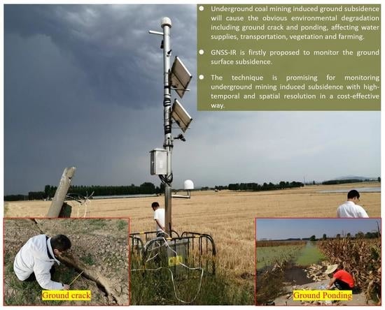
1. Introduction
- (a)
- Exploration of a new low-cost subsidence monitoring technique based on GNSS-IR;
- (b)
- Establishment of the mathematic model and estimating algorithm for the GNSS-IR based subsidence retrieval; and
- (c)
- Validation and analyzation of the initial results derived from the GNSS-IR ground subsidence monitoring technique.
2. Materials
2.1. Application of GNSS Analysis in Crust Monitoring
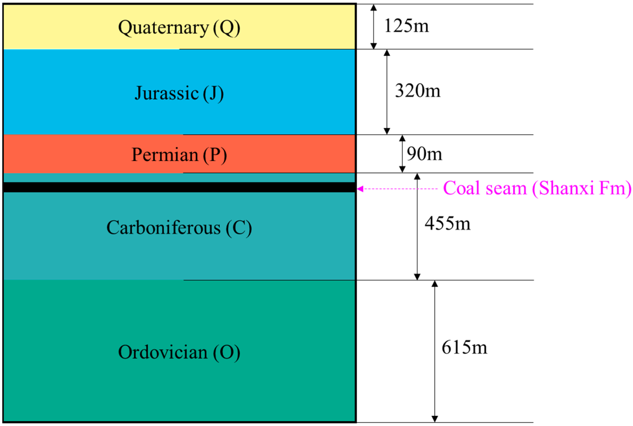
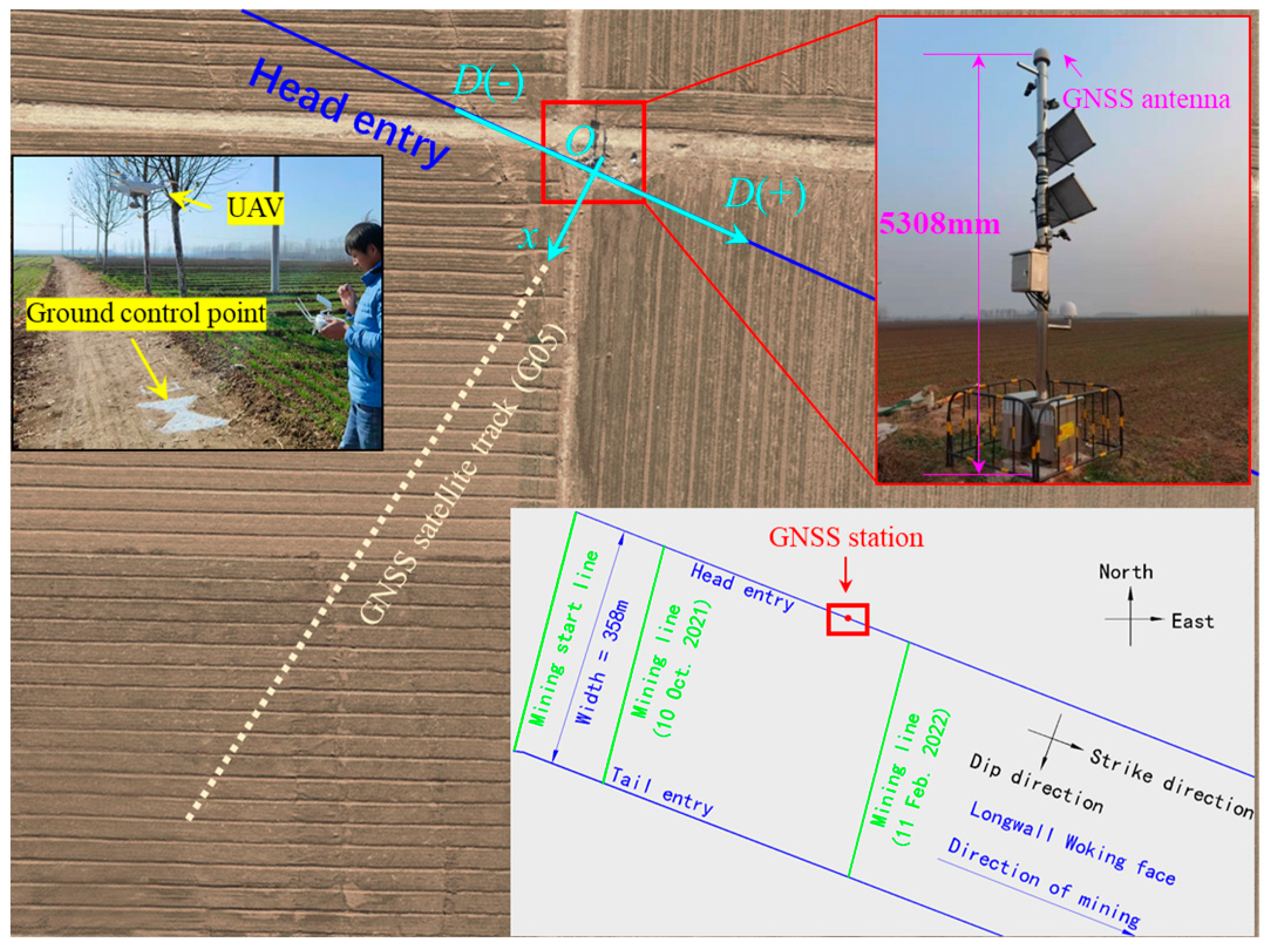
2.2. Geological Regime
3. Methods
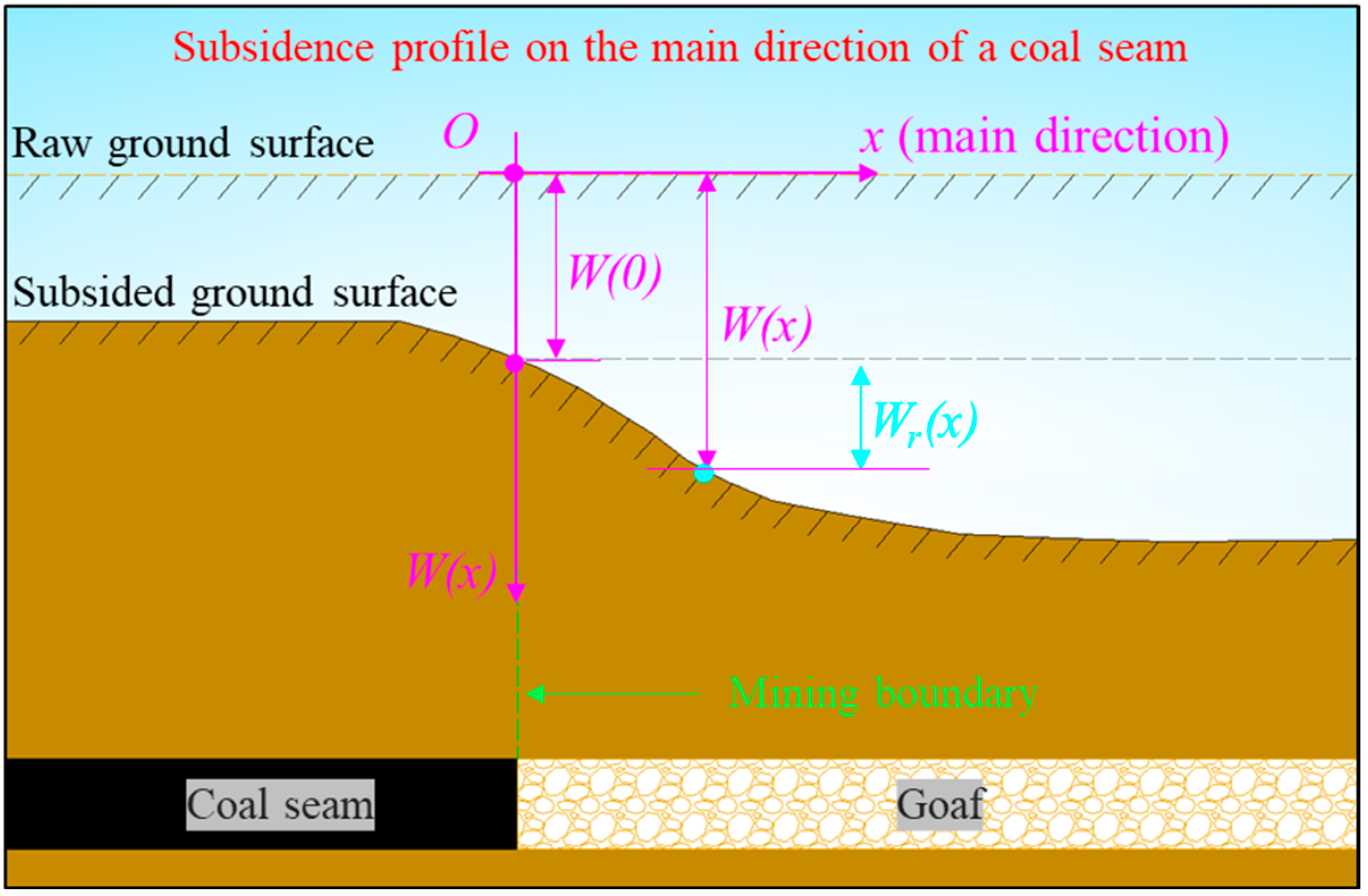
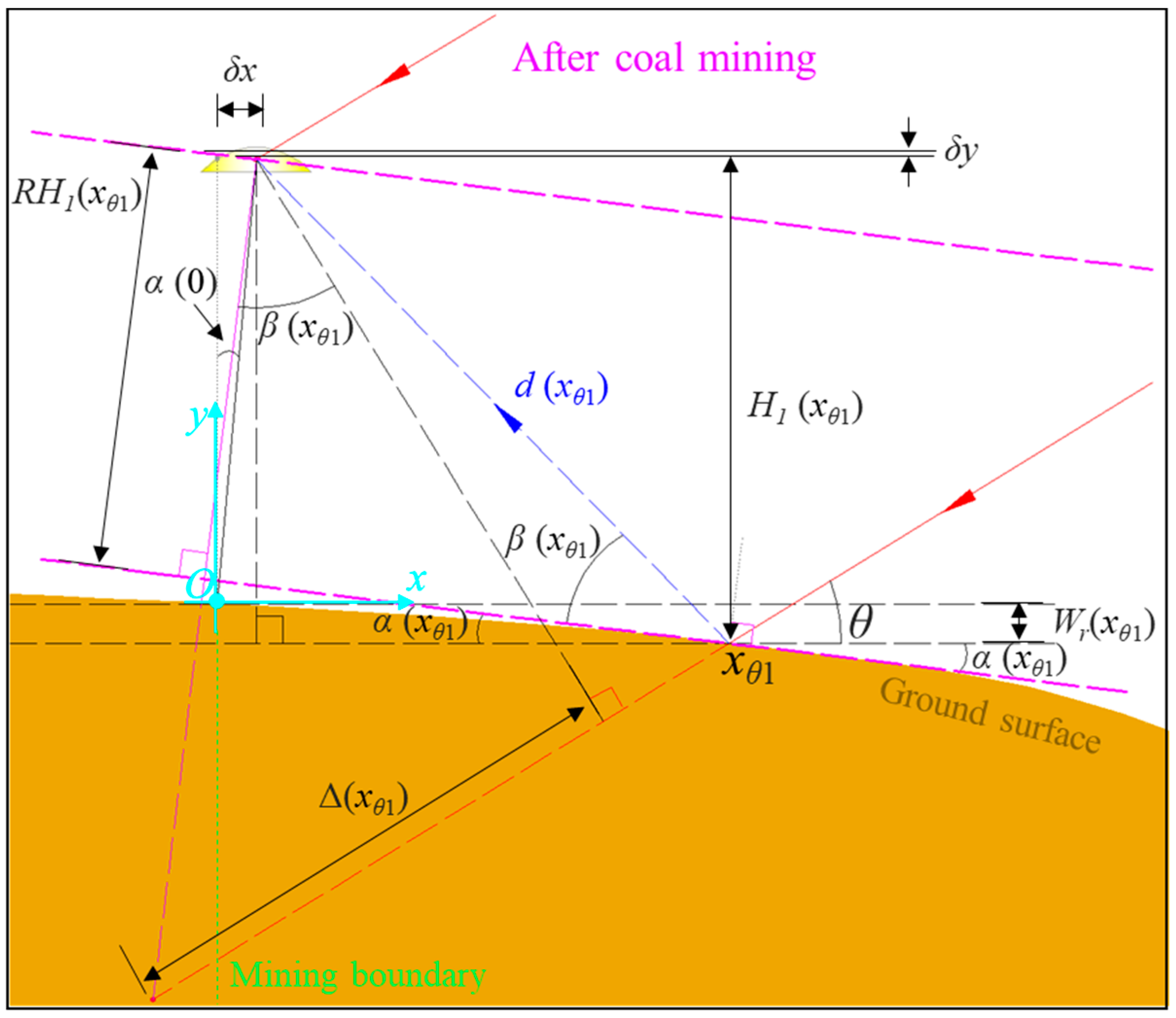
3.1. Mathematical Model of Ground Sudidence on the Main Direction of a Coal Seam
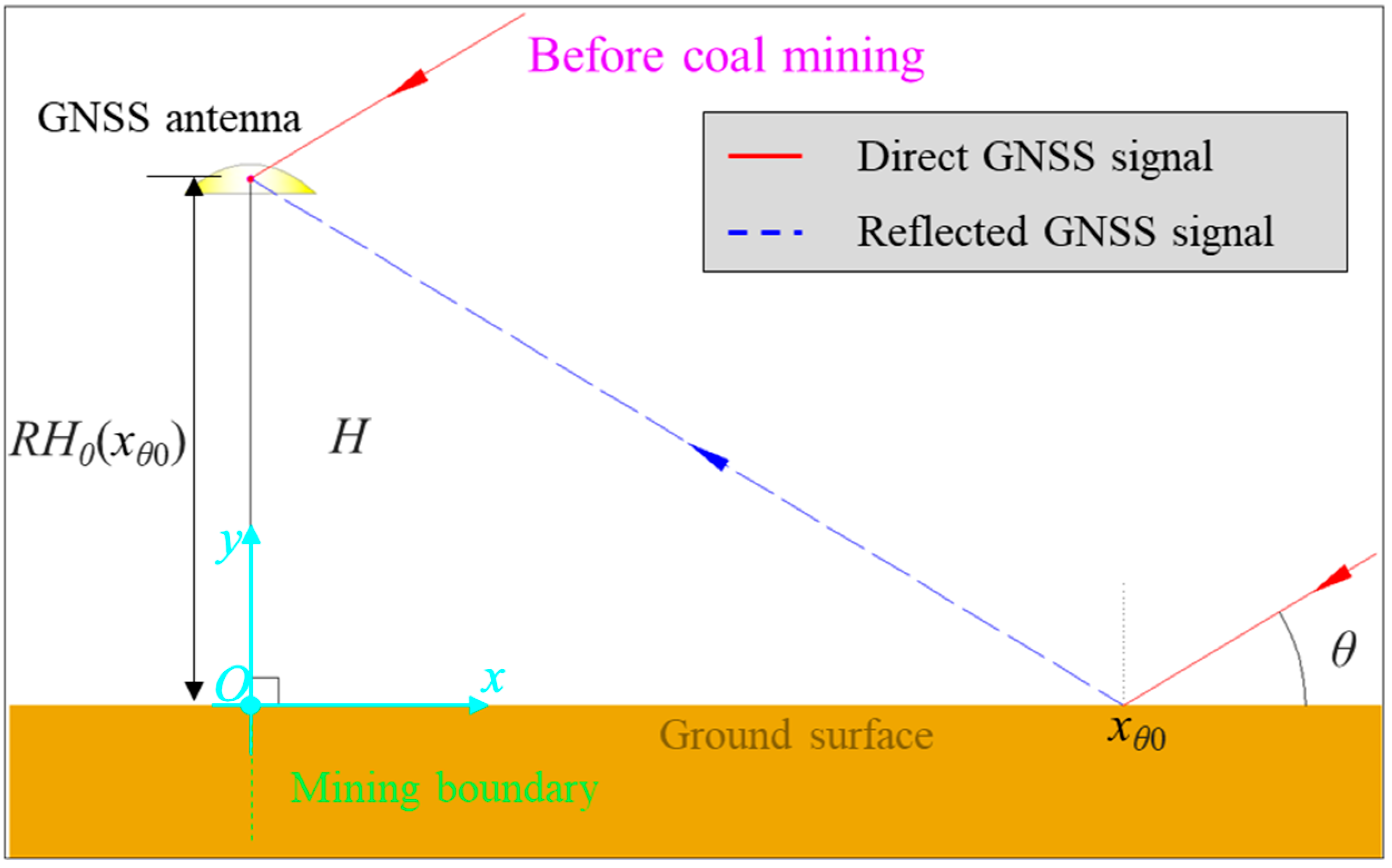
3.2. GNSS Reflection Model for Subsided Ground Surface
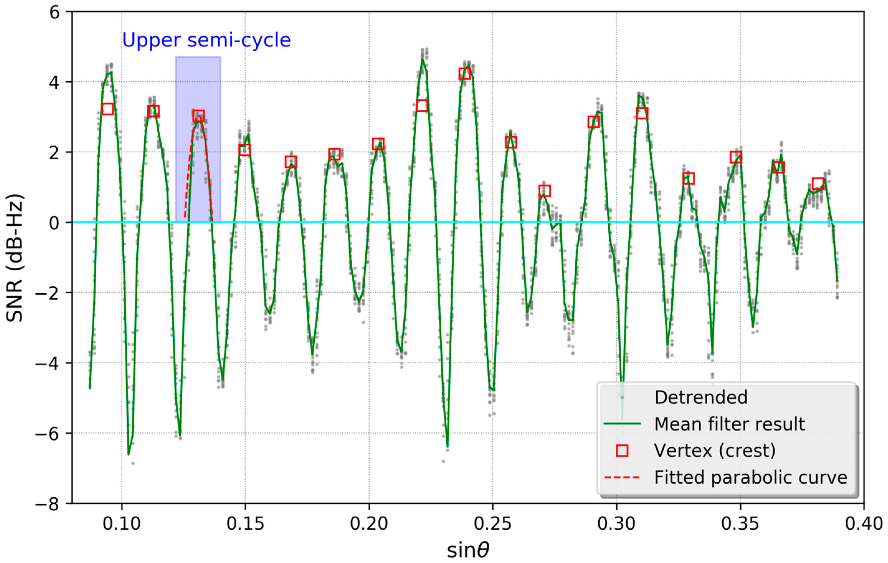
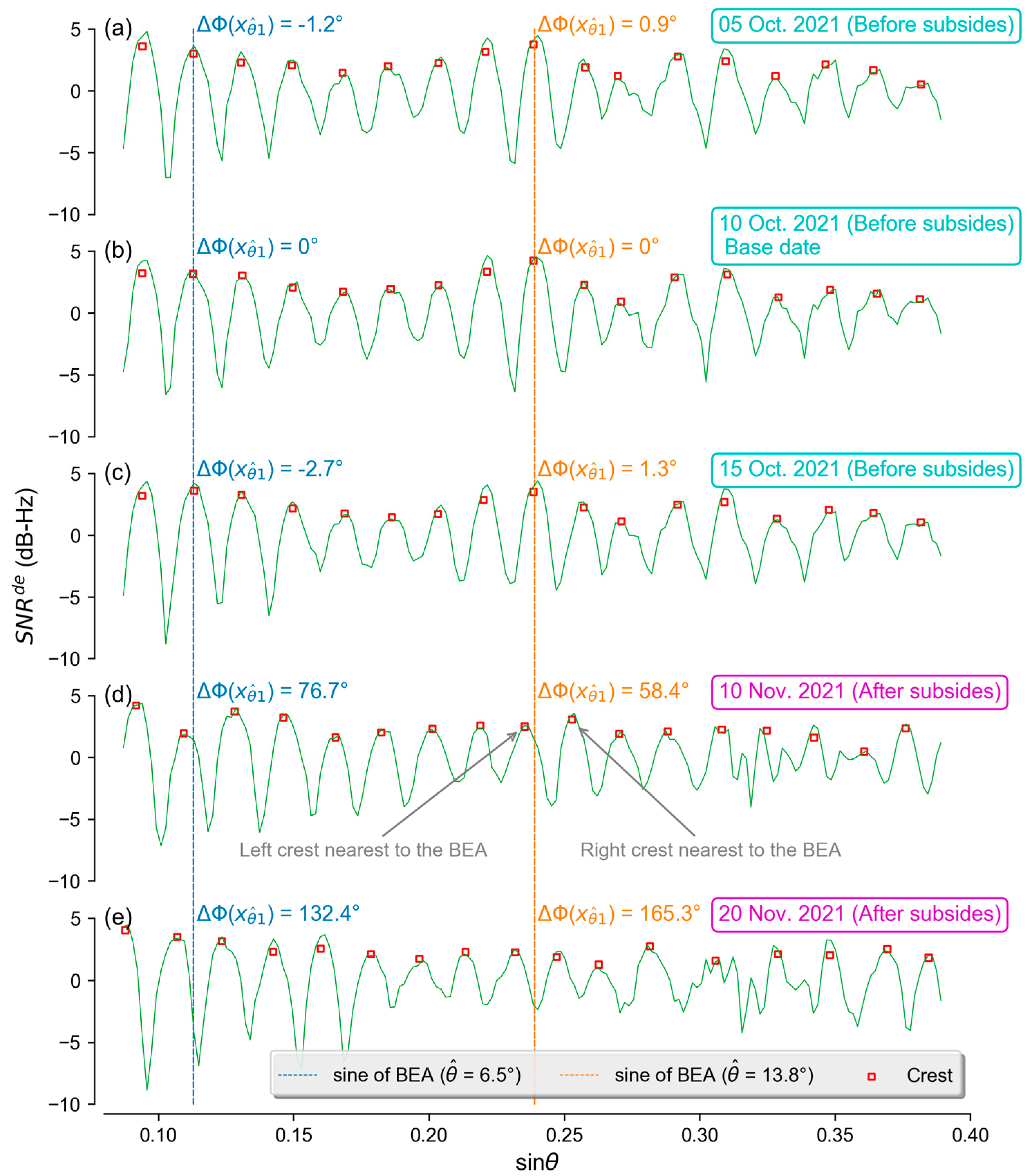
3.3. Phase Variation of the Detrended SNR Series Induced by Ground Subsidence
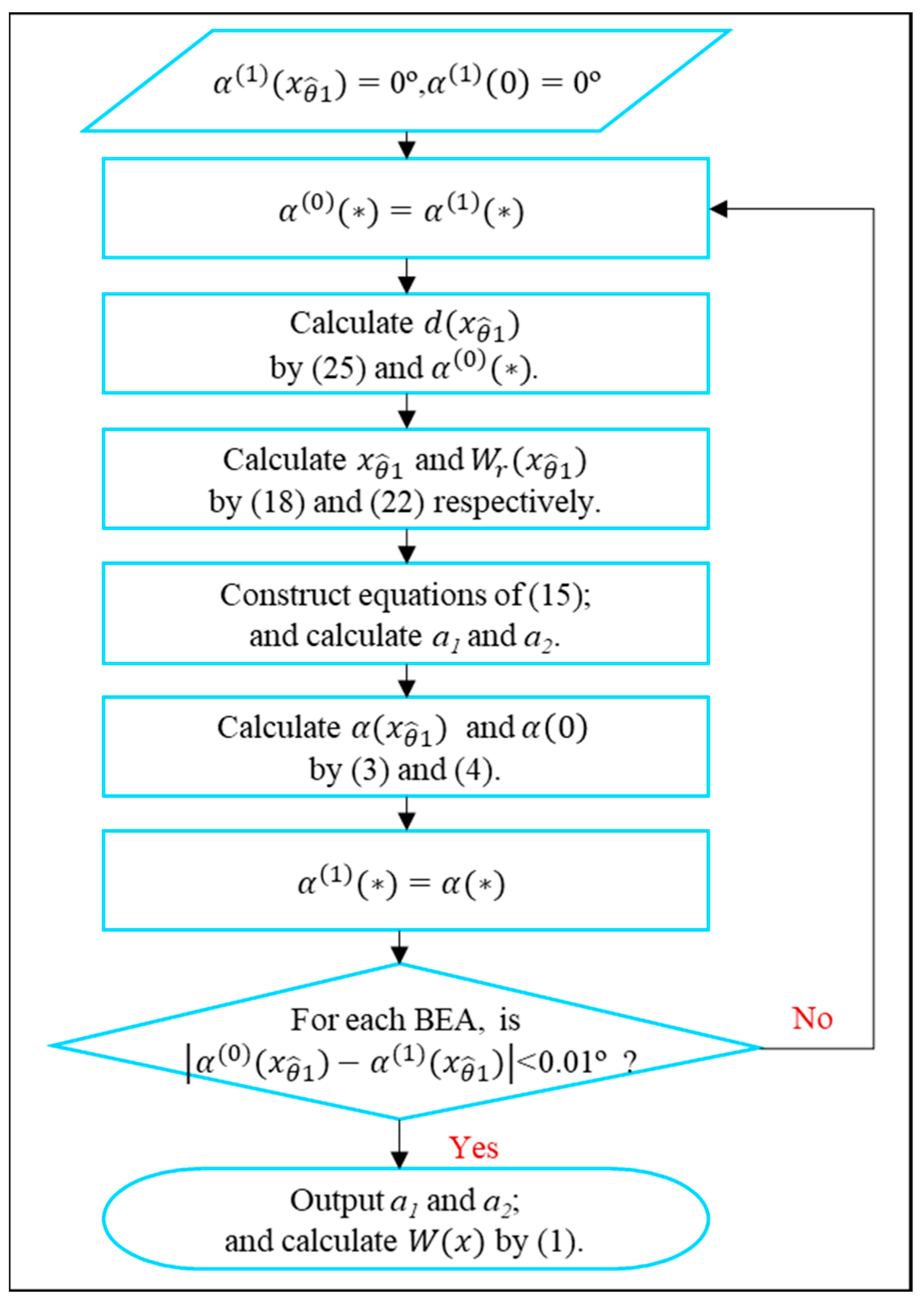
3.4. Estimation of Ground Subsidence with MRPV
- (a)
- Set initial value of tilt angle equal to 0° for each BEA;
- (b)
- Use initial value of tilt angle and MRPV calculating distance from the ground reflection point to the GNSS antenna through (25); Note that, height of the GNSS antenna in (25) can be obtained by exploiting Lomb–Scargle spectral analysis to the detrended SNR series collected on the base date;
- (c)
- Calculate the horizontal position and relative subsidence of the reflection point using (18) and (22), respectively;
- (d)
- Construct equation of (15) using horizontal position and relative subsidence derived from (c); and calculate the optimal PIM coefficients;
- (e)
- Calculate the tilt angle using the optimal PIM coefficients derived from (d) through equations of (3) and (4);
- (f)
- For each BEA, judge absolute error between the initial tilt angle and the angle derived from (e);
- (g)
- For each BEA, if the absolute error is less than 0.01°, which corresponds to ground tilt of about 0.2 mm/m, output the optimal PIM coefficients and calculate ground subsidence by (1) using the PIM coefficients; and
- (h)
- If the absolute error is larger than 0.01º, assign the tilt angle derived from (e) to the initial tilt angle and go to step (b).
4. Results
5. Discussion
5.1. Estimating Error Analyzation for the GNSS-IR Based Ground Subsidence Observations
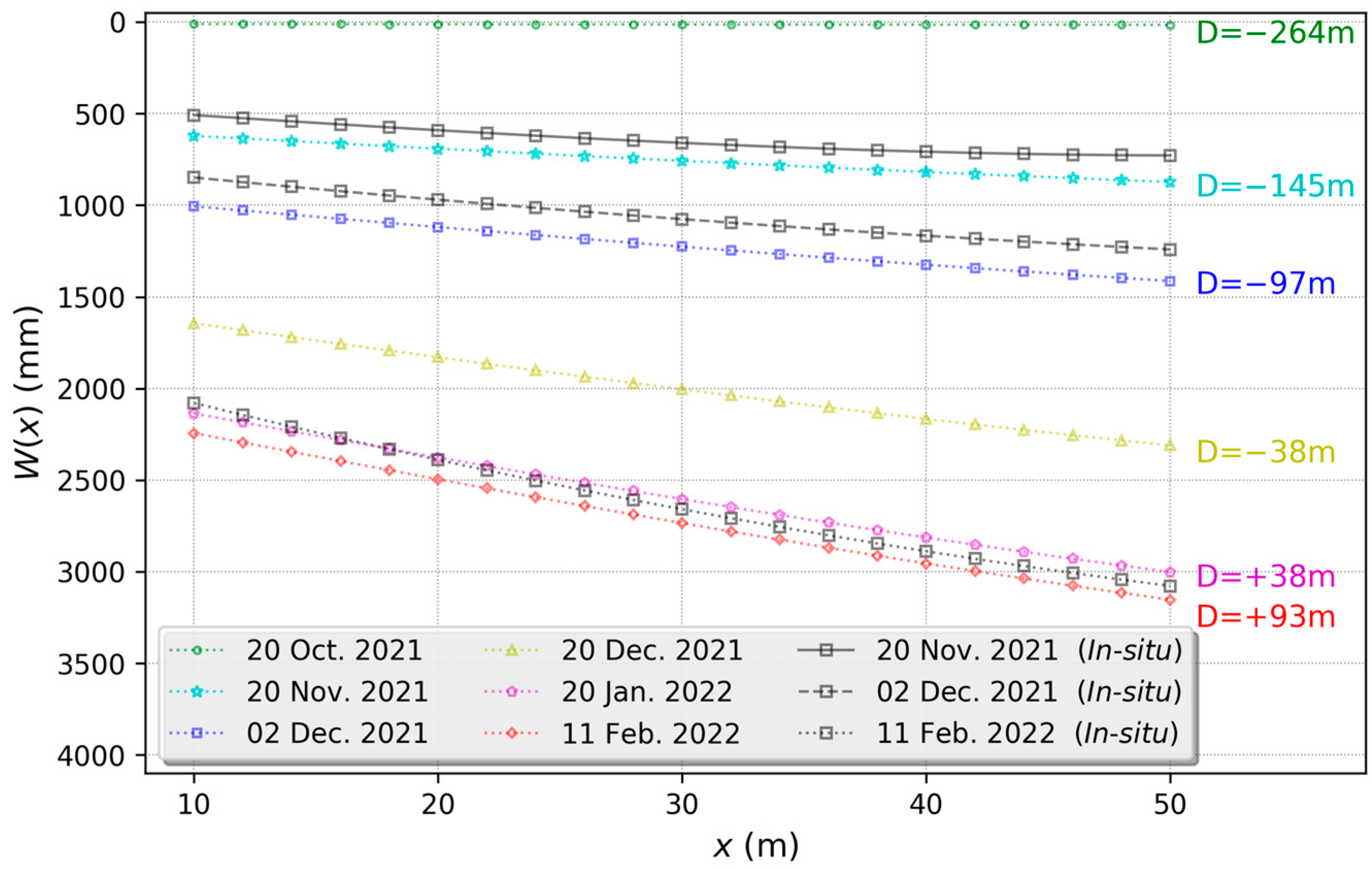
5.2. Spatial Characteristics of Ground Subsidence in the Study Area
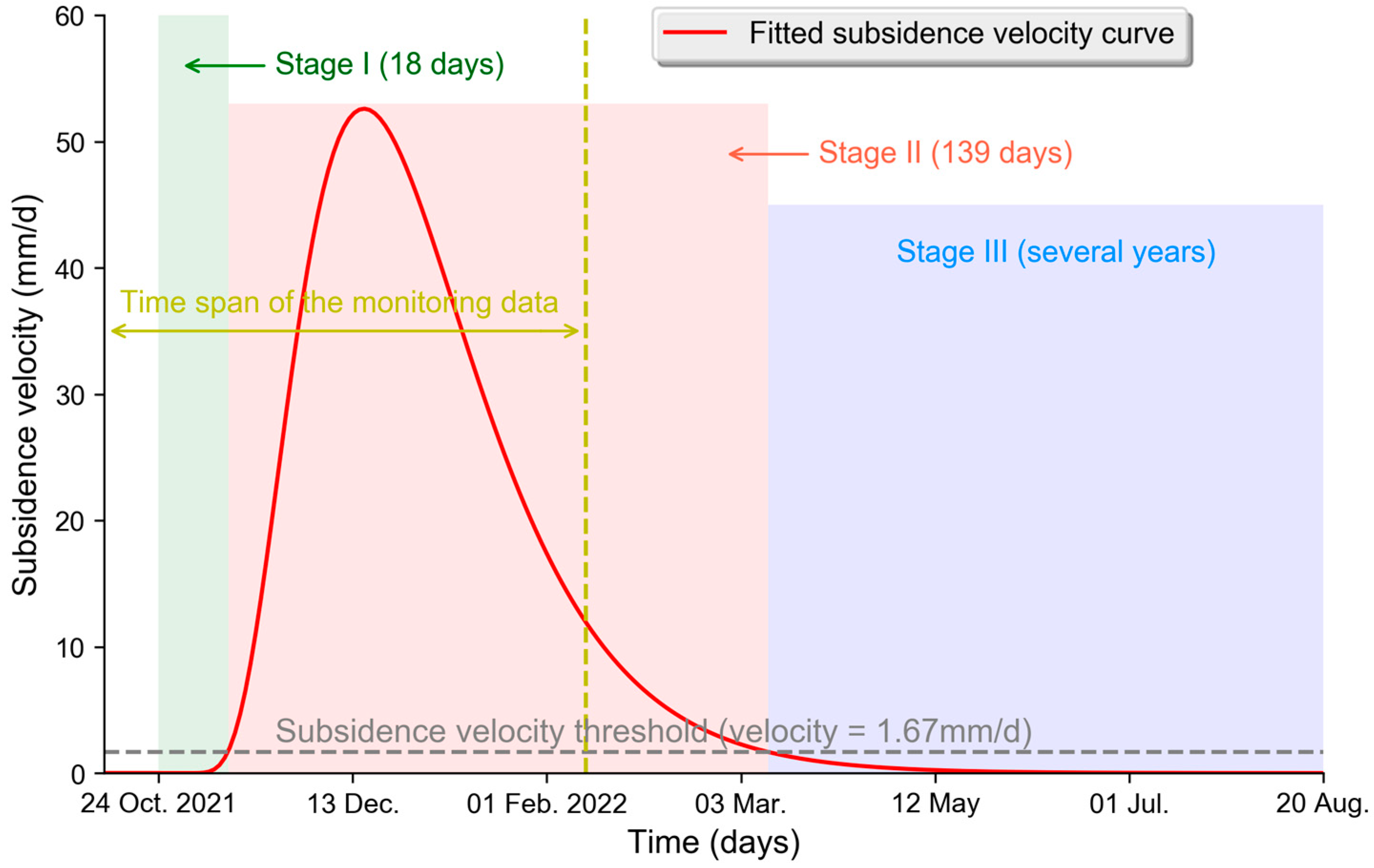
5.3. Temporal Characteristics of Ground Subsidence in the Study Area
5.4. Economic Cost and Efficiency Comparison
6. Conclusions
- (a)
- The maximum absolute error and the maximum relative error of the GNSS-IR-derived ground subsidence are 155.6 mm and 5.5% respectively, when the maximum ground subsidence induced by underground coal mining is 3076 mm. The SNR phase estimation error and the error of model describing ground subsidence pattern are the main reasons causing the GNSS-IR subsidence estimating error;
- (b)
- The influence distance of underground coal mining operation in the study area is about 145 m; and duration of the initial stage and the active stage is 18 and 139 days, respectively. The spatial and temporal characteristics of ground subsidence in the study area are compatible with the general pattern of subsidence caused by the underground caving mining; and
- (c)
- Economic cost of the proposed GNSS-IR subsidence monitoring technique is about a thirtieth of the GNSS-RTK technique, and is about fiftieth of the levelling subsidence monitoring method. Efficiency of the GNSS-IR method is also far better than the traditional GNSS-RTK and levelling method for monitoring ground subsidence induced by underground coal mining.
Author Contributions
Funding
Data Availability Statement
Acknowledgments
Conflicts of Interest
References
- Zhang, C.; Zhong, L.; Fu, X.; Zhao, Z. Managing Scarce Water Resources in China’s Coal Power Industry. Environ. Manag. 2016, 57, 1188–1203. [Google Scholar] [CrossRef] [PubMed]
- Bell, F.G.; Stacey, T.R.; Genske, D.D. Mining subsidence and its effect on the environment: Some differing examples. Environ. Geol. 2000, 40, 135–152. [Google Scholar] [CrossRef]
- Kay, D.J. Managing mine subsidence along railways and highway pavements in the southern coalfield. J. News Aust. Geomech. Soc. 2012, 47, 33–52. [Google Scholar]
- Bian, H.; Zhang, S.; Zhang, Q.; Zheng, N. Monitoring large-area mining subsidence by GNSS based on IGS stations. Trans. Nonferrous Met. Soc. China 2014, 24, 514–519. [Google Scholar] [CrossRef]
- Yu, K.; Li, Y.; Chang, X. Snow Depth Estimation Based on Combination of Pesudorange and Carrier Phase of GNSS Dual-Frequency Signals. IEEE Trans. Geosci. Remote Sens. 2019, 57, 1817–1828. [Google Scholar] [CrossRef]
- Larson, K.M. GPS interferometric reflectometry: Applications to surface soil moisture, snow depth, and vegetation water content in the western United States. Wiley Interdiscip. Rev. Water 2016, 3, 775–787. [Google Scholar] [CrossRef]
- Rodriguez-Alvarez, N.; Bosch-Lluis, X.; Camps, A.; Aguasca, A.; Vall-Llossera, M.; Valencia, E. Review of crop growth and soil moisture monitoring from a ground-based instrument implementing the interference pattern gnss-r technique. Radio Sci. 2016, 46, 1–11. [Google Scholar] [CrossRef]
- Li, Y.; Yu, K.; Chang, X.; Jin, T.; Li, J. Estimation of Wheat Height with SNR Observations Collected by Low-Cost Navigational GNSS Chip and RHCP Antenna. IEEE Geosci. Remote Sens. Lett. 2022, 19, 1–5. [Google Scholar]
- Rodriguez-Alvarez, N.; Marchan-Hernández, J.F.; Camps, A.; Bosch-Lluis, X.; Valencia, E.; Ramos-Pérez, I.; Vall-Llossera, M.; Monerris, A.; Martínez-Fernández, J.; Perez-Gmerrez, C.; et al. Topographic profile retrieval using the interference pattern GNSS-R technique. Proc. IEEE Int. Geosci. Remote Sens. Symp. 2009, 3, 420–423. [Google Scholar]
- Wang, X.; He, X.; Zhang, Q.; Niu, Z. The Preliminary Discussion of the Potential of GNSS-IR Technology for Terrain Retrievals. J. Geod. Geoinf. Sci. 2021, 4, 79–88. [Google Scholar]
- Hollenstein, C.; Müller, M.D.; Geiger, A.; Kahle, H.G. Crustal motion and deformation in Greece from a decade of GPS measurements, 1993–2003. Tectonophysics 2008, 449, 17–40. [Google Scholar] [CrossRef]
- Lazos, I.; Chatzipetros, A.; Pavlides, S.; Pikridas, C.; Bitharis, S. Tectonic crustal deformation of Corinth gulf, Greece, based on primary geodetic data. Acta Geodyn. Geomater. 2020, 17, 413–424. [Google Scholar] [CrossRef]
- Mcclusky, S.; Balassanian, S.; Barka, A.; Demir, C.; Ergintav, S.; Georgiev, I.; Gurkan, O.; Hamburger, M.; Hurst, K.; Kahle, H.; et al. Global Positioning System constraints on plate kinematics and dynamics in the eastern Mediterranean and Caucasus. J. Geophys. Res. 2000, 105, 5695–5719. [Google Scholar] [CrossRef]
- Müller, M.D.; Geiger, A.; Kahle, H.G.; Veis, G.; Billiris, H.; Paradissis, D.; Felekis, S. Velocity and deformation fields in the North Aegean domain, Greece, and implications for fault kinematics, derived from GPS data 1993–2009. Tectonophysics 2013, 597–598, 34–49. [Google Scholar] [CrossRef]
- Nyst, M.; Thatcher, W. New constraints on the active tectonic deformation of the Aegean. J. Geophys. Res. B Solid Earth 2004, 109, 1–23. [Google Scholar] [CrossRef] [Green Version]
- Reilinger, R.; McClusky, S.; Paradissis, D.; Ergintav, S.; Vernant, P. Geodetic constraints on the tectonic evolution of the Aegean region and strain accumulation along the Hellenic subduction zone. Tectonophysics 2010, 488, 22–30. [Google Scholar] [CrossRef]
- Gu, G. Advantages of GNSS in Monitoring Crustal Deformation for Detection of Precursors to Strong Earthquakes. Positioning 2013, 4, 11–19. [Google Scholar] [CrossRef] [Green Version]
- Unlu, T.; Akcin, H.; Yilmaz, O. An integrated approach for the prediction of subsidence for coal mining basins. Eng. Geol. 2013, 166, 186–203. [Google Scholar] [CrossRef]
- Li, L.; Wu, K.; Zhou, D. AutoCAD-based prediction of 3D dynamic ground movement for underground coal mining. Int. J. Rock Mech. Min. Sci. 2014, 71, 194–203. [Google Scholar] [CrossRef]
- Tan, X.; Song, B.; Bo, H.; Li, Y.; Wang, M.; Lu, G. Extraction of Irregularly Shaped Coal Mining Area Induced Ground Subsidence Prediction Based on Probability Integral Method. Appl. Sci. 2020, 10, 6623. [Google Scholar] [CrossRef]
- Larson, K.M.; Small, E.E.; Gutmann, E.; Bilich, A.; Axelrad, P.; Braun, J. Using GPS multipath to measure soil moisture fluctuations: Initial results. GPS Solut. 2008, 12, 173–177. [Google Scholar] [CrossRef]
- Hofmann-Wellenhof, B.; Lichtenegger, H.; Wasle, E. GNSS-Global Navigation Satellite System: GPS, GlONASS, Galileo and More; Springer: New York, NY, USA, 2008. [Google Scholar]
- Li, Y.; Yu, K.; Jin, T.; Chang, X.; Wang, Q.; Li, J. Development of a GNSS-IR instrument based on low-cost positioning chips and its performance evaluation for estimating the reflector height. GPS Solut. 2021, 25, 127. [Google Scholar] [CrossRef]
- Larson, K.M.; Small, E.E.; Gutmann, E.D.; Bilich, A.L.; Braun, J.J.; Zavorotny, V.U. Use of GPS receivers as a soil moisture network for water cycle studies. Geophys. Res. Lett. 2008, 35, 1–4. [Google Scholar] [CrossRef] [Green Version]
- Li, Y.; Yu, K.; Jin, T.; Chang, X.; Zhang, Q.; Yang, S. Measuring Soil Moisture with Refracted GPS Signals. IEEE Geosci. Remote Sens. Lett. 2022, 19, 1–5. [Google Scholar] [CrossRef]
- Donnelly, L.J.; Cruz, D.; Asmar, I.; Zapata, O.; Perez, J.D. The monitoring and prediction of mining subsidence in the Amaga, Angelopolis, Venecia and Bolombolo Regions, Antioquia, Colombia. Eng. Geol. 2001, 59, 103–114. [Google Scholar] [CrossRef]
- Alien, A.S. Basic questions concerning coal mine subsidence in the United States: Association of Engineering. Geol. Bull. 1978, 15, 147–161. [Google Scholar]
- Whetton, J.T.; King, H.J. The Time Factor in Mining Subsidence; Clark, G.B., Ed.; International Symposium on Mining Research: Rolla, MO, USA, 1961; Volume 2, pp. 521–539. [Google Scholar]
- Zhao, Y.; Hu, Z. Proper time model for pre-reclamation of unstable subsidence. J. China Coal Soc. 2008, 33, 157–161. [Google Scholar]
- Li, H.; Zha, J.; Guo, G. A new dynamic prediction method for surface subsidence based on numerical model parameter sensitivity. J. Clean. Prod. 2019, 233, 1418–1424. [Google Scholar] [CrossRef]
- Han, J.; Hu, C.; Zou, J. Time Function Model of Surface Subsidence Based on Inversion Analysis in Deep Soil Strata. Math. Probl. Eng. 2020, 2, 1–6. [Google Scholar] [CrossRef]


| Date | Mean (mm) | STD (mm) | RMSE (mm) | Maximum RE (%) |
|---|---|---|---|---|
| 20 November 2021 | 109.3 | 13.1 | 110.1 | 4.7 |
| 02 December 2021 | 155.4 | 7.0 | 155.6 | 5.5 |
| 11 February 2022 | 91.5 | 29.4 | 96.2 | 5.3 |
| Method | Point Count | Monitoring Period (Days) | Unit Price (Dollars per Point) | Total Price (Dollars) |
|---|---|---|---|---|
| GNSS-IR | 20 | 730 | - | 1140 |
| GNSS-RTK | 20 | 730 | 2.1 | 32,186 |
| Levelling | 20 | 730 | 3.6 | 52,143 |
| Method | Point Count | Monitoring Period (Days) | Unit Time (Minutes per Point) | Total Time (Minutes) |
|---|---|---|---|---|
| GNSS-IR | 20 | 730 | Near-real time | Near-real time |
| GNSS-RTK | 20 | 730 | 2 (Manual) | 30,400 |
| Levelling | 20 | 730 | 5 (Manual) | 76,000 |
Disclaimer/Publisher’s Note: The statements, opinions and data contained in all publications are solely those of the individual author(s) and contributor(s) and not of MDPI and/or the editor(s). MDPI and/or the editor(s) disclaim responsibility for any injury to people or property resulting from any ideas, methods, instructions or products referred to in the content. |
© 2022 by the authors. Licensee MDPI, Basel, Switzerland. This article is an open access article distributed under the terms and conditions of the Creative Commons Attribution (CC BY) license (https://creativecommons.org/licenses/by/4.0/).
Share and Cite
Bo, H.; Li, Y.; Tan, X.; Dong, Z.; Zheng, G.; Wang, Q.; Yu, K. Estimation of Ground Subsidence Deformation Induced by Underground Coal Mining with GNSS-IR. Remote Sens. 2023, 15, 96. https://doi.org/10.3390/rs15010096
Bo H, Li Y, Tan X, Dong Z, Zheng G, Wang Q, Yu K. Estimation of Ground Subsidence Deformation Induced by Underground Coal Mining with GNSS-IR. Remote Sensing. 2023; 15(1):96. https://doi.org/10.3390/rs15010096
Chicago/Turabian StyleBo, Huaizhi, Yunwei Li, Xianfeng Tan, Zhoubin Dong, Guodong Zheng, Qi Wang, and Kegen Yu. 2023. "Estimation of Ground Subsidence Deformation Induced by Underground Coal Mining with GNSS-IR" Remote Sensing 15, no. 1: 96. https://doi.org/10.3390/rs15010096