

Estimation of Vertical Phase Center Offset and Phase Center Variations for BDS-3 B1CB2a Signals

Abstract
:1. Introduction
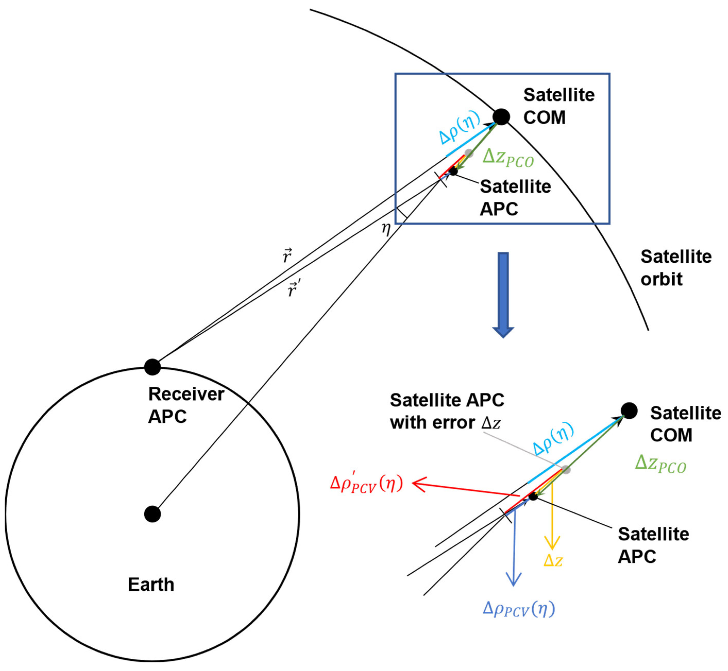
2. PCC Model
2.1. Basic Model
2.2. Estimation Methods
3. Processing Strategy
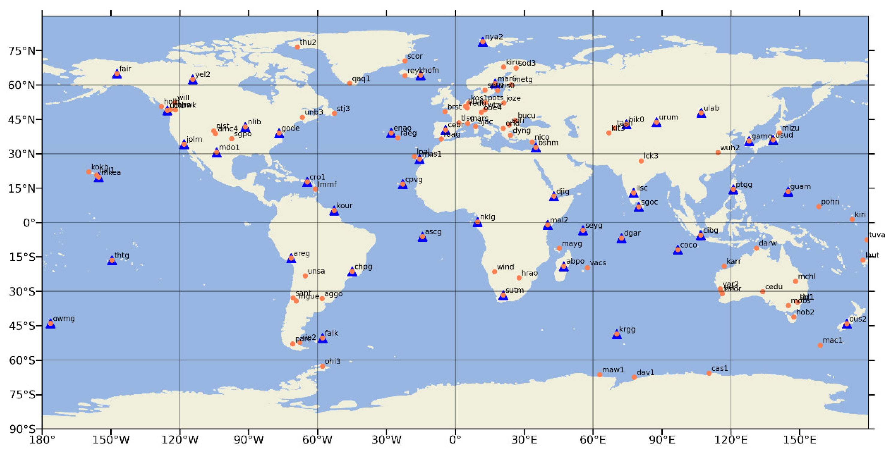
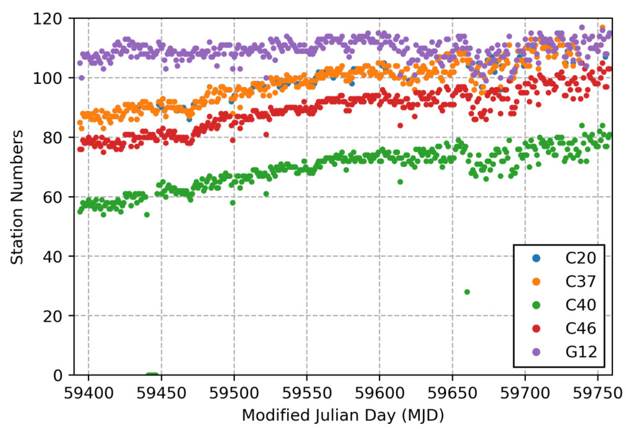
3.1. Data Availability
3.2. Basic POD Models and Strategies
4. Results of PCO-Z and PCVs
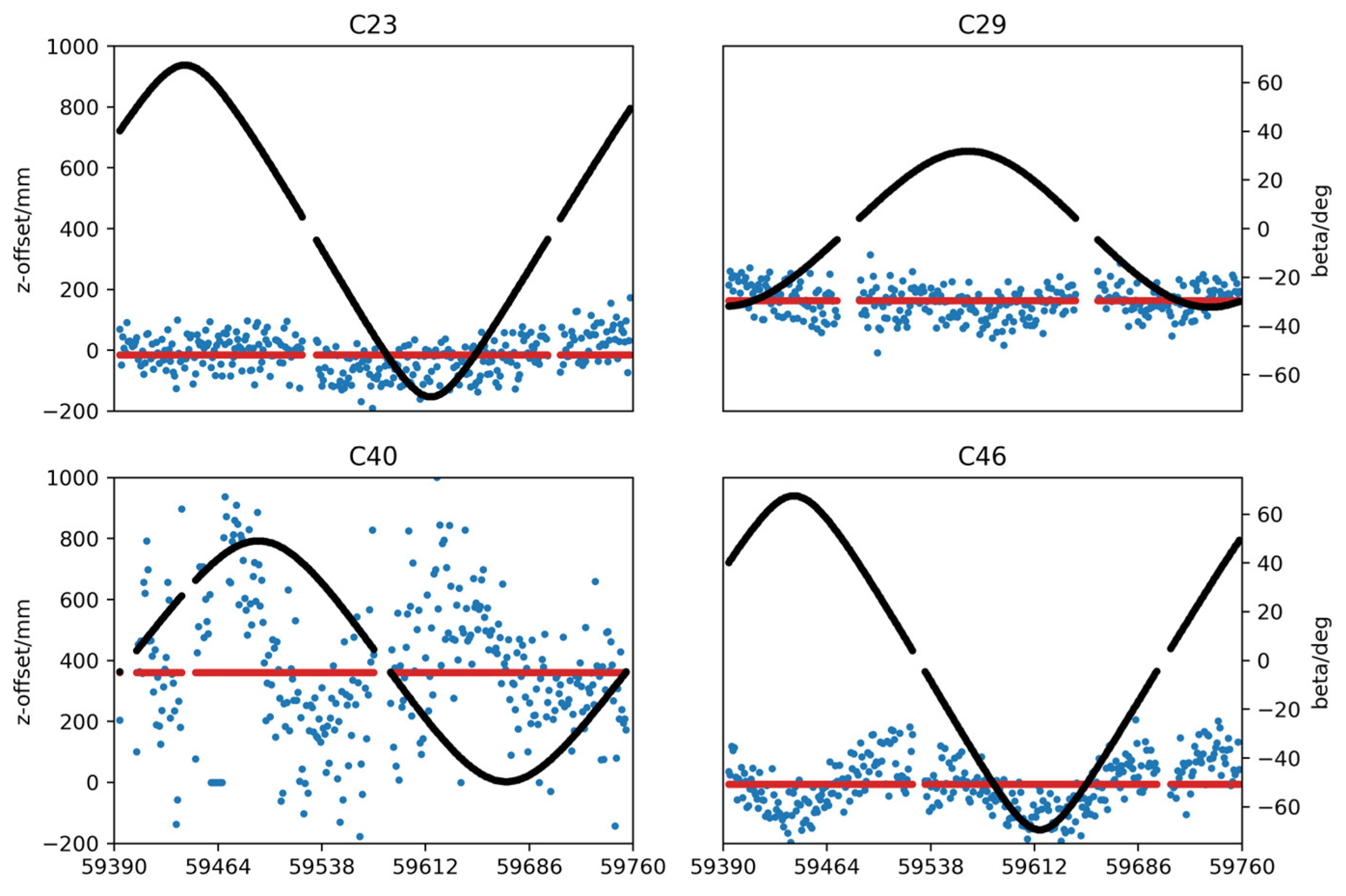
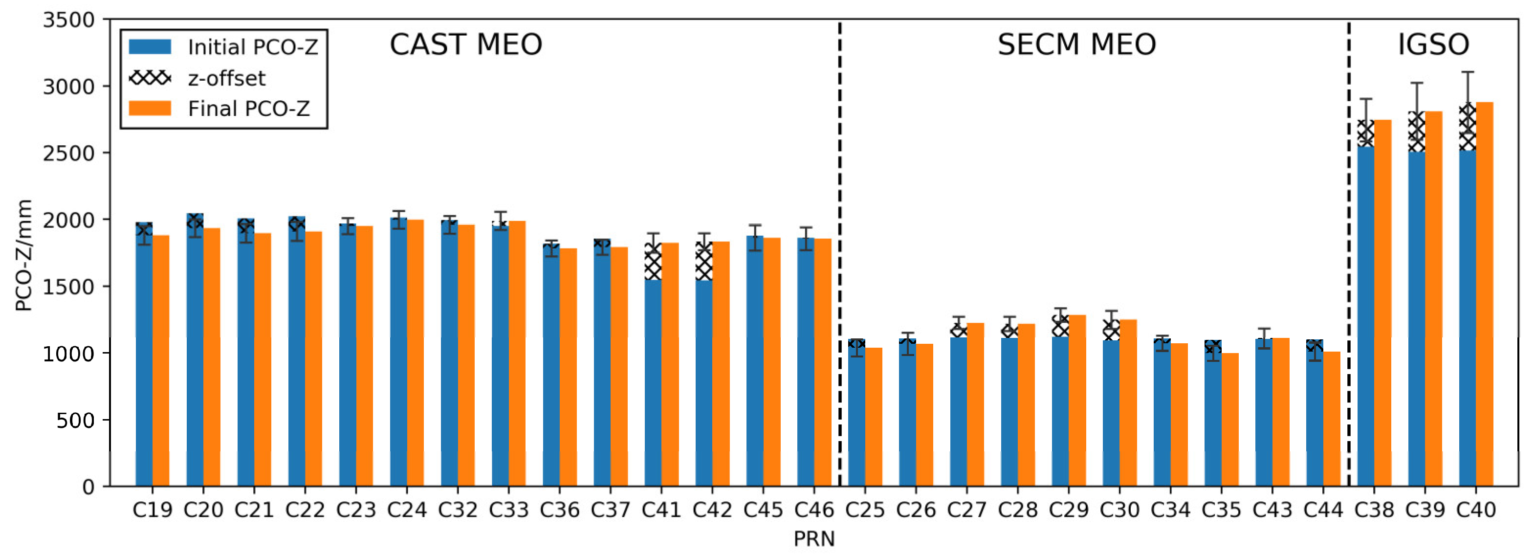
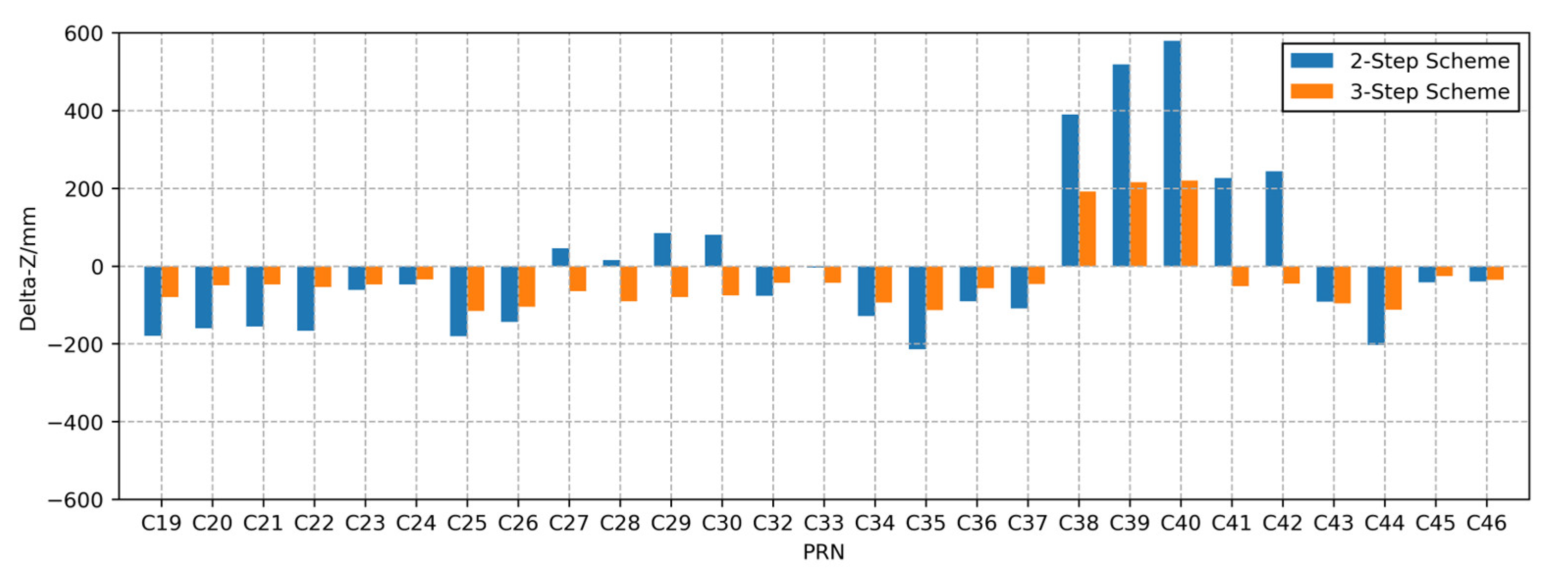
4.1. PCO-Z Parameters of the 3-Step Scheme
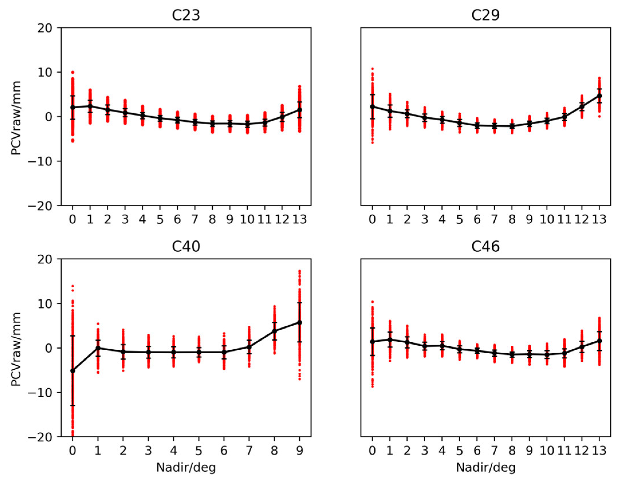
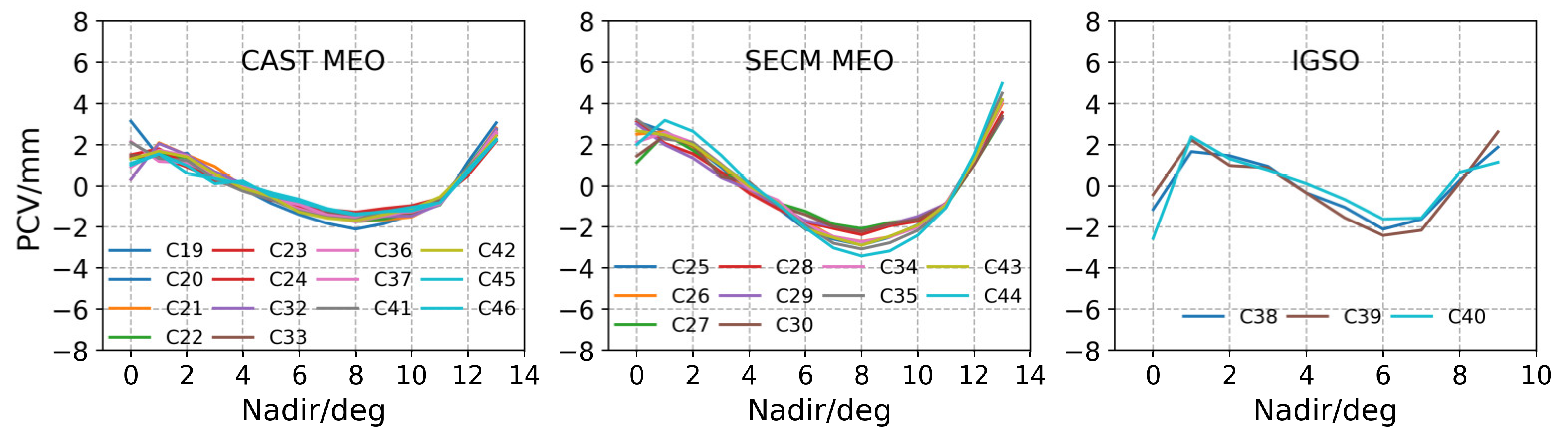
4.2. PCO-Z and PCVs
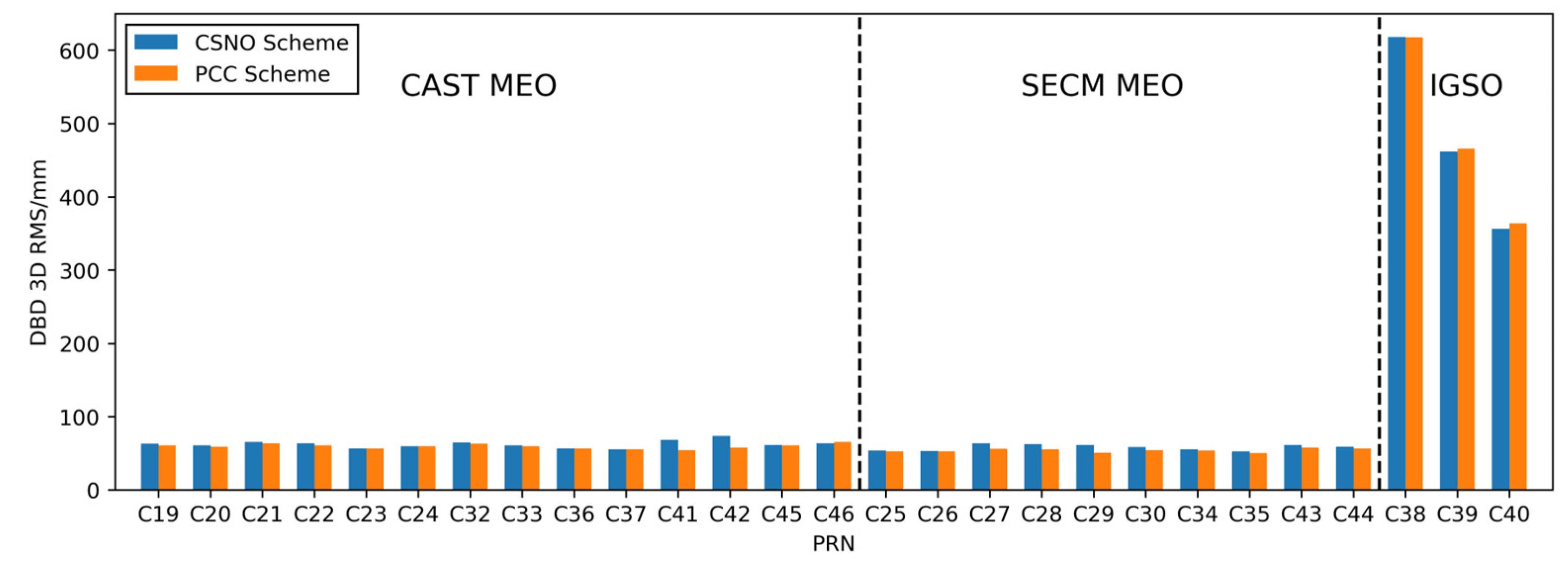
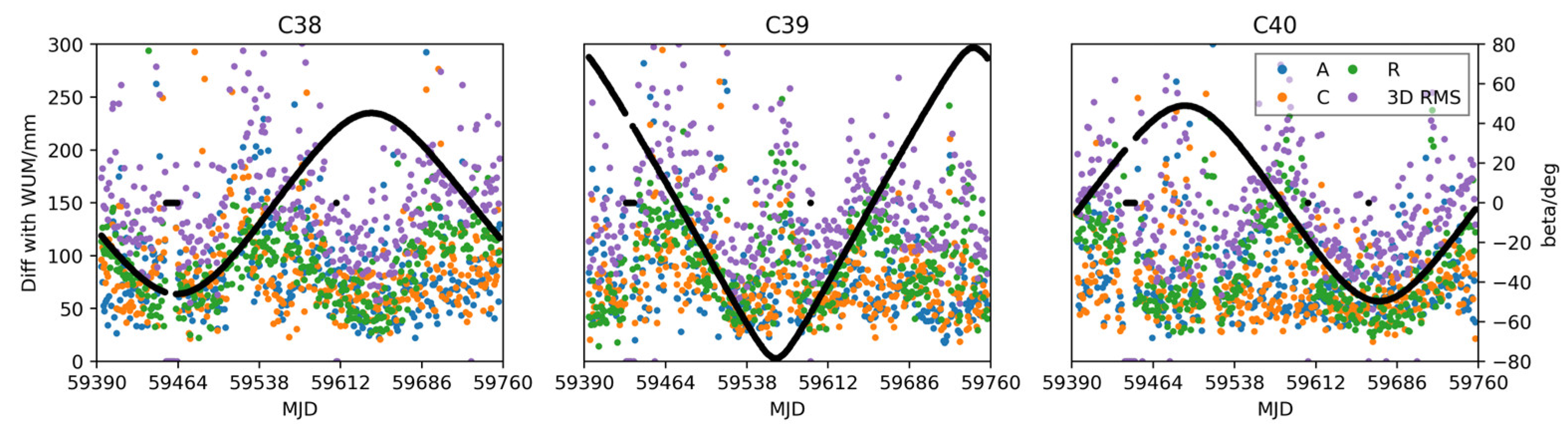
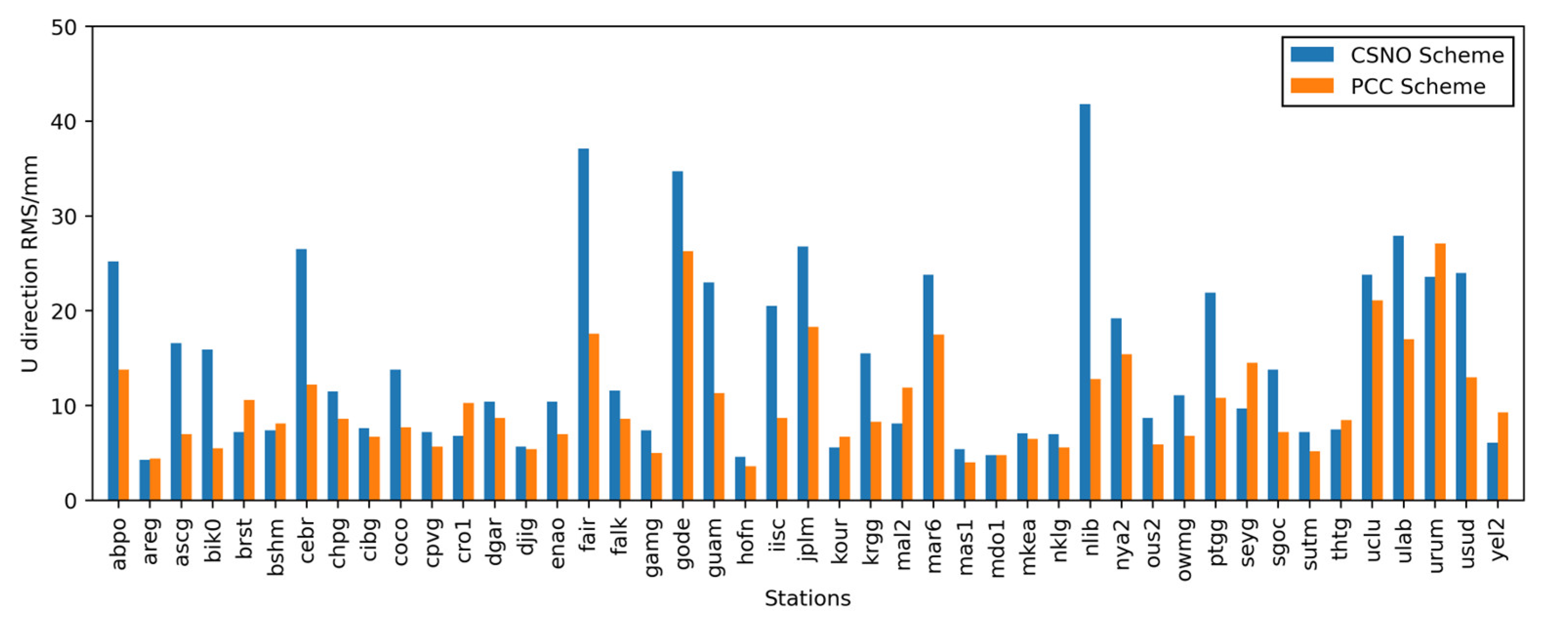
5. Validations
6. Summary and Discussions
Author Contributions
Funding
Data Availability Statement
Acknowledgments
Conflicts of Interest
References
- Yang, Y.; Liu, L.; Li, J.; Yang, Y.; Zhang, T.; Mao, Y.; Sun, B.; Ren, X. Featured services and performance of BDS-3. Sci. Bull. 2021, 66, 2135–2143. [Google Scholar] [CrossRef]
- Ye, F.; Yuan, Y.; Yang, Z. Validation and evaluation on B1IB3I-based and B1CB2a-based BDS-3 precise orbits from iGMAS. Adv. Space Res. 2022, 70, 2167–2177. [Google Scholar] [CrossRef]
- Yang, Y.; Gao, W.; Guo, S.; Mao, Y.; Yang, Y. Introduction to BeiDou-3 navigation satellite system. Navigation 2019, 66, 7–18. [Google Scholar] [CrossRef] [Green Version]
- Lu, J.; Guo, X.; Su, C. Global capabilities of BeiDou Navigation Satellite System. Satell. Navig. 2020, 1, 16. [Google Scholar] [CrossRef]
- Li, R.; Wang, N.; Li, Z.; Zhang, Y.; Wang, Z.; Ma, H. Precise orbit determination of BDS-3 satellites using B1C and B2a dual-frequency measurements. GPS Solut. 2021, 25, 95. [Google Scholar] [CrossRef]
- Schmid, R.; Steigenberger, P.; Gendt, G.; Ge, M.; Rothacher, M. Generation of a consistent absolute phase-center correction model for GPS receiver and satellite antennas. J. Geod. 2007, 81, 781–798. [Google Scholar] [CrossRef] [Green Version]
- Zhang, X.; Wu, M.; Liu, W.; Li, X.; Yu, S.; Lu, C.; Wickert, J. Initial assessment of the COMPASS/BeiDou-3: New-generation navigation signals. J. Geod. 2017, 91, 1225–1240. [Google Scholar] [CrossRef]
- Yan, X.; Huang, G.; Zhang, Q.; Liu, C.; Wang, L.; Qin, Z. Early analysis of precise orbit and clock offset determination for the satellites of the global BeiDou-3 system. Adv. Space Res. 2019, 63, 1270–1279. [Google Scholar] [CrossRef]
- Zhang, Y.; Kubo, N.; Chen, J.; Wang, J.; Wang, H. Initial Positioning Assessment of BDS New Satellites and New Signals. Remote Sens. 2019, 11, 1320. [Google Scholar] [CrossRef] [Green Version]
- Schmid, R.; Dach, R.; Collilieux, X.; Jäggi, A.; Schmitz, M.; Dilssner, F. Absolute IGS antenna phase center model igs08.atx: Status and potential improvements. J. Geod. 2015, 90, 343–364. [Google Scholar] [CrossRef]
- BeiDou Navigation Satellite System. Satellite Antenna Phase Center of BDS. Available online: http://en.beidou.gov.cn/SYSTEMS/Officialdocument/201912/P020200103555670269778.atx (accessed on 7 November 2022).
- Dilssner, F.; Springer, T.; Schönemann, E.; Enderle, W. Estimation of satellite antenna phase center corrections for BeiDou. In Proceedings of the IGS Workshop, Pasadena, CA, USA, 23–27 June 2014; pp. 23–27. [Google Scholar]
- Guo, J.; Xu, X.; Zhao, Q.; Liu, J. Precise orbit determination for quad-constellation satellites at Wuhan University: Strategy, result validation, and comparison. J. Geod. 2015, 90, 143–159. [Google Scholar] [CrossRef]
- Huang, G.; Yan, X.; Zhang, Q.; Liu, C.; Wang, L.; Qin, Z. Estimation of antenna phase center offset for BDS IGSO and MEO satellites. GPS Solut. 2018, 22, 49. [Google Scholar] [CrossRef]
- Yan, X.; Huang, G.; Zhang, Q.; Wang, L.; Qin, Z.; Xie, S. Estimation of the Antenna Phase Center Correction Model for the BeiDou-3 MEO Satellites. Remote Sens. 2019, 11, 2850. [Google Scholar] [CrossRef] [Green Version]
- Xia, F.; Ye, S.; Chen, D.; Wu, J.; Wang, C.; Sun, W. Estimation of antenna phase center offsets for BeiDou IGSO and MEO satellites. GPS Solut. 2020, 24, 90. [Google Scholar] [CrossRef]
- Qu, Z.; Guo, J.; Zhao, Q. Phase Center Corrections for BDS IGSO and MEO Satellites in IGb14 and IGSR3 Frame. Remote Sens. 2021, 13, 745. [Google Scholar] [CrossRef]
- Zajdel, R.; Steigenberger, P.; Montenbruck, O. On the potential contribution of BeiDou-3 to the realization of the terrestrial reference frame scale. GPS Solut. 2022, 26, 109. [Google Scholar] [CrossRef]
- Montenbruck, O.; Schmid, R.; Mercier, F.; Steigenberger, P.; Noll, C.; Fatkulin, R.; Kogure, S.; Ganeshan, A.S. GNSS satellite geometry and attitude models. Adv. Space Res. 2015, 56, 1015–1029. [Google Scholar] [CrossRef] [Green Version]
- Steigenberger, P.; Fritsche, M.; Dach, R.; Schmid, R.; Montenbruck, O.; Uhlemann, M.; Prange, L. Estimation of satellite antenna phase center offsets for Galileo. J. Geod. 2016, 90, 773–785. [Google Scholar] [CrossRef]
- Zhu, S.Y.; Massmann, F.H.; Yu, Y.; Reigber, C. Satellite antenna phase center offsets and scale errors in GPS solutions. J. Geod. 2003, 76, 668–672. [Google Scholar] [CrossRef]
- Ge, M. Impact of GPS satellite antenna offsets on scale changes in global network solutions. Geophys. Res. Lett. 2005, 32, L06310. [Google Scholar] [CrossRef]
- Schmid, R.; Rothacher, M. Estimation of elevation-dependent satellite antenna phase center variations of GPS satellites. J. Geod. 2003, 77, 440–446. [Google Scholar] [CrossRef] [Green Version]
- Xie, S.; Huang, G.; Wang, L.; Yan, X.; Qin, Z.; Cao, Y. A Refinement of Antenna Phase Center Correction Model for BDS IGSO and MEO Satellites. J. Geod. 2022; submitted. [Google Scholar]
- Chen, J.; Wang, J.; Yu, C.; Zhang, Y.; Wang, B. Improving BDS broadcast ephemeris accuracy using ground-satellite-link observations. Satell. Navig. 2022, 3, 11. [Google Scholar] [CrossRef]
- Montenbruck, O.; Steigenberger, P.; Hugentobler, U. Enhanced solar radiation pressure modeling for Galileo satellites. J. Geod. 2014, 89, 283–297. [Google Scholar] [CrossRef]
- Beutler, G.; Brockmann, E.; Gurtner, W.; Hugentobler, U.; Mervart, L.; Rothacher, M.; Verdun, A. Extended orbit modeling techniques at the CODE processing center of the international GPS service for geodynamics (IGS): Theory and initial results. manuscripta geodaetica. 1994, 19, 367–386. [Google Scholar]
- Springer, T.A.; Beutler, G.; Rothacher, M. A New Solar Radiation Pressure Model for GPS Satellites. GPS Solut. 1999, 2, 50–62. [Google Scholar] [CrossRef]
- Arnold, D.; Meindl, M.; Beutler, G.; Dach, R.; Schaer, S.; Lutz, S.; Prange, L.; Sośnica, K.; Mervart, L.; Jäggi, A. CODE’s new solar radiation pressure model for GNSS orbit determination. J. Geod. 2015, 89, 775–791. [Google Scholar] [CrossRef] [Green Version]
- Li, X.; Yuan, Y.; Zhu, Y.; Jiao, W.; Bian, L.; Li, X.; Zhang, K. Improving BDS-3 precise orbit determination for medium earth orbit satellites. GPS Solut. 2020, 24, 53. [Google Scholar] [CrossRef]
- BeiDou Navigation Satellite System. Satellite Information of BDS. Available online: http://en.beidou.gov.cn/SYSTEMS/Officialdocument/201912/P020200103556125703019.rar (accessed on 7 November 2022).
- Zhao, Q.; Guo, J.; Wang, C.; Lyu, Y.; Xu, X.; Yang, C.; Li, J. Precise orbit determination for BDS satellites. Satell. Navig. 2022, 3, 2. [Google Scholar] [CrossRef]
- Solano, C.J.R. Impact of Albedo modelling in GPS orbits. 2009. [Google Scholar]
- Steigenberger, P.; Thoelert, S.; Montenbruck, O. GNSS satellite transmit power and its impact on orbit determination. J. Geod. 2017, 92, 609–624. [Google Scholar] [CrossRef]
- Steigenberger, P.T.S. Initial BDS-3 transmit power analysis (with BDS-2 gain pattern). 2020. [Google Scholar]
- Saastamoinen, J. Contributions to the theory of atmospheric refraction. Bull. Géodésique 2008, 105, 279–298. [Google Scholar] [CrossRef]
- Boehm, J.; Niell, A.; Tregoning, P.; Schuh, H. Global Mapping Function (GMF): A new empirical mapping function based on numerical weather model data. Geophys. Res. Lett. 2006, 33, L07304. [Google Scholar] [CrossRef]
- Ge, M.; Gendt, G.; Dick, G.; Zhang, F.P. Improving carrier-phase ambiguity resolution in global GPS network solutions. J. Geod. 2005, 79, 103–110. [Google Scholar] [CrossRef]
- Griffiths, J.; Ray, J.R. On the precision and accuracy of IGS orbits. J. Geod. 2009, 83, 277–287. [Google Scholar] [CrossRef]


| Items | Description |
|---|---|
| Number of stations | ≈120 MGEX stations |
| Time interval | DOY 180, 2021 to DOY 179, 2022 |
| Observation | Zero-difference phase and code observation for GPS L1/L2 and BDS-3 B1C/B2a dual-frequency signals |
| Sampling rate | 300 s |
| Elevation cut-off angle | 7° |
| Arc length | 24-h |
| Ionosphere | Ionosphere-free linear combination |
| Troposphere | Saastamoinen model [36] used as a priori model; ZTDs at 2 h interval is estimated; horizontal gradients estimated at 6 h interval with Global Mapping Function (GMF) [37] |
| Ambiguity fixing | Double-difference ambiguity fix [38] |
| Stations coordinates | Fixed |
| Solar radiation model | GPS: ECOM1 BDS-3: ECOM1 + a priori box-wing model |
| Earth radiation model | Box-wing [33] |
| Antenna thrust | GPS: 50–300 W [34] BDS-3: 130–310 W [34,35] |
| Satellites PCOs | GPS: igs14_2223.atx BDS-3: CSNO published model as a priori model |
| Satellites PCVs | GPS: igs14_2223.atx BDS-3: Zero as initial value |
| Receiver PCC | GPS: igs14_2223.atx BDS-3: igsR3_2077.atx or using L1/L2 for B1C/B2a |
| PRN | z-Offset | RMSE | PCO-Z | PRN | z-Offset | RMSE | PCO-Z |
|---|---|---|---|---|---|---|---|
| C19 | −99.24 | 69.69 | 1880.48 | C34 | −34.94 | 57.18 | 1073.17 |
| C20 | −110.30 | 65.01 | 1935.26 | C35 | −100.47 | 57.46 | 997.82 |
| C21 | −108.91 | 69.06 | 1898.07 | C36 | −33.91 | 59.59 | 1782.81 |
| C22 | −111.87 | 71.19 | 1910.18 | C37 | −62.96 | 57.42 | 1792.05 |
| C23 | −14.92 | 60.02 | 1950.06 | C38 | 199.21 | 158.68 | 2744.77 |
| C24 | −13.08 | 66.54 | 1999.41 | C39 | 304.75 | 213.11 | 2810.12 |
| C25 | −65.01 | 63.31 | 1038.91 | C40 | 361.33 | 228.24 | 2877.62 |
| C26 | −39.24 | 82.28 | 1068.55 | C41 | 277.91 | 72.86 | 1823.20 |
| C27 | 110.54 | 45.05 | 1225.97 | C42 | 288.23 | 63.17 | 1832.81 |
| C28 | 105.66 | 52.72 | 1218.22 | C43 | 5.00 | 73.70 | 1110.45 |
| C29 | 164.27 | 50.81 | 1284.07 | C44 | −90.66 | 68.96 | 1011.32 |
| C30 | 154.95 | 68.52 | 1249.08 | C45 | −16.33 | 94.91 | 1862.69 |
| C32 | −33.27 | 66.74 | 1961.20 | C46 | −5.09 | 85.66 | 1856.54 |
| C33 | 39.50 | 67.84 | 1989.29 |
| PRN | 2-Step Scheme | 3-Step Scheme | Diff | PRN | 2-Step Scheme | 3-Step Scheme | Diff | ||||
|---|---|---|---|---|---|---|---|---|---|---|---|
| PCO-Z | PCO-Z | PCO-Z | PCO-Z | ||||||||
| C19 | −178.97 | 1800.75 | −79.66 | 1800.82 | −0.07 | C34 | −128.57 | 979.54 | −93.91 | 979.26 | 0.28 |
| C20 | −159.39 | 1886.17 | −49.16 | 1886.10 | 0.07 | C35 | −213.20 | 885.09 | −112.95 | 884.87 | 0.22 |
| C21 | −155.52 | 1851.47 | −46.73 | 1851.34 | 0.12 | C36 | −90.62 | 1726.10 | −56.64 | 1726.17 | −0.07 |
| C22 | −165.51 | 1856.54 | −53.77 | 1856.41 | 0.13 | C37 | −109.08 | 1745.93 | −46.06 | 1745.99 | −0.06 |
| C23 | −61.33 | 1903.65 | −46.52 | 1903.54 | 0.11 | C38 | 390.38 | 2935.94 | 191.87 | 2936.64 | −0.70 |
| C24 | −47.28 | 1965.21 | −34.13 | 1965.28 | −0.07 | C39 | 519.39 | 3024.76 | 215.76 | 3025.88 | −1.12 |
| C25 | −180.54 | 923.38 | −115.65 | 923.26 | 0.12 | C40 | 579.56 | 3095.85 | 220.47 | 3098.09 | −2.24 |
| C26 | −143.29 | 964.50 | −104 | 964.55 | −0.05 | C41 | 227.09 | 1772.39 | −51.39 | 1771.81 | 0.57 |
| C27 | 46.52 | 1161.95 | −63.79 | 1162.18 | −0.23 | C42 | 243.85 | 1788.42 | −45.07 | 1787.74 | 0.69 |
| C28 | 15.47 | 1128.03 | −89.76 | 1128.46 | −0.43 | C43 | −90.94 | 1014.51 | −95.99 | 1014.46 | 0.05 |
| C29 | 84.61 | 1204.42 | −79.67 | 1204.40 | 0.01 | C44 | −202.65 | 899.33 | −111.92 | 899.40 | −0.07 |
| C30 | 80.39 | 1174.52 | −74.71 | 1174.37 | 0.15 | C45 | −41.74 | 1837.29 | −25.66 | 1837.03 | 0.25 |
| C32 | −76.23 | 1918.25 | −43.06 | 1918.14 | 0.10 | C46 | −39.59 | 1822.04 | −34.54 | 1822.00 | 0.04 |
| C33 | −3.38 | 1946.41 | −42.91 | 1946.38 | 0.03 | ||||||
| PRN | Nadir-Angle/° | |||||||||||||
|---|---|---|---|---|---|---|---|---|---|---|---|---|---|---|
| 0° | 1° | 2° | 3° | 4° | 5° | 6° | 7° | 8° | 9° | 10° | 11° | 12° | 13° | |
| C19 | 3.12 | 1.44 | 1.23 | 0.43 | −0.13 | −0.84 | −1.39 | −1.83 | −2.11 | −1.84 | −1.41 | −0.91 | 1.18 | 3.07 |
| C20 | 1.39 | 1.47 | 1.59 | 0.15 | 0.18 | −0.52 | −0.95 | −1.43 | −1.7 | −1.44 | −1.38 | −0.84 | 0.75 | 2.75 |
| C21 | 0.33 | 2.10 | 1.50 | 0.94 | 0.00 | −0.3 | −0.98 | −1.53 | −1.74 | −1.67 | −1.51 | −0.82 | 0.86 | 2.81 |
| C22 | 1.32 | 1.53 | 1.38 | 0.64 | 0.02 | −0.41 | −1.05 | −1.47 | −1.75 | −1.62 | −1.35 | −0.92 | 0.97 | 2.72 |
| C23 | 1.52 | 1.82 | 1.04 | 0.42 | −0.16 | −0.69 | −0.99 | −1.35 | −1.52 | −1.35 | −1.30 | −0.74 | 0.74 | 2.56 |
| C24 | 1.45 | 1.43 | 0.91 | 0.30 | −0.17 | −0.52 | −1.01 | −1.14 | −1.28 | −1.10 | −0.96 | −0.59 | 0.52 | 2.16 |
| C25 | 3.14 | 2.65 | 1.97 | 0.90 | −0.23 | −1.07 | −2.12 | −2.61 | −2.89 | −2.51 | −1.90 | −0.87 | 1.39 | 4.15 |
| C26 | 2.52 | 2.64 | 1.87 | 1.02 | −0.30 | −0.85 | −1.74 | −2.49 | −2.71 | −2.49 | −1.93 | −0.91 | 1.38 | 3.98 |
| C27 | 1.11 | 2.54 | 1.74 | 0.66 | 0.05 | −0.82 | −1.24 | −1.87 | −2.08 | −1.79 | −1.61 | −0.98 | 1.03 | 3.27 |
| C28 | 3.13 | 2.08 | 1.57 | 0.68 | −0.35 | −1.11 | −1.75 | −2.08 | −2.38 | −1.95 | −1.72 | −0.84 | 1.15 | 3.57 |
| C29 | 3.01 | 2.00 | 1.35 | 0.42 | −0.15 | −0.95 | −1.70 | −1.98 | −2.22 | −1.87 | −1.49 | −0.87 | 1.16 | 3.29 |
| C30 | 1.45 | 2.45 | 1.96 | 0.47 | 0.21 | −0.96 | −1.40 | −1.98 | −2.23 | −1.85 | −1.63 | −0.90 | 1.02 | 3.39 |
| C32 | 0.33 | 2.06 | 1.52 | 0.68 | 0.13 | −0.44 | −0.88 | −1.43 | −1.68 | −1.48 | −1.47 | −0.89 | 0.76 | 2.78 |
| C33 | 1.49 | 1.42 | 1.12 | 0.55 | −0.09 | −0.55 | −1.14 | −1.31 | −1.48 | −1.27 | −1.16 | −0.66 | 0.61 | 2.47 |
| C34 | 2.13 | 2.61 | 2.11 | 1.08 | −0.12 | −0.69 | −1.87 | −2.47 | −2.74 | −2.51 | −2.02 | −0.86 | 1.24 | 4.11 |
| C35 | 3.24 | 2.29 | 2.12 | 1.04 | 0.03 | −0.92 | −1.92 | −2.80 | −3.09 | −2.78 | −2.17 | −1.07 | 1.50 | 4.52 |
| C36 | 2.16 | 1.19 | 1.12 | 0.50 | 0.05 | −0.65 | −1.12 | −1.53 | −1.75 | −1.46 | −1.20 | −0.87 | 0.92 | 2.63 |
| C37 | 0.90 | 1.75 | 1.46 | 0.40 | 0.12 | −0.64 | −0.9 | −1.41 | −1.57 | −1.34 | −1.26 | −0.81 | 0.76 | 2.54 |
| C38 | −1.14 | 1.67 | 1.47 | 0.95 | −0.34 | −1.05 | −2.11 | −1.63 | 0.29 | 1.89 | ||||
| C39 | −0.42 | 2.25 | 0.99 | 0.88 | −0.34 | −1.56 | −2.42 | −2.16 | 0.15 | 2.64 | ||||
| C40 | −2.56 | 2.40 | 1.33 | 0.77 | 0.12 | −0.65 | −1.63 | −1.58 | 0.65 | 1.17 | ||||
| C41 | 2.15 | 1.33 | 1.23 | 0.34 | −0.25 | −0.66 | −1.23 | −1.54 | −1.66 | −1.23 | −1.13 | −0.58 | 0.93 | 2.29 |
| C42 | 1.43 | 1.66 | 1.40 | 0.55 | −0.12 | −0.52 | −1.28 | −1.59 | −1.71 | −1.41 | −1.12 | −0.53 | 0.80 | 2.44 |
| C43 | 2.66 | 2.50 | 2.01 | 1.01 | 0.00 | −0.82 | −2.09 | −2.52 | −2.90 | −2.46 | −1.92 | −0.93 | 1.26 | 4.20 |
| C44 | 2.01 | 3.19 | 2.66 | 1.50 | 0.14 | −0.87 | −2.04 | −3.03 | −3.42 | −3.18 | −2.41 | −1.07 | 1.53 | 4.99 |
| C45 | 0.99 | 1.57 | 0.61 | 0.38 | 0.12 | −0.31 | −0.65 | −1.11 | −1.36 | −1.26 | −1.04 | −0.81 | 0.66 | 2.21 |
| C46 | 1.10 | 1.56 | 0.98 | 0.13 | 0.27 | −0.47 | −0.76 | −1.18 | −1.42 | −1.25 | −1.22 | −0.81 | 0.80 | 2.26 |
| PRN | Nadir-Angle/° | |||||||||||||
|---|---|---|---|---|---|---|---|---|---|---|---|---|---|---|
| 0° | 1° | 2° | 3° | 4° | 5° | 6° | 7° | 8° | 9° | 10° | 11° | 12° | 13° | |
| C19 | 3.15 | 1.42 | 1.22 | 0.42 | −0.14 | −0.84 | −1.40 | −1.83 | −2.11 | −1.84 | −1.41 | −0.91 | 1.19 | 3.07 |
| C20 | 1.38 | 1.47 | 1.60 | 0.15 | 0.17 | −0.52 | −0.95 | −1.43 | −1.70 | −1.45 | −1.38 | −0.83 | 0.75 | 2.74 |
| C21 | 0.33 | 2.10 | 1.50 | 0.94 | 0.00 | −0.30 | −0.98 | −1.53 | −1.74 | −1.67 | −1.51 | −0.82 | 0.86 | 2.82 |
| C22 | 1.31 | 1.53 | 1.38 | 0.64 | 0.02 | −0.40 | −1.05 | −1.47 | −1.75 | −1.62 | −1.35 | −0.92 | 0.97 | 2.71 |
| C23 | 1.52 | 1.81 | 1.04 | 0.42 | −0.16 | −0.69 | −0.99 | −1.35 | −1.52 | −1.35 | −1.30 | −0.74 | 0.74 | 2.56 |
| C24 | 1.44 | 1.44 | 0.91 | 0.30 | −0.17 | −0.52 | −1.01 | −1.14 | −1.28 | −1.10 | −0.96 | −0.59 | 0.52 | 2.16 |
| C25 | 3.14 | 2.65 | 1.97 | 0.90 | −0.24 | −1.07 | −2.11 | −2.60 | −2.89 | −2.51 | −1.90 | −0.87 | 1.39 | 4.15 |
| C26 | 2.52 | 2.64 | 1.87 | 1.02 | −0.29 | −0.85 | −1.74 | −2.49 | −2.71 | −2.49 | −1.93 | −0.91 | 1.38 | 3.98 |
| C27 | 1.13 | 2.52 | 1.74 | 0.66 | 0.05 | −0.82 | −1.24 | −1.87 | −2.08 | −1.79 | −1.62 | −0.98 | 1.03 | 3.27 |
| C28 | 3.14 | 2.08 | 1.56 | 0.68 | −0.35 | −1.11 | −1.75 | −2.08 | −2.38 | −1.95 | −1.72 | −0.84 | 1.15 | 3.57 |
| C29 | 3.01 | 2.00 | 1.35 | 0.42 | −0.15 | −0.95 | −1.70 | −1.97 | −2.22 | −1.87 | −1.49 | −0.87 | 1.16 | 3.29 |
| C30 | 1.45 | 2.45 | 1.96 | 0.47 | 0.21 | −0.96 | −1.40 | −1.98 | −2.23 | −1.85 | −1.63 | −0.90 | 1.02 | 3.39 |
| C32 | 0.33 | 2.06 | 1.51 | 0.68 | 0.13 | −0.44 | −0.88 | −1.43 | −1.67 | −1.49 | −1.47 | −0.89 | 0.77 | 2.78 |
| C33 | 1.49 | 1.42 | 1.12 | 0.55 | −0.09 | −0.55 | −1.14 | −1.30 | −1.48 | −1.27 | −1.16 | −0.66 | 0.61 | 2.46 |
| C34 | 2.13 | 2.60 | 2.11 | 1.07 | −0.13 | −0.68 | −1.87 | −2.47 | −2.73 | −2.50 | −2.02 | −0.86 | 1.24 | 4.10 |
| C35 | 3.24 | 2.28 | 2.12 | 1.05 | 0.03 | −0.92 | −1.92 | −2.80 | −3.08 | −2.78 | −2.17 | −1.06 | 1.50 | 4.51 |
| C36 | 2.16 | 1.19 | 1.12 | 0.50 | 0.05 | −0.65 | −1.11 | −1.52 | −1.75 | −1.47 | −1.20 | −0.87 | 0.92 | 2.63 |
| C37 | 0.90 | 1.75 | 1.46 | 0.41 | 0.12 | −0.64 | −0.91 | −1.41 | −1.57 | −1.34 | −1.26 | −0.81 | 0.76 | 2.54 |
| C38 | −1.15 | 1.67 | 1.47 | 0.95 | −0.34 | −1.04 | −2.11 | −1.63 | 0.29 | 1.89 | ||||
| C39 | −0.42 | 2.24 | 0.99 | 0.88 | −0.34 | −1.56 | −2.42 | −2.17 | 0.16 | 2.63 | ||||
| C40 | −2.56 | 2.40 | 1.31 | 0.76 | 0.13 | −0.66 | −1.62 | −1.57 | 0.66 | 1.15 | ||||
| C41 | 2.12 | 1.34 | 1.24 | 0.35 | −0.24 | −0.66 | −1.22 | −1.54 | −1.65 | −1.23 | −1.13 | −0.58 | 0.92 | 2.29 |
| C42 | 1.31 | 1.69 | 1.41 | 0.58 | −0.09 | −0.51 | −1.28 | −1.58 | −1.70 | −1.41 | −1.12 | −0.53 | 0.79 | 2.43 |
| C43 | 2.68 | 2.48 | 2.00 | 1.01 | 0.00 | −0.82 | −2.08 | −2.53 | −2.90 | −2.46 | −1.92 | −0.93 | 1.26 | 4.20 |
| C44 | 2.02 | 3.20 | 2.66 | 1.49 | 0.14 | −0.87 | −2.04 | −3.03 | −3.42 | −3.18 | −2.41 | −1.07 | 1.53 | 4.99 |
| C45 | 1.00 | 1.56 | 0.61 | 0.38 | 0.12 | −0.31 | −0.65 | −1.11 | −1.36 | −1.27 | −1.04 | −0.81 | 0.66 | 2.21 |
| C46 | 1.09 | 1.55 | 0.98 | 0.13 | 0.27 | −0.46 | −0.76 | −1.18 | −1.42 | −1.25 | −1.22 | −0.80 | 0.80 | 2.26 |
| Scheme | CAST MEO | SECM MEO | IGSO |
|---|---|---|---|
| CSNO | 62.7 | 58.3 | 478.9 |
| PCC | 59.7 | 54.2 | 482.6 |
| Improvement (%) | 4.8% | 7.0% | −0.8% |
| Scheme | N | E | U |
|---|---|---|---|
| CSNO | 5 | 8.1 | 14.8 |
| PCC | 3.5 | 5.9 | 10.2 |
| Improvement (%) | 30.0% | 27.2% | 31.1% |
Publisher’s Note: MDPI stays neutral with regard to jurisdictional claims in published maps and institutional affiliations. |
© 2022 by the authors. Licensee MDPI, Basel, Switzerland. This article is an open access article distributed under the terms and conditions of the Creative Commons Attribution (CC BY) license (https://creativecommons.org/licenses/by/4.0/).
Share and Cite
Xie, S.; Huang, G.; Wang, L.; Yan, X.; Qin, Z. Estimation of Vertical Phase Center Offset and Phase Center Variations for BDS-3 B1CB2a Signals. Remote Sens. 2022, 14, 6380. https://doi.org/10.3390/rs14246380
Xie S, Huang G, Wang L, Yan X, Qin Z. Estimation of Vertical Phase Center Offset and Phase Center Variations for BDS-3 B1CB2a Signals. Remote Sensing. 2022; 14(24):6380. https://doi.org/10.3390/rs14246380
Chicago/Turabian StyleXie, Shichao, Guanwen Huang, Le Wang, Xingyuan Yan, and Zhiwei Qin. 2022. "Estimation of Vertical Phase Center Offset and Phase Center Variations for BDS-3 B1CB2a Signals" Remote Sensing 14, no. 24: 6380. https://doi.org/10.3390/rs14246380