

Improving Vehicle Positioning Performance in Urban Environment with Tight Integration of Multi-GNSS PPP-RTK/INS


1
Institute of Surveying and Mapping, Information Engineering University, Zhengzhou 450001, China
2
Institute of Space Science, Shangdong University, Weihai 264209, China
3
School of Geodesy and Geomatics, Wuhan University, Wuhan 430079, China
*
Author to whom correspondence should be addressed.
Remote Sens. 2022, 14(21), 5489; https://doi.org/10.3390/rs14215489
Submission received: 9 October 2022
/
Revised: 29 October 2022
/
Accepted: 29 October 2022
/
Published: 31 October 2022
(This article belongs to the Special Issue Precision Orbit Determination of Satellites)
Abstract
:Global navigation satellite system (GNSS) signals are easily blocked by urban canyons, tree-lined roads, and overpasses in urban environments, making it impossible to ensure continuous and reliable positioning using only GNSS, even with the widely used precise point positioning and real-time kinematic (PPP-RTK). Since the inertial navigation system (INS) and GNSS are complementary, a tightly coupled PPP-RTK/INS model is developed to improve the positioning performance in these GNSS-challenged scenarios, in which the atmospheric corrections are used to achieve a rapid ambiguity resolution and the mechanization results from INS are utilized to assist GNSS preprocessing, re-fixing, and reconvergence. The experiment was conducted using three sets of vehicle-mounted data, and the performance of low-cost receiver and microelectromechanical system (MEMS) inertial measurement unit (IMU) was compared. The result shows that the positioning accuracy of PPP-RTK/INS can reach 2 cm in the horizontal component and 5 cm in the vertical component in the open environment. In the complex urban environment, continuous and reliable positioning can be ensured during GNSS short interruption, ambiguity can be instantaneously re-fixed with the assistance of INS, and decimeter-level positioning accuracy can be achieved. As a result, the horizontal positioning errors of more than 95% of the total epochs were within 20 cm. In addition, average positioning accuracy better than 15 cm and 30 cm in the horizontal and vertical components, respectively, can be obtained using the low-cost receiver and MEMS IMU. Compared with tactical IMU, the improvements in positioning accuracy and the ambiguity fixing rate using the geodetic receiver were more significant.
1. Introduction
With the rapid development of emerging technologies such as robots and autonomous driving, the demand for high-precision and high-reliability positioning is increasingly urgent. Highly accurate and reliable location information is the basis of unmanned equipment, system control, and operation, which can promote the rapid development of the spatio-temporal information empowerment industry [1]. As an important infrastructure, the global navigation satellite system (GNSS) can provide all-weather global positioning, navigation, and timing (PNT) services, which have been widely used in various aspects of military and civilian fields.
Currently, there are two common positioning techniques in GNSS, one is real-time kinematic (RTK) and the other is precise point positioning (PPP). RTK can achieve real-time centimeter-level positioning by fixing double-difference ambiguity. However, it needs to establish communication links with the reference station, resulting in a limited operating range, inflexibility, and a great deal of communication burden [2]. Using a single receiver, PPP can reach worldwide centimeter- and decimeter-level positioning in static and dynamic positioning modes, respectively, [3,4]. However, it still needs a long initialization time. Even if the integer ambiguity resolution (AR) is applied using multi-GNSS and multi-frequency observations, it still requires approximately 10 min to converge [5]. To integrate the advantages of PPP and RTK, the PPP-RTK method was proposed and has been widely used in recent years [6,7], in which the uncombined model is preferred for its flexibility and scalability [8,9]. PPP-RTK can reach real-time precise positioning with regional atmospheric correction, which has higher accuracy than the global ionospheric map (GIM) [10,11]. Besides, GIM products can be used as high-accuracy priori values when estimating the regional ionospheric delay at the server side [12].
In recent years, many scholars have investigated PPP-RTK and obtained many useful conclusions. PPP-RTK can achieve instantaneous AR and obtain centimeter-level positioning accuracy equivalent to the performance of network RTK (NRTK) [13,14,15]. Several navigation systems have launched their PPP-RTK services, such as the PPP-B2b service of the Chinese Beidou Navigation Satellite System (BDS), the Centimeter-Level Augmentation Service of Japan’s Quasi-Zenith Satellite System (QZSS), and the High-Accuracy Service of the Galileo Navigation Satellite System [16]. In addition, some commercial companies have also begun to offer PPP-RTK services, such as Trimble’s RTX-fast service, which provides users with regional high-precision atmospheric delay to shorten the convergence time of previous RTX services, and Qianxun’s FindCM service can provide real-time positioning service with 2 cm horizontal accuracy and 5 cm vertical accuracy for users in the Asia-Pacific region.
To achieve better positioning performance, different influence factors on PPP-RTK have been discussed, and some improvements have been proposed to achieve rapid AR and convergence. With large-scale, small-scale, and mountain networks, Wang et al. [17] compared the accuracy of different interpolation methods and found that the low-order surface model with one height component and three horizontal components had the best adaptation. In practical applications, network products may have delays due to various reasons, which will affect real-time localization. Wang et al. [18] investigated the prediction of network correction information and discussed the advantages and disadvantages of the two prediction methods. Nadarajah et al. [19] evaluated the experimental results of GNSS receivers with different costs and observation networks using different scales and discussed the convergence time in the presence of delays. Since the prior value and accuracy of the ionospheric delay in PPP-RTK affect the convergence speed and accuracy of PPP-RTK, Li et al. [20] proposed a method to determine the accuracy of the interpolated slant ionospheric delays through cross-validation and the positioning accuracy was improved compared with the fixed prior accuracy. Zhang et al. [21] solved the problem of GLONASS PPP-RTK and contributed to the multi-system PPP-RTK. Besides, PPP-RTK with multi-GNSS and multi-frequency can further shorten the convergence time [22,23].
Although multi-GNSS and multi-frequency observations greatly improve the availability and accuracy of PPP-RTK, GNSS signals are easily blocked in complex environments, resulting in the interruption of PPP-RTK positioning [24]. Therefore, in complex scenes such as urban canyons, tree-lined roads, and viaducts, PPP-RTK alone cannot achieve continuous, reliable, and precise positioning, and needs to be combined with other sensors to ensure the reliability and continuity of positioning. Among many sensors, the inertial navigation system (INS) has the advantages of strong autonomy, immunity to external environmental interference, and precise short-term accuracy, showing good complementary characteristics with GNSS and great application potential [25,26,27,28,29]. INS can effectively help GNSS achieve AR, and the tight integration of ambiguity-fixed PPP/INS can provide centimeter-level positioning accuracy [30,31]. In addition, the high-precision information of INS recursion can assist GNSS to be re-fixed after a short interruption of GNSS signals [32]. However, it still takes several minutes for PPP-AR/INS to be fixed. To achieve rapid AR, Li et al. [33] proposed a tightly coupled (TC) PPP-RTK/INS integration model and compared the performance of the microelectromechanical system (MEMS) inertial measurement unit (IMU) and tactical IMU in the urban environment. On the one hand, systematic research on PPP-RTK/INS integrated navigation in the urban environment is relatively lacking at present. On the other hand, low-cost terminals are currently popular in massive markets due to their low weight, small size, and low power consumption. However, GNSS observation conditions in the urban environment are complex, the impact of multipath error is obvious, and low-cost devices are more susceptible. This paper aims to build a tightly coupled PPP-RTK/INS model for continuous and reliable positioning in the urban environment and comprehensively assess the positioning performance of PPP-RTK/INS in urban scenarios, especially using the low-cost receiver and MEMS IMU.
This paper is organized as follows: Section 2 briefly introduces the theoretical model and implementation flow of PPP-RTK/INS tight integration. In Section 3, the data sources and processing methods of vehicle-mounted experiments are introduced, and then we comprehensively evaluate the positioning performance of PPP-RTK/INS tight integration and compare the performance of low-cost equipment. Finally, the conclusions are summarized in Section 4.
2. Methodology
In this section, we first present the undifferenced and uncombined model and ambiguity fixing strategy, then we introduce the extraction and interpolation of regional atmospheric corrections, and finally, the integration of PPP-RTK and INS is presented. These three parts are described in detail.
2.1. Undifferenced and Uncombined Ambiguity Fixing
The GNSS raw pseudorange and phase observation equations between receiver and satellite at frequency can be written as:
where is the geometry distance between the satellite and receiver; and are the receiver and satellite clock offsets, respectively; denotes the tropospheric delay and represents the ionospheric propagation delay at the first frequency; is the wavelength of the carrier; is the frequency-dependent multiplier factor; is the integer carrier-phase ambiguity; and represent the pseudorange hardware delays at receiver and satellite, respectively, in meters; and denote the receiver and satellite phase delays, respectively, in cycles; and and are the sum of measurement noise and multipath error for the pseudorange and carrier-phase observations.
It should be noted that other errors, such as phase center offsets (PCOs) and variations (PCVs), the relativistic effect, tidal load deformation (earth tide, polar tide, and sea tide), the Sagnac effect, and phase wind-up have been corrected in advance and are no longer shown in Equation (1) [34].
In this paper, the uncombined model is utilized on both the server and user sides of PPP-RTK. The multi-GNSS uncombined observation equation is shown as follows:
with
where the superscript denotes the GNSS system, including GPS (G), BDS (C), and Galileo (E); and denote the observed minus computed values of pseudorange and carrier-phase observations, respectively; represents the direction cosine of the vector between the receiver and satellite; is the corrections of three-dimensional receiver coordinates; represents the tropospheric zenith wet delay with the mapping function ; and denote the ionosphere-free combination factors. It should be noted that the hydrostatic component of tropospheric delays can be corrected precisely with the empirical models [35], while the residual wet component is estimated. The estimated parameters are:
To recover the integer nature of ambiguity, the satellite uncalibrated phase delays (UPDs) of the wide-lane (WL) and narrow-lane (NL) combinations need to be estimated in advance [5]. Then, the single difference between-satellites operator is used to eliminate the influence of hardware delay at the receiver, and the ambiguity is fixed step-by-step using the LAMBDA method [36]. It should be noted that the combined UPDs need to be converted to the UPD of the original frequency to achieve undifferenced ambiguity fixing, and the UPD on each frequency is shown as:
where denotes the satellite differential code biases.
2.2. Extraction and Interpolation of Regional Undifferenced Atmospheric Correction
The atmospheric enhancement correction extracted in this paper is comprehensive correction, which is directly corrected on the original pseudorange and phase observations at each frequency. With known coordinates, the reference station can obtain high-precision estimates of receiver clock offset, ambiguity, etc., by using precise satellite orbit, satellite clock offset, and UPD products. The comprehensive atmospheric corrections of pseudorange and carrier-phase corresponding to the ambiguity-fixed solution can be extracted from Equation (2):
The modified linear combination method (MLCM) is used to interpolate the precise atmospheric correction at the user side after obtaining the precise atmospheric corrections [14], which can be shown as follows:
with
where and are the approximate plane coordinate of the user station; and () denote the plane coordinates of the reference station; and indicates the number of reference stations at the server side (). Since the ionospheric corrections will absorb the receiver- and satellite-specific pseudorange hardware delays and the sum of the interpolation coefficients equals 1, the satellite-specific biases in the interpolated corrections can remain constant, but an additional receiver code bias needs to be estimated [33,37].
2.3. Tight Integration of PPP-RTK and INS
The INS error equations expressed in the earth-centered, earth-fixed (ECEF) frame are given by:
where the superscript and subscripts , , and are the inertial sensor body, earth-centered inertial, and ECEF frames, respectively; , , and are the position, velocity, and misalignment error expressed in the frame; , , and denote the corresponding differential; is the specific force output of the accelerometer; represents the skew-symmetric form of the earth rotation rates ; is the rotation matrix to rotate a vector from the frame to the frame; denotes the angular velocity of gyro output; and and represent synthetic systematic errors of the accelerometer and gyroscope, respectively, and only biases are considered in this paper.
In the tight integration of PPP-RTK/INS, the advantages of the precise short-term navigation accuracy of INS can be fully utilized, and it possesses the characteristic of strong quality control and checking, which contributes to resisting GNSS observation gross error, AR, cycle slip detection, re-fixing, and reconvergence after GNSS interruption [32,38]. The estimable parameters of the tight integration of PPP-RTK/INS are:
The state model of the tight integration of PPP-RTK/INS is as follows:
where the receiver clock offset and ionospheric delay are estimated as white noise; the gyro and accelerometer biases, zenith tropospheric wet delay, and inter-system biases are estimated by the random walk process.
The observation equation of PPP RTK/INS tight integration for a single satellite is as follows:
where and represent pseudorange and carrier-phase observations; and are INS-predicted observations derived from the INS-mechanized position. The antenna phase center is not consistent with the IMU center, so the space lever arm needs to be measured in advance when combining GNSS and IMU information.
Rapid AR can be achieved using precise atmospheric corrections and UPD. The inter-satellite single difference operator is used to remove the influence of hardware delay at the receiver, and then the ambiguity of WL and NL is fixed according to the step-by-step strategy. The fixed ambiguity can be used to construct the virtual observation equation, which can strongly constrain the normal equation of PPP-RTK. In the urban environment, the signal quality of some satellites is poor due to multipath effects, hence it is difficult to fix full ambiguity. To improve the fixing rate of ambiguity, we adopt the partial AR strategy, in which the elevation and standard deviation are considered [39].
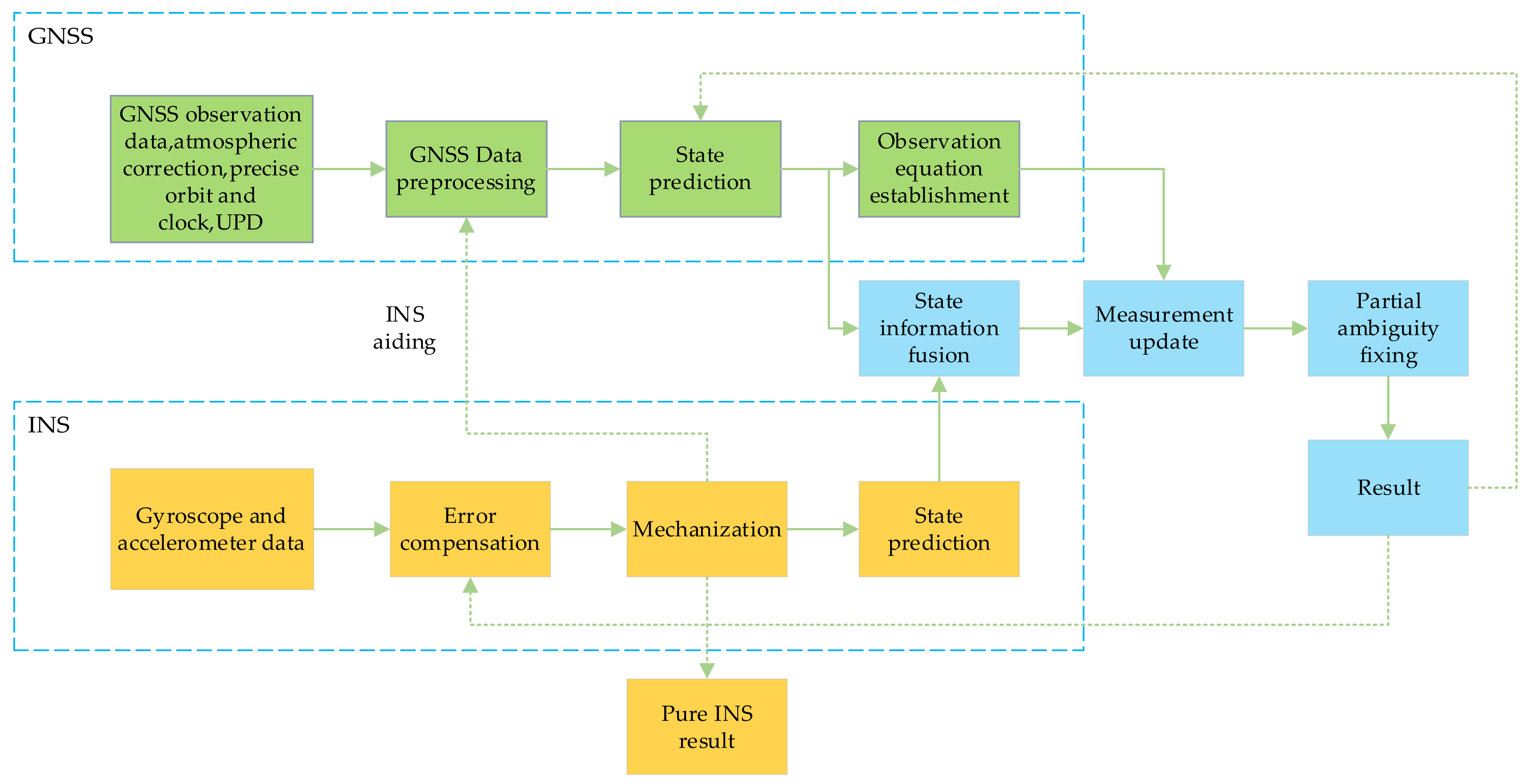
Figure 1 shows the flowchart of PPP-RTK/INS tight integration. Using the observation data, atmospheric enhancement correction, precise satellite orbit and clock, and UPD, the GNSS module mainly consists of data preprocesses, such as cycle slip and gross error detection, state prediction, and observation equation establishment. In the INS module, the initialization of the integrated navigation system is performed using the position provided by GNSS, and then the output data from the gyro and accelerometer are utilized for mechanization to obtain the current INS navigation parameters, which can assist in the cycle slip detection of GNSS preprocessing. Then, the state information of GNSS and INS are fused, and the GNSS observation information is used to measure and update, while the PPP-RTK/INS tight integration fixed solution is obtained with partial ambiguity fixing. After obtaining the gyro and accelerometer biases, the INS mechanization result is corrected to limit the INS error accumulation.
3. Experimental Results and Discussions
In this section, the vehicle data source and experimental processing strategy are first introduced. We then present and analyze the performance of PPP-RTK/INS tight integration in the urban environment. Finally, the performance of PPP-RTK/INS tight integration using low-cost equipment is further analyzed and evaluated.
3.1. Data and Processing Strategy
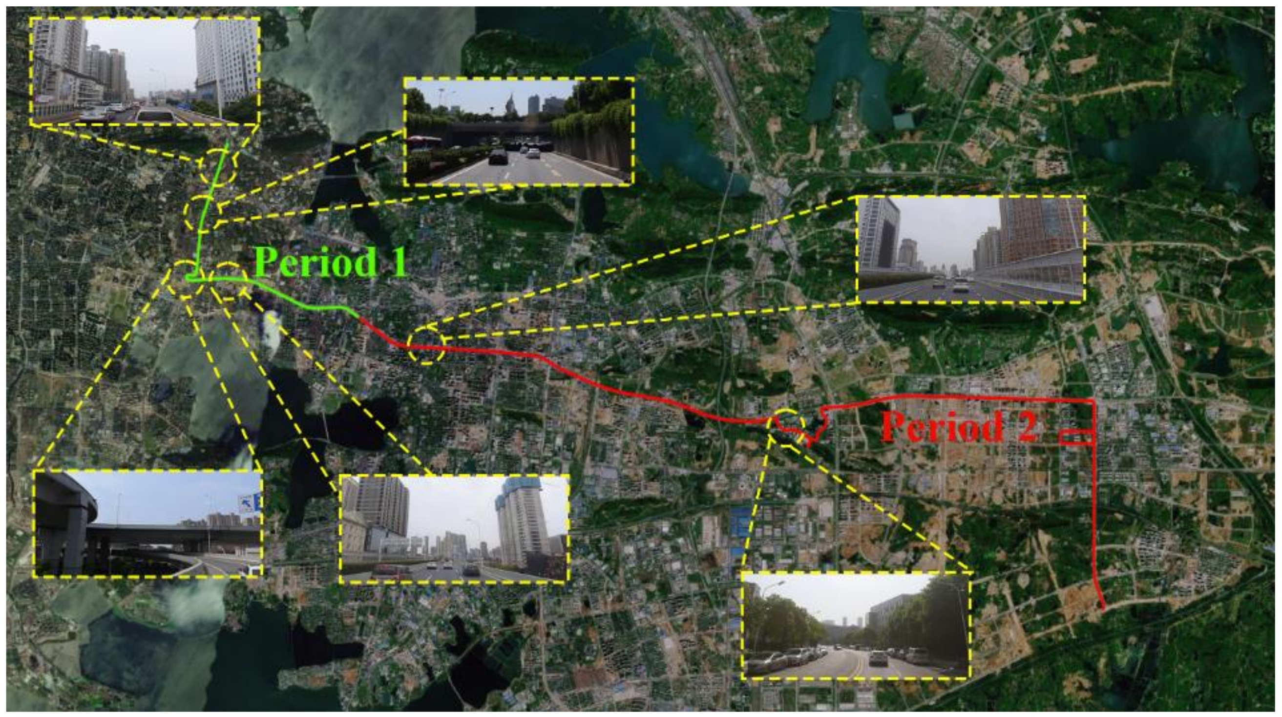
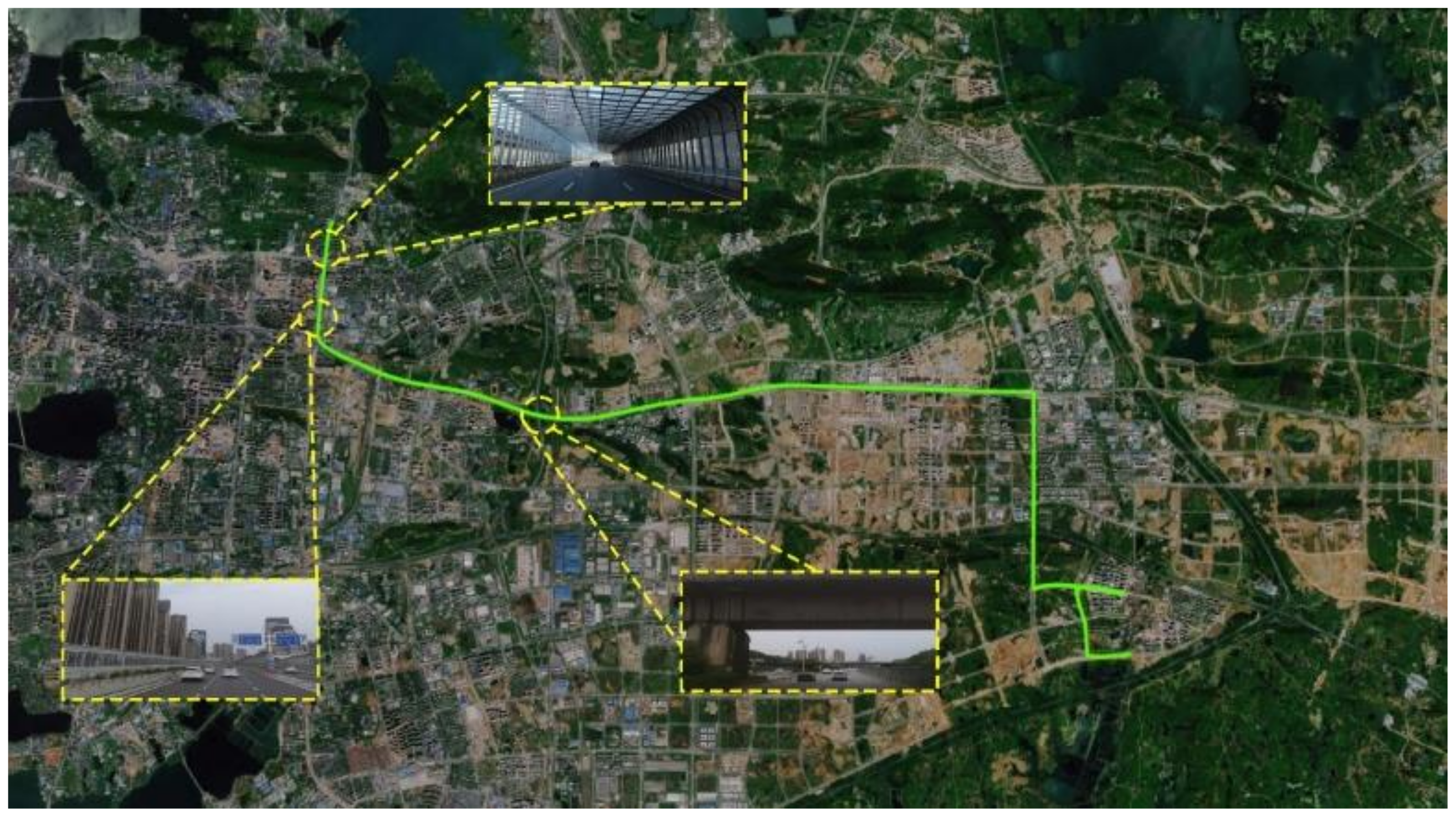
To evaluate the positioning performance of PPP-RTK/INS tight integration, we performed three sets of vehicle experiments in the urban environments of Zhengzhou and Wuhan, China, respectively. Experiment A was conducted in Wuhan from GPS time (GPST) 7:00:00 to 8:04:00 on 13 October 2021, and the trajectory of the vehicle is shown in Figure 2, wherein the green line represents the complex urban environment with seriously blocked GNSS signals, which we name period 1 (0–500 s); the red line represents an improved GNSS observation condition, which we name period 2 (500–3600 s). Experiment B was conducted in the overpasses of Zhengzhou from GPST 5:44:00 to 6:40:00 on 8 July 2022, and its trajectory is shown in Figure 3. During experiment B, GNSS was temporarily interrupted due to passing through several overpasses. Experiment C was also executed in Wuhan from GPST 8:22:30 to 9:00:00 on 13 October 2021, and its trajectory is shown in Figure 4. In the third experiment, the GNSS signal was blocked by residential buildings, overpasses, short tunnels, etc., resulting in several observation interruptions. It should be noted that the static period of three experiments was used for the initial alignment.
The vehicle used in experiment A in Wuhan was equipped with a GNSS antenna (NovAtel GPS-702-GG), a geodetic receiver Septentrio PolaRx5, and a tactical IMU (StarNeto XW-GI7660). The raw GNSS observation was logged at 1 Hz, and that of tactical IMU was 200 Hz. The vehicle equipment used in experiment B in Zhengzhou was equipped with a Trimble Alloy receiver and TRM105000.10 antenna, Novatel CPT7 INS with a built-in MEMS IMU of HG4930CA51. The sampling rates of the Alloy receiver and CPT7 were 1 Hz and 100 Hz, respectively. In experiment C, a MEMS IMU (ADIS-16470) and a low-cost receiver (ublox F9P) were extended based on experiment A, and the NovAtel antenna connected Septentrio PolaRx5 and ublox F9P through a power divider. It should be noted that the low-cost receiver can only receive B1I/B2I signals for BDS and E1/E5b signals for Galileo. The raw data of MEMS IMU were logged at 100 Hz. The precision indexes of the aforementioned three IMUs are shown in Table 1.
During the experiments, a nearby reference station was set in the open environment, and the smoothed solutions of tightly coupled RTK/INS calculated by the high-precision commercial post-processing software Inertial-Explorer (IE) 8.9 was used as the reference. The reference stations used by the server side to generate atmospheric enhancement corrections in Wuhan and Zhengzhou are shown in Figure 5. The average inter-station distance between the reference stations in Wuhan and Zhengzhou is approximately 50 km and 25 km, respectively. The time synchronization of integrated navigation was aligned to GPST, and the shift between the IMU center and the GNSS antenna was calibrated in advance to achieve spatial synchronization. The processing strategies of PPP-RTK are shown in Table 2. The multi-GNSS satellite orbits and clock offsets products from Deutsche GeoForschungsZentrum (GFZ) were used. The UPD products were computed using 200 globally distributed stations from the International GNSS Service (IGS) Multi-GNSS Experiment (MGEX) [40]. Additional inter-frequency biases (IFB) are estimated owing to the inconsistency of the available frequencies and reference frequencies used by GFZ. The positioning results in this paper were obtained using GNSSer software (http://www.gnsser.com/ (accessed on 29 October 2022)).
3.2. Performance of PPP-RTK/INS Tight Integration
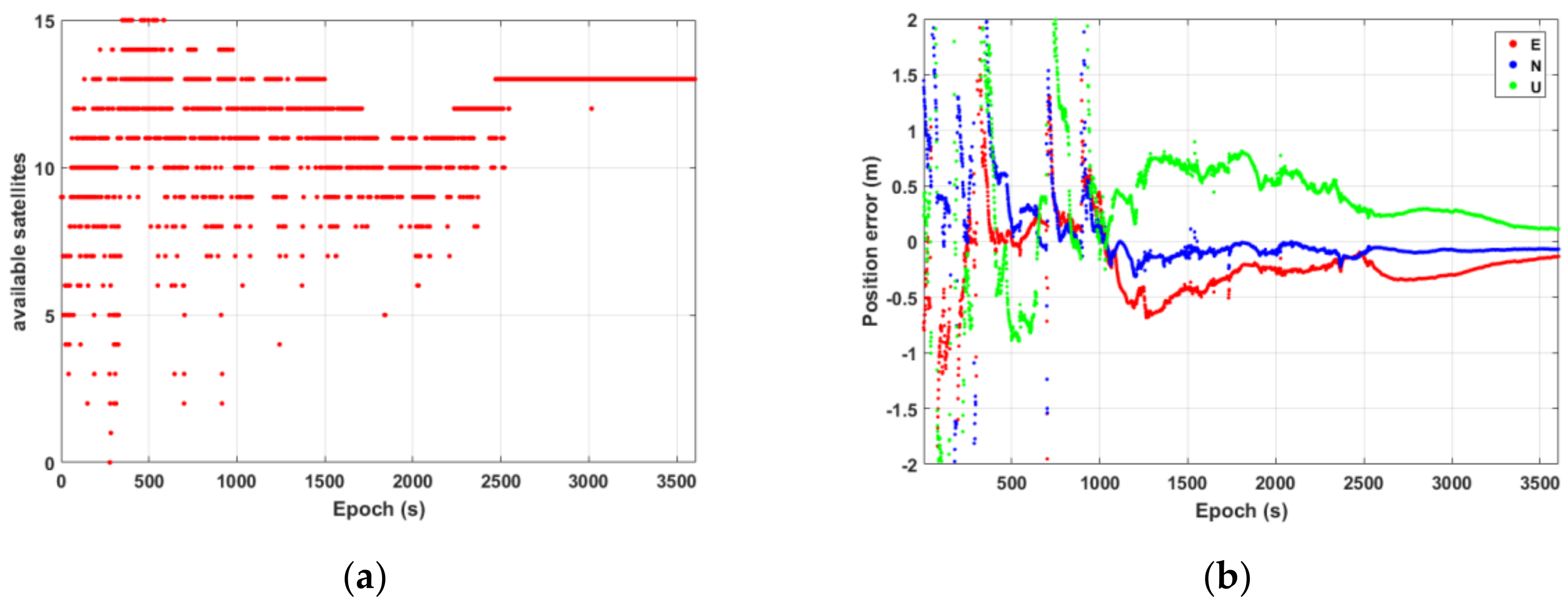
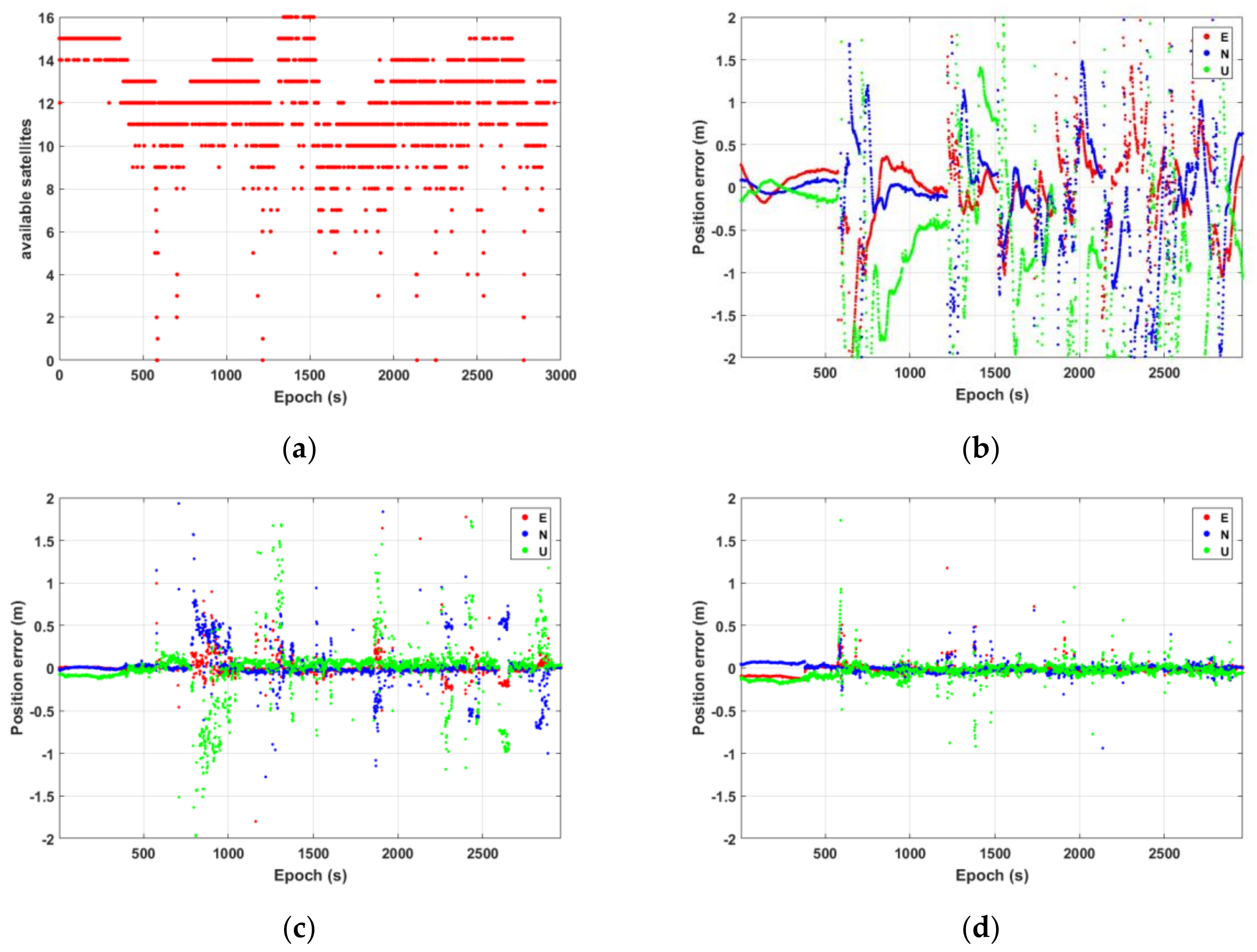
We use experiments A and B to evaluate the positioning performance of PPP-RTK and INS tight integration in the urban environment, and analyze the precision and availability of PPP, PPP-RTK, and TC PPP RTK/INS. Figure 6 shows the number of available satellites and the position accuracy under different positioning modes in experiment A. In this paper, the number of available satellites in Figure 6a refers to the observed satellites with atmospheric corrections in the vehicle-mounted antenna. Figure 6b–d show the position accuracy of float PPP, PPP-RTK, and PPP-RTK/INS, respectively, where the red, blue, and green points represent the position errors in the east, north, and vertical components, respectively. It can be seen from Figure 6b that due to the frequent interruption of GNSS signals in the first 1000 s, the PPP float solutions reconverged several times, and a long time was needed to achieve reconvergence. With an open observation environment after 1000 s, the float PPP gradually converged to decimeter-level accuracy. By adding atmospheric enhancement corrections, PPP-RTK was able to achieve rapid AR and centimeter-level positioning accuracy rapidly, but there also existed many gross errors and positioning deviations under poor GNSS observation conditions. For the TC PPP-RTK/INS model, due to the short-term high accuracy of INS, the assistance of INS can ensure continuous and reliable positioning in the short-term interruption of GNSS and assist GNSS to eliminate gross errors. Although the number of available satellites changed sharply, the position accuracy of TC PPP-RTK/INS did not fluctuate significantly, and most of the positioning errors were within 1 m. Compared with PPP-RTK, the quantities of outliers were reduced.
Table 3 gives the root mean square error (RMS) of PPP-RTK and TC PPP-RTK/INS in the occluded environment (0–500 s) of period 1 and the open environment (500–3600 s) of period 2 in experiment A. Due to the extremely poor GNSS observation conditions in period 1, the number of available satellites fluctuated sharply, resulting in a large deviation of more than 10 m in the positioning accuracy of PPP-RTK. By combining this with INS, the RMS decreased to approximately 0.236 m in the horizontal component and 0.621 m in the vertical component. With a relatively open environment in period 2, both the positioning accuracies of PPP-RTK and PPP-RTK/INS improved a great deal, wherein horizontal position accuracy better than 2 cm and vertical position accuracy better than 5 cm were achieved using TC PPP-RTK/INS.
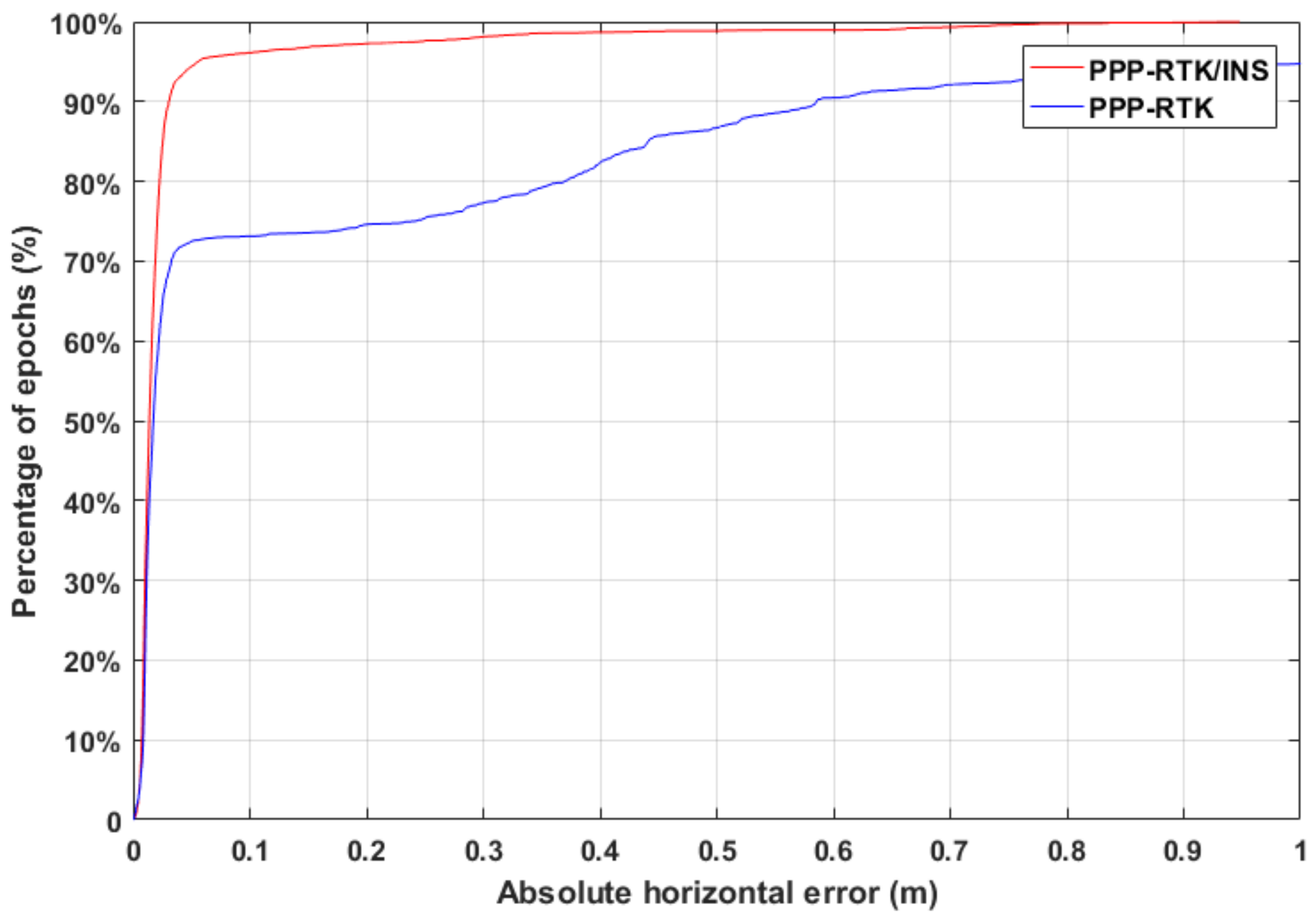
Horizontal positioning accuracy is considered more important for vehicle navigation in the urban environment. Figure 7 shows the positioning availability of PPP-RTK and TC PPP-RTK/INS in experiment A. The blue line and red line represent the percentage of horizontal error that does not exceed the specified threshold for PPP-RTK and TC PPP-RTK/INS, respectively. It can be seen that the initial rise of the curve is rapid, especially within 0.1 m, indicating that, most of the time, the horizontal accuracy can reach the decimeter level. Besides, the initial coincidence of the two curves also indicates that the high-accuracy positioning of the vehicle mainly depends on the conditions of GNSS observation. Under the open observation environment, no significant difference in the positioning accuracy between PPP-RTK and TC PPP-RTK/INS existed, and both of them were able to reach an accuracy of several centimeters. However, when GNSS signals were interrupted intermittently and the number of available satellites varied drastically, the positioning accuracy could be maintained with the augmentation of INS, and hence, the positioning availability of TC PPP-RTK/INS is better than that of PPP-RTK.
Furthermore, Table 4 gives the statistical percentage of positioning availability with horizontal errors of less than 20 and 50 cm. In experiment A, 74.6% of the total epoch for PPP-RTK reached a horizontal accuracy better than 20 cm, and it was increased to 97.3% for TC PPP-RTK/INS. When the threshold was enlarged to 50 cm, 86.7% of the total epoch for PPP-RTK and 98.9% of the total epoch for TC PPP-RTK/INS met the threshold. Hence, INS played an obvious auxiliary role in the semi-occlusion of GNSS.
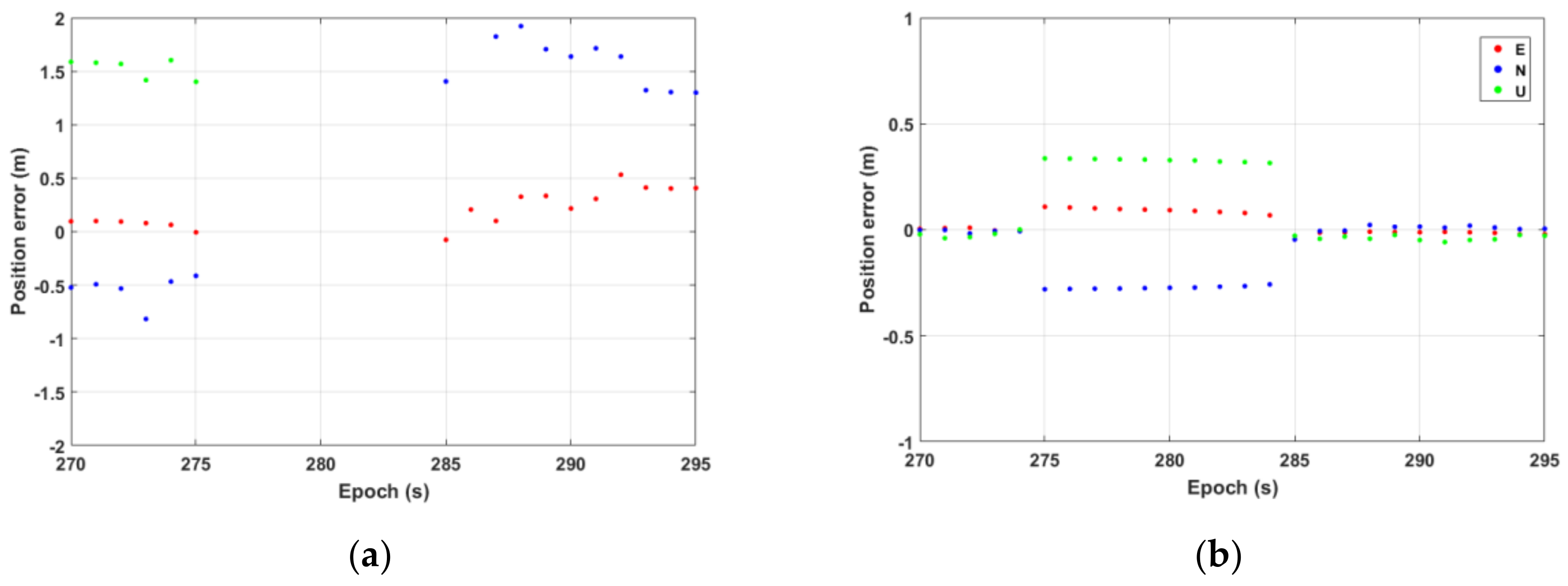
In experiment A, 10 s signal interruption existed between 270 s and 295 s. To show the auxiliary role of INS more clearly, the position error sequence of PPP-RTK and TC PPP-RTK/INS from 270 s to 295 s is enlarged in Figure 8. From 270 s to 275 s, the satellite signal was blocked, resulting in a sharp decrease in the number of available satellites, poor satellite geometry, and severe multipath errors, and hence, the positioning error of PPP-RTK decreased to nearly 2 m. From 275 s to 285 s, the GNSS signal was lost, and PPP-RTK could not obtain the positioning result, but TC PPP-RTK/INS can maintain the positioning accuracy to several decimeters. When the GNSS signal was tracked again from 285 s, the ambiguities of PPP-RTK were fixed wrongly, resulting in a large error of more than 2 m in the U component. However, the ambiguities were instantaneously re-fixed with the aid of INS, therefore the positioning accuracy of TC PPP-RTK/INS was restored to the level of several centimeters.
Since the observation environment of experiment B is different from experiment A, the vehicle was driven at a constant speed on the viaduct. Figure 9 further shows the number of available satellites and the positioning errors sequence of float PPP, PPP-RTK, and TC PPP-RTK/INS in experiment B. Most of the trajectory in experiment B was an open environment, and GNSS observation conditions were good most of the time, but there were multiple signal interruptions during the experiment. The float PPP achieved a positioning accuracy of better than 0.3 m in the initial open environment, while float PPP continued to re-converge due to frequent signal blocks. Furthermore, PPP-RTK had a large error when GNSS was blocked. Compared with PPP-RTK, the reconvergence time was shortened further, and the number of outliers was reduced significantly using TC PPP-RTK/INS.
Figure 10 shows the positioning availability of PPP-RTK and TC PPP-RTK/INS in experiment B. Compared with experiment A, the coincidence rate of PPP-RTK and TC PPP-RTK/INS curves is higher, which is because experiment B was conducted mainly on the overpasses, and the majority of the observation environment was open. The statistical results show that the percentage of available GNSS satellites totaling more than 8 in experiment A and experiment B was 93.3% and 95.1%, respectively. INS played an assistance role in the condition of signal blocks when the vehicle passed through several overpasses.
Table 5 gives the statistical percentages of positioning availability with a horizontal error of less than 20 and 50 cm in experiment B. Moreover, 81.4% of the total epochs for PPP-RTK reached a horizontal accuracy of better than 20 cm, and it increased to 97.9% for TC PPP-RTK/INS. When the threshold was enlarged to 50 cm, 88.8% of the total epoch for PPP-RTK and 99.7% of the total epoch for TC PPP-RTK/INS met the threshold. All the results were better than those of experiment A. Besides, while GNSS is vulnerable to being blocked in an overpass scenario, INS plays an obvious role in using TC mode.
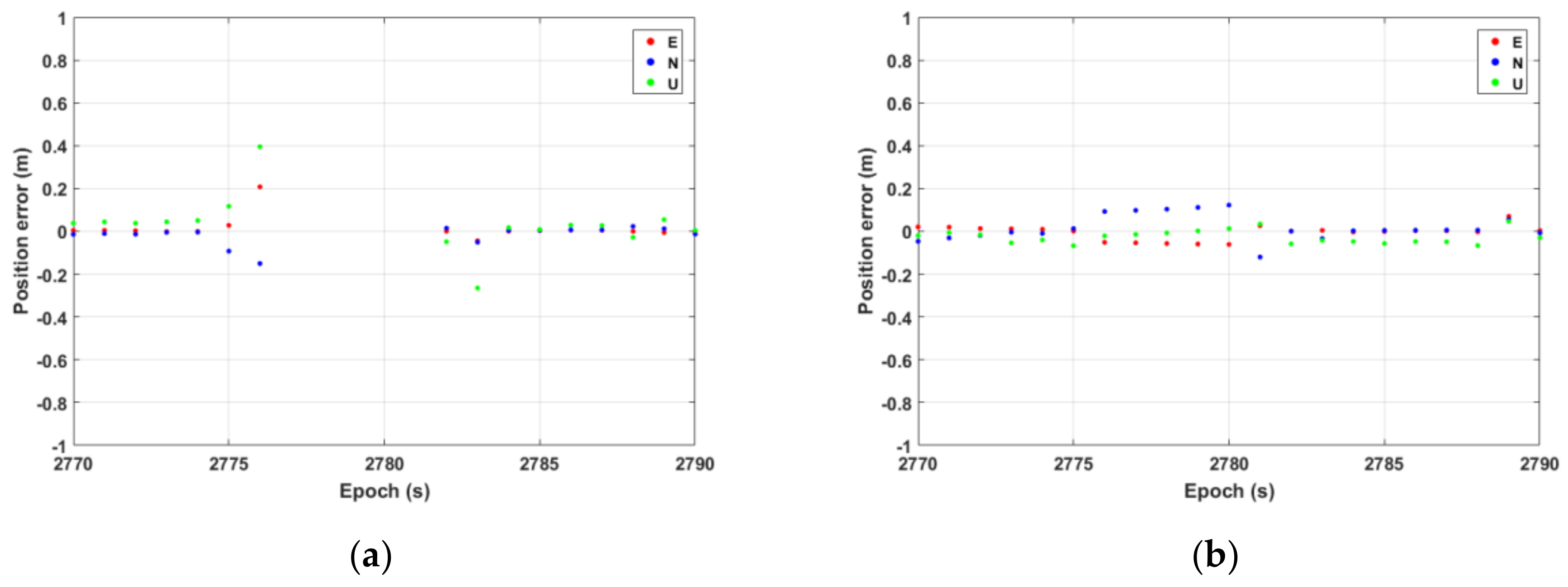
Additionally, there are several GNSS short-term interruptions in experiment B. Figure 11 shows the positioning accuracy of PPP-RTK and TC PPP-RTK/INS at 2770–2790 s in experiment B, in which the GNSS was interrupted for 5 s. The recursive errors of INS were all within 0.2 m due to a shorter interruption of the GNSS signal. After GNSS resumed observation, both PPP-RTK and TC PPP-RTK/INS could achieve rapid AR, but TC PPP-RTK/INS showed higher accuracy than that of PPP-RTK at 2770–2790 s.
3.3. Tight Integration of PPP-RTK/INS Using Low-Cost Equipment
The performance of TC PPP-RTK/INS with a geodetic receiver and a tactical IMU in an urban environment was discussed in Section 3.2. To further analyze the performance of a low-cost receiver and MEMS IMU, four schemes are utilized here, including the geodetic receiver and tactical IMU combination (SEPT-XW for short), the geodetic receiver and low-cost MEMS IMU combination (SEPT-ADIS for short), the low-cost receiver and tactical IMU combination (F9P-XW for short), and the combination of a low-cost receiver and low-cost MEMS IMU (F9P-ADIS for short).
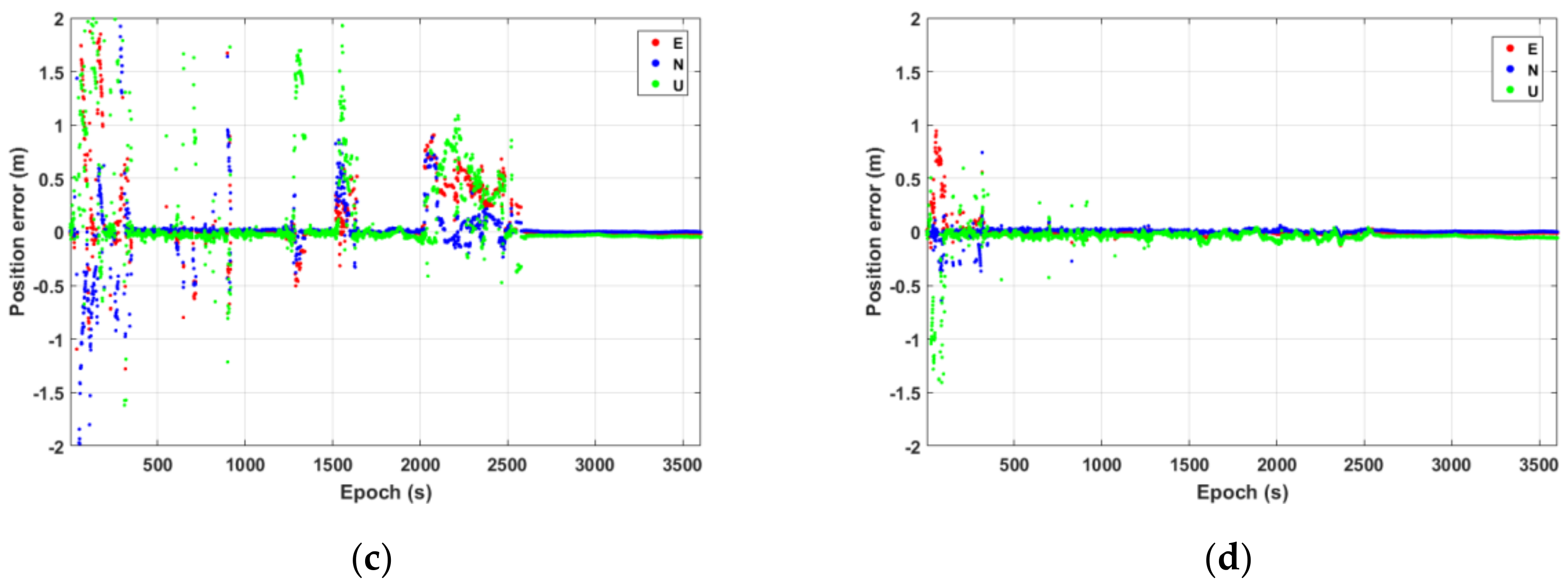
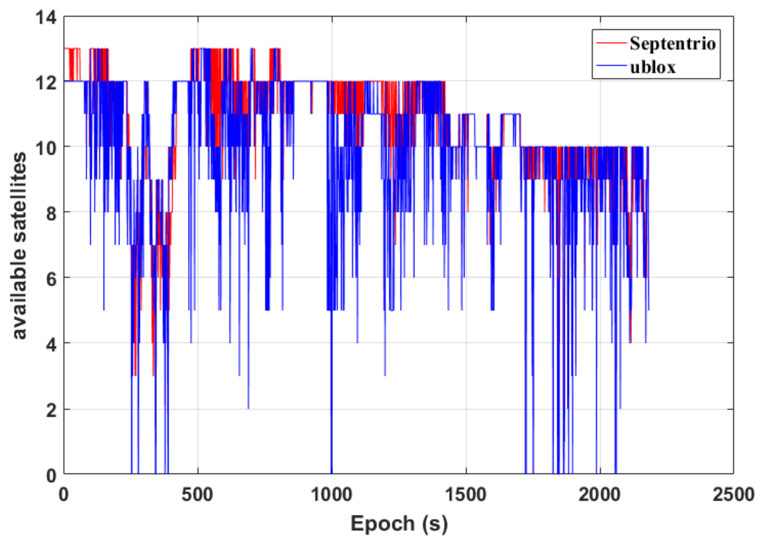
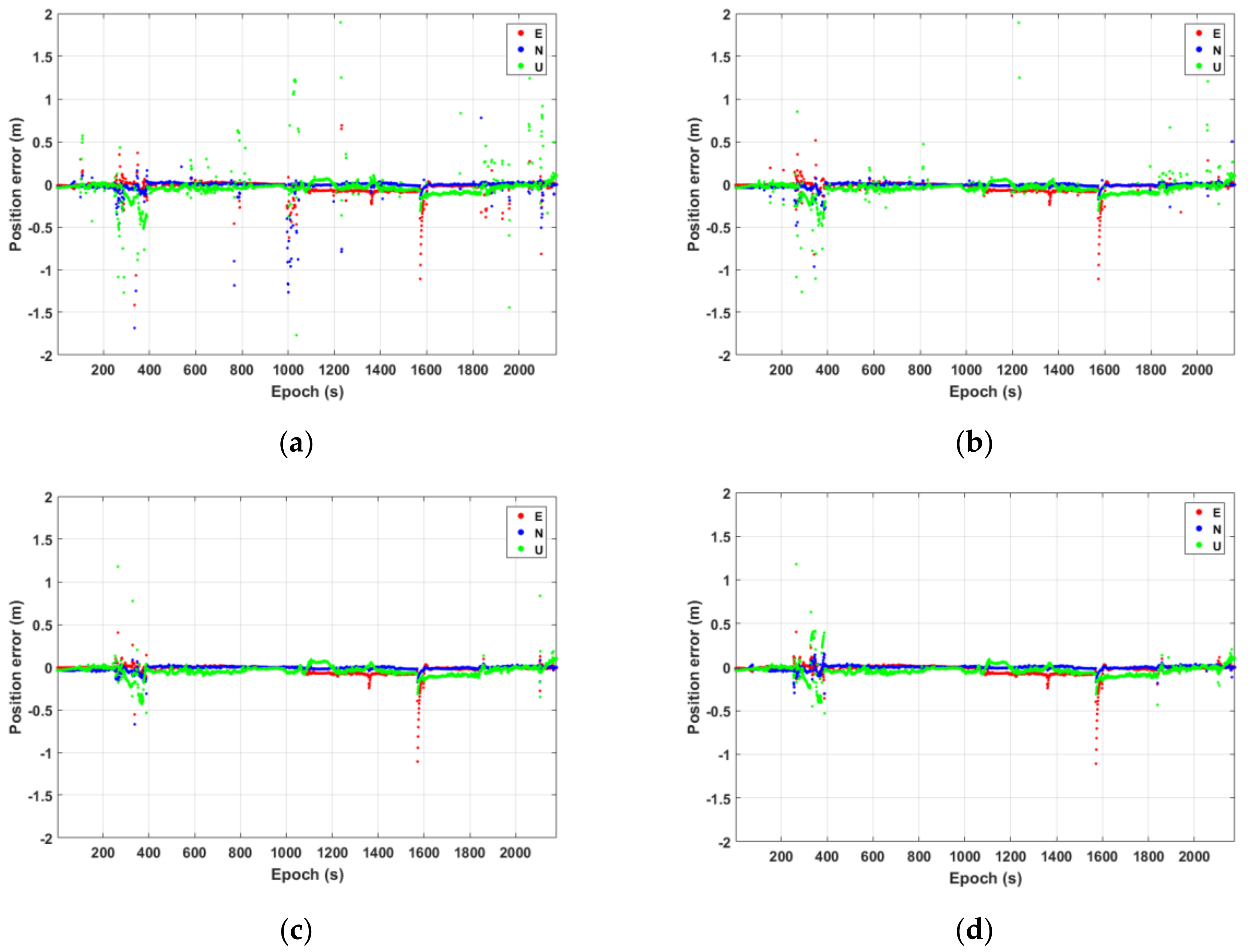
Figure 12 shows the number of available satellites and the position accuracy of TC PPP-RTK/INS under different schemes. The red and blue lines represent the number of available satellites of Septentrio PolaRx5 and ublox F9P receivers, respectively. The position errors of F9P-ADIS, F9P-XW, SEPT-ADIS, and SEPT-XW are shown in Figure 13a–d, respectively. As shown in Figure 12, the number of available satellites of the ublox F9P receiver was less than that of the Septentrio receiver most of the time, and the statistical results show that the average number of available satellites of the Septentrio PolaRx5 receiver was 10.77, or 9.95 using ublox F9P receiver. Compared with the SEPT-XW scheme, F9P-ADIS had more gross errors, but there was no significant difference between them in most epochs. Compared with F9P-ADIS, F9P-XW eliminated some gross errors using the tactical IMU. When it was close to 1600 s, the E component of the three schemes all showed a large deviation, which may be caused by the undetected gross errors of GNSS observations.
Table 6 gives the RMS and arithmetic mean error of the above four schemes, and the arithmetic mean error is the average of the absolute value. RMS is susceptible to interference with gross errors, so the RMS of the schemes is quite different, while the arithmetic mean error reflects the average of the position accuracy, so the arithmetic mean error of the schemes is relatively close. The statistical results show that TC PPP-RTK/INS using low-cost equipment in an urban environment can achieve decimeter-level positioning accuracy, but it is susceptible to environmental interference.
To show the enhancement effect of IMU and compare the performance of the equipment with different costs, Table 7 gives the statistical ambiguity fixing percentage of PPP-RTK and TC PPP-RTK/INS. The ambiguity fixing percentage here is defined as the percentage of the correctly fixed epochs over the total epochs [32]. In the urban environment, the low-cost receiver suffered from severe interference, and the quality of GNSS observation data was much poorer than that of geodetic receivers, such as missing the second frequency observations or carrier-phase observations. Therefore, the total epochs and fixed epochs of the low-cost receiver were fewer than those of the geodetic receiver. However, the fixing percentage of F9P-ADIS was slightly lower than that of F9P, and this is because the number of total epochs of TC PPP-RTK/INS was much higher than that of PPP-RTK.
- The RMS of F9P-ADIS and F9P-XW were (0.096, 0.105, 0.256) and (0.073, 0.046, 0.223), while they were (0.068, 0.032, 0.097) and (0.068, 0.027, 0.088) using SEPT-ADIS and SEPT-XW, respectively. Furthermore, the ambiguity-fixing percentages of F9P-ADIS and F9P-XW were 84.90% and 87.79%, while they were 93.12% and 93.21% using SEPT-ADIS and SEPT-XW, respectively. Hence, compared with the scheme using the low-cost receiver, the improvement using the geodetic receiver is obvious whether using MEMS IMU or tactical IMU.
- Comparing the positioning accuracy and ambiguity fixing percentages of the schemes using MEMS IMU and tactical IMU, tactical IMU shows a significant improvement for the low-cost receiver and a slight improvement for the geodetic receiver.
- Considering the positioning accuracy and ambiguity-fixing percentages of F9P-ADIS, F9P-XW, and SEPT-ADIS, it can be found that, compared with the scheme using the low-cost receiver and MEMS IMU, the improvement using the geodetic receiver is more obvious than that of using the tactical IMU.
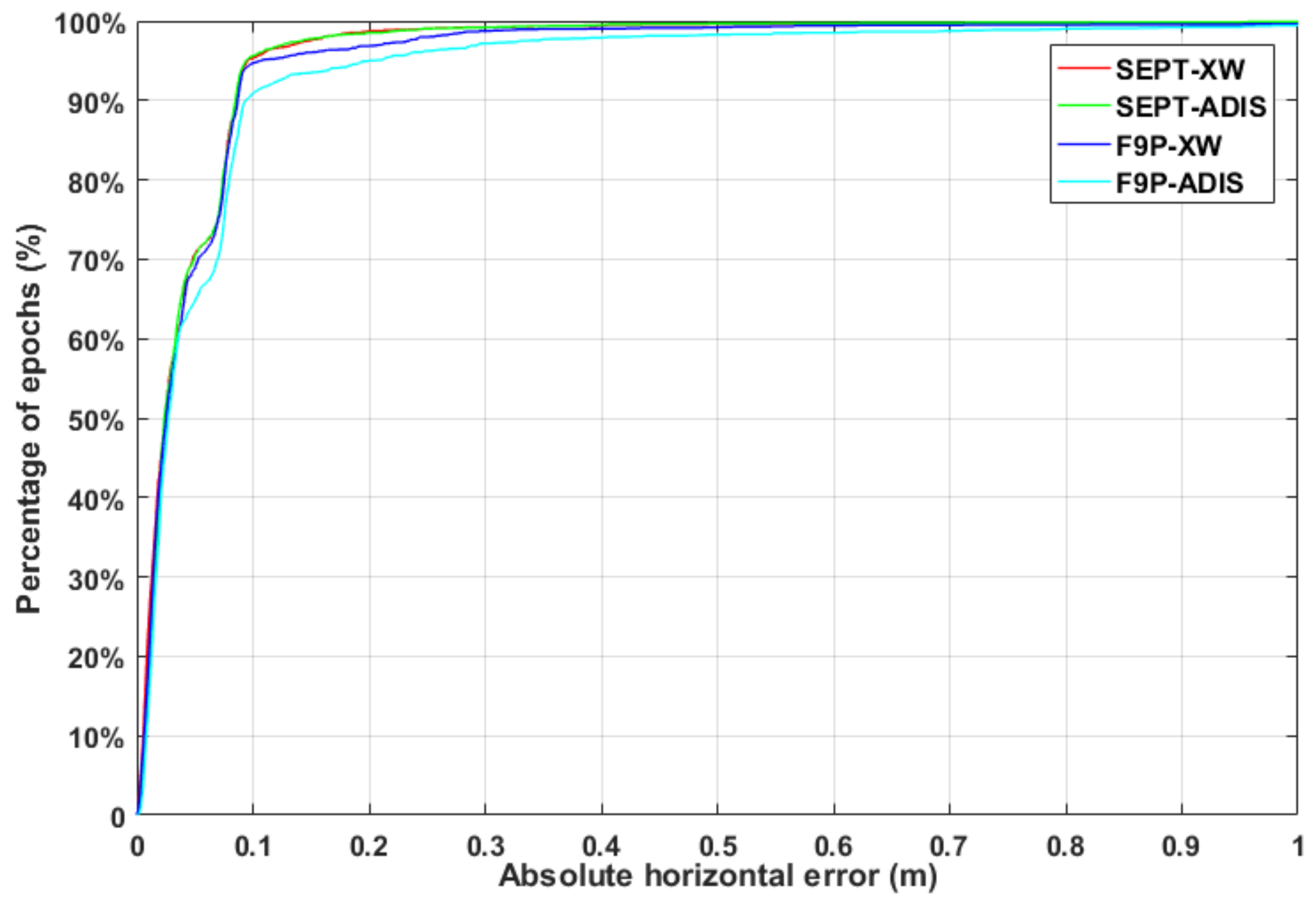
Figure 14 shows the positioning availability under different schemes, in which the red, green, blue, and cyan lines represent SEPT-XW, SEPT-ADIS, F9P-XW, and F9P-ADIS, respectively. It can be seen that there was no significant difference between SEPT-XW and SEPT-ADIS schemes, but there was a significant difference between the scheme using the geodetic receiver and low-cost receiver, indicating that the observation quality of GNSS data had a significant influence on the TC PPP-RTK/INS. At the same time, obvious differences can also be seen between the two schemes of F9P-ADIS and F9P-XW using the low-cost receiver, indicating that the GNSS data observation quality received by the low-cost receiver was poor, and by combining with tactical IMU, the positioning accuracy can be improved, and some gross errors can be removed.
4. Conclusions
In this paper, TC PPP-RTK/INS is comprehensively evaluated using rich vehicle-mounted data in the urban environment, the performance during different GNSS short-time outages is discussed, and the positioning performance of a low-cost receiver and MEMS IMU is compared. The tight integration of PPP-RTK/INS shows great application potential in urban environments, which can ensure continuous and reliable positioning in the short interruptions of GNSS.
By using precise atmospheric corrections, PPP-RTK can achieve rapid AR and shorten the convergence time compared with traditional PPP. However, in the GNSS-sheltered environment, the positioning performance of PPP-RTK is significantly degraded. By combining it with INS, it can achieve a positioning accuracy of 2 cm in the horizontal component and 5 cm in the vertical component in an open environment and decimeter-level accuracy in a sheltered environment. Hence, in our experiments, more than 95% of the epochs can ensure that the horizontal accuracy is higher than 20 cm. In addition, it is found that the assistance of INS mainly lies in the realization of decimeter-level positioning, and the high-precision positioning mainly depends on GNSS observation conditions.
The performance of the low-cost receiver and MEMS IMU is also analyzed. The average number of available satellites for the low-cost receiver was 9.95, while the number for the geodetic receiver was 10.77. Compared with the low-cost receiver, the improvement with the geodetic receiver is obvious whether using MEMU IMU or tactical IMU. Moreover, compared with MEMS IMU, tactical IMU has a significant improvement for the low-cost receiver and a slight improvement for the geodetic receiver. Finally, the improvements in positioning accuracy and ambiguity fixing rate using the geodetic receiver were more significant than tactical IMU.
Low-cost devices are widely used because of their low weight and small size. However, it is more vulnerable to interference in the urban environment. Therefore, the recognition and processing of multipath signals will be investigated in the future to improve the performance of low-cost devices. Meanwhile, when the GNSS is interrupted for a long time, the INS error will accumulate rapidly. It is not feasible to rely on INS only, so it is necessary to merge other sensors.
Author Contributions
All authors contributed to this work. Conceptualization, L.L. (Luguang Lai) and L.L. (Linyang Li); methodology, L.L. (Luguang Lai), T.X., Z.C. and L.L. (Linyang Li); software, L.L. (Luguang Lai), D.Z. and L.L. (Linyang Li); validation, L.L. (Luguang Lai), Z.C., W.G. and L.L. (Linyang Li); writing—original draft preparation, L.L. (Luguang Lai) and Z.C.; writing—review and editing, D.Z., W.G. and L.L. (Linyang Li). All authors have read and agreed to the published version of the manuscript.
Funding
This research was funded by the National Nature Science Foundation of China (Grant No. 42104033, 41774037) and the Postdoctoral Science Foundation of China (Grant Nos. 2022M712442).
Data Availability Statement
The datasets used in this study are managed by the Institute of Surveying and Mapping, Information Engineering University, Zhengzhou, China and can be available on request from the corresponding author.
Acknowledgments
The MGEX is acknowledged for offering GNSS data and products. We would also like to thank the GREAT team at Wuhan University for providing data.
Conflicts of Interest
The authors declare no conflict of interest.
References
- Li, B.; Chen, G. Precise cooperative positioning for vehicles with GNSS and INS integration. Acta Geod. Cartogr. Sin. 2022, 51, 1708–1716. [Google Scholar]
- Rizos, C. Network RTK research and implementation: A geodetic perspective. J. Glob Position Syst. 2002, 1, 144–150. [Google Scholar] [CrossRef] [Green Version]
- Zumberge, J.; Heflin, M.; Jefferson, D.; Watkins, M.; Webb, F. Precise point positioning for the efficient and robust analysis of GPS data from large networks. J. Geophys. Res. 1997, 102, 5005–5017. [Google Scholar] [CrossRef] [Green Version]
- Kouba, J.; Heroux, P. Precise Point Positioning Using IGS Orbit and Clock Products. GPS Solut. 2001, 5, 12–28. [Google Scholar] [CrossRef]
- Li, X.; Li, X.; Yuan, Y.; Zhang, K.; Zhang, X.; Wickert, J. Multi-GNSS phase delay estimation and PPP ambiguity resolution: GPS, BDS, GLONASS, Galileo. J. Geod. 2017, 92, 579–608. [Google Scholar] [CrossRef]
- Wübbena, G.; Schmitz, M.; Bagge, A. PPP-RTK: Precise Point Positioning Using State-Space Representation in RTK networks. In Proceedings of the 18th International Technical Meeting of the Satellite Division of The Institute of Navigation (ION GNSS 2005), Long Beach, CA, USA, 13–16 September 2005; pp. 2584–2594. [Google Scholar]
- Teunissen, P.J.G.; Odijk, D.; Zhang, B. PPP-RTK: Results of CORS network-based PPP with integer ambiguity resolution. J. Aeronaut. Astronaut. Aviat. 2010, 42, 223–230. [Google Scholar]
- Schönemann, E.; Becker, M.; Springer, T. A new approach for GNSS analysis in a multi-GNSS and multi-signal environment. J. Geod. 2011, 1, 204–214. [Google Scholar] [CrossRef] [Green Version]
- Zhang, B.; Chen, Y.; Yuan, Y. PPP-RTK based on undifferenced and uncombined observations: Theoretical and practical aspects. J. Geod. 2019, 93, 1011–1024. [Google Scholar] [CrossRef]
- Gu, S.; Dai, C.; Fang, W.; Zheng, F.; Wang, Y.; Zhang, Q.; Lou, Y.; Niu, X. Multi-GNSS PPP/INS tightly coupled integration with atmospheric augmentation and its application in urban vehicle navigation. J. Geod. 2021, 95, 64. [Google Scholar] [CrossRef]
- Hu, A.; Li, Z.; Carter, B.; Wu, S.; Wang, X.; Norman, R.; Zhang, L. Helmert-VCE-aided fast-WTLS approach for global ionospheric VTEC modelling using data from GNSS, satellite altimetry and radio occultation. J. Geod. 2019, 93, 877–888. [Google Scholar] [CrossRef]
- Zhou, P.; Wang, J.; Nie, Z.; Gao, Y. Estimation and representation of regional atmospheric corrections for augmenting real-time single-frequency PPP. GPS Solut. 2020, 24, 7. [Google Scholar] [CrossRef]
- Zhang, B.; Teunissen, P.J.G.; Odijk, D. A Novel Un-differenced PPP-RTK Concept. J. Navig. 2011, 64, S180–S191. [Google Scholar] [CrossRef]
- Li, X.; Zhang, X.; Ge, M. Regional reference network augmented precise point positioning for instantaneous ambiguity resolution. J. Geod. 2011, 85, 151–158. [Google Scholar] [CrossRef]
- Geng, J.; Teferle, F.N.; Meng, X.; Dodson, A.H. Towards PPP-RTK: Ambiguity resolution in real-time precise point positioning. Adv. Space Res. 2011, 47, 1664–1673. [Google Scholar] [CrossRef] [Green Version]
- Tao, J.; Liu, J.; Hu, Z.; Zhao, Q.; Chen, G.; Ju, B. Initial Assessment of the BDS-3 PPP-B2b RTS compared with the CNES RTS. GPS Solut. 2021, 25, 131. [Google Scholar] [CrossRef]
- Wang, S.; Li, B.; Gao, Y.; Gao, Y.; Guo, H. A comprehensive assessment of interpolation methods for regional augmented PPP using reference networks with different scales and terrains. Measurement 2020, 150, 107067. [Google Scholar] [CrossRef]
- Wang, K.; Khodabandeh, A.; Teunissen, P.J.G. A study on predicting network corrections in PPP-RTK processing. Adv. Space Res. 2017, 60, 1463–1477. [Google Scholar] [CrossRef] [Green Version]
- Nadarajah, N.; Khodabandeh, A.; Wang, K.; Choudhury, M.; Teunissen, P.J.G. Multi-GNSS PPP-RTK: From Large- to Small-Scale Networks. Sensors 2018, 18, 1078. [Google Scholar] [CrossRef] [Green Version]
- Li, P.; Cui, B.; Hu, J.; Liu, X.; Zhang, X.; Ge, M.; Schuh, H. PPP-RTK considering the ionosphere uncertainty with cross-validation. Satell. Navig. 2022, 3, 10. [Google Scholar] [CrossRef]
- Zhang, B.; Hou, P.; Zha, J.; Liu, T. Integer-estimable FDMA model as an enabler of GLONASS PPP-RTK. J. Geod. 2021, 95, 91. [Google Scholar] [CrossRef]
- Li, Z.; Chen, W.; Ruan, R.; Liu, X. Evaluation of PPP-RTK based on BDS-3/BDS-2/GPS observations: A case study in Europe. GPS Solut. 2020, 24, 1–12. [Google Scholar] [CrossRef]
- Psychas, D.; Teunissen, P.J.G.; Verhagen, S. A Multi-Frequency Galileo PPP-RTK Convergence Analysis with an Emphasis on the Role of Frequency Spacing. Remote Sens. 2021, 13, 3077. [Google Scholar] [CrossRef]
- Li, X.; Wang, B.; Li, X.; Huang, J.; Lyu, H.; Han, X. Principle and performance of multi-frequency and multi-GNSS PPP-RTK. Satell. Navig. 2022, 3, 7. [Google Scholar] [CrossRef]
- Shin, E.H.; Scherzinger, B. Inertially Aided Precise Point Positioning. In Proceedings of the 22nd International Technical Meeting of the Satellite Division of the Institute of Navigation (ION GNSS 2009), Svannah, GA, USA, 22–25 September 2009; pp. 1892–1897. [Google Scholar]
- Zhang, Y.; Gao, Y. Integration of INS and Un-Differenced GPS Measurements for Precise Position and Attitude Determination. J. Navig. 2008, 61, 87–97. [Google Scholar] [CrossRef]
- Rabbou, M.A.; El-Rabbany, A. Tightly coupled integration of GPS precise point positioning and MEMS-based inertial systems. GPS Solut. 2015, 19, 601–609. [Google Scholar] [CrossRef]
- Gao, Z.; Zhang, H.; Ge, M.; Niu, X.; Shen, W.; Wickert, J.; Schuh, H. Tightly coupled integration of multi-GNSS PPP and MEMS inertial measurement unit data. GPS Solut. 2017, 21, 377–391. [Google Scholar] [CrossRef]
- Reuper, B.; Becker, M.; Leinen, S. Benefits of Multi-Constellation/Multi-Frequency GNSS in a Tightly Coupled GNSS/IMU/Odometry Integration Algorithm. Sensors 2018, 18, 3052. [Google Scholar] [CrossRef] [Green Version]
- Liu, S.; Sun, F.; Zhang, L.; Li, W.; Zhu, X. Tight integration of ambiguity-fixed PPP and INS: Model description and initial results. GPS Solut. 2016, 20, 39–49. [Google Scholar] [CrossRef]
- Du, Z.; Chai, H.; Xiao, G.; Xiang, M.; Shi, M. The Realization and Evaluation of PPP Ambiguity Resolution with INS Aiding in Marine Survey. Mar. Geod. 2022, 44, 136–156. [Google Scholar] [CrossRef]
- Zhang, X.; Zhu, F.; Zhang, Y.; Mohamed, F.; Zhou, W. The improvement in integer ambiguity resolution with INS aiding for kinematic precise point positioning. J. Geod. 2019, 93, 993–1010. [Google Scholar] [CrossRef]
- Li, X.; Li, X.; Huang, J.; Shen, Z.; Wang, B.; Yuan, Y.; Zhang, K. Improving PPP-RTK in urban environment by tightly coupled integration of GNSS and INS. J. Geod. 2021, 95, 132. [Google Scholar] [CrossRef]
- Li, B.; Mi, J.; Zhu, H.; Gu, S.; Xu, Y.; Wang, H.; Yang, L.; Chen, Y.; Pang, Y. BDS-3/GPS/Galileo OSB Estimation and PPP-AR Positioning Analysis of Different Positioning Models. Remote Sens. 2022, 14, 4207. [Google Scholar] [CrossRef]
- Saastamoinen, J. Atmospheric correction for the troposphere and stratosphere in radio ranging satellites. J. Geophys. Res. Atmosph. 1972, 15, 247–251. [Google Scholar]
- Teunissen, P.J.G. The least-squares ambiguity decorrelation adjustment: A method for fast GPS integer ambiguity estimation. J. Geod. 1995, 70, 65–82. [Google Scholar] [CrossRef]
- Psychas, D.; Verhagen, S. Real-Time PPP-RTK Performance Analysis Using Ionospheric Corrections from Multi-Scale Network Configurations. Sensors 2020, 20, 3012. [Google Scholar] [CrossRef]
- Du, Z.; Chai, H.; Xiao, G.; Yin, X.; Wang, M.; Xiang, M. Analyzing the contributions of multi-GNSS and INS to the PPP-AR outage re-fixing. GPS Solut. 2021, 25, 81. [Google Scholar] [CrossRef]
- Li, P.; Zhang, X. Precise point positioning with partial ambiguity fixing. Sensors 2015, 15, 13627–13643. [Google Scholar] [CrossRef] [Green Version]
- Montenbruck, O.; Steigenberger, P.; Prange, L.; Deng, Z.; Zhao, Q.; Perosanz, F.; Romero, I.; Noll, C.; Stürze, A.; Weber, G.; et al. The Multi-GNSS Experiment (MGEX) of the International GNSS Service (IGS)—Achievements, Prospects and Challenges. Adv. Space Res. 2017, 59, 1671–1697. [Google Scholar] [CrossRef]
Figure 1.
Flow chart of PPP-RTK/INS tight integration.

Figure 2.
The trajectory of experiment A.

Figure 3.
The trajectory of experiment B.

Figure 4.
The trajectory of experiment C.

Figure 5.
The distribution of reference stations used in Wuhan and Zhengzhou experiments to generate atmospheric corrections. (a) Reference station with an average inter-station distance of approximately 50 km in Wuhan. (b) Reference station with an average inter-station distance of approximately 25 km in Zhengzhou.

Figure 6.
(a) The number of available satellites in experiment A. (b) Position errors sequence of float PPP. (c) Position errors sequence of PPP−RTK. (d) Position errors sequence of TC PPP−RTK/INS.
Figure 6.
(a) The number of available satellites in experiment A. (b) Position errors sequence of float PPP. (c) Position errors sequence of PPP−RTK. (d) Position errors sequence of TC PPP−RTK/INS.


Figure 7.
The percentage of horizontal positioning error that does not exceed the specified threshold in experiment A.
Figure 7.
The percentage of horizontal positioning error that does not exceed the specified threshold in experiment A.

Figure 8.
Position errors in the E, N, and U components from 270 s to 295 s in experiment A. (a) PPP−RTK. (b) TC PPP−RTK/INS.
Figure 8.
Position errors in the E, N, and U components from 270 s to 295 s in experiment A. (a) PPP−RTK. (b) TC PPP−RTK/INS.

Figure 9.
(a) The number of available satellites in experiment B. (b) Position error sequence of float PPP. (c) Position error sequence of PPP−RTK. (d) Position error sequence of TC PPP−RTK/INS.
Figure 9.
(a) The number of available satellites in experiment B. (b) Position error sequence of float PPP. (c) Position error sequence of PPP−RTK. (d) Position error sequence of TC PPP−RTK/INS.

Figure 10.
The percentage of horizontal positioning error that does not exceed the specified threshold in experiment B.
Figure 10.
The percentage of horizontal positioning error that does not exceed the specified threshold in experiment B.

Figure 11.
Position errors in the E, N, and U components from 2770 s to 2790 s in experiment B. (a) PPP−RTK. (b) TC PPP−RTK/INS.
Figure 11.
Position errors in the E, N, and U components from 2770 s to 2790 s in experiment B. (a) PPP−RTK. (b) TC PPP−RTK/INS.

Figure 12.
Available satellites during experiment C using different receivers.

Figure 13.
(a) Position accuracy of F9P−ADIS. (b) Position accuracy of F9P−XW. (c) Position accuracy of SEPT−ADIS. (d) Position accuracy of SEPT−XW.
Figure 13.
(a) Position accuracy of F9P−ADIS. (b) Position accuracy of F9P−XW. (c) Position accuracy of SEPT−ADIS. (d) Position accuracy of SEPT−XW.

Figure 14.
The percentage of horizontal positioning error does not exceed the specified threshold under different schemes in experiment C.
Figure 14.
The percentage of horizontal positioning error does not exceed the specified threshold under different schemes in experiment C.


Table 1.
Precision indexes of IMUs used in Wuhan and Zhengzhou vehicle-mounted experiment.
| IMU | Sampling Rates (Hz) | Accelerometer Bias (mGal) | ||
|---|---|---|---|---|
| XW-GI7660 | 200 | 0.3 | 100 | 0.01 |
| ADIS-16470 | 100 | 8 | 1300 | 0.34 |
| HG4930CA51 | 100 | 0.25 | 25 | 0.04 |
Table 2.
Processing strategy at user side of PPP-RTK.
| Parameter | Strategy and Value |
|---|---|
| Frequency | G: L1/L2; E: E1/E5b; C: B1I/B2I |
| Observation model | Undifferenced and uncombined model |
| Sampling rate | 1 Hz |
| Elevation cut-off angle | |
| Weight for observations | Elevation-dependent weight |
| Dry component of tropospheric delay | Corrected by Saastamoinen model [35] |
| Wet component of tropospheric delay | Corrected by the interpolated corrections and the residual estimated as random walk process |
| Ionospheric delay | Corrected by the interpolated corrections and the residual estimated as white noise |
| Satellite antenna phase center offset | igs14.atx |
| Receiver antenna phase center offset | igs14.atx |
| BDS Geostationary satellite | Not used |
| Inter frequency biases | Estimating receiver IFB |
| Ambiguity fixing strategy | Partial fixing [39] |
Table 3.
Positioning accuracy of PPP-RTK and TC PPP-RTK/INS in different periods in experiment A (unit: m).
Table 3.
Positioning accuracy of PPP-RTK and TC PPP-RTK/INS in different periods in experiment A (unit: m).
| Scheme | Period 1 | Period 2 | ||||
|---|---|---|---|---|---|---|
| E | N | U | E | N | U | |
| PPP-RTK | 11.021 | 8.895 | 15.476 | 0.216 | 0.145 | 1.505 |
| PPP-RTK/INS | 0.214 | 0.100 | 0.621 | 0.015 | 0.015 | 0.047 |
Table 4.
Positioning availability in the horizontal component of PPP-RTK and TC PPP-RTK/INS in experiment A.
Table 4.
Positioning availability in the horizontal component of PPP-RTK and TC PPP-RTK/INS in experiment A.
| Model | Horizontal (<20 cm) | Horizontal (<50 cm) |
|---|---|---|
| PPP-RTK | 74.6% | 86.7% |
| TC PPP-RTK/INS | 97.3% | 98.9% |
Table 5.
Positioning availability in the horizontal component of PPP-RTK and TC PPP-RTK/INS in experiment B.
Table 5.
Positioning availability in the horizontal component of PPP-RTK and TC PPP-RTK/INS in experiment B.
| Model | Horizontal (<20 cm) | Horizontal (<50 cm) |
|---|---|---|
| PPP-RTK | 81.4% | 88.8% |
| TC PPP-RTK/INS | 97.9% | 99.7% |
Table 6.
RMS and arithmetic mean error of different schemes in experiment C (unit: m).
| Scheme | RMS | Arithmetic Mean Error | ||||
|---|---|---|---|---|---|---|
| E | N | U | E | N | U | |
| F9P-ADIS | 0.096 | 0.105 | 0.256 | 0.045 | 0.029 | 0.096 |
| F9P-XW | 0.073 | 0.046 | 0.223 | 0.036 | 0.020 | 0.079 |
| SEPT-ADIS | 0.068 | 0.032 | 0.097 | 0.034 | 0.017 | 0.058 |
| SEPT-XW | 0.068 | 0.027 | 0.088 | 0.035 | 0.015 | 0.058 |
Table 7.
Ambiguity-fixing percentage under different schemes in experiment C.
| Scheme | Total Epochs | Fixed Epochs | Ambiguity Fixing Percentage |
|---|---|---|---|
| PPP-RTK (F9P) | 2065 | 1760 | 85.23% |
| PPP-RTK (SEPT) | 2152 | 1870 | 86.89% |
| F9P-ADIS | 2179 | 1850 | 84.90% |
| F9P-XW | 2179 | 1913 | 87.79% |
| SEPT-ADIS | 2179 | 2029 | 93.12% |
| SEPT-XW | 2179 | 2031 | 93.21% |
Publisher’s Note: MDPI stays neutral with regard to jurisdictional claims in published maps and institutional affiliations. |
© 2022 by the authors. Licensee MDPI, Basel, Switzerland. This article is an open access article distributed under the terms and conditions of the Creative Commons Attribution (CC BY) license (https://creativecommons.org/licenses/by/4.0/).
Share and Cite
MDPI and ACS Style
Lai, L.; Zhao, D.; Xu, T.; Cheng, Z.; Guo, W.; Li, L. Improving Vehicle Positioning Performance in Urban Environment with Tight Integration of Multi-GNSS PPP-RTK/INS. Remote Sens. 2022, 14, 5489. https://doi.org/10.3390/rs14215489
AMA Style
Lai L, Zhao D, Xu T, Cheng Z, Guo W, Li L. Improving Vehicle Positioning Performance in Urban Environment with Tight Integration of Multi-GNSS PPP-RTK/INS. Remote Sensing. 2022; 14(21):5489. https://doi.org/10.3390/rs14215489
Chicago/Turabian StyleLai, Luguang, Dongqing Zhao, Tianhe Xu, Zhenhao Cheng, Wenzhuo Guo, and Linyang Li. 2022. "Improving Vehicle Positioning Performance in Urban Environment with Tight Integration of Multi-GNSS PPP-RTK/INS" Remote Sensing 14, no. 21: 5489. https://doi.org/10.3390/rs14215489
Note that from the first issue of 2016, this journal uses article numbers instead of page numbers. See further details here.