
A Low-Complexity Underwater Acoustic Coherent Communication System for Small AUV


Abstract
:1. Introduction
2. System Principle
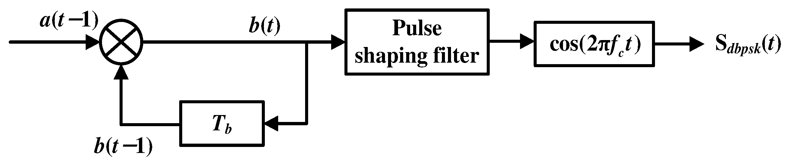
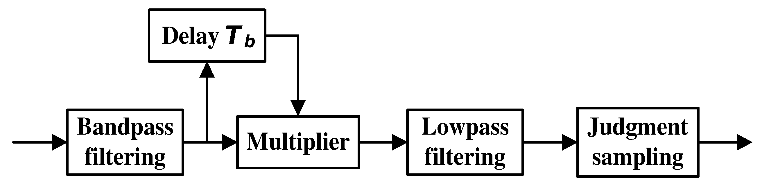
2.1. Basic Principle of DBPSK
2.2. Doppler Estimation and Delay-Tuning Compensation
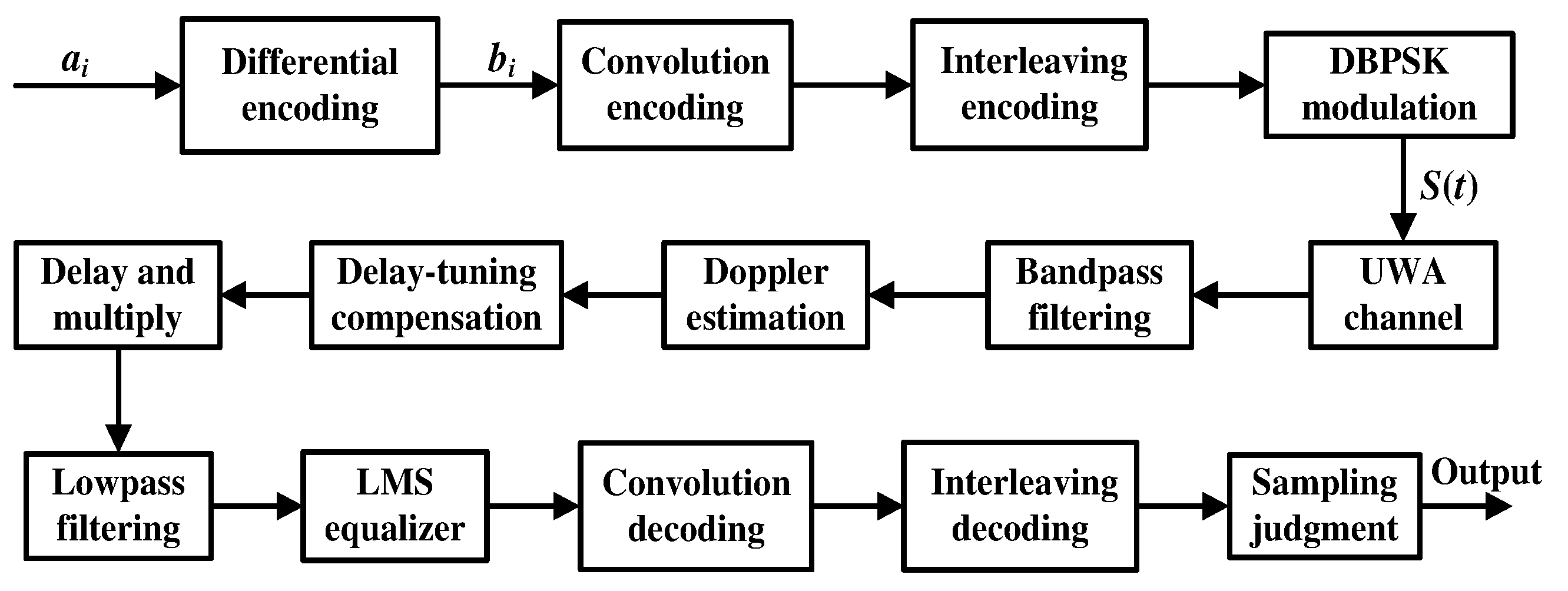
2.3. UWA Communication System
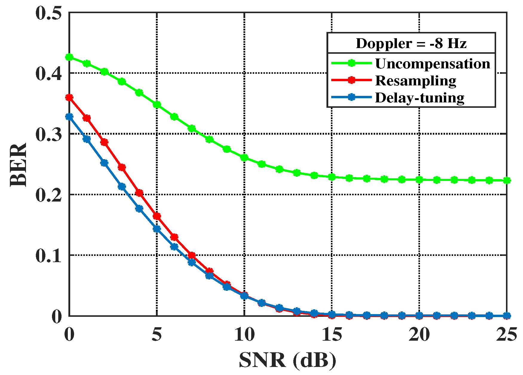
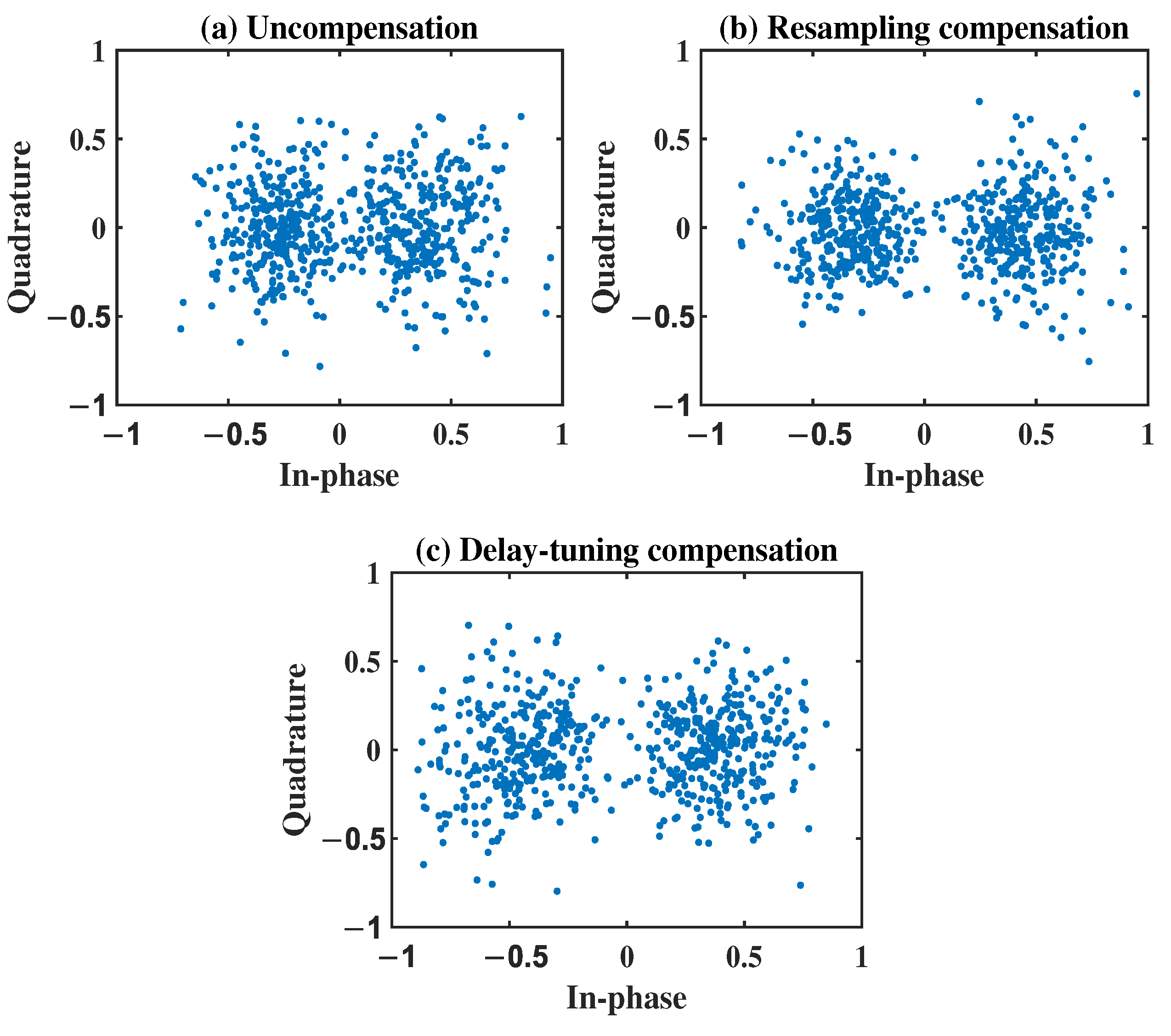
3. Numerical Simulation
4. Experiments and Discussions
4.1. Sea Experiment
4.2. Lake Experiment
5. Conclusions
Author Contributions
Funding
Data Availability Statement
Conflicts of Interest
References
- Li, J.; Bai, Y.; Zhang, Y.; Qu, F.; Wei, Y.; Wang, J. Cross power spectral density based beamforming for underwater acoustic communications. Ocean Eng. 2020, 216, 107786. [Google Scholar] [CrossRef]
- Huang, J.; Diamant, R. Adaptive Modulation for Long-Range Underwater Acoustic Communication. IEEE Trans. Wirel. Commun. 2020, 19, 6844–6857. [Google Scholar] [CrossRef]
- Wu, F.Y.; Yang, K.; Duan, R. Compressed Sensing of Underwater Acoustic Signals via Structured Approximation l0-Norm. IEEE Trans. Veh. Technol. 2018, 67, 8504–8513. [Google Scholar] [CrossRef]
- Zhang, D.; N’Doye, I.; Ballal, T.; Al-Naffouri, T.Y.; Alouini, M.S.; Laleg-Kirati, T.M. Localization and Tracking Control Using Hybrid Acoustic–Optical Communication for Autonomous Underwater Vehicles. IEEE Internet Things J. 2020, 7, 10048–10060. [Google Scholar] [CrossRef]
- Han, X.; Yin, J.; Tian, Y.; Sheng, X. Underwater acoustic communication to an unmanned underwater vehicle with a compact vector sensor array. Ocean Eng. 2019, 184, 85–90. [Google Scholar] [CrossRef]
- Duecker, D.A.; Steinmetz, F.; Kreuzer, E.; Renner, C. Micro AUV Localization for Agile Navigation with Low-cost Acoustic Modems. In Proceedings of the 2020 IEEE/OES Autonomous Underwater Vehicles Symposium (AUV) (50043), St. Johns, NL, Canada, 30 September–2 October 2020; pp. 1–7. [Google Scholar]
- Eldred, R.; Lussier, J.; Pollman, A. Design and Testing of a Spherical Autonomous Underwater Vehicle for Shipwreck Interior Exploration. J. Mar. Sci. Eng. 2021, 9, 320. [Google Scholar] [CrossRef]
- Tao, Q.y.; Zhou, Y.h.; Tong, F.; Song, A.j.; Zhang, F. Evaluating acousticcommunication performance of micro autonomous underwater vehicles in confined spaces. Front. Inf. Technol. Electron. Eng. 2018, 19, 1013–1023. [Google Scholar] [CrossRef]
- Cao, X.L.; Jiang, W.H.; Tong, F. Time reversal mfsk acoustic communication in underwater channel with large multipath spread. Ocean Eng. 2018, 152, 203–209. [Google Scholar] [CrossRef]
- Stojanovic, M. Recent advances in high-speed underwater acoustic communications. IEEE J. Ocean. Eng. 1996, 21, 125–136. [Google Scholar] [CrossRef]
- He, C.; Zhang, Q.; Yan, Z.; Li, Q.; Zhang, L.; Chen, J.; Qi, Q. Experimental demonstration of phase-coherent underwater acoustic communications using a compact array. Ocean Eng. 2017, 145, 207–214. [Google Scholar] [CrossRef]
- Stojanovic, M. An adaptive algorithm for differentially coherent detection in the presence of intersymbol interference. IEEE J. Sel. Areas Commun. 2005, 23, 1884–1890. [Google Scholar] [CrossRef] [Green Version]
- Li, B.; Zheng, S.; Tong, F. Bit-error rate based Doppler estimation for shallow water acoustic OFDM communication. Ocean Eng. 2019, 182, 203–210. [Google Scholar] [CrossRef]
- Han, J.; Chepuri, S.P.; Leus, G. Joint channel and Doppler estimation for OSDM underwater acoustic communications. Signal Process. 2020, 170, 107446. [Google Scholar] [CrossRef]
- Stojanovic, M. Underwater acoustic communication. In Wiley Encyclopedia of Electrical and Electronics Engineering; John Wiley & Sons, Inc.: New York, NY, USA, 1999; pp. 1–12. [Google Scholar]
- Qu, F.; Wang, Z.; Yang, L.; Wu, Z. A journey toward modeling and resolving doppler in underwater acoustic communications. IEEE Commun. Mag. 2016, 54, 49–55. [Google Scholar] [CrossRef]
- Li, B.; Zhou, S.; Stojanovic, M.; Freitag, L.; Willett, P. Multicarrier communication over underwater acoustic channels with nonuniform Doppler shifts. IEEE J. Ocean. Eng. 2008, 33, 198–209. [Google Scholar]
- Sharif, B.S.; Neasham, J.; Hinton, O.R.; Adams, A.E. A computationally efficient Doppler compensation system for underwater acoustic communications. IEEE J. Ocean. Eng. 2000, 25, 52–61. [Google Scholar] [CrossRef]
- Pelekanakis, K.; Chitre, M. Comparison of sparse adaptive filters for underwater acoustic channel equalization/estimation. In Proceedings of the 2010 IEEE International Conference on Communication Systems, Singapore, 17–19 November 2010; pp. 395–399. [Google Scholar]
- Zheng, Y.; Hao, X.; Yan, X. New least mean square algorithm with variable step based on underwater acoustic communication. J. Comput. Appl. 2017, 37, 2195–2199. [Google Scholar]
- Sun, D.; Hong, X.; Cui, H.; Liu, L. Iterative multi-channel FH-MFSK reception in mobile shallow underwater acoustic channels. IET Commun. 2020, 14, 838–845. [Google Scholar] [CrossRef]
- Tao, Y.; Zhu, P.B.; Xu, X.m. Dual-mode modulation based research of underwater acoustic modem. In Proceedings of the 2010 6th International Conference on Wireless Communications Networking and Mobile Computing (WiCOM), Chengdu, China, 23–25 September 2010; pp. 1–3. [Google Scholar]
- Roy, S.; Duman, T.M.; McDonald, V.; Proakis, J.G. High-rate communication for underwater acoustic channels using multiple transmitters and space–time coding: Receiver structures and experimental results. IEEE J. Ocean. Eng. 2007, 32, 663–688. [Google Scholar] [CrossRef]
- Yan, D.; Wang, F.; Wang, S. Research on the output bit error rate of 2DPSK signal based on stochastic resonance theory. Mod. Phys. Lett. B 2017, 31, 1850069. [Google Scholar] [CrossRef] [Green Version]
- Wang, K.; Chen, S.; Liu, C.; Liu, Y.; Xu, Y. Doppler estimation and timing synchronization of underwater acoustic communication based on hyperbolic frequency modulation signal. In Proceedings of the 2015 IEEE 12th International Conference on Networking, Sensing and Control, Taipei, Taiwan, 9–11 April 2015; pp. 75–80. [Google Scholar]
- Li, B.; Tong, F.; Zheng, S.; Chen, D. Bit-error rate gradient descent Doppler estimation for underwater acoustic OFDM communication. Appl. Acoust. 2021, 171, 107557. [Google Scholar] [CrossRef]
- Wang, X.; Zheng, S.; Tao, Q.; Zhang, F.; Song, A.; Tong, F. Doppler correction of mobile acoustic communication via adjustable AD sampling rate. In Proceedings of the Thirteenth ACM International Conference on Underwater Networks & Systems, Shenzhen, China, 3–5 December 2018; pp. 1–5. [Google Scholar]
- Stamatiou, K.; Casari, P.; Zorzi, M. The throughput of underwater networks: Analysis and validation using a ray tracing simulator. IEEE Trans. Wirel. Commun. 2013, 12, 1108–1117. [Google Scholar] [CrossRef]
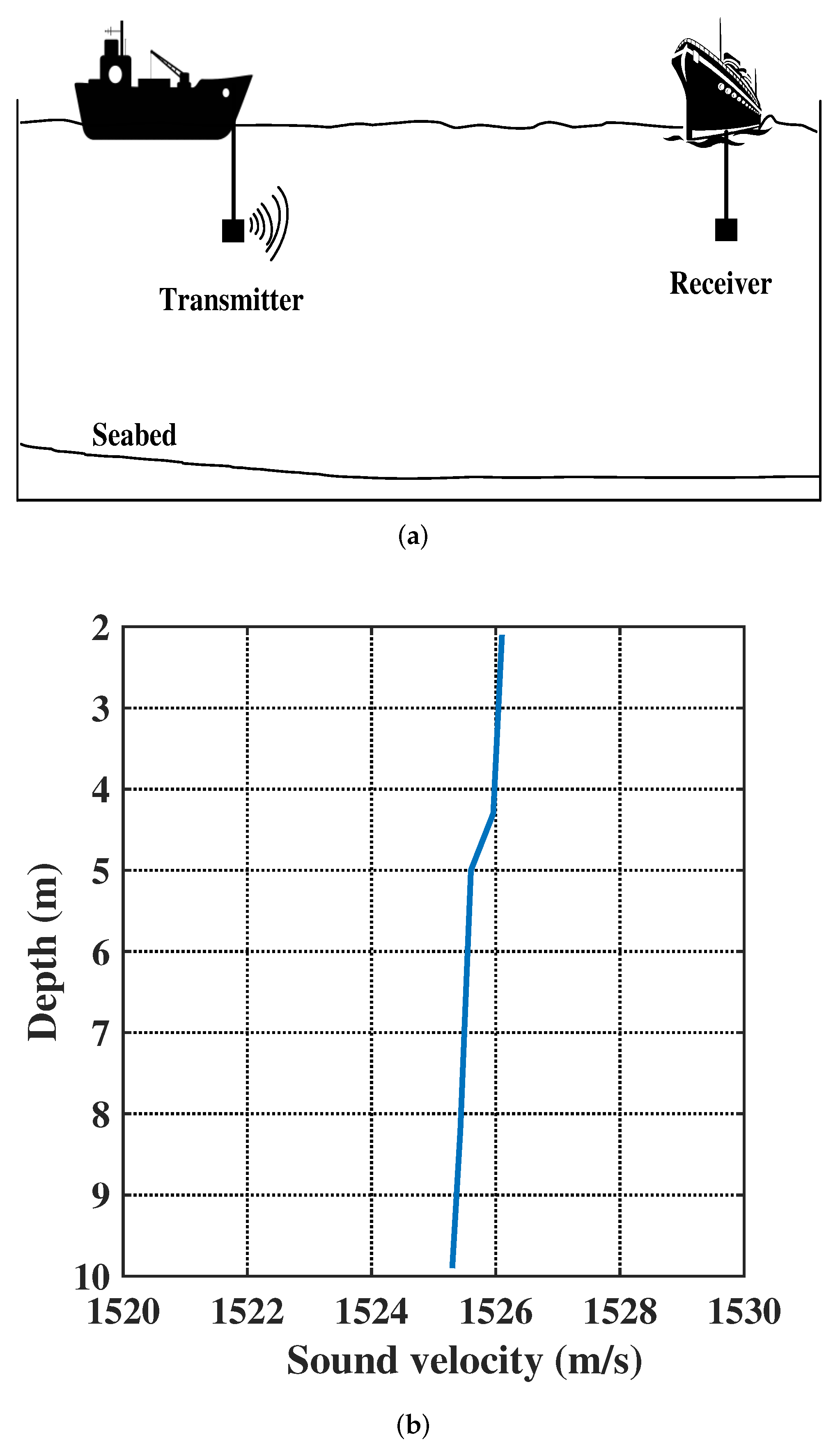
- Frosch, R.A. Underwater Sound: Deep-Ocean Propagation: Variations of temperature and pressure have great influence on the propagation of sound in the ocean. Science 1964, 146, 889–894. [Google Scholar] [CrossRef] [PubMed]
- HY1203 Sound Velocity Profiler. Available online: https://www.haiyingmarine.com/en/index.php?a=lists&catid=10 (accessed on 31 January 2017).
- Li, B.; Tong, F.; Li, J.-H.; Zheng, S.-Y. Cross-correlation quasi-gradient Doppler estimation for underwater acoustic OFDM mobile communications. Appl. Acoust. 2022, 190, 108640. [Google Scholar] [CrossRef]
- Tu, X.; Xu, X.; Song, A. Frequency-Domain Decision Feedback Equalization for Single-Carrier Transmissions in Fast Time-Varying Underwater Acoustic Channels. IEEE J. Ocean. Eng. 2020, 46, 704–716. [Google Scholar] [CrossRef]
- Jiang, W.; Zheng, S.; Zhou, Y.; Tong, F.; Kastner, R. Exploiting time varying sparsity for underwater acoustic communication via dynamic compressed sensing. J. Acoust. Soc. Am. 2018, 143, 3997–4007. [Google Scholar] [CrossRef] [Green Version]


| Description | Value |
|---|---|
| Carrier frequency | 15,500 Hz |
| Sampling frequency | 96,000 Hz |
| Bandwidth | 5000 Hz |
| Data rate | 2000 bps |
| Communication distance | 1000 m |
| Water depth | 40 m |
| SNR | 15 dB |
| Receiver depth | 10 m |
| Transmitter depth | 10 m |
| Doppler | −8 Hz |
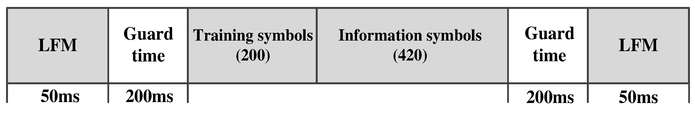
| Known symbols for training | 200 bits |
| Unknown data symbols for recovering | 1800 bits |
| Order of LMS filter | 120 |
| Step factor of LMS equalizer | 0.01 |
| Iteration number | 10,000 |
| Scheme | BER (%) | (dB) | ||
|---|---|---|---|---|
| Uncoded | Coded | Uncoded | Coded | |
| Uncompensation | 12.58 | 15.46 | 5.92 | 3.49 |
| Resampling compensation | 4.19 | 0.10 | 10.68 | 21.40 |
| Delay-tuning compensation | 4.35 | 0.26 | 10.52 | 21.18 |
| Scheme | BER (%) | (dB) | ||
|---|---|---|---|---|
| Unequalization | LMS | Unequalization | LMS | |
| Uncompensation | 20.17 | 15.46 | 1.78 | 3.49 |
| Resampling compensation | 0.23 | 0.10 | 19.95 | 21.40 |
| Delay-tuning compensation | 0.41 | 0.26 | 20.12 | 21.18 |
| Scheme | BER (%) | (dB) | ||
|---|---|---|---|---|
| Uncoded | Coded | Uncoded | Coded | |
| Uncompensation | 11.32 | 0.53 | 4.64 | 11.86 |
| Resampling compensation | 1.37 | 0.08 | 18.09 | 21.58 |
| Delay-tuning compensation | 1.49 | 0.11 | 18.43 | 21.74 |
| Scheme | BER (%) | (dB) | ||
|---|---|---|---|---|
| Unequalization | LMS | Unequalization | LMS | |
| Uncompensation | 9.40 | 0.53 | 5.51 | 11.86 |
| Resampling compensation | 0.17 | 0.08 | 20.29 | 21.58 |
| Delay-tuning compensation | 0.24 | 0.11 | 20.61 | 21.74 |
Publisher’s Note: MDPI stays neutral with regard to jurisdictional claims in published maps and institutional affiliations. |
© 2022 by the authors. Licensee MDPI, Basel, Switzerland. This article is an open access article distributed under the terms and conditions of the Creative Commons Attribution (CC BY) license (https://creativecommons.org/licenses/by/4.0/).
Share and Cite
Jiang, W.; Yang, X.; Tong, F.; Yang, Y.; Zhou, T. A Low-Complexity Underwater Acoustic Coherent Communication System for Small AUV. Remote Sens. 2022, 14, 3405. https://doi.org/10.3390/rs14143405
Jiang W, Yang X, Tong F, Yang Y, Zhou T. A Low-Complexity Underwater Acoustic Coherent Communication System for Small AUV. Remote Sensing. 2022; 14(14):3405. https://doi.org/10.3390/rs14143405
Chicago/Turabian StyleJiang, Weihua, Xiaoyu Yang, Feng Tong, Yijun Yang, and Tianhua Zhou. 2022. "A Low-Complexity Underwater Acoustic Coherent Communication System for Small AUV" Remote Sensing 14, no. 14: 3405. https://doi.org/10.3390/rs14143405