Article

Discrete Element Modeling of Thermally Damaged Sandstone Containing Two Pre-Existing Flaws at High Confining Pressure

1
Anhui Engineering Research Center of Exploitation and Utilization of Closed/Abandoned Mine Resources, Anhui University of Science and Technology, Huainan 232001, China
2
Institute of Energy, Hefei Comprehensive National Science Center, Hefei 230031, China
3
State Key Laboratory for Geomechanics and Deep Underground Engineering, School of Mechanics and Civil Engineering, China University of Mining and Technology, Xuzhou 221116, China
4
Key Laboratory of Rock Mechanics and Geohazards of Zhejiang Province, Shaoxing University, Shaoxing 312099, China
*
Author to whom correspondence should be addressed.
Sustainability 2023, 15(7), 6318; https://doi.org/10.3390/su15076318
Submission received: 25 February 2023 / Revised: 31 March 2023 / Accepted: 4 April 2023 / Published: 6 April 2023
(This article belongs to the Special Issue Sustainable Engineering: Prevention of Rock and Thermal Damage)

Abstract

:
An underground coal gasification (UCG) process is strongly exothermic, which will cause thermal damage on rock cap. We proposed a new thermal damage numerical model based on a two dimension particle flow code (PFC2D) to analyze the inception and extension of cracks on pre-cracked red sandstone, which were thermally treated at a temperature of 25~1000 °C. The results indicated that: (1) a thermal damage value DT obtained by extracting the thermal crack area of scanning electron microscope (SEM), which can be used as an indicator of the degree of thermal damage of the sandstone; (2) a thermal damage numerical model established by replacing the flat-joint model with the smooth-joint model based on the thermal damage value DT, this approach can properly simulate the mechanical behavior and failure patterns of sandstone; (3) the critical temperature for strength reduction was 750 °C. The peak strength increased as pre-treatment temperature increased from 25 to 750 °C and then decreased. The elastic modulus E1 decreased with the increasing thermal treatment temperature; (4) micro-scale cracks initiate from the tip of the prefabricated fissure, and expand along the direction of prefabricated fissure, finally developing into macroscopic fracture. This approach has the potential to enhance the predictive capability of modeling and presents a reliable model to simulate the mechanical behavior of thermally damaged sandstones, thereby offering a sound scientific basis for the utilization of space after UCG.

1. Introduction

Underground coal gasification (UCG) was identified as an environmentally friendly technique for in situ gasification of deep unmineable coal seams, which can expand our energy resources in a sustainable way; additionally, the captured carbon dioxide can be stored in the space after UCG [1,2]. However, the UCG process generates a significant amount of heat, causing temperatures in the burn zone to occasionally exceed 900 °C [3,4], which significantly surpasses the critical point (Tc~400–500 °C) that triggers alterations in the mechanical properties of common sandstones [5]. On the other hand, the mechanical response of rock is more complex when thermal induced cracks combined with pre-existing fissures [6].
Laboratory-scale specimens were extensively used to investigate how temperature affects the properties of rocks [7,8,9,10,11,12,13,14]. These studies mainly focused on physical structure and mechanical response of thermal damaged rock. The temperature ranges from ambient to 400 °C and leads to the evaporation and release of water that is adhered to, combined with, or structurally bound to the sandstone. Between 400 and 600 °C, the minerals in the sandstone undergo thermal reactions and transformation, leading to an increase in porosity, a decrease in permeability and diffusivity, and changes in heat capacity [15]. For red sandstones with pre-existing fissures, the elastic modulus and strength increase at 300 °C but decrease as the temperature rises to 900 °C, while the Poisson’s ratio remains unaffected by temperature changes. As the temperature increases, the crack closure stress, crack initiation stress, and damage threshold first increase and then decrease [5]. In addition, high-temperature damage (HTD) in sandstone induces considerably more acoustic emission (AE) signals [11].
The use of two- or three-dimensional discontinuum models in distinct element methods is a powerful method to simulate various aspects of rock deformation and failure [16,17,18,19], This approach allows for predicting mechanical behavior and tracking fracture evolution under different stress conditions [20]. To account for thermal strain caused by temperature changes, disk radii are adjusted and bond forces are modified accordingly [21]. In order to accurately capture the thermal behavior of rock specimens, different thermal expansion coefficients were assigned to various minerals [22,23]. According to this method, a mesostructured-based numerical model adopted to analyze rock thermal cracking based on elastic damage mechanics and thermal-elastic theory [24,25]. The mechanisms responsible for temperature-dependent mechanical properties of thermal damaged modeling granite [22]. A cluster model in two-dimension particle flow code (PFC2D) was used to simulate a crystalline granite specimen, and crack number variation and crack evolution process was investigated [14]. However, this approach had some shortcomings. Firstly, it is usually applicable to crystalline rocks (such as granite); however, the mineral grains of crystalline rocks are difficult to distinguish. Secondly, the heat temperature should be below 500 °C, because temperatures exceeding this threshold may trigger intricate mineral decomposition and other chemical reactions, such as α-β quartz phase transition, which cannot be accurately simulated by particle mechanics method [22]. In addition, it is difficult to precisely determine the thermal expansion coefficient of different minerals [23].
The mechanical response of fractured rock masses is usually different from that of intact rock masses [26,27,28]. Studies showed that stress concentrations are more likely to occur at the tips of fissures, thus promoting the initiating of new cracks and reducing the strength of the rock mass [29]. Previous studies fully investigated intact rock masses as well as rock masses containing single fissures [30], but rock masses containing two pre-existing fissures, especially the interaction mechanism between fissures and fissures and between fissures and thermal cracks, need further research. Therefore, in this paper, the double-fissure specimens with 45° fissure inclination were subjected to heat treatment at different temperatures in order to determine the influence of thermal damage on the mechanical behavior of fissured red sandstone. Furthermore, we proposed a new approach to establish two-dimension PFC thermal damage numerical model by replacing the flat-joint model with the smooth-joint model according to the thermal damage value DT. The main mechanism of failure and damage of prefabricated fractured sandstone specimens after heat treatment was explored by comparing and analyzing the numerical simulation results and the physical experimental results.

2. Experimental Materials and Procedures

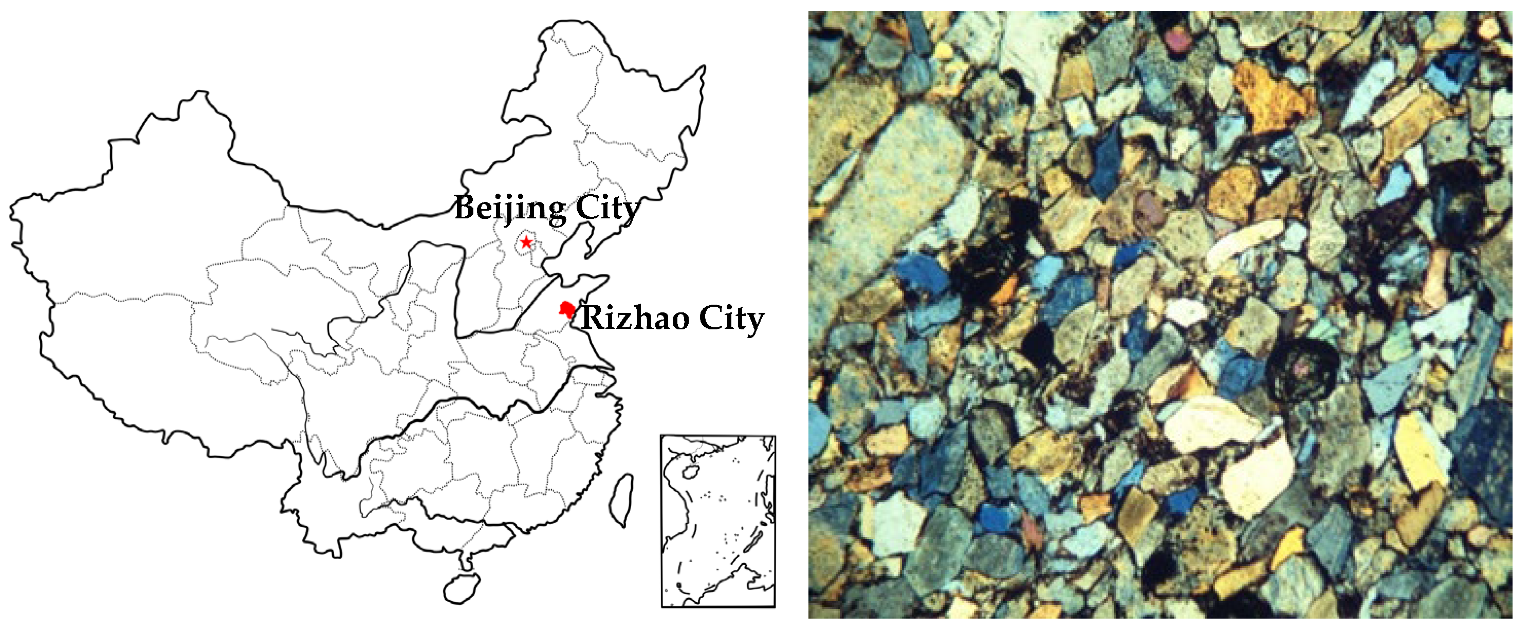
2.1. Preparation for Dual Fissured Sandstone

We used red sandstone from Rizhao City, Shandong Province, China, for our experiments. The sandstone had a dry density of 2402 kg/m3 and an effective porosity of approximately 6.26 to 6.55% [14]. The sandstone was primarily composed of quartz, feldspar, dolomite, hematite, and clay minerals [20] and the microstructure of red sandstone is shown in Figure 1. The samples were cut and polished to form cylinders with diameters of 50 mm and heights of 100 mm in according with ISRM [31]. Subsequently, two nearly identical fissures with lengths (2a = 12 mm) and widths (d = 2 mm) were cut into the samples using a diamond wire saw. The two coplanar fissures had an inclination angle of 45º and were separated by an intervening rock bridge of 2b = 12 mm (Figure 2). The samples were dried for approximately 24 h and were then heated to 250, 500, 750, and 1000 °C at a rate of 5 °C per minute using a high-temperature furnace (Figure 3a), with a sample at room temperature 25 °C serving as the control group. The specimens were held in furnace at their target temperature for two hours before being allowed to cool naturally to room temperature (Figure 3b). The color of the samples changed during the heat treatment process, progressing from a drab-red color at 250 °C to increasingly redder hues at 500 and 750 °C, ultimately becoming brown at 1000 °C (as depicted in Figure 2). This was due to the gradual transformation of iron-containing minerals into hematite as a result of exposure to high temperature [32]. The basic physical parameters of the sandstone specimens are presented in Table 1.

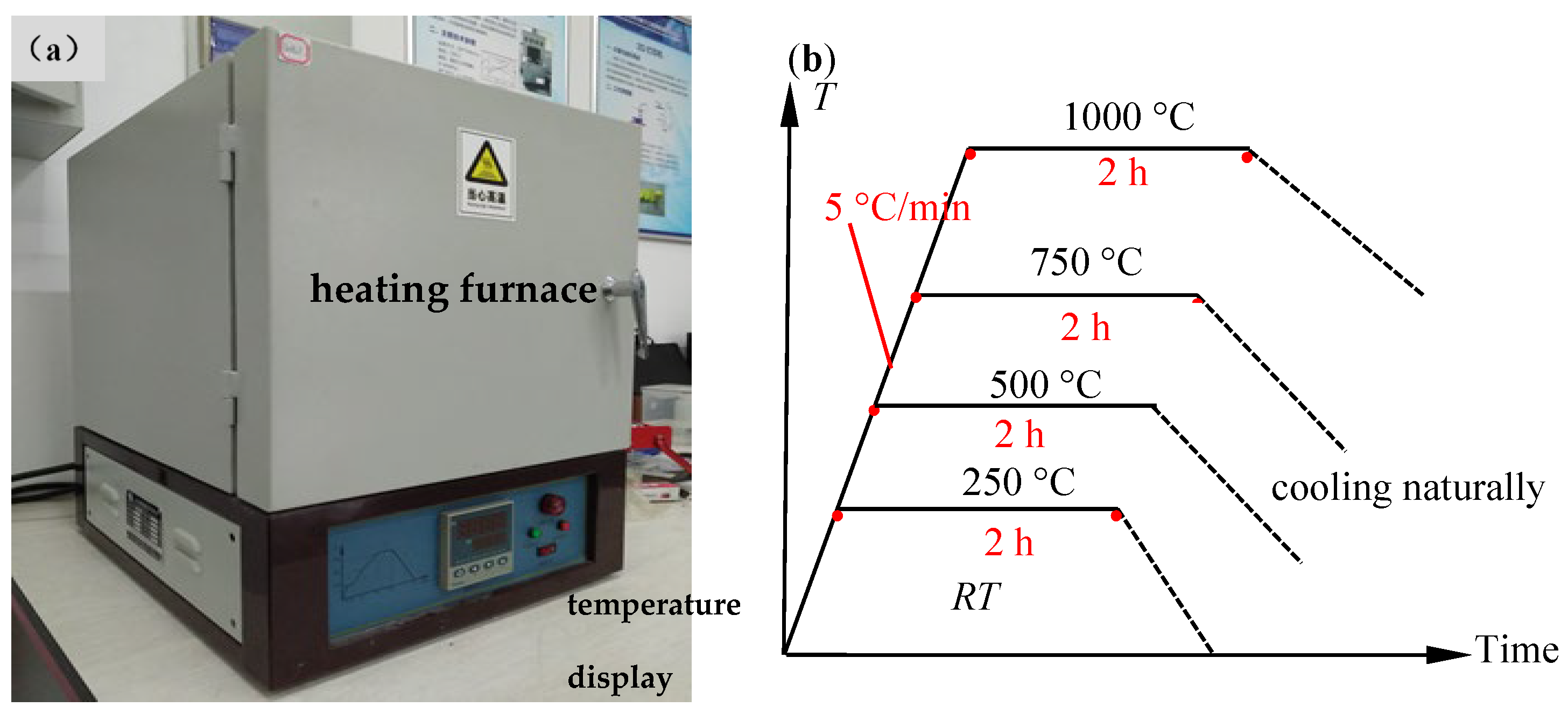
2.2. Experiment Apparatus and Method

To account for the high ground stress experienced during the UCG operation, the confining pressure was set to 30 MPa in triaxial compression experiments. This corresponded to a depth of 1270 m based on the calculated ground stress using the bulk weight (approximately 23.5 kN/m3) of the red sandstone. The conventional triaxial compression experiments were performed using a rock triaxial rheology testing system equipped with three servo-hydraulic control units for applying: axial stress, confining pressure, and pore pressure loads, respectively. The system had a maximum axial loading capacity of 800 kN, and a maximum confining pressure and pore pressure of 60 MPa. The axial deformation of the specimen was monitored using a pair of linear variable displacement transducers (LVDTs), while the circumferential deformation was monitored using a circumferential extensometer.
The testing procedures were as follows: (ⅰ) the samples were subjected to confining pressure of 30 MPa at a rate of 4 MPa/min; (ⅱ) the samples were subjected to axial loading at a rate of 0.04 mm/min until they reached their residual strength. In this manner, the stress–strain curves and triaxial compressive strengths (TCS) of the samples could be obtained. It should be noted that the specimens used in the test contained two prefabricated fissures, the confining pressure will break the rubber sleeve at the location of the fissure and cause the hydraulic oil to enter the specimens, which will affect the mechanical properties of the specimen. Therefore, before installing the rubber sleeve, a piece of iron was affixed to cover the fissures with hot-melt adhesive to prevent the hydraulic oil breaking the rubber sleeve into the specimen. However, placing the iron piece cover on the fissures caused a slight bulge in the middle of the specimen; to prevent this bulge, the circumferential displacement sensor can only be installed in the lower and middle of the specimen, which resulted in a minor lateral deformation being measured.

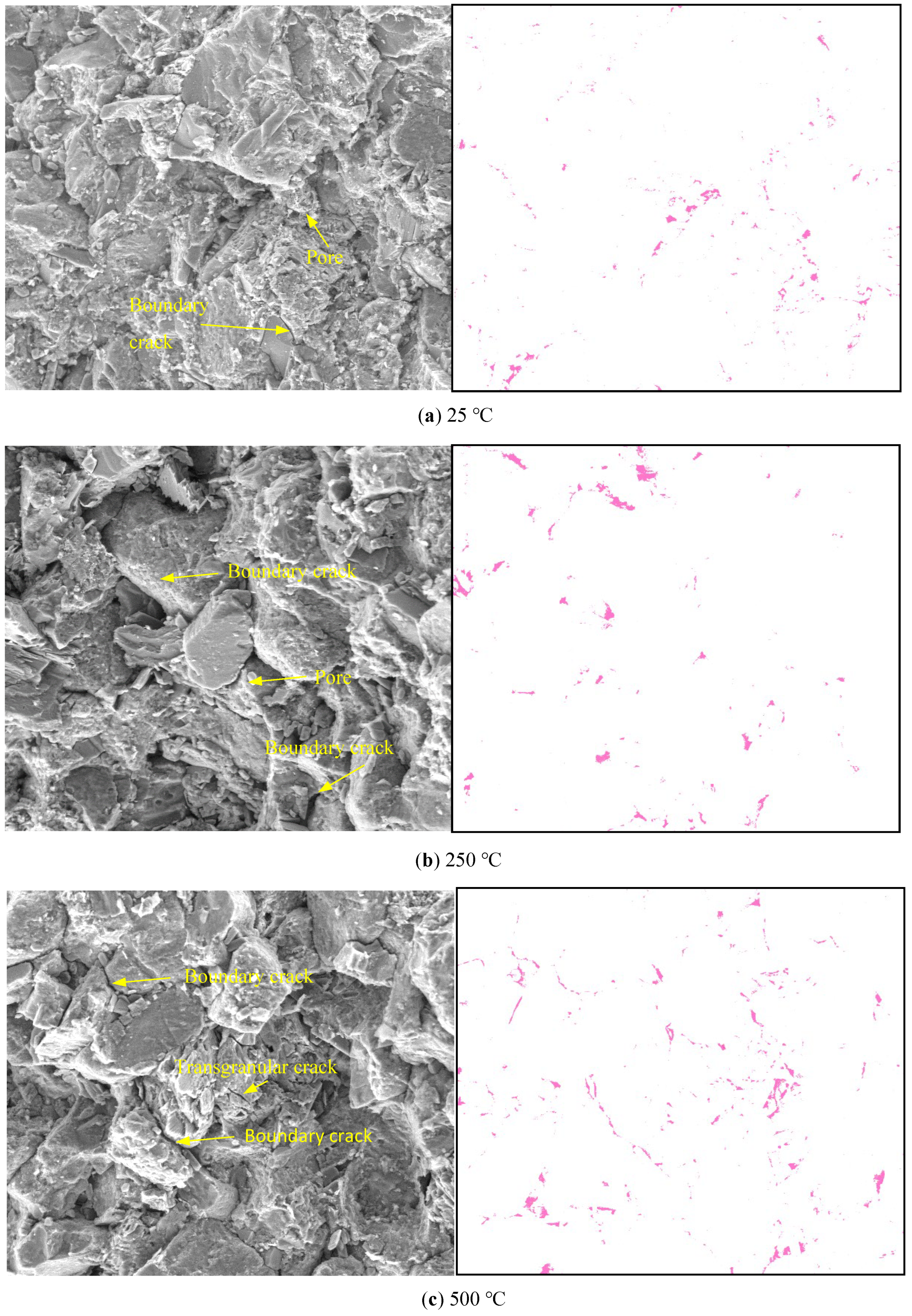
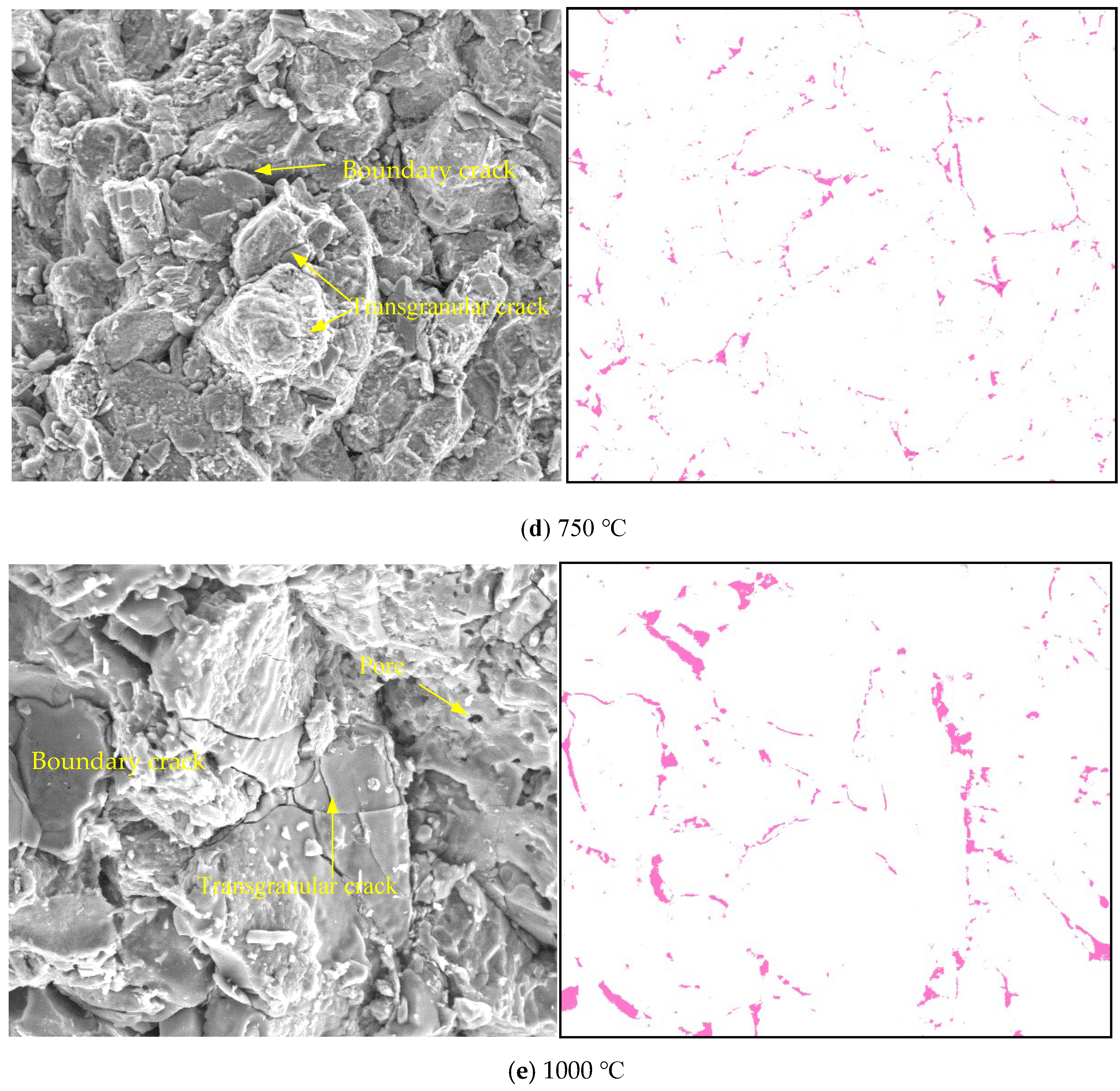
2.3. Thermal Damage Analysis Based on Image Recognition

Scanning electron microscopy (SEM) is usually used for observing the microstructure of rocks, and there are few quantitative studies on the distribution and proportion of micro-cracks, especially micro-cracks caused by heat treatment. Therefore, based on image recognition methods, we extracted micro-cracks from sandstone with different thermal damage in SEM, and conducted a quantitative analysis to determine the influence of heat temperature on thermal cracks distribution. The image threshold segmentation method is a common technical method in the image recognition process, which is simple to operate and implement [34]. The image was composed of two areas with different gray levels, bright and dark, denoted as f (x, y), such as cracks and matrix of rock. The bright and dark parts of this kind of image can be distinguished by the gray value histogram, so a threshold can be selected to distinguish bright and dark peaks. Threshold segmentation can be regarded as a function operation.
T = T x , y , p x , y , f x , y
where x and y is coordinates of pixel, p(x, y) is local features of pixels, f(x, y) is gray value of pixels, the thresholder image is defined as follows:
g x , y = 1 , f x , y > T 0 , f x , y < T
where the pixel grayscale value of 1 corresponds to the target object (cracks), and the pixel grayscale value of 0 corresponds to the background (rock block).
According to this method, the sandstone samples heat-treated at different temperatures were scanned by electron microscope at a magnification of 500 times. Then, a histogram was applied thresholding to the SEM images based to their grayscale value. Finally, an appropriate gray threshold was set to identify and extract the crack area. Due to the gray scale difference between the cracks and the skeleton in the SEM image of rock, according to the visual inspection of the histogram, the gray threshold of the cracks was set to 40~60, and then, the cracks were identified and extracted, as shown in Figure 4 (red area).
SEM images and extracted crack results of the red sandstone after different pre-treatment temperatures are illustrated in Figure 4. In the SEM images of pre-treatment of 25 °C and 250 °C, the grain boundaries and micro voids were clearly visible, and some boundary cracks could also be observed (Figure 4a,b). From 500 °C, the mineral particles inside the rock began to expand due to thermal expansion (Figure 4c). Different mineral particles have different thermal expansion properties, which leads to the dislocation cracks produced [6]. The thermal decomposition of calcite results in the formation of certain transgranular cracks (Figure 4d), especially when the heat treatment temperature continues to increase to 1000 °C, a large number of transgranular cracks and boundary cracks appeared (Figure 4e), which indicated that the thermal damage increased significantly. Furthermore, according to the number of pixels of the identified cracks, the crack areas under different pre-treatment temperature can be calculated; they were 1486 mm2, 1611 mm2, 2338 mm2, 3114 mm2, and 4507 mm2, respectively. The sample without thermal treatment (room temperature) is considered a comparative sample and has no thermal damage, its crack area is regarded as the baseline crack area of the sandstone. For thermal treatment samples, the thermal crack area can be obtained by the total crack area subtracting the original crack area. The damage value DT can be calculated by dividing the thermal crack area by the SEM image area, as shown in the following:
D T = S T S S
where ST represents the thermal crack area, SS represents the SEM image area, measuring 56,100 mm2 in total. DT can be characterizing the degree of thermal damage of the heat treatment rock samples.
The DT values for varying treatment temperatures are calculated according to Equation (3), which correspond to 0%, 0.22%, 1.52%, 2.90%, and 5.39%, respectively. Figure 5 shows the relationship between DT and E against heat treatment temperature (the elastic modulus E presented in Yang et al. 2021). As the temperature increases, the thermal damage value DT gradually increases, and resulting in a decrease in the elastic modulus E. This provides further evidence that the thermal cracks caused the rock sample to become softened.

3. Modeling Method

3.1. Particle Flow Code

The mineral properties, structures, deformation, and strength parameters of rock are sensitive to high temperature treatment. The triaxial compressive strength showed an increase as the temperature was raised from 250 to 750 °C, but experienced a significant decrease once the temperature reached 1000 °C. The main reason for this phenomenon was attributed to the vaporization and escape of the adhered water, combined water and structural water, which occurs between the temperatures of 250 and 750 °C. As a result, this leads to an increase in the coefficient of internal friction, thereby increasing the strength of the rock specimen [5]. When the temperature reaches 1000 °C, the progressive accumulation of thermal damage leads to the development of both boundary and transgranular cracks, in addition to the widening of intergranular cracks; consequently, this contributes to a subsequent reduction in strength [14]. It is difficult to simulate the aforementioned complex mechanical behaviour of rock. The PFC software is a discontinuum programs to simulate rock mechanical behavior by employing the distinct element method [17]. In this study, we used two-dimension PFC numerical mode to reproduce the laboratory triaxial compression experiment on heat treatment sandstone specimen. The flat-joint model was adopted to bond the non-uniform-sized circular particles, because this model can represent the mechanical behavior of rock and obtained reasonable ratio of direct-tension strength to unconfined-compressive strength than the linear parallel bond model [35]. The smooth-joint contact model can convert the rotation between particles on two sides of the joint into relative sliding (Figure 6) [36]; hence, the smooth-joint contact model was employed to replace the flat-joint model bonds proportionally according to DT value, in order to simulate the micro thermally induced cracks.

3.2. Set-Up of Thermal Damage Numerical Model

First, circular particles with a radius of 0.3~0.498 mm were randomly distributed in a 50 × 100 mm square area, which produced an intact sample with a porosity of 6.4% and a density of 2400 kg·m−3. To improve the calculation efficiency and minimize the influence of floating particles, a function was compiled to identify and delete particles with fewer than two contact bonds. Next, particles within a designated area were removed to create numerical samples of pre-cracked sandstone with an inclination angle of 45°. The pre-existing fissure had a length of 12 mm and a width of 2 mm, and the length of the rock bridge was 12 mm, identical to the sandstone specimen used in laboratory testing. The final numerical sample contained 8820 particles with 23,756 flat-joint contact bonds. Finally, the flat-joint bonds were randomly and proportionally replaced with smooth-joint bonds according to the thermal damage value DT to simulate the thermal cracking, resulting in the numerical thermal damage sample shown in Figure 7 (smooth-joint bonds are shown in blue).

3.3. Calibrating Micro-Mechanical Parameters

In the process of parameter calibration, the numerical simulation results were compared with the experimental results, and then, the micro parameters were gradually adjusted to make the simulation results approach the laboratory test results; this process is called trial and error matching. Previous studies determined the correlation between the macro- and micro-parameters; for example, fj_ten and fj_coh mainly affect strength, emod has a linear relationship with elastic modulus, krat affects lateral deformation, and fj_fric affects the ductility and brittleness of post-peak failure [37].
When calibrating the micro-parameters of the numerical simulation for thermal treatment samples, two aspects need to be considered. Firstly, the strengthening effect on the sample strength after undergoing thermal treatment. The laboratory results showed that the strength increased linearly with the increase in treatment temperature in the range of 25~750 °C. The previous studies indicated that the parameter fj_coh in the flat-joint model has a linear relationship with the strength of the rock. Therefore, we fixed other parameters and increased fj_coh accordingly to obtain results that were consistent with the strengthening effect of heat treatment (25~750 °C) on mechanical properties. Secondly, when the heat treatment exceeded 750 °C and reached 1000 °C, there was a significant drop in rock strength. The decrease in strength was not solely caused by the increase in thermal cracking. We also assumeed that the cohesion will decrease. Therefore, we set the cohesion to be the same as at 250 °C. Additionally, to simulate thermal cracks, we used the smooth-joint model, which randomly and proportionally replaced the flat-joint model based on the thermal damage value DT. We calibrated the micro-properties of the smooth joint model in the numerical model against the laboratory experiments results. Using this method, the micro-scale-parameters of flat-joint model and smooth-joint model in thermal damaged modeling specimens are listed in Table 2 and Table 3, respectively.

3.4. Validation Tests

Before conducting numerical simulation tests, we validated the previously proposed method for simulating thermal cracking and confirmed its effectiveness in simulating thermal damage. Keeping the parameters of the flat-joint model uniform, we set up two sets of numerical tests. The first set consisted of a numerical model containing thermal cracks by replacing a part of the flat-joint model with smooth-joint model based on the thermal damage value DT. The second set consisted of a numerical model without thermal cracks. The compression results of the two groups of tests are presented in Figure 8. The numerical specimen without thermal cracks exhibited an almost linear increase in strength with thermal treatment temperature in the range of 0~750 °C, while the numerical specimen with thermal cracks showed no significant effect on strength at 250 °C due to the small number of thermal cracks. However, as the thermal treatment temperature increased, resulting in a difference in strength between the numerical model without thermal cracks and the one with thermal cracks. The difference in strength was 15, 31, and 37 MPa at thermal treatment temperature of 500 °C, 750 °C, and 1000 °C, respectively. Based on the above analysis, we concluded that the smooth-joint model replaced the flat-joint contact model, enabling simulation of the phenomenon of increasing thermal damage caused by the rise in thermal treatment temperature.

4. Results and Discussion

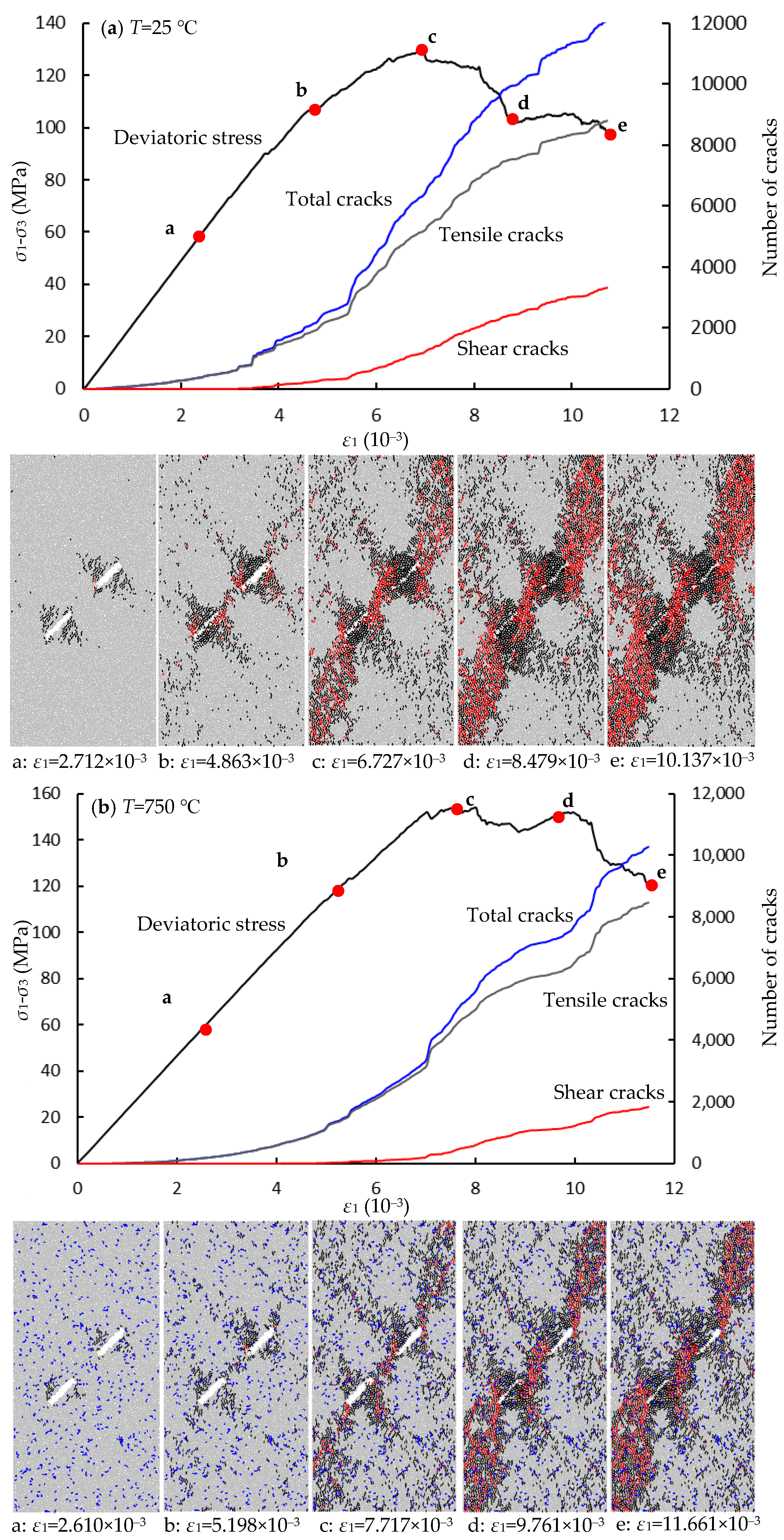
4.1. Mechanical Behavior

Numerical simulations were performed on pre-cracked specimens containing varied number of thermal cracks and calibrated fine-scale parameters. The deviatoric stress–strain curves were compared with the curves obtained from laboratory tests (Figure 9), where the solid line represents the numerical simulation results and the dashed line represents the laboratory tests results. In the initial stage, the dashed line did not exhibit the typical upper concave shape due to the high confining pressure that compressed the initial microcracks in the rock specimen. Thus, linear elastic deformation occurred at the early stage of loading. As the loading continued and approached the first peak strength, the curve growth rate slowed down and transitioned into the plastic deformation stage. A stress drop occurred after reaching the first peak strength due to the closure of the pre-existing cracks, resulting in an increase in the load capacity of the specimen. This closure of prefabricated cracks lead to a second peak strength that was consistently larger than the first peak strength. At a thermal treatment temperature of 1000 °C, after multiple fluctuations near the peak, the experimental curve did not exhibit a significant stress drop (Figure 9e), mainly due to the presence of numerous thermally induced cracks. The gradual closure and expansion of these cracks during compression released some energy, and ultimately, the energy released by the fracture of the pre-existing cracks at the peak was relatively small.
Due to the mechanical properties of the specimen after the first peak strength having a large gap with those before the peak strength, it was unrealistic to simulate two different mechanical behaviors with the same set of fine-scale parameters. Therefore, this study mainly focused on simulating the mechanical properties of the rock at the first peak strength. The simulated curve basically overlaps with the laboratory test curves in the range of 0~500 °C for both deviatoric stress-axial strain curves and the deviatoric stress-lateral strain curves (Figure 9a–c). However, the deviatoric stress-axial strain curves obtained from simulations at thermal treatment temperatures of 750 °C and 1000 °C lie above the laboratory test curves (Figure 9d,e), indicating a higher elastic modulus than that obtained from laboratory tests.
We conducted a further investigation on how thermal treatment temperature affects the elastic moudulus and peak deviatoric stress, as shown in Figure 10. Before reaching 750 °C, there was only a small difference (about 1~2 GPa) between the elastic modulus of physical experiment and numerical simulations. However, this difference increased significantly to 9 GPa at the 1000 °C. Although both physical experiments and numerical simulations showed a decrease in elastic modulus with an increase in thermal treatment temperature, the reduction in numerical simulation after 750 °C was smaller than that in the physical experiment, especially at 1000 °C (Figure 10a). The main reason for this difference is that the physical specimen produced many thermal cracks after high temperature thermal treatment, which closed during the compression process. However, the numerical simulation, where the flat-joint contact was replaced by smooth- joint contact, did not produce any gap, resulting in a smaller elastic modulus than that observed in the physical experiments after 750 °C. Peak deviatoric stress in the numerical experiment was similar to that in the physical experiment at the same temperature (Figure 10b). Both of them increased as the thermal treatment temperature increased from 250 to 750 °C and then, decreased substantially as temperatures reached 1000 °C. These results demonstrate that our proposed thermal damage numerical model can properly simulate the mechanical behavior of sandstone specimens after thermal treatment.

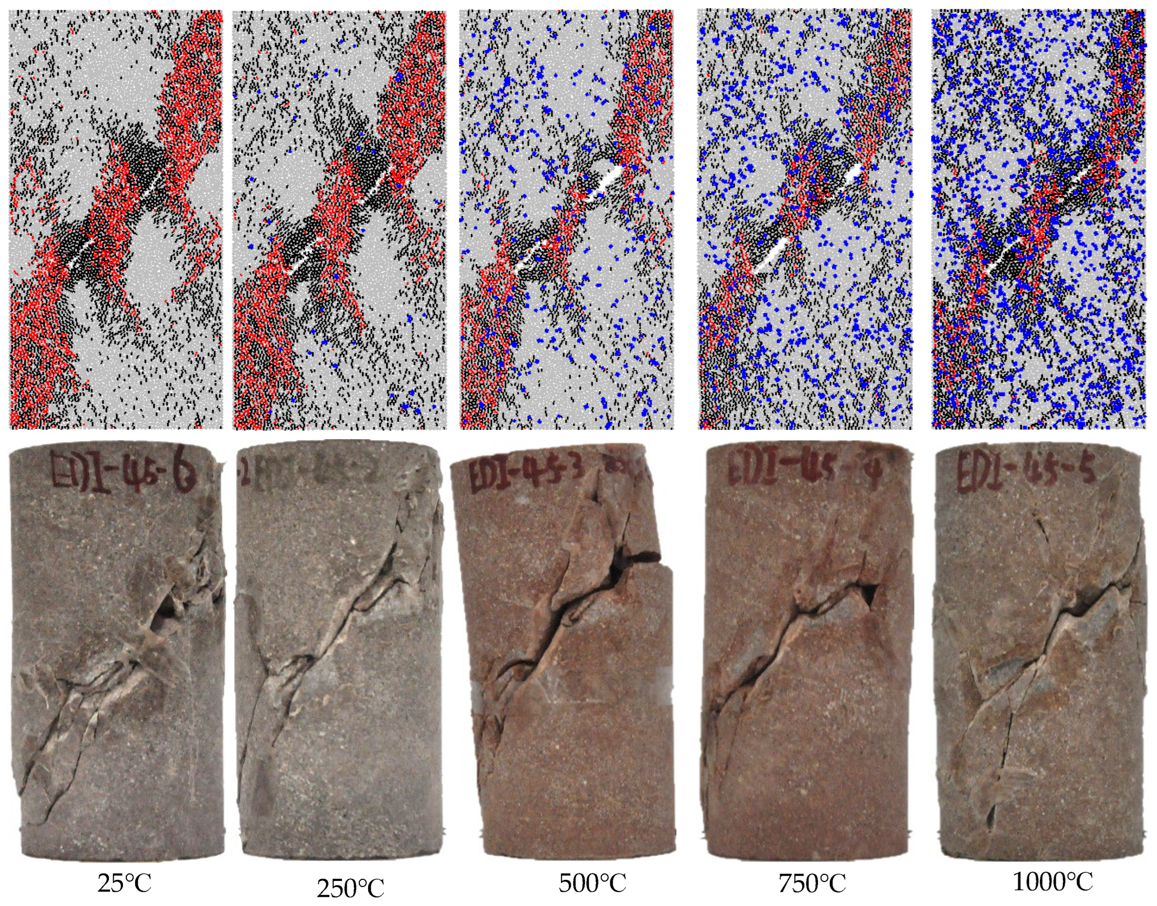
4.2. Failure Pattern

We also analyzed the damage patterns of numerical specimens subjected to different thermal treatment temperatures from a microscopic perspective and compared them with the physical specimens, as shown in Figure 11. In the numerical specimens, the black micro-cracks represented tensile cracks, while the red micro-cracks represented shear cracks. These micro-cracks gathered, expanded, and gradually formed macro-cracks. Macroscopic shear crack bands were produced at each end of the two prefabricated fissures, and the combination of macroscopic shear cracks and prefabricated fissures formed a crack band through the upper and lower ends of the specimen, similar to the damage pattern observed in the physical specimen. A large number of tensile cracks gathered on two sides of the prefabricated fissures, indicating that the prefabricated fissures were mainly dominated by tensile damage. As the thermal treatment temperature increased, the number of microcracks gradually decreased, and the width of the macroscopic shear fracture tended to narrow. The damage patterns of numerical simulations were in good agreement with results of the physical experiment.
Figure 12 shows the displacement of particles in ultimate failure numerical modeling; the displacement of the particles was essentially similar and the particles located on two sides of the pre-existing fissures experienced the largest displacement due to the compression-induced closure. Following these particles, those particles located at the upper and lower ends of the specimen experienced some displacement as well, while the particle at the ends of the prefabricated fracture (indicated by the blue arrow) underwent minimal displacement. Overall, the particles experienced relative displacement along the prefabricated fissure direction. At the outer end of the prefabricated fissures, the direction of displacement changed from parallel to fissure to toward the free surface, which caused surface spalling in physical specimens. On the other hand, at the two sides of the prefabricated fissures, the displacement direction shifted from being parallel to the fissure to vertical orientation, exhibiting a closure of fissure.

4.3. Crack Evolution

There were small differences in damage patterns of specimens due to consistent location, number, and inclination angle of prefabricated fissures. Hence, we selected the thermal damage numerical specimens at 25°C and 750 °C to illustrate the evolution of deviatoric stress and the number of cracks versus axial strain. We chose five representative points from the deviatoric stress-axial strain curve and presented a microcrack corresponding to each point, as shown in Figure 13. At point a, a small number of tensile cracks appeared at the ends of the prefabricated fissures due to stress concentration. The cracks had a wing-shaped distribution, and the specimen without heat treatment exhibited more tensile cracks than the specimen after being subjected to 750 °C heat treatment. When the axial deviatoric stress reached point b, the number of micro tensile cracks on two sides of prefabricated fissures significantly increased and gradually expanded along the direction of the maximum principal stress, while a small number of micro shear cracks appeared, especially for a specimen that was not heat treated. From point b onward, the number of micro tensile cracks increased significantly, and the number of micro shear cracks increased gradually; both specimens exhibited this phenomenon. At point c, the axial deviatoric stress reached its peak, and macroscopic shear cracks formed and connected the two pre-existing cracks. At the outboard of the pre-existing cracks, the shear cracks extended to the upper and lower ends of the specimen. With the increase in axial deviatoric stress to d and e, the shape of macroscopic cracks was basically fixed, but the width of macroscopic cracks gradually increased with the increase microcracks. It should be noted that the specimen without thermal treatment exhibited more microcracks than the specimens after being subjected to 750 °C thermal treatment, and these extra cracks were mainly shear cracks.

5. Conclusions

We proposed a numerical model to simulate the mechanical behavior of thermal damaged rock, based on a series of physical experiments and 2D granular mechanics simulations on pre-cracked sandstone specimens subjected to different temperature thermal treatments. By comparing the results of the numerical and physical experiments, we were able to define the mechanisms of crack evolution at fine scale. The main conclusions of this study are as follows:
(1)
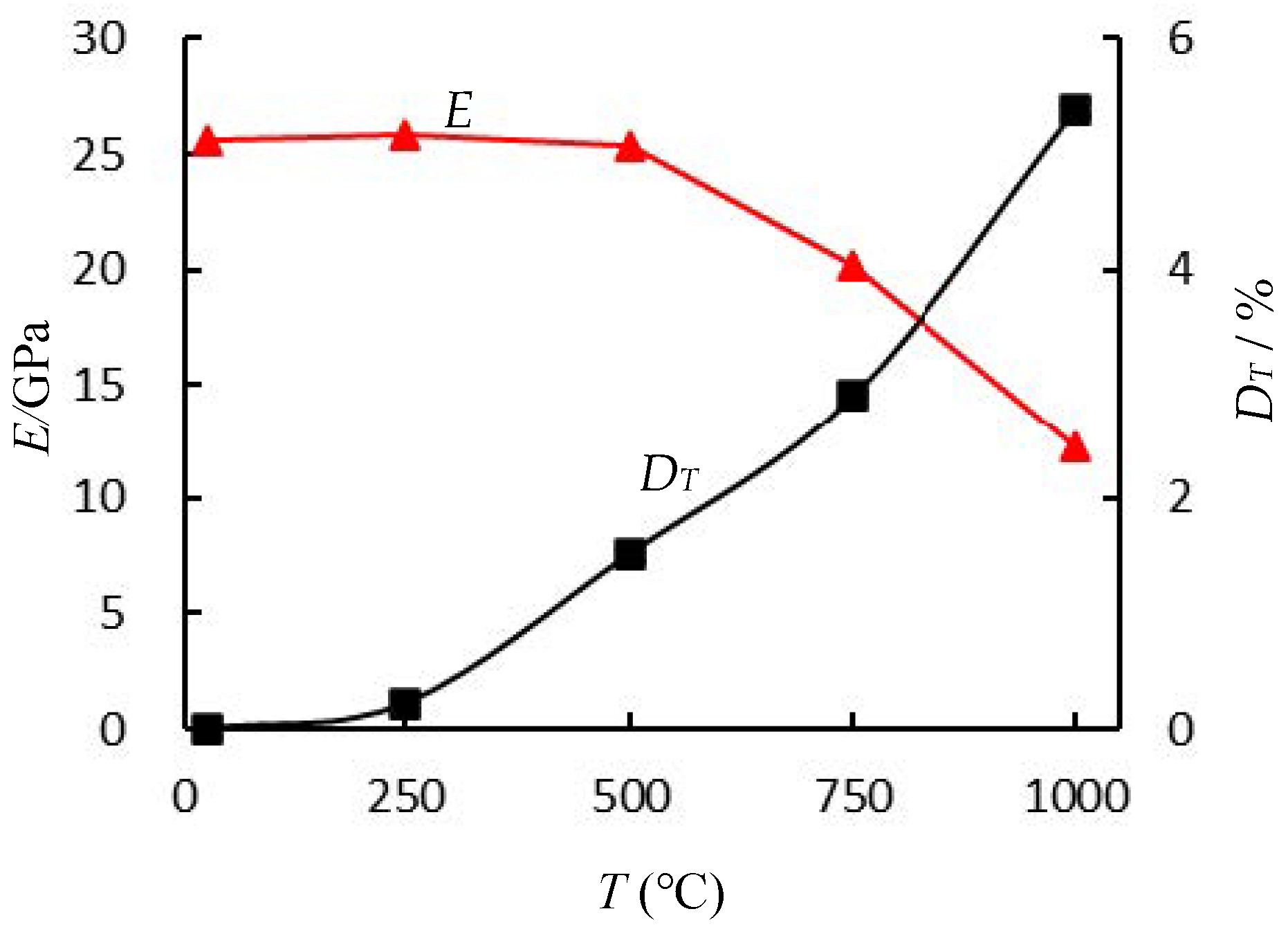
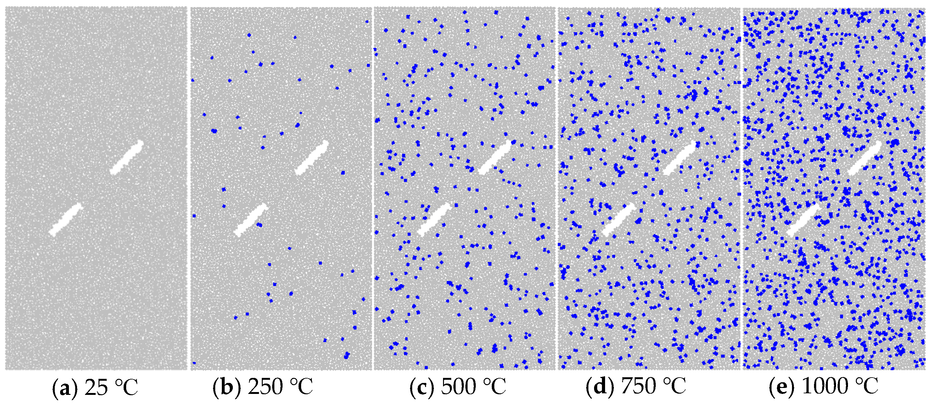
Based on the SEM of the rock samples after thermal treatment at different temperatures, the thermal damage value DT, obtained by extracting the thermal crack area, can be used as an indicator of the degree of thermal damage of the sandstone.
(2)
The thermal damage numerical model, established by replacing the flat-joint model with the smooth-joint model according to the thermal damage value DT, can simulate the mechanical behavior and failure patterns of sandstone properly.
(3)
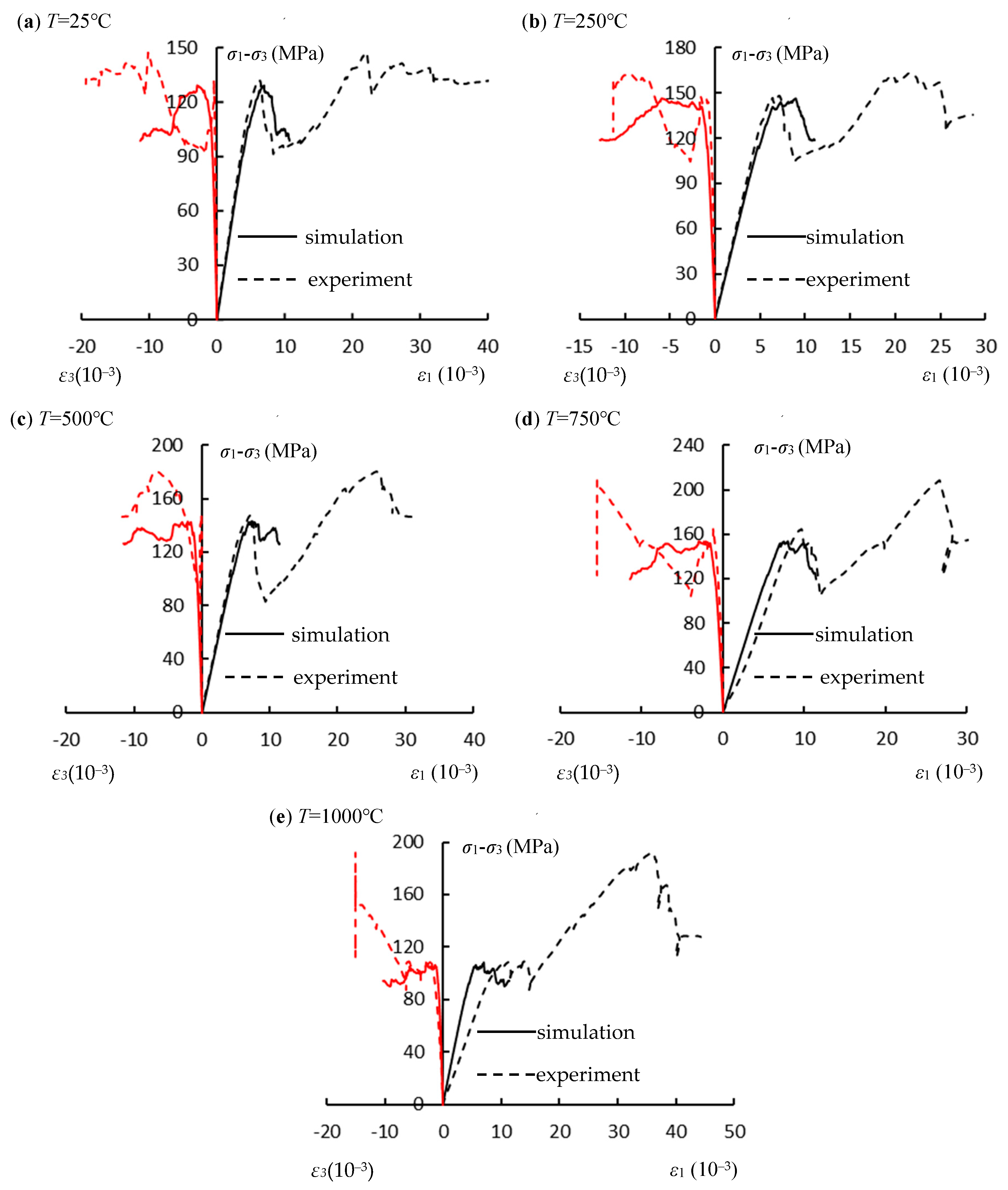
The maximum strength rises with increasing pre-treatment temperature from 25 to 750 °C, but subsequently declines as the pre-treatment temperature approaches 1000 °C. Therefore, the temperature at which the strength begins to decrease significantly is 750 °C, indicating a critical threshold. The elastic modulus E1 decreases with the increasing thermal treatment temperature.
(4)
The evolution of microcracks starts with tensile cracks distributed in a wing shape at the ends of the prefabricated fissures to two sides of the prefabricated fissure, accompanied by a small number of shear cracks, and finally, develops into macroscopic fracture that extend through the entire specimen along the prefabricated fissures. The microcracks of the specimen without thermal treatment more than those of the specimens after 750 °C thermal treatment, and these extra cracks are mainly shear cracks.

Author Contributions

Conceptualization, K.Y.; methodology, G.L.; software, W.T.; validation, M.D.; formal analysis, M.D.; investigation, G.L.; resources, J.T.; data curation, J.T.; writing—original draft preparation, J.T.; writing—review and editing, S.Y.; visualization, J.T.; supervision, S.Y. and K.Y.; project administration, K.Y.; funding acquisition, J.T., S.Y., K.Y. and G.L. All authors have read and agreed to the published version of the manuscript.

Funding

This research was supported by Natural Science Research Project of Anhui Educational Committee (No. 2022AH050811); University-level Key Projects of Anhui University of Science and Technology (13220485); Scientific Research Foundation for High-level Talents of Anhui University of Science and Technology (2021yjrc30); National Natural Science Foundation of China (Grant No. 42077231, 42107177); The Institute of Energy, Hefei Comprehensive National Science Center (Grant No. 21KZS215); Anhui University Collaborative Innovation Project (GXXT-2019-029); The University Natural Science Research Project of Anhui Province (KJ2022A0453); The Key Research and Development Plan of Anhui Province (202104a07020009); The Anhui Engineering Research Center of Exploitation and Utilization of Closed/Abandoned Mine Resources (No. EUCMR202204); and Key Laboratory of Rock Mechanics and Geohazards of Zhejiang Province (No. ZJRMG-2021-01).

Institutional Review Board Statement

Not applicable.

Informed Consent Statement

Not applicable.

Data Availability Statement

Where data is unavailable due to privacy or ethical restrictions.

Conflicts of Interest

The authors declare no conflict of interest.

References

  1. Akbarzadeh, H.; Chalaturnyk, R.J. Structural changes in coal at elevated temperature pertinent to underground coal gasification: A review. Int. J. Coal Geol. 2014, 131, 126–146. [Google Scholar] [CrossRef]
  2. Yang, D.; Koukouzas, N.; Green, M.; Sheng, Y. Recent development on underground coal gasification and subsequent CO2 storage. J. Energy Inst. 2016, 89, 469–484. [Google Scholar] [CrossRef]
  3. Perkins, G. Underground coal gasification-Part I: Field demonstrations and process performance. Prog. Energy Combust. Sci. 2018, 67, 158–187. [Google Scholar] [CrossRef]
  4. Perkins, G. Underground coal gasification-Part II: Fundamental phenomena and modeling. Prog. Energy Combust. Sci. 2018, 67, 234–274. [Google Scholar] [CrossRef]
  5. Yang, S.Q.; Xu, P.; Li, Y.B.; Huang, Y.H. Experimental investigation on triaxial mechanical and permeability behavior of sandstone after exposure to different high temperature treatments. Geothermics 2017, 69, 93–109. [Google Scholar] [CrossRef]
  6. Tian, W.L.; Yang, S.Q.; Elsworth, D.; Wang, J.G.; Li, X.Z. Permeability evolution and crack characteristics in granite under treatment at high temperature. Int. J. Rock Mech. Min. Sci. 2020, 134, 104461. [Google Scholar] [CrossRef]
  7. Chaki, S.; Takarli, M.; Agbodjan, W.P. Influence of thermal damage on physical properties of a granite rock: Porosity, permeability and ultrasonic wave evolutions. Constr. Build. Mater. 2008, 22, 1456–1461. [Google Scholar] [CrossRef]
  8. Tian, H.; Kempka, T.; Xu, N.X.; Ziegler, M. Physical properties of sandstones after high temperature treatment. Rock Mech. Rock Eng. 2012, 45, 1113–1117. [Google Scholar] [CrossRef]
  9. Ranjith, P.G.; Viete, D.R.; Chen, B.J.; Perera, M.S.A. Transformation plasticity and the effect of temperature on the mechanical behaviour of Hawkesbury sandstone at atmospheric pressure. Eng. Geol. 2012, 151, 120–127. [Google Scholar]
  10. Shao, S.; Ranjith, P.G.; Wasantha, P.L.P.; Chen, B.K. Experimental and numerical studies on the mechanics behaviour of Australian Strathbogie granite at high temperatures: An application to geothermal energy. Geothermics 2015, 54, 96–108. [Google Scholar] [CrossRef]
  11. Kong, B.; Wang, E.; Li, Z.; Wang, X.; Liu, X.; Li, N.; Yang, Y. Electromagnetic radiation characteristics and mechanical properties of deformed and fractured sandstone after high temperature treatment. Eng. Geol. 2016, 209, 82–92. [Google Scholar] [CrossRef]
  12. Peng, J.; Rong, G.; Cai, M.; Yao, M.; Zhou, C. Physical and mechanical behaviors of a thermal-damaged coarse marble under uniaxial compression. Eng. Geol. 2016, 200, 88–93. [Google Scholar] [CrossRef]
  13. Fan, L.F.; Gao, J.W.; Wu, Z.J.; Yang, S.Q.; Ma, G.W. An investigation of thermal effects on micro-properties of granite by X-ray CT technique. Appl. Therm. Eng. 2018, 140, 505–519. [Google Scholar] [CrossRef]
  14. Yang, S.Q.; Hu, B. Creep and long-term permeability of a red sandstone subjected to cyclic loading after thermal treatments. Rock Mech. Rock Eng. 2018, 51, 2981–3004. [Google Scholar] [CrossRef]
  15. Sun, Q.; Lü, C.; Cao, L.; Li, W.; Geng, J.; Zhang, W. Thermal properties of sandstone after treatment at high temperature. Int. J. Rock Mech. Min. Sci. 2016, 85, 60–66. [Google Scholar] [CrossRef]
  16. Cundall, P.; Starck, O. A discrete numerical model for granular assemblies. Geotechnique 1979, 29, 47–65. [Google Scholar] [CrossRef]
  17. Potyondy, D.O.; Cundall, P.A. A bonded-particle model for rock. Int. J. Rock Mech. Min. Sci. 2004, 41, 1329–1364. [Google Scholar] [CrossRef]
  18. Potyondy, D.O. The bonded-particle model as a tool for rock mechanics research and application: Current trends and future directions. Geosyst. Eng. 2015, 18, 1–28. [Google Scholar] [CrossRef]
  19. Wang, M.; Lu, Z.; Wan, W.; Zhao, Y. A calibration framework for the microparameters of the DEM model using the improved PSO algorithm. Adv. Powder Technol. 2021, 32, 358–369. [Google Scholar] [CrossRef]
  20. Tang, J.Z.; Yang, S.Q.; Elsworth, D.; Tao, Y. Three-dimensional numerical modeling of grain-scale mechanical behavior of sandstone containing an inclined rough joint. Rock Mech. Rock Eng. 2021, 2, 905–919. [Google Scholar] [CrossRef]
  21. Wanne, T.S.; Young, R.P. Bonded-particle modeling of thermally fractured granite. Int. J. Rock Mech. Min. Sci. 2008, 45, 789–799. [Google Scholar] [CrossRef]
  22. Zhao, Z.H. Thermal influence on mechanical properties of granite: A microcracking perspective. Rock Mech. Rock Eng. 2016, 49, 747–762. [Google Scholar] [CrossRef]
  23. Tian, W.L.; Yang, S.Q.; Huang, Y.H. Macro and micro mechanics behavior of granite after heat treatment by cluster model in particle flow code. Acta Mech. Sin. 2018, 34, 175–186. [Google Scholar] [CrossRef]
  24. Yu, Q.L.; Ranjith, P.G.; Liu, H.Y.; Yang, T.H.; Tang, S.B.; Tang, C.A.; Yang, S.Q. A microstructure-based damage model for thermal cracking analysis and application in granite at elevated temperatures. Rock Mech. Rock Eng. 2015, 48, 2263–2282. [Google Scholar] [CrossRef]
  25. Yang, S.Q.; Tian, W.L.; Huang, Y.H. Failure mechanical behavior of pre-holed granite specimens after elevated temperature treatment by particle flow code. Geothermics 2018, 72, 124–137. [Google Scholar] [CrossRef]
  26. Zhao, Y.; Zhang, L.; Wang, W.; Pu, C.; Wan, W.; Tang, J. Cracking and stress-strain behavior of rock-like material containing two flaws under uniaxial compression. Rock Mech. Rock Eng. 2016, 49, 2665–2687. [Google Scholar] [CrossRef]
  27. Zhao, Y.; Tang, J.; Chen, Y.; Zhang, L.; Wang, W.; Wan, W.; Liao, J. Hydromechanical coupling tests for mechanical and permeability characteristics of fractured limestone in complete stress–strain process. Environ. Earth Sci. 2017, 76, 24. [Google Scholar] [CrossRef]
  28. Tang, J.Z.; Yang, S.Q.; Zhao, Y.L.; Tian, W.L. Experimental and numerical modeling of the shear behavior of filled rough joints. Comput. Geotech. 2020, 121, 103479. [Google Scholar] [CrossRef]
  29. Wang, M.; Wan, W.; Zhao, Y.L. Experimental study on crack propagation and coalescence of rock-like materials with two pre-existing fissures under biaxial compression. Bull. Eng. Geol. Environ. 2020, 79, 3121–3144. [Google Scholar] [CrossRef]
  30. Lee, H.; Jeon, S. An experimental and numerical study of fracture coalescence in pre-cracked specimens under uniaxial compression. Int. J. Solids Struct. 2011, 48, 979–999. [Google Scholar] [CrossRef] [Green Version]
  31. ISRM. The Complete ISRM Suggested Methods for Rock Characterization, Testing and Monitoring; 1974–2006. Suggested Methods Prepared by the Commission on Testing Methods, International Society for Rock Mechanics; Ulusay, R., Hudson, J.A., Eds.; ISRM Turkish National Group: Ankara, Turkey, 2007. [Google Scholar]
  32. Sun, H.; Sun, Q.; Deng, W.; Zhang, W.; Lü, C. Temperature effect on microstructure and p-wave propagation in Linyi sandstone. Appl. Therm. Eng. 2017, 115, 913–922. [Google Scholar] [CrossRef]
  33. Yang, S.Q.; Tang, J.Z.; Elsworth, D. Creep rupture and permeability evolution in high temperature heat-treated sandstone containing pre-existing two flaws. Energies 2021, 14, 6362. [Google Scholar] [CrossRef]
  34. Arena, A.; Piane, C.D.; Sarout, J. A new computational approach to cracks quantification from 2D image analysis: Application to micro-cracks description in rocks. Comput. Geosci. 2014, 66, 106–120. [Google Scholar] [CrossRef]
  35. Potyondy, D.O. A flat-jointed bonded-particle material for hard rock. In Proceedings of the 46th US Rock Mechanics/Geomechanics Symposium, Chicago, IL, USA, 24–27 June 2012. [Google Scholar]
  36. Ivars, D.M.; Potyondy, D.O.; Pierce, M.; Cundall, P.A. The Smooth-Joint Contact Model. In Proceedings of the 8th World Congress on Computational Mechanics and 5th European Congress on Computational Methods in Applied Sciences and Engineering, Venice, Italy, 30 June–5 July 2008. [Google Scholar]
  37. Bahaaddini, M.; Sheikhpourkhani, A.M.; Mansouri, H. Flat-joint model to reproduce the mechanical behaviour of intact rocks. Eur. J. Environ. Civ. Eng. 2021, 25, 1427–1448. [Google Scholar] [CrossRef]
Figure 1. The sampling location and the microstructure of fissured sandstone sample. The figure of microstructure of sandstone adapted with permission from Ref. [14]. 2018, Rock Mech. Rock Eng.
Sustainability 15 06318 g001
Figure 2. Pre-cracked red sandstone specimens after exposure to different temperature [33].
Sustainability 15 06318 g002
Figure 3. High-temperature furnace and heating scheme. (a) High temperature heating furnace. (b) Heating scheme of sandstone specimens.
Sustainability 15 06318 g003
Figure 4. SEM observation results and crack extraction results of different thermally damaged red sandstones (part of the SEM results were drawn from literature [33]).
Sustainability 15 06318 g004aSustainability 15 06318 g004b
Figure 5. Effect of thermal treatment on E and DT.
Sustainability 15 06318 g005
Figure 6. Notation used to define joint and smooth-joint contact [36].
Sustainability 15 06318 g006
Figure 7. Numerical thermal damage specimens.
Sustainability 15 06318 g007
Figure 8. The effects of thermal cracks on the deviatoric stress in simulations.
Sustainability 15 06318 g008
Figure 9. Comparisons of the stress–strain curves in tests and simulations of the fissured red sandstones after different temperature thermal treatment.
Sustainability 15 06318 g009
Figure 10. Comparisons of the elastic modulus and peak deviatoric stress against heat temperature in experiments and simulations. (a) The effects of the temperature on elastic modulus. (b) The effects of the temperature on peak deviatoric stress.
Sustainability 15 06318 g010
Figure 11. Comparisons of the failure pattern for the fissured red sandstones with different thermal temperature treatments.
Sustainability 15 06318 g011
Figure 12. Displacement of particles of the fissured red sandstones with different thermal temperature treatments.
Sustainability 15 06318 g012
Figure 13. The crack evolution of the dual fissured red sandstones after different temperature heat treatments.
Sustainability 15 06318 g013
Table 1. Basic physical parameters and experimental design scheme of fissured red sandstones.
SpecimenDip (°)H (mm)D (mm)M (g)ρ (kg/m3)T (°C)
EDⅠ-45-645100.8149.97481.12433.4825
EDⅠ-45-245101.2250.00473.12380.44250
EDⅠ-45-345101.2550.08481.82351.81500
EDⅠ-45-445100.0950.03477.02301.14750
EDⅠ-45-545101.6650.46481.22225.591000
Table 2. Modeling parameters of Flat-joint model in PFC2D simulation for the specimens.
T (°C)emod (GPa)kratfj_ten (MPa)fj_coh (MPa)fj_fa (°)fj_fric
25232.010.640220.2
250232.010.650220.2
500232.010.660220.2
750232.010.670220.2
1000232.010.650220.2
Table 3. Modeling parameters of the smooth-joint model in PFC2D simulation for the specimens.
T (°C)sj_kn (GPa)sj_ks (GPa)sj_fricsj_ten (MPa)sj_coh (MPa)sj_fa (°)sj_stateNumber of sj
256006000.2141000
2506006000.21410053
5006006000.214100361
7506006000.214100690
10006006000.2141001280
Disclaimer/Publisher’s Note: The statements, opinions and data contained in all publications are solely those of the individual author(s) and contributor(s) and not of MDPI and/or the editor(s). MDPI and/or the editor(s) disclaim responsibility for any injury to people or property resulting from any ideas, methods, instructions or products referred to in the content.

