1. Introduction
When conducting mining operations, the final stage in restoring the economic value of the deposit exploitation area is the reclamation of disturbed lands [
1,
2,
3]. It is a very important process in ecosystem restoration [
4]. The restoration of the primary, natural state of the territory where mining of minerals took place, as well as the presence of green planting, ensures the normal functioning of not only plants but also the animal world, which are important links in the existence of nature [
5,
6]. Such an approach enables sustainable natural resource management to ensure strategic environmental development [
7,
8] as well as mining sustainability, as it meets the needs of individuals, society, and the state in terms of the rational use of natural resources, especially mineral resources [
9].
The largest volume of overburden rocks accumulates during the surface mining of steep-dipping deposits and the exploitation of deep open pits, because such open pits are characterized by thick overburden rocks [
10,
11,
12]. The dangers associated with active and depleted open pits are mainly due to the instability of the rock masses that form their slopes [
13]. The above can lead to sudden landslides and the occurrence of heaving sands. The main causes of landslides are excessive steepness of open-pit slopes and the accumulation of significant volumes of overburden rocks on the surface near the open-pit contours [
14,
15]. The various forms of technogenic cavities formed on the daylight surface reduce the comfort level of the population, disrupt the normal operation of enterprises, and increase the probability of disasters [
16,
17]. Therefore, the solution to the issues related to both the utilization of overburden rocks and the disposal of technogenic cavities is relevant, and the obtained research results are of significant scientific and practical interest.
The analysis of reclamation methods of depleted open pits has shown that the effectiveness of their implementation is closely related to the conditions of occurrence and the thickness of mineral deposits [
18,
19]. Additionally, the direction of the restoration of disturbed lands significantly depends on the place where mining production waste is stockpiled: in the mined-out space or outside its boundaries [
20]. As practice has shown, filling the internal mined-out space of an open pit and its individual sections with overburden rocks is the main measure that contributes to the rational use of the land around the open pit [
3,
21,
22]. The adoption of this technological solution is especially relevant in the conditions in Ukraine when mining open iron-ore pits, the set target depth of which is within 500–705 m [
23]. As many deep open pits are already reaching their target depths, there are increasing concerns about the safe placement of overburden rocks, the timely dumping of which can maintain ore mining capacities and increase the efficiency of mining production [
24]. In studies [
25,
26,
27,
28], researchers have used numerical modeling and simulation techniques to study the internal dump slope stability. Empirical and experimental studies of the internal dump stability are presented in [
29,
30]. Several researchers have proposed and evaluated stability analysis and internal dump design methods [
31,
32,
33]. Important issues include geotechnical characterization and the monitoring of internal dumps to assess their stability [
34,
35,
36]. Overall, these studies provide valuable insights into the various approaches and methods used to assess the stability of internal dumps and highlight the importance of geotechnical characterization, monitoring, and analysis to ensure the safe operation of mining facilities.
Mining operations in deep open pits are performed in stages (in turn), taking into account the position of the working zone for a certain period of time, both in depth and in plan. The identification of stages makes it possible to form internal temporary or permanent dumps in the process of mining operations [
37]. Physical–mechanical, mining–geological and hydrogeological conditions, which are formed within the boundaries of the mined-out space, determine the possibilities of dumping the overburden rocks inside the open pit. Rock dumping with the formation of a solid slope can be directly performed from the surface or with a multitier formation of internal dumps [
38]. The location of internal dumps within the boundaries of an open-pit slope can lead to serious problems related to its stability, because this zone is potentially destructive and can easily deform under the influence of external loading from mining equipment [
39]. The placement of rocks in the mined-out space of a deep open pit, taking into account the technological schemes for the development of mining operations, is based on determining a safety factor for the dump slopes and the safe distance for mining equipment operation [
40,
41]. It is possible to dump overburden rocks in the mined-out space of open pits with the constant stockpiling of overburden rocks in a previously created space of existing open pits, mined-out to the target depth, and to dump overburden rocks in the mined-out space of water-flooded open pits.
The method of internal dumping using controlled rock deformations with a temporary crest of bench in a depleted deep open pit, flooded with groundwater, with steep slope inclination angles has been studied in detail [
42,
43,
44]. The analysis in these studies showed that mass dumped by dragline tends to slide. At the same time, landslide stabilization does not guarantee the safety of dump formation when setting mining equipment on a dumped mass. In some papers [
45,
46,
47], it has been noted that one of the most problematic issues is the determination of the safe distance of the dragline location from the upper slope edge in a single-tier dump formation from soft overburden rocks. At the same time, the reliable prediction of the stability of bench slopes and open-pit slopes enables the development of measures to prevent dangerous deformations [
48,
49].
In geotechnical engineering, slope stability analysis is used to determine the stability of natural and human-made slopes under various conditions. Slope stability is influenced by factors such as rock properties, groundwater, external loads, and slope geometry [
50].
The relationship between the slope sliding surface and the safe distance can be determined using slope stability analysis. In the limit state design, the safe distance is determined based on a safety factor, which is the ratio of the shear strength of the rock to the shear stress acting on the slope’s sliding surface. A higher safety factor indicates a more stable slope, and a lower safety factor indicates a greater risk of slope failure. The safe distance required to ensure a given safety factor depends on several factors, including the rock properties, groundwater conditions, external loads, and the geometry of the slope and adjacent structures. In general, an increase in the safe distance is required as the slope becomes steeper and adjacent structures become more vulnerable to damage.
It is important to note that the safety distance is just one of the factors to consider when assessing slope stability and ensuring safety. Thorough geotechnical studies and analyses are necessary to determine the appropriate safety measures and design parameters for a slope and its surrounding environment [
51,
52].
It is critically important to have a stable slope to prevent dragline failures that may occur during slope collapse. This occurs when a slope fails due to instability, which is usually caused by an inadequate slope angle, poor slope design, or geological factors. Dragline failures can be dangerous and expensive, resulting in loss of life, equipment damage, and production losses. There are many such cases of catastrophic mining engineering accidents around the world [
53,
54,
55,
56].
To date, one of the most effective open-pit reclamation methods is to fill it with waste rocks with the creation of a vegetation layer on its surface. The implementation of this method is especially relevant for deep open pits. As the volume of overburden rocks increases, the need for additional areas for their placement accordingly increases. The height of external multitier dumps can reach 80 m, which negatively affects the geological structures and hydrogeological conditions at the base of these dumps. The height of these dumps may be greater, but then the cost of rock mass delivery increases and the stability of the slopes decreases (as there is a need to reduce the slope angles and the resulting dump angle, requiring additional land area). Consequently, reclamation processes become more expensive. Placing external dumps near open pits completely changes the surface landscape. The majority of external dumps, when mining deep open pits, are not reclaimed for a long period of time. With strong wind currents, solid rock particles are blown off the surface of external dumps and carried considerable distances from the dump location. When stockpiling waste rocks in the internal dump of an open pit, the most problematic issue is to ensure the stability of the dump slope, which determines the safe distance for the dragline location from the upper edge of the slope. This is exactly we aimed at with this study.
Thus, the purpose of this research was to study the stability of internal dump slopes during their formation in the mined-out space of a deep and open iron-ore pit to determine the safe distance from the outer contour of the dragline base to the upper edge of a single-tier dump.
To achieve this purpose, the authors formulated and performed the following scientific and practical tasks:
- −
Based on the mine surveying data on a situational plan for conducting mining operations, we identified the main sections along the entire perimeter of the open pit, located in the zones of maximum fracturing.
- −
On the basis of computer modeling, we substantiated the parameters of the change in the safety factor of the internal dump slopes, depending on the mining–geological conditions of their formation, with further comparison by normative documents.
- −
On the basis of the determined safety factor for the internal dump slopes, we characterized the parameters for the safe distance for the operation of mining equipment along the entire open-pit perimeter.
- −
Based on the obtained results, we proposed a solution for the internal dump formation in the mined-out space of a deep and open iron-ore pit.
2. Study Area
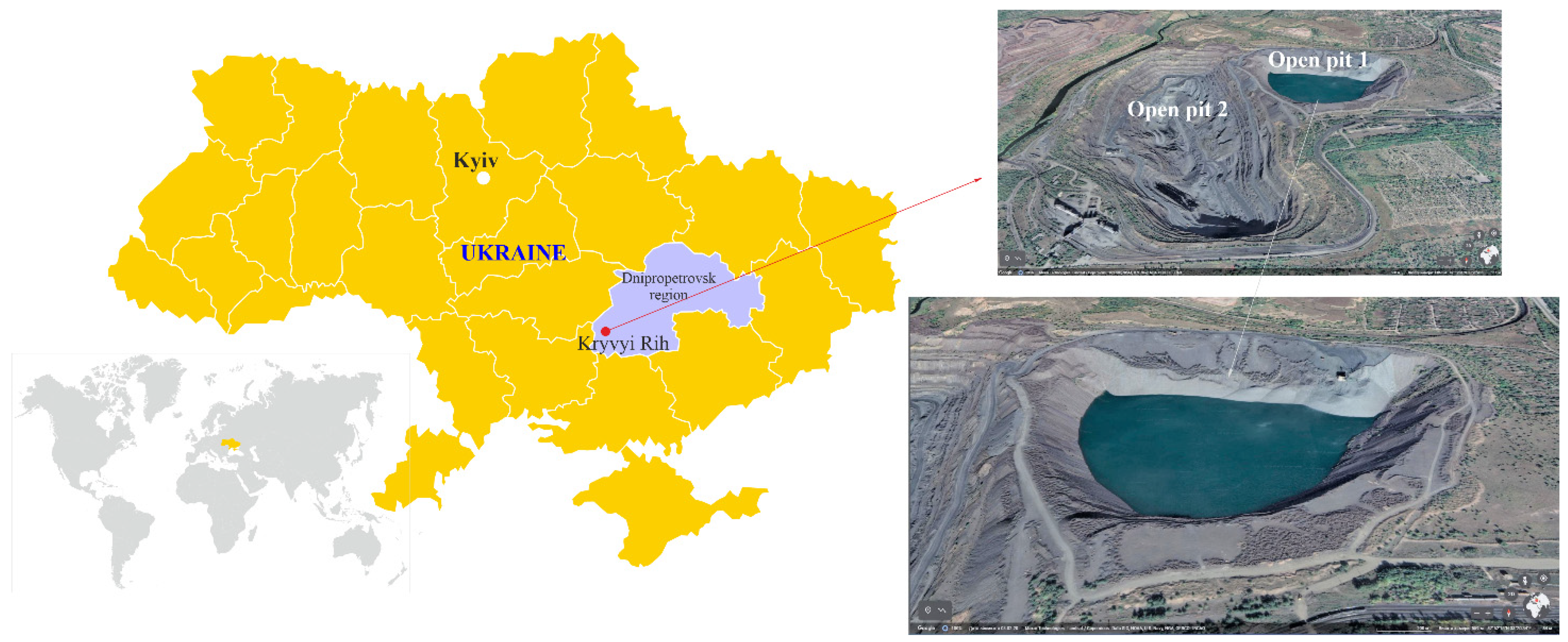
Iron-ore open pit No. 1, located in the Kryvyi Rih District of the Dnipropetrovsk Oblast, Ukraine, was chosen for this research (
Figure 1). It is a structural subdivision of the company ArcelorMittal Kryvyi Rih, PJSC. The company’s activities cover the entire production chain from iron-ore mining and coke production to the manufacture of finished metal products.
We studied the mining–geological conditions for the formation of an internal dump in the mined-out space of a depleted open iron-ore pit. Open pit No. 1, with quartz-chlorite-biotite and quartz-chlorite-amphibole-biotite quartzites, is depleted. After mining out the deposit, a technogenic remaining gap formed, which holds water inside the open pit. Open pit No. 1 was mined out in 1987. The actual open-pit parameters in the depleted state are as follows: the depth was up to 300 m (open-pit bottom level, minus 205 m); the inclination angles of the rock stratum slopes ranged from 40 to 42°, the width of the berms ranged from 5 to 50 m (in some sections, the berms were “activated”); the height of the benches ranged from 15 to 50 m. Currently, part of the open pit is filled with overburden rocks to the surface level, and the other part of the open-pit perimeter is loaded with rocks from the internal dump.
The depleted open pit No. 1 is located near open pit No. 2, and its southeastern part is filled and reclaimed for summer cottages (
Figure 1).
The surface level on its boundary ranges from +89.0 to +100.0 m. Its northern edge borders on the previously dumped and reclaimed Burshchytskyi waste dump, with a surface level of +140 m. The relief has been largely modified by mining operations (open pit and dumps). At present, the width of the mined-out open-pit space in the upper part is about 950 m, and the length is 990 m. In addition, an open pit contains a significant amount of rock mass that has been dumped over a relatively long period of time (about 40 years since the beginning of overburden rock storage). The dumping volume of the remaining gap in open pit No. 1 is about 75 million m3. Underground water is constantly coming up to the open-pit bottom. During the detailed structural mapping of open pit No. 1, a number of ruptures in the submeridional direction were revealed. The largest of them are confined to the southeastern thrust zone, which is the reason for the complex block structure of the rocks in the eastern open-pit slope. In the western open-pit slope, there is a rock-crushing zone that is 10–15 m thick, which rests on the Novokryvorizkyi Fault.
The overburden rocks from open pit No. 2 were delivered to the working site of open pit No. 1 by road transport for dumping to the recess of the ESH-11/70 walking dragline, followed by re-excavation of the rock mass under the dump slope, with the bucket unloading in the actual contour strip of the tier upper edge.
Based on the available survey materials, and taking into account the lithological type and physical-mechanical properties of soil, it was determined that the fractured rocks and rocks that allowed water to seep from open pit No. 1 to open pit No. 2 are located at +20 m level. With the current parameters of the dump slopes, landslides have occurred for the most part in sections where work is being conducted. Locally, in the dumping locations, the rock is displaced when the critical mass on the slope is reached. After a while, the rocks slide down.
There is a separate site along the south of the open-pit perimeter that is of sufficient size. The site marks are located at +100.0 to +102.0 m. Before, dumping operations were conducted at this site, which were accompanied by the formation of fractures and landslides, as a result of which the dumping was stopped. This slope is currently stable. No operations are conducted at the site. According to the mine survey data, fracturing processes have been observed to the west of this site. The eastern slope borders on the sections that have been allocated for personal agriculture. There is a residential road along the eastern slope. A residential area within 250 m is located in the northeastern section of the open pit. Therefore, operations are not conducted in this section due to the small sanitary protection zone boundary.
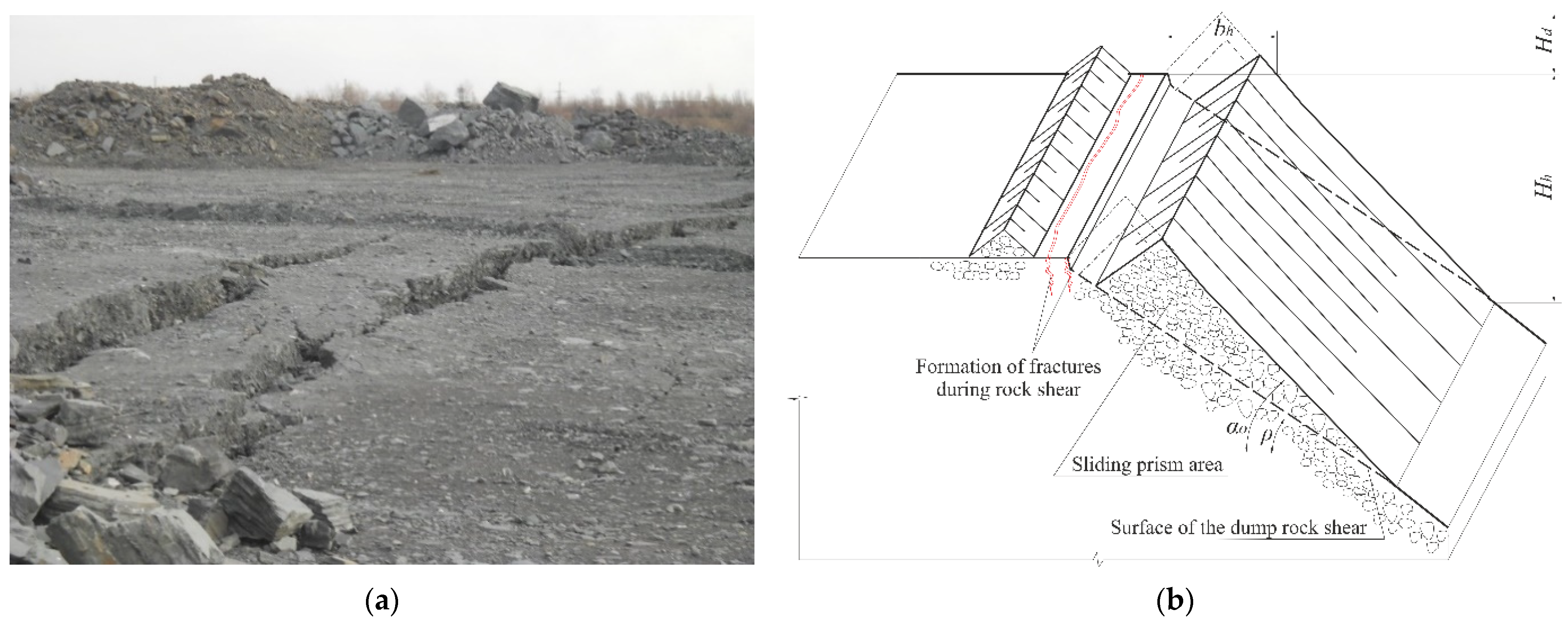
The choice of a test section for this research was conditioned by the several factors that have adversely affected the conduct of mining operations for open-pit reclamation. Firstly, in the sections where dumping was conducted (north slope), the masses adjacent to the upper edge were exposed to deformation processes. These processes manifested as the formation of a fracture along the front of the dump operations from 10 to 160 m in the north and from 7 to 96 m in the south. Secondly, the dump site slope toward the mined-out space has changed by 3–5 degrees. The most active fracturing processes were observed on the northern slope of the open-pit dump at levels from +88.0 to +90.0 m. The fractures were of a stepped shape, with variations of 50–60 cm. The fracture opening width varied from 2 to 30 cm, and the distance between them varied from 1 to 20 m (
Figure 2a). In general, the fracture formation could be represented by the basic scheme shown in
Figure 2b.
On the northern and southern slopes of the dump, there is a disturbance of their stability. The height of the dump inside the open pit in the north is 180 m, 170 m on the northwestern slope, 278 m on the southeastern slope (the dump rests against the opposite slope), 212 m on the southwestern slope, and 235 m on the northeastern slope (the dump rests against the opposite slope). In fact, with the dump slopes parameters, landslides have mainly occurred in the sections where mining has been conducted using the ESH-11/70 dragline. Locally, in the dumping locations, the rock is displaced when the critical mass on slope is reached. After a while, the rocks slide down to the open-pit bottom. The primary fracture of the rupture passes at a distance of 8–12 m from the upper edge of the dump.
All of the above has led to the loss of stability of the working site where the dragline is located. The site is fractured, with gradual subsidence from 0.4 to 2.0 m, which makes it impossible to move equipment and people for mining operations for reclamation, and the placement of the dragline is limited by its unloading radius. At the same time, the use of hydraulic excavators and mechanical shovel excavator is practically impossible because they have a small unloading radius.
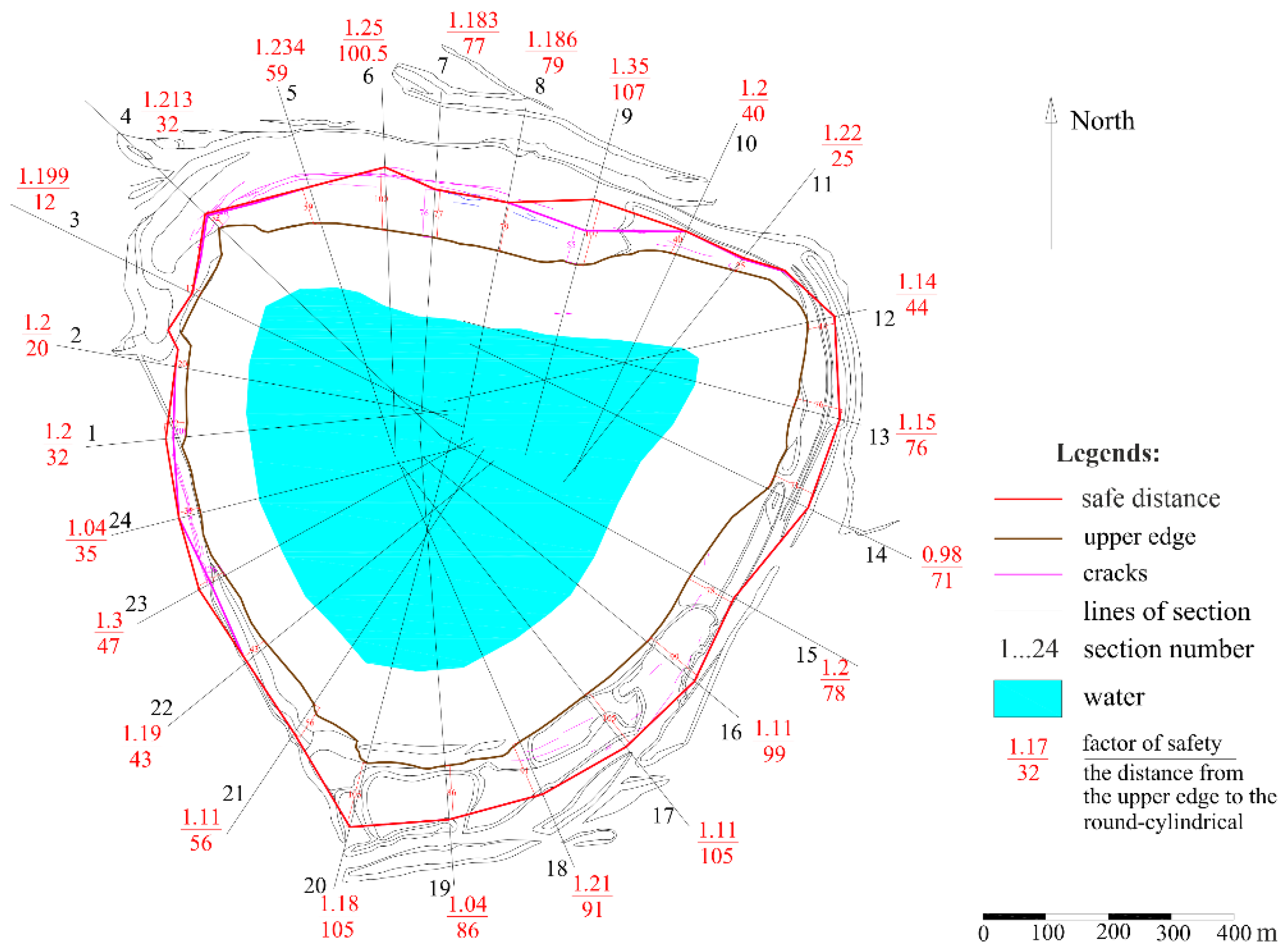
3. Materials and Methods
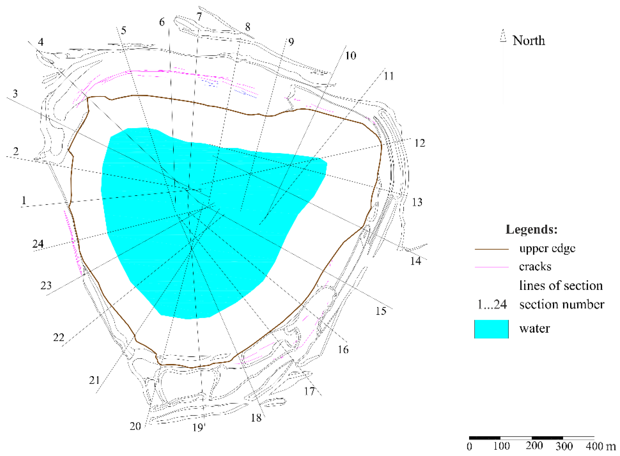
The mine surveying service the iron-ore open pit No.1 provided data on the situational plan for conducting mining operations. We identified and numbered the sections along the entire open-pit perimeter on the basis of data on the fracture formation, which we used to conduct research on the determination of the safety factor of the internal dump slopes of the open-pit mine and the safe distance for the dragline location (
Figure 3).
The internal dump is formed by rocks with different physical–mechanical properties. Only the physical–mechanical properties of bedrocks remain unchanged (γ = 25.98 kN/m3, c = 1000 kN/m2, and φ = 34°). The hard rocks, semihard rocks, gravel, and clay are placed inside the open pit space. A flooded slope has formed at the base of the internal dump, the angle of which ranges from 15 to 30 degrees. Therefore, the dump rocks were divided into dry ones in the upper area and flooded ones in the lower area. In accordance with the plans for the development of the dump, different sections were selected. The lack of areas for placing dumps means that some rocks such as clay are placed in the internal dump, which is a very dangerous practice. The presence of clay rocks and the ingress of moisture into such rocks with their subsequent additional loading with hard rocks have led to the formation of landslides in such sections. The physical–mechanical properties of clay rocks, when absorbing moisture, change, and the rock becomes plastic under the influence of water.
The physical–mechanical properties of the bedrock and rock placed in the internal dump are also different. When the destroyed hard rocks are placed in the dump, cohesion forms with their surface planes and edges, which is many times less than when these rocks are intact. Therefore, we grouped the sections with common physical–mechanical rock properties (
Table 1).
The stability of the open pit No. 1 internal dump was assessed by comparing the safety factor
Ks.f obtained as a result of the calculation with the standard safety factor
Ks.s.f. The internal dump is active, with continuous mining operations. The dragline constantly moves, with overburden rocks placed in the internal dump, so our study took into account the safety factor stated in the literature [
59]. It as stipulated that the safety factor for dump slopes with a lifetime from 3 to 10 years should be at least 1.2, and with a lifetime of up to 3 years, it should be no less than 1.15.
The safety factor of the open-pit’s internal dump slope and the safe distance of the dragline location from the slope upper edge were determined using numerical modeling. The use of this research method made it possible to reflect, with a high degree of confidence, the geomechanical situation within the open-pit field [
60,
61].
Slide 5.0 software was used to find the above-mentioned parameters (safety factor and safe distance). This software product is based on well-known classical engineering calculation methods, such as Bishop simplified, Corps of Engineers #1, Corps of Engineers #2, GLE/Morgenstern-Price, Janbu simplified, Janbu corrected, Lowe-Karafiath, and Ordinary/Fellenius. This made it possible to study the stability of the modeled rock mass system as an elastic–plastic body with the assignment of the appropriate boundary conditions. In these methods, the solution is based on the consideration of the limit equilibrium.
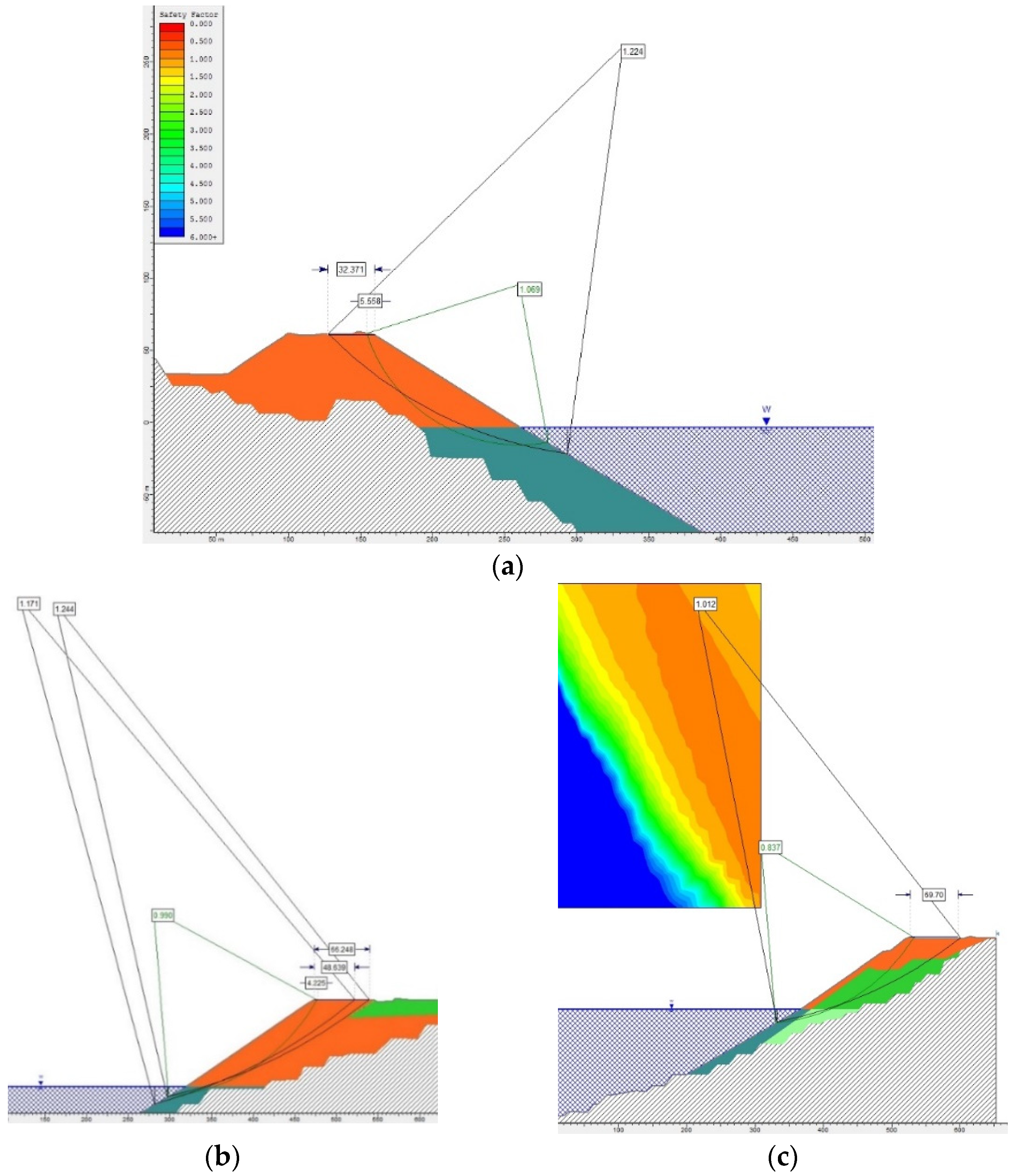
To obtain an analytical solution, the studied object (rock mass) was divided into separate fragments that slid and interacted along the boundaries. In the conducted research, the Ordinary/Fellenius method was used, namely, the method of circular cylindrical sliding surfaces. This method is appropriate to apply when the studied object is composed of homogeneous rocks and assumes that sliding occurs as a result of the rotation of the shear mass around the conventional center. It should be noted that this is a simple method, which consists of obtaining slices, and takes into account the general equation of equilibrium moments around the circular surface center. To simplify the search for a standard index of the safety factor, the “Grid Search” function was used, which allows the determination a conventional center by colors. The studied shear mass was considered as a separate block, which participated in one general movement with all its points. The constructed calculation model is shown in
Figure 4.
The model height (on the Y coordinate) corresponds to the height position of the corresponding horizons and surfaces of the open pit and dump and has levels in the different sections of the dump slopes ranging from +102.0 m to −150.0 m (open-pit bottom). The model width (on the X coordinate) corresponds to the distances between the points of the slopes and sites on the corresponding horizons and ranged from 20 to 140 m. The initial data on the dump slope angle above the water, the average height of the above-water dump part, and the average length of the dump slope projection to the water according to the studied sections are detailed in
Table 1. A load of 100 kN/m was applied to the model surface, namely, to the working site, which corresponded to the ESH-10/70 dragline weight. The mining dragline weight is an integral part of the safety factor calculation, which we used to determine the safe distance of the dragline. Additionally, during the research, the surface water level in the open pit, as well as the possibility of a seismic impact rated 4 and 7 on the Richter scale, were specified.
As noted earlier, after the mining out of open pit No. 1, a remaining technogenic gap has formed, which holds water inside the open pit. Therefore, in numerous calculations, the surface water level in the open pit at the horizon of −3.5 m was taken for the model parameters. On the one hand, water leads to a change in the physical−mechanical properties of rocks (cohesion and the internal friction angle become smaller); on the other hand, water additionally creates forces that increase the slope stability.
It should be noted that the water level rises every year. Calculations were made as of January 2023. An active open pit is located next to the internal dump, where hard rock is constantly being blasted. This has led to the occurrence of seismic vibrations in the bedrock and rock that are placed in the internal dump. In order to assess the impact of these vibrations, the registered indicators of the minimum and maximum seismic impacts were introduced into the calculations. Seismicity at a distance of 800–1000 m from the detonation site was as high as 4 on the Richter scale. At the same time, in accordance with the construction standards for the Kryvyi Rih District, the seismicity for buildings and structures was determined at the level of 6–7 points.
4. Results and Discussion
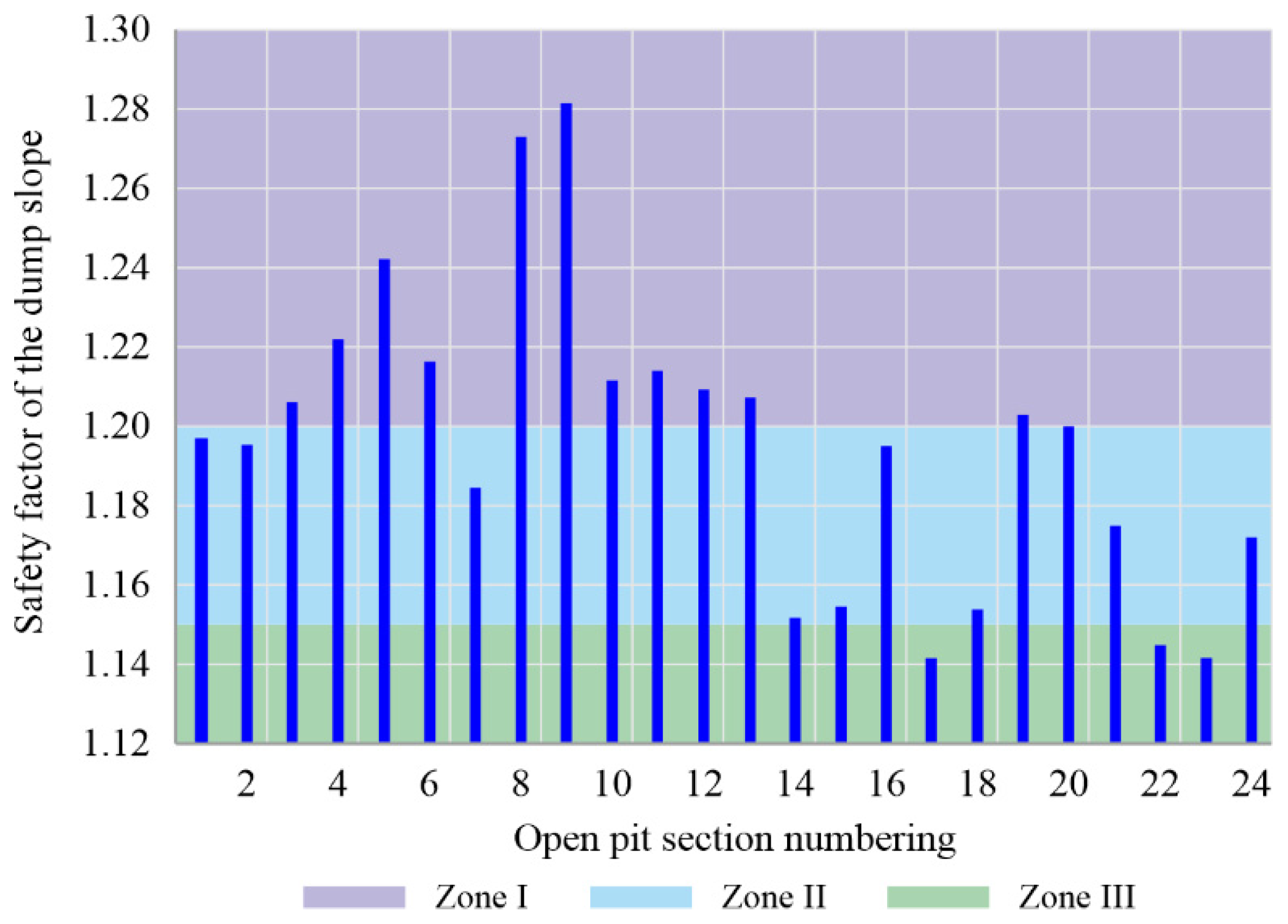
From the analysis of our research results on the bulk internal dump stability, we identified the sections most prone to deformation processes, taking into account the physical–mechanical peculiarities and hydrogeomechanical processes. For each studied section (1–24) and according to the calculation scheme (
Figure 4), the curves of the changes in the safety factor of the studied area were obtained (
Figure 5).
The general pattern of the change in the safety factor of the internal dump slopes according to the grouped sections could be represented by the dependence shown in
Figure 6.
The calculation results of the internal dump slope stability were the safety factor value and the zone of the maximum shear stress location, indicating the position of the expected sliding curve. The highest safety factor values were observed in sections 1–12, related to the western open-pit slope. This situation is conditioned by the fact that the dump slope borders on hard bedrock that has greater stability. A similar pattern was observed within the boundaries of sections 19–20. Additionally, the analysis of the data given in
Figure 6 indicated the possibility of occurrence of clay, loam, and sand inclusions in section 7, because the internal dump of open pit No. 1 has been formed from the overburden rocks of open pit No. 2. All the overburden rock volumes as well as the sites of their mining were identified at the stage of open-pit planning and were adjusted according to the production needs in terms of the mining development plan for a particular year. Therefore, overburden rocks may have different compositions, physical properties, and sizes of individual elements/pieces. Overburden rocks, in our conditions, were stockpiled into the dump in a bulk way, and the parameters of the dump slope safety factor ≤ 1.15 just confirmed the presence of clay, loam, and sand inclusions, which, in terms of strength degree, are considered soft and loose rocks. In the southern (sections 18–22), eastern (sections 14–15), and southeastern (sections 17–18) areas, the dump slopes border on sediments represented by clays, loams, and sands with a strength of 2–3 on the Mohs scale, respectively. This caused a decrease in the safety factor by 22%. At the same time, it is prohibited to conduct mining operations within the boundaries of sections 17, 22, and 23, regardless of the dump slope lifetime, because
Ks.s.f ≤ 1.15.
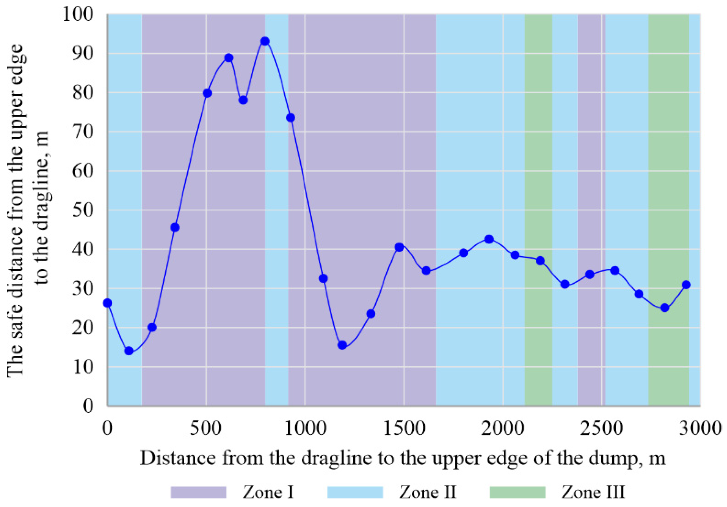
The applied approach to determining the safety factor of the working dump slopes, taking into account the distances between the studied sections ranging from 74.2 to 190.2 m, made it possible to find the safe distance for placing the dragline along the entire open pit perimeter, which changes according to the dependence given in
Figure 7.
Based on the research results, a significant difference was noted in the safe distance for placing a dragline within the standard safety factor value of the dump slopes:
- −
The minimum safe distance value according to group I is 14 m in section 2 (1.19); 31 m according to group II group in section 19 (1.2), and 25 m in according to group III group in section 23 (1.15);
- −
The maximum safe distance value according to group I group is 93 m in section 8 (1.27), 40.5 m according to group II in section 13 (1.2), and 42.5 according to group III group in section 16 (1.19).
It follows from the above that an increase in the safe distance is conditioned by the presence of a sufficiently stable open-pit slope section, which provides additional holding forces to the dump slopes. Beyond the determined safe distance boundary, the round-cylindrical sliding surface actually begins to cross the open-pit slope bedrock, which leads to an increase in the dump slope safety factor, because bedrock have higher cohesion, internal friction angle, and specific weight. These rocks are hard, strong, and in a natural state, which increases the stability of the whole mass together with the dump. In the water-flooded area of the dump slope rocks, the resistance to shear from the active pressure prism is significantly lower compared with that of the “dry” dump slope area. In addition, the disturbance of the working site stability in the possible sliding prism strip occurs under the action of static (weight of dump-forming machinery and dragline) and dynamic (vibration of the operating dragline and rock blasting) forces when the front of the dump formation advances.
By determining safe boundaries, it was possible to assess the remaining sites where the equipment can be placed and the impact of sites where fractures and the boundaries of possible landslides can be formed. It should be noted that the fractures have formed in the sections where the front of the dump formation operations has moved away from the bedrocks to a significant distance. Based on the surveying service data, the fracture formation has been preceded by sound manifestations. The fractures have gradually propagated and have taken the form of steps. The formation of fractures is monitored by a special surveying department of the enterprise. All manifestations are fixed and monitored for a considerable period of time. In the case of a detection of a formed or developing fracture, the service warns dragline drivers and dump truck drivers and also puts up signs prohibiting operations in the section. After stopping the formation and propagation of fractures, they are monitored for some time; then, it is determined whether it is possible to continue operation on the internal dump formation in this section.
The interpolation of the obtained data on the change in the safe distance for placing the dragline according to the studied sectional groups made it possible to determine the boundaries of the possible rock shear with distances from the upper edge and the safety factors along the open-pit perimeter (
Figure 8).
The possible rock shear boundaries that we determined made it possible to propose a sequence of mining operations for internal dump formation in three stages, in which the width of a possible sliding prisms of a part of the transfer sites changes:
- −
Within the influence of the open-pit slope contours at a distance from 5 to 15 m;
- −
Beyond the open-pit slope contours at a distance of more than 50 m;
- −
The transitional period between stages at a distance within 15–50 m.
The above-mentioned mining–geological and geodynamic conditions for the internal dump formation influence the geomechanical calculations of their stability along the slopes of the open-pit perimeter. The slope angles of the dump pocket in the upper area at 1/3 of the height have a value of 42°; in the middle and lower area, this value is 36°.
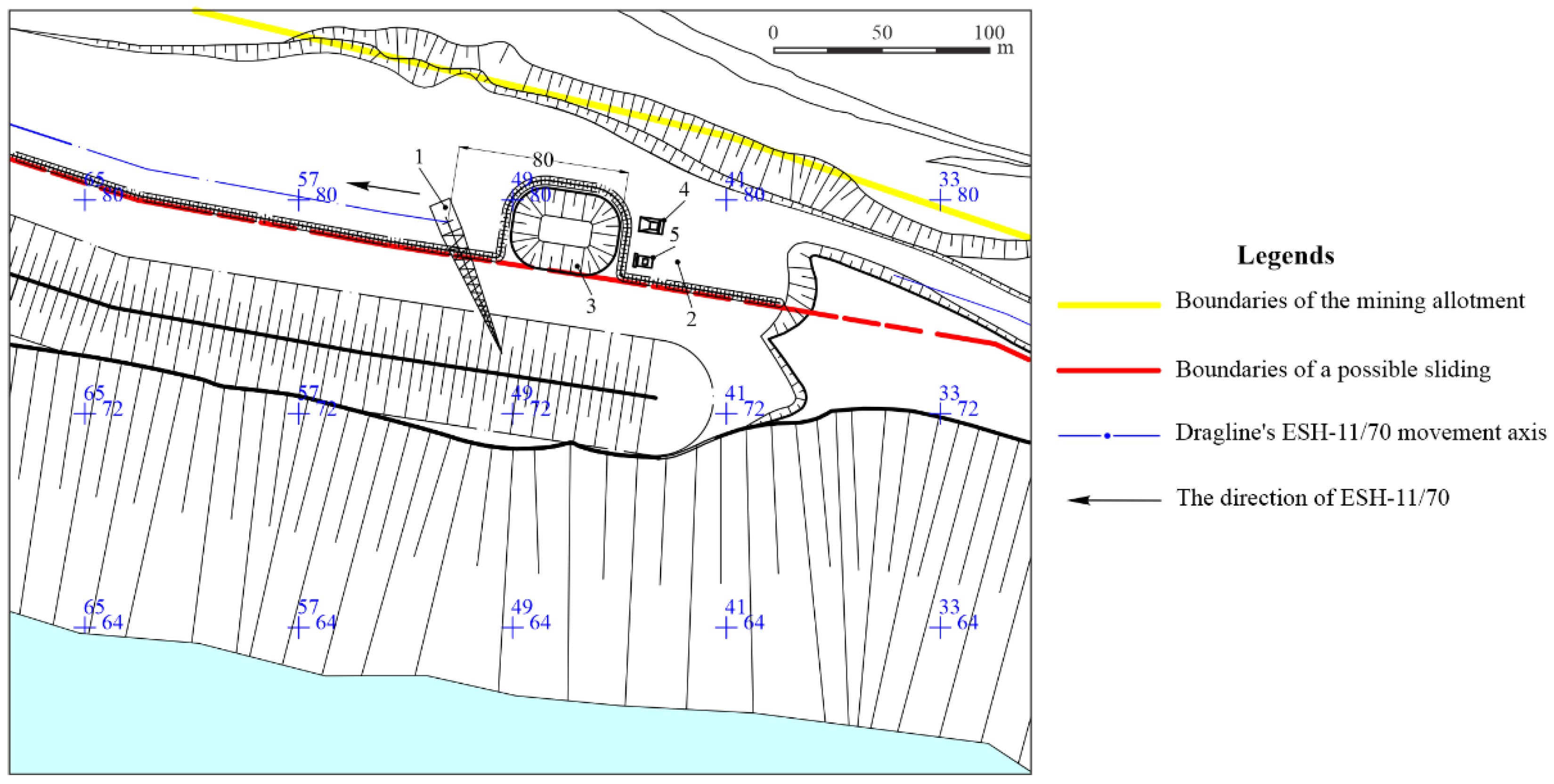
Based on the determined safe distance for the mining equipment placement when using existing equipment in iron-ore open pit No. 1, we propose the following internal dump construction solutions:
Along the perimeter of the formed section, outside the possible sliding prism (determined by the mine surveying service) and at a distance of at least 1.5 m from the upper edge of the bench, a bulldozer should form a protective embankment 3–4 m wide. A 15 m deep recess for unloading hard overburden rocks should be formed by the ESH-11/70 dragline with rock unloading into the internal open-pit space. The volume of the works for the construction of a recess should be about 151,400 m
3 (
Figure 9).
The overburden rocks from the recess are unloaded into the formed space of open pit No. 1 by the ESH-11/70 dragline. During ESH-11/70 dragline operation, it is prohibited for other equipment or workers to be in the bucket action area. Before the start of the dragline operation, its crew put up a warning sign stating “no entry for dump trucks”.
In the event that fractures begin to form outside the zone of possible shearing or there is another threat of slope sliding, it is necessary to immediately stop the work and move the ESH-11/70 dragline away to a safe distance until the rock mass stabilizes.
After the recess is formed, the ESH-11/70 dragline moves to another section for work, or the boom is turned in the direction opposite to the mined-out space, lowering the bucket onto the site. The boom should not be above the running surface or sites where dump trucks are maneuvering. After the dump trucks fill the recess, the dragline returns to its original position. The ESH-11/70 dragline moves with the boom set in the direction opposite to its movement and with an empty bucket. While the dragline is moving, entry to the unloading site on the horizon is prohibited and is limited by a corresponding sign. Unloading dump trucks in the recess is permitted only when the dump trucks are outside the reach of the dragline’s boom or counterweight dimensions.
At the beginning of loading the recess, the sign “no entry for dump trucks” is removed. The ESH-11/70 dragline stops operation during the movement, maneuvering, and unloading of dump trucks. The transportation of overburden rocks from open pit No. 2 to the unloading site is performed by road.
Upon reaching the unloading site, the dump truck loaded with rock reduces speed and, if there is a free place for unloading, begins maneuvering operations so that it reverses to unload outside the possible sliding prism perpendicular to the upper recess edge at a distance of at least 5 m from of the rear wheel of the dump truck.
The distance between dump trucks placed for unloading and dump trucks waiting for unloading is selected based on the minimum required distance.
Hard overburden rocks dumped into cones by dump trucks are moved by a bulldozer to a recess formed by the ESH-11/70 dragline. The bulldozer moves perpendicular to the upper edge with a share in the direction of the recess. When planning a site for unloading rocks, the permissible distance from the upper edge of the recess to the edge of the crawlers should be at least 2 m.
When using the ESH-6.5/45 dragline-excavator, the safe distance for the point of its placement relative to the upper edge of the single-tier dump in the mining–technical conditions of the north-astern slope of open pit No. 1 includes the actual sliding prism width within 16–20 m. The safe distance from the ESH-10/70 dragline’s outer contour of its base to the single-tier dump upper edge is 25 m and includes the actual sliding prism width of 14 m and the attenuation zone of subsidence deformations up to 11 m wide.
The guidelines for the territory of Ukraine specify the service life and safety factors for mine workings (benches, open-pit slopes, and dumps, including working and nonworking ones). In accordance with current guidelines, a minimum safe service life for a working dump slope is 3 years (the slopes constantly change their status from working to temporarily nonworking).
The obtained research results made it possible to determine the boundaries that the dragline should not cross in order to avoid an emergency situation. When constructing an internal dump, mining equipment is placed outside of certain lines, which allows safe operations, restricts movement in the immediate vicinity, and allows warnings to be provided to workers. For the mine surveying service, these scientific studies are the basis for monitoring the formation of fracturing and zones of possible dump shear.
Our analysis of the current state of the dump formation processes into the open-pit mined-out space suggests that the main reasons for the development of landslides on the internal dump slopes are as follows:
- −
Exceeding the slope height during internal dumping to the full height of the open-pit slope;
- −
Increasing the water level in the mined-out space at the base of the dump slopes, resulting in a change in the physical–mechanical properties of rocks entering the water;
- −
Dumping onto a high internal dump of soft rocks containing clay, which, during rain, even in the “dry” dump slope area, are saturated with water and turn into a sliding base;
- −
The action of the mining equipment weight and the dynamic forces arising during the operation of the equipment;
- −
Seismic actions that occur during large-scale blasting operations in an adjacent open pit.
The working site width on benches and in the dump should ensure the placement of mining and transport equipment outside the rock sliding prism. If there are signs of sliding in the open pit or of the dump slopes, work is stopped, and the equipment and people are taken to a safe place, which is reported to the site management. The dump pockets are formed in sections that are 200–300 m long. In the event of the formation of dangerous shear processes in freshly dumped rock, dumping operations in this section are suspended and transferred to the adjacent one.
The sequence of dump formation using dragline and bulldozer equipment, taking into account the developed recommendations and safety measures, gives the opportunity to fill the mined-out space of the water-flooded open pit No. 1 until 2042. This sequence is as follows:
- −
Dump formation on the site within sections 1–5 in the northwestern area of open pit No. 1 at a +60 m horizon with a recess formation;
- −
The formation of dumping cones on the northern slope site within sections 5–9 of open pit No. 1 by additional loading a fractured mass of the sliding prism;
- −
Dump formation on the site within sections 10–12 of the northeastern area of open pit No. 1 with a recess formation;
- −
Dump formation on the site within sections 13–16 of the eastern area of open pit No. 1 with a recess formation;
- −
Dump formation on the site within sections 18–20 of the southern area of open pit No. 1 with a recess formation.
During the increased danger of using the ESH-11/70 dragline to form an internal dump for hard overburden rocks from open pit No. 2 to open pit No. 1 during forced operation within the boundaries of a possible sliding prism, provided that the shear processes are stabilized and the formation of fractures is stopped, we propose reducing the dump pocket width up to 10–15 m with the placement of a recess for unloading dump trucks outside a possible sliding prism but within the ESH-11/70 dragline digging radius. If fractures begin to form outside the zone between the upper dump edge and the dragline’s movement axis or close to it, immediately stop the work until the rock mass stabilizes.
Further research is proposed to consider the possibility of building a cableway with the ability to unload rocks close to the water and generate less dust to enable the use of the mined-out space of open pit No. 1 in the adjacent village sanitary zone for dumping hard overburden rocks from open pit No. 2.
5. Conclusions
As a result of the conducted research, a geomechanical model was constructed, characterizing the stages of an internal dump formation in the mined-out space of an iron-ore open pit and adequately reflecting the deformation processes that occur in dumped rocks, taking into account their physical–mechanical properties and hydromechanical processes.
The determined safety factors of the slopes of the internal dumps formed in the mined-out space of the open iron-ore pits and the determined safe distances from the outer contour of the mining equipment base to the single-tier dump upper edge allowed us to assess the effectiveness of using the existing mining equipment. It was determined that with the existing equipment (ESH-11/70), it is possible to perform works only within the boundaries of sections 1–5, 6–9, and 18–20. In the southwestern area, the difficulty arises owing to the size of the working sites. Within sections 1 and 21–24, there are restrictions related to the width of the site and the minimum safe distance from the upper edge.
The height of the above-water dump area will decrease over the years if the dump has constant levels at the upper sites. The underwater area creates additional holding forces due to water and gravity. With a standard safety factor value of the dump working slopes with a lifetime of 3 to 10 years, the safe distances from the upper edge will range from 14 m to 23 m.
The performed calculations for the stability and predictive water level indicators confirm that the identified sections on the northwestern dump slope are sufficiently stable with a standard safety factor of 1.2. The calculations for other sections indicate that, using the existing equipment, it is possible to perform works with the lifetime of dump for up to 3 years. In the location of sections 17, 22, 23, dump formation is prohibited (the safety factor is less than 1.15). Under such conditions, the ESH-11/70 operating parameters do not correspond to the conditions for its safe placement.
Slope stability can be affected by a range of external factors, such as weather conditions, seismic activity, and human activities. These factors were not fully accounted for in this study, which may limit the applicability of the results. Our study covered only a short period of time and may not reflect these changes, limiting the understanding of the long-term slope behavior.


 ,
, 


