Article

Battery Thermal Management: An Application to Petrol Hybrid Electric Vehicles

by
Raja Mazuir Raja Ahsan Shah
1,*,
Mansour Al Qubeissi
2,
Hazem Youssef
2 and
Hakan Serhad Soyhan
3,4
1
College of Engineering Technology, University of Doha for Science and Technology, Doha 24449, Qatar
2
School of Mechanical Engineering, Coventry University, Coventry CV1 2JH, UK
3
Department of Mechanical Engineering, Esentepe Campus, Sakarya University, Sakarya 54050, Turkey
4
Team-SAN Ltd. Sti., Teknokent, Serdivan 54050, Turkey
*
Author to whom correspondence should be addressed.
Sustainability 2023, 15(7), 5868; https://doi.org/10.3390/su15075868
Submission received: 22 January 2023 / Revised: 27 February 2023 / Accepted: 8 March 2023 / Published: 28 March 2023

Abstract

:
Battery thermal management systems (BTMS) in hybrid electric vehicles can be complex and heavy. They tend to increase energy consumption, leading to higher carbon dioxide emissions. In this study, a new approach was investigated for the potential use of four fuel components as coolants for direct liquid-cooled (LC)-BTMS, N-Pentane, N-Hexane, N-Butane, and Cyclo-Pentane. The performance of the fuel components was numerically analysed and CFD modelled using ANSYS Fluent software. Several meshing iterations of the lithium-ion battery (LIB) module were performed to conduct mesh independence check for higher accuracy and less computational time. The LIB module was simulated, in comparison to a free air convection (FAC)-BTMS as a benchmark, at three discharge rates (1C, 1.5C, 2C) for each of the inlet velocity values (0.1, 0.5, 1 m/s). Results show that FAC-BTMS exceeded the LIB module optimal operating temperature range (293–313 K) at 2C. On average, at the worst condition (lowest inlet velocity and highest discharge rate), all fuel components of the LC-BTMS were able to maintain the LIB module temperature below 288 K. That is at least 4.7% cooler compared to FAC-BTMS, which renders the new approach viable alternative to the conventional BTMS.

1. Introduction

Over the past few centuries, the world has relied on fossil fuels as the main energy source to power vehicles with internal combustion (IC) engines. This has come at a great cost to the environment and human health, as 20% of all carbon dioxide (CO2) emissions originate from road traffic [1]. As a result, electric vehicles (EVs) have begun to dominate the automotive industry to reduce CO2 gas emissions. In 2015, 550,000 units of EVs were sold, and this subsequently increased to 774,000 units in 2016 [2]. However, EVs have several inherited issues, such as range anxiety [3], long charging time [4], and the availability of charging infrastructures [5]. One of the solutions for these issues is to have different powertrain topologies, such as hybrid electric vehicles (HEVs) [6].
Rechargeable lithium-ion batteries (LIBs) are the most common type of energy storage for HEVs. However, LIBs generate heat while charging or discharging, and if this heat is not dissipated, it affects the battery’s performance and causes it to have a reduced lifespan, leading to thermal runaway [7]; thus, the heat generated by LIBs must be adequately thermally managed. For instance, Sato [8] investigated the effect of LIBs operating above 323 K, which showed a decrease in charging efficiency and LIB longevity.
To mitigate these concerns, a battery thermal management system (BTMS) is introduced to cool LIBs at an optimal operating temperature range of 293–313 K [9]. The temperature difference within LIBs could also influence their longevity and be kept below 5 K [10]. Several cooling techniques could be implemented, such as direct and indirect cooling, and with several cooling media, such as air, liquid, phase-change material (PCM), and heat pipes (HPs) [11].
The heat generation inside LIBs is a complex process that requires knowledge of how the electrochemical reaction rate varies with time, temperature, and current flows. Kim et al. [12] presented the heat generation of LIBs as Q ˙ = I (U − V) − I (T d U d T ), where Q ˙ , I, U, and V are the rate of heat generation, the electric current passing the cell, open circuit voltage, and the cell voltage of the LIB, respectively. The resistance loss and reversible entropic heat in the electrochemical reaction are denoted by I (U − V) and (T d U d T ), respectively. During charging and discharging processes, LIBs generate three types of heat: (1) the activation of irreversible heat due to the polarisation of the electrochemical reaction, [13] (2) joule heating due to ohmic losses [14], and (3) reversible reaction due to the entropy change [15].
The LIB thermal runaway is a common issue when it reaches the maximal threshold temperature. The thermal runaway is caused by the exothermic reactions among the anode, cathode, and electrolyte [16]. These exothermic reactions are caused by short circuits, high-speed charging/discharging, and overcharging LIBs [17]. The thermal runaway of a single LIB may lead to the thermal runaway of the entire LIB pack, which causes severe damage [18].
BTMSs can be categorised into three strategies: (1) active, (2) passive, and (3) hybrid [19,20]. Active BTMSs often use air or a liquid cooling medium where the cooling medium can be in either direct or indirect contact with LIBs. Pumps and fans are used to circulate the cooling medium and transfer the heat to the ambient condition. Passive BTMSs implement PCM and HP on the surface of LIBs to improve the heat transfer with the boundaries [11]. Lastly, hybrid BTMSs adapt PCM + air, PCM + liquid, or PCM + HP.
Air-cooled is a preferable BTMS solution due to less weight and system complexity compared to those of liquid-cooled solutions. An efficient air-cooled (AC)-BTMS can remove excess heat generated from LIBs during charging/discharging and maintain the optimal operating temperature. However, in forced AC-BTMSs, air cooling capacity is limited due to poor thermal conductivity, which increases the working temperature and causes thermal imbalances within LIBs under harsh operating conditions, in addition to having difficulty in achieving uniform air distribution [21]. Moreover, forced AC-BTMSs require higher volumetric flow to achieve similar cooling performance to that of other types of BTMS; thus, AC-BTMSs are not efficient in controlling the temperature in LIBs that have fast charging/discharging rates.
For fast charging/discharging applications, direct liquid-cooled (LC)-BTMSs are preferred since they have a higher heat coefficient than AC-BTMSs [22]. A dielectric cooling medium is used in direct LC-BTMSs due to its electrically nonconductive properties and high thermal stability. Direct LC-BTMSs require two to three times less energy compared to AC-BTMSs to maintain the same average temperature of LIBs [23]. One of the dielectric cooling media is oil. The rate of the heat transfer of oil was significantly higher than that of air at the same mass flow rate [24]. However, a newer experiment found that using mineral oil as a dielectric coolant introduced weight to a vehicle, which worsened its performance and increased its energy consumption [25]. The 3M Novec-7000 is another type of dielectric coolant, and it is commonly used in direct LC-BTMSs. For instance, Thakur et al. [22] developed the boiling LIB cooling method using 3M Novec-7000. At a discharge/charge rate (C) of 10C, the performance of direct LC-BTMSs was examined by comparing an AC-BTMS and a boiling LC-BTMS. Using the air-cooled system, the LIB temperature increased to 353–363 K, whereas with total immersion in the 3M Novec-7000, the LIB temperature remained at 308 K.
Implementing indirect LC-BTMSs can be considerably more complicated and expensive than direct LC-BTMSs. Indirect LC-BTMSs are where the cooling media do not get in direct contact with LIBs, and are mainly used to prevent electrical conduction with LIBs whilst dissipating heat. However, there are two issues with indirect LC-BTMSs: (1) leakage at cooling connections that cause LIBs to short circuit, and (2) high thermal resistance due to the electrically insulating coating that reduces the heat transfer performance [26].
For passive PCM-BTMSs, PCM is designed to surround LIBs. When LIBs heat up, the PCM softens and absorbs the heat. When LIBs cool off, PCM hardens and releases all the heat into the atmosphere. PCM stores thermal energy via the latent heat phase of transitions [27]. Moreover, it has a large amount of latent heat; and during LIBs discharge, it acts as a heat sink. PCM can effectively lower LIBs’ maximum temperature and reduce the temperature differences at the end of the discharge cycle [28]. However, there are three disadvantages of PCM-BTMSs, namely (1) low thermal conductivity, (2) leakage problems, and (3) limited capacity of heat absorption after melting [29].
On the other hand, passive HP-BTMSs have high thermal conductivity and are used to maintain the temperature of LIBs within the optimal working temperature range [30]. For example, Nasir et al. [31] implemented HP-BTMS to cool HEVs LIBs, and it was found that the system was able to reduce the maximum LIB temperature by 287.7 K and maintain an average temperature below 323 K [31]. The advantage of using HP-BTMSs is providing a lightweight system with an extended lifecycle. However, the main concern with HP-BTMSs is the relatively high cost compared to other cooling techniques [29].
To reduce the overall weight of HEVs and, subsequently, the vehicle energy consumption, the ideal volume and weight of BTMSs should be less than 40% of the LIB module [32]. These requirements motivate the need to find alternative solutions where fuel (already stored in the tank) has the potential to maintain the LIB’s temperature. The concept of using fuel as the cooling medium for BTMSs, introduced in [33], can reduce the weight of EVs and improve vehicle performance and energy consumption.
Many hydrocarbon molecules in petroleum are found as good dielectrics. However, dielectric permittivity can be altered by the number of carbon atoms in the fuel composition. For instance, using N-Heptane as a coolant for BTMSs managed to control the LIB’s maximum temperature at discharge rates 1C and 2C by not more than 280.9 K and 290.9 K, respectively, compared to a LIB without BTMS [33]. Fuel must have good material compatibility with LIBs to protect the elastomer seals, copper, and insulation materials from any harm. High flash point reduces the fire risk in high temperatures and improves safety. Fuel components that have dielectric constants ( κ ) lower than 2 are suitable for direct LC-BTMSs [34].
From the above literature, the challenges are to identify a suitable cooling medium for LIBs that can maintain the optimal operating temperature range and the low-temperature differences between LIBs. Additionally, this approach can reduce the overall weight of HEVs and minimise system complexity. In this paper, we investigated the cooling strategy of petrol components for direct LC-BTMSs using computational fluid dynamics (CFD) for HEVs application. The approach is the first of its kind and has not been revealed elsewhere before, to the best of our knowledge. A commercial software, ANSYS-Fluent, is used to simulate LIB thermal behaviour at different discharge rates. Dielectric components of petrol molecules are investigated for their suitability in BTMSs.

2. Modelling and Parameterisation Study

A transient 3D modelling of LIBs and their enclosure is conducted using the commercial CFD software ANSYS-Fluent. The system design is produced using CATIA V5. Both thermal and electrochemical interactions are accounted for and coupled in the simulation. The main result indicators are the individual LIB maximum temperature, and the temperature differences across the domain and between LIBs. Five cooling media are considered in this study: air, N-Pentane, N-Hexane, N-Butane, and Cyclo-Pentane, based on a direct LC-BTMS strategy. The dimensions and materials used in LIB sub-components are provided in the following sections. In addition, the governing equations used in the numerical simulations are highlighted, along with the coolant properties.
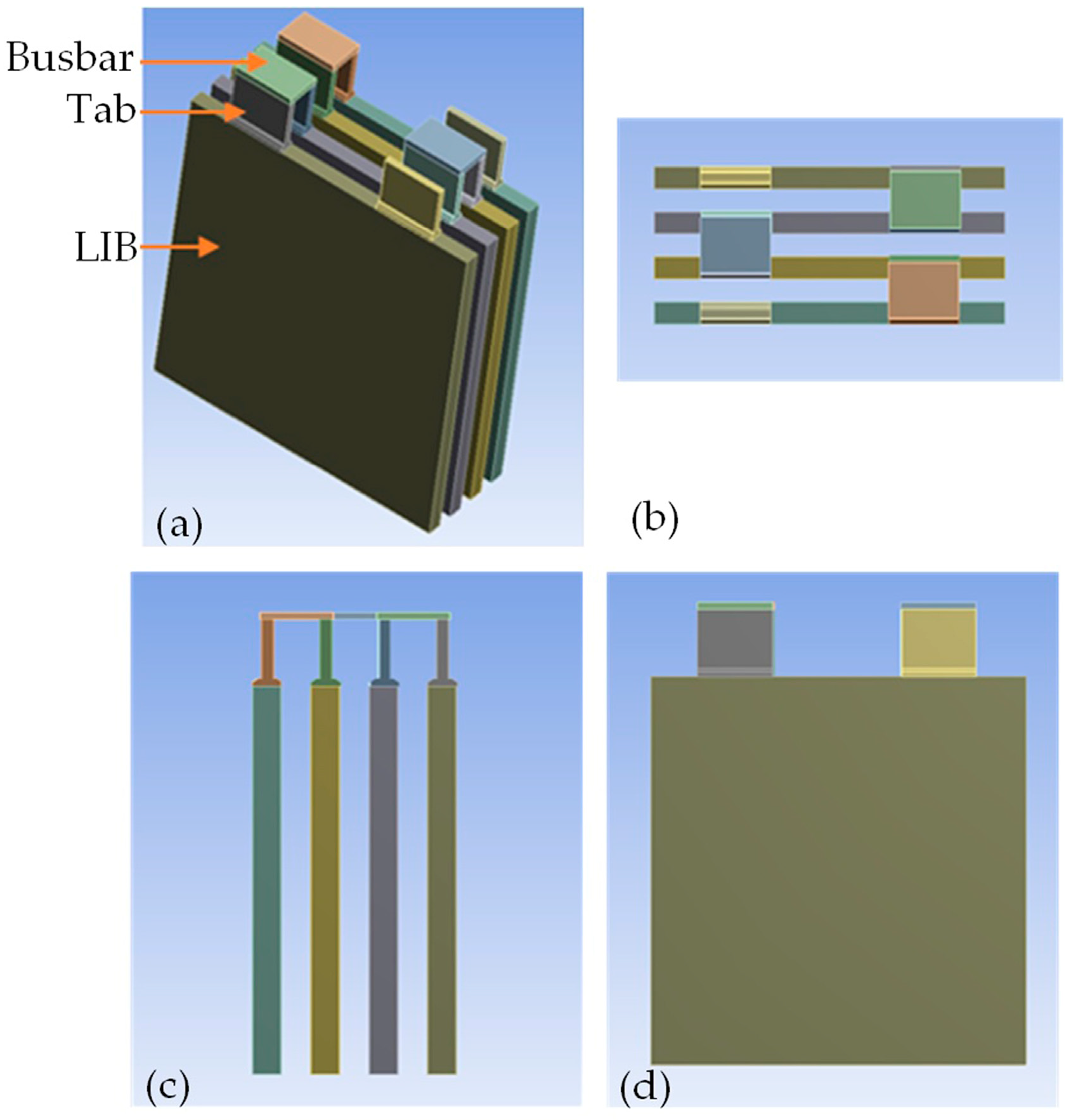
2.1. LIB Module

The LIB module used in this study consists of four LIBs, as shown in Figure 1. The configuration of the LIB module is based on 4S1P (four LIBs in series and one LIB in parallel). Each of the LIBs is connected to two aluminium tabs (positive and negative connections). These tabs are connected via copper busbars to form the LIB module. In total, the sub-components of the LIB module are four LIBs, eight tabs, and three busbars. LIBs are spaced by 5 mm gaps for the cooling medium. The properties of the LIB and tab and busbar are shown in Table 1 and Table 2, respectively.
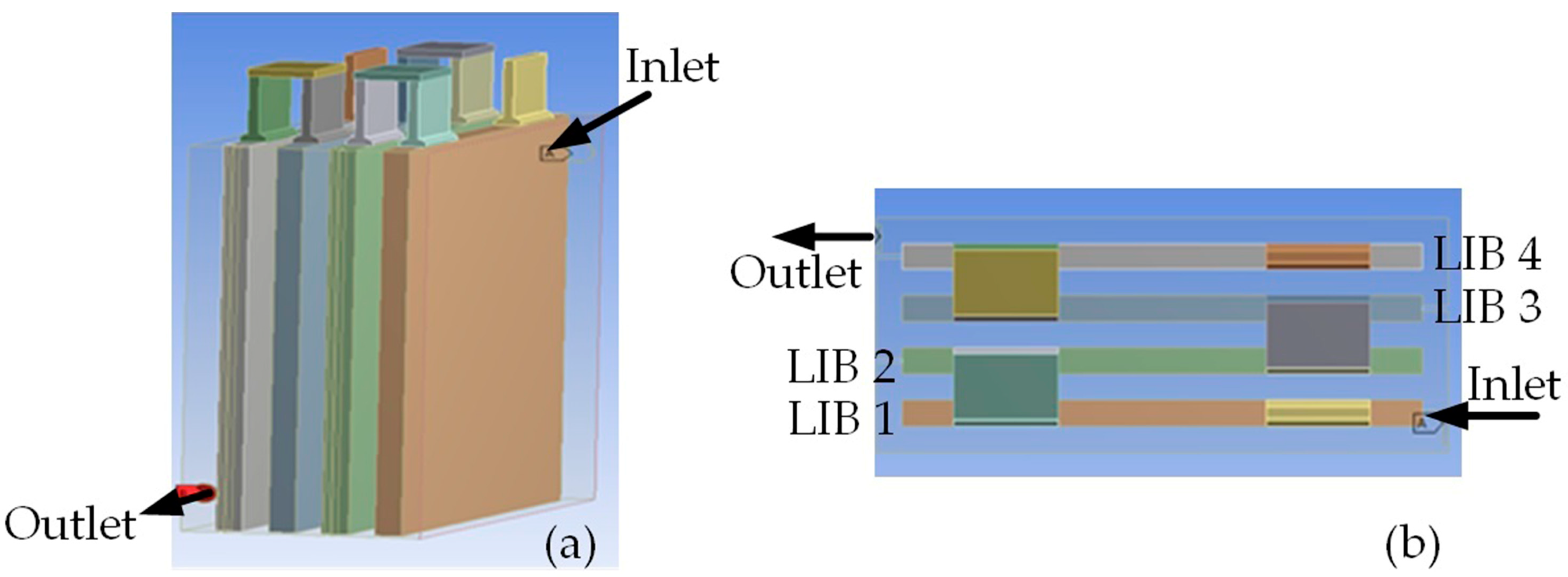
The LIB module enclosure has inlet and outlet ports for the cooling medium, as shown in Figure 2. An inlet port is on one side at the top of the wall, and the outlet port is on the diagonally opposite side, positioned at bottom of the wall. The design of the inlet and outlet ports allows for the cooling medium to flow through the LIB module and to fully immerse the LIB module surfaces. This approach can ensure uniform temperature distribution across the LIB module, which helps maintain the optimal working temperature range between 293 and 313 K.

2.2. Meshing

CFD simulation requires high-quality mesh and appropriate convergence criteria to produce accurate and reliable results without requiring high computational time and power. Hence, mesh convergence is performed to ensure the highest possible accuracy. Two different types of mesh are used for the LIB module enclosure and the LIB module, tetrahedral and structured.
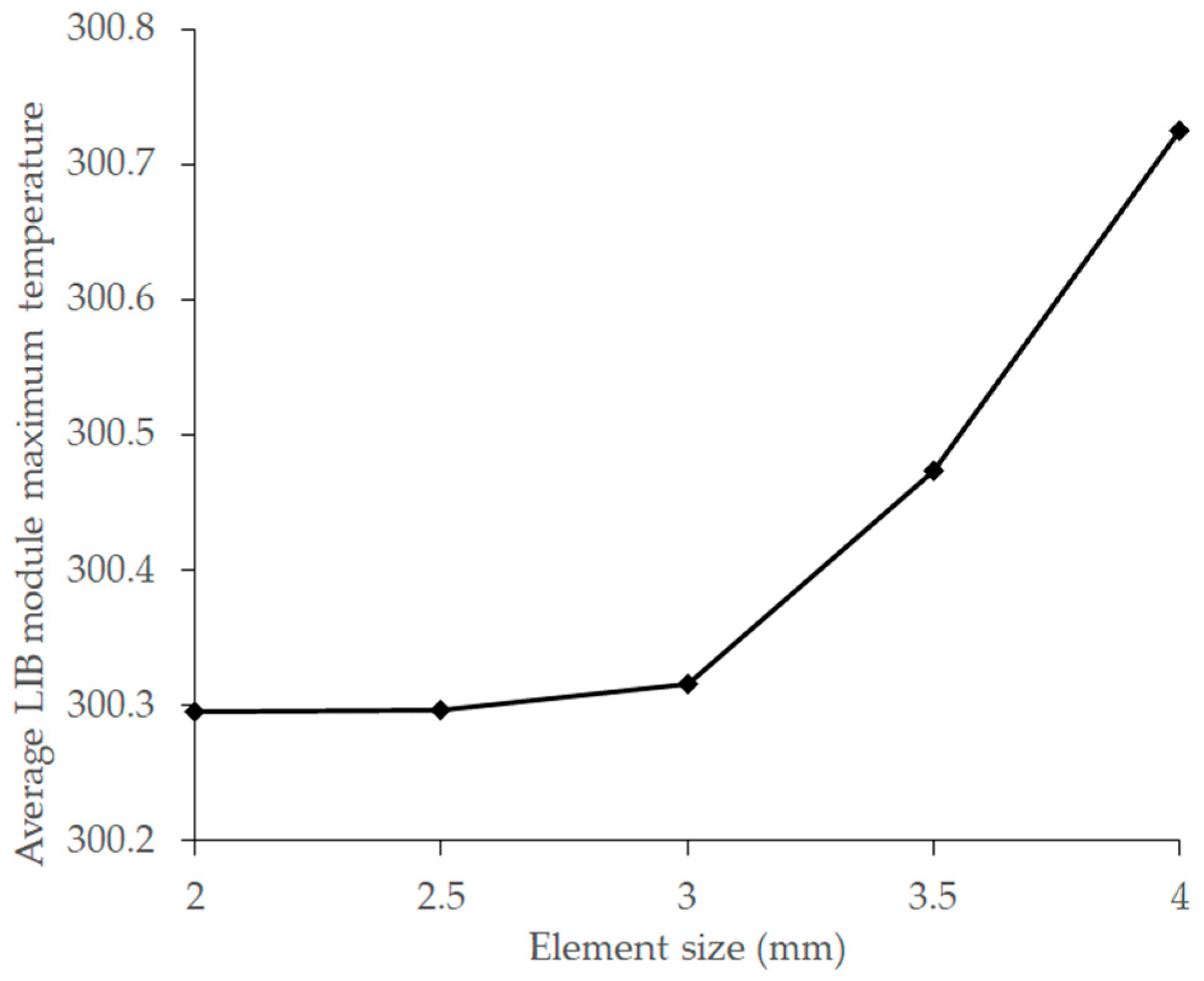
The LIB module enclosure is meshed using tetrahedral elements due to its complex geometry and to avoid any distortion. For the LIB module, hexahedral elements are used with four different element size refinements. Four simulation iterations are run based on the full depletion of the LIB module. The element sizes are set between 2 and 4 mm, with 0.5 mm intervals. The average LIB module maximum temperature is plotted against the number of elements.
As shown in Figure 3, at an element size of 3 mm, the mesh gave a converged model. The differences between the average LIB module maximum temperatures of element sizes 2 mm, 2.5 mm, and 3 mm are negligible. Element sizes of 2 mm and 2.5 mm will require high computational time, but contribute insignificantly to accuracy. Hence, it is more practical to rely on the 3 mm element size. The total number of elements used for the LIB module is 125,068. 
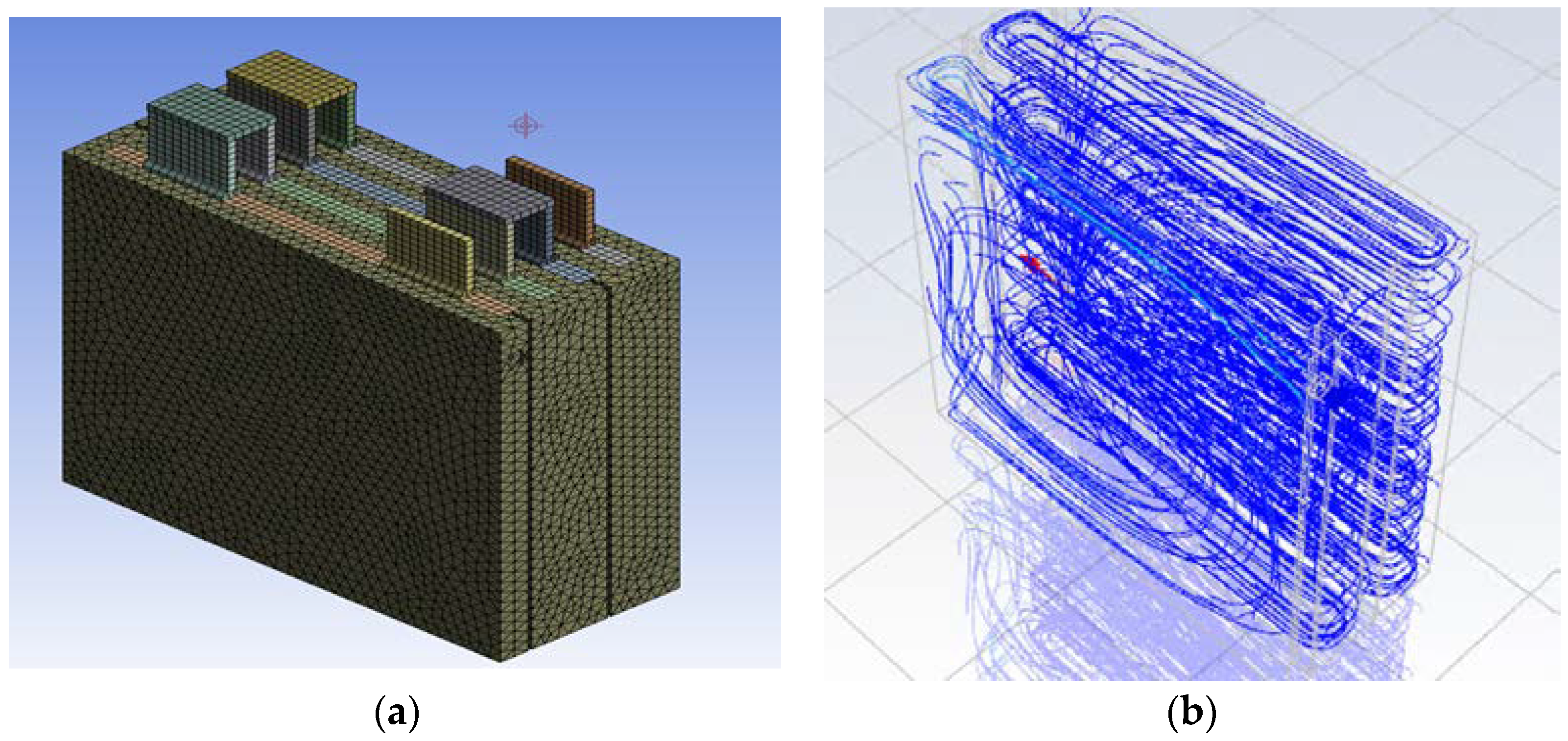
Figure 4 shows the final mesh for the BTMS (LIB module, enclosure, and coolant medium).

2.3. Input Parameters

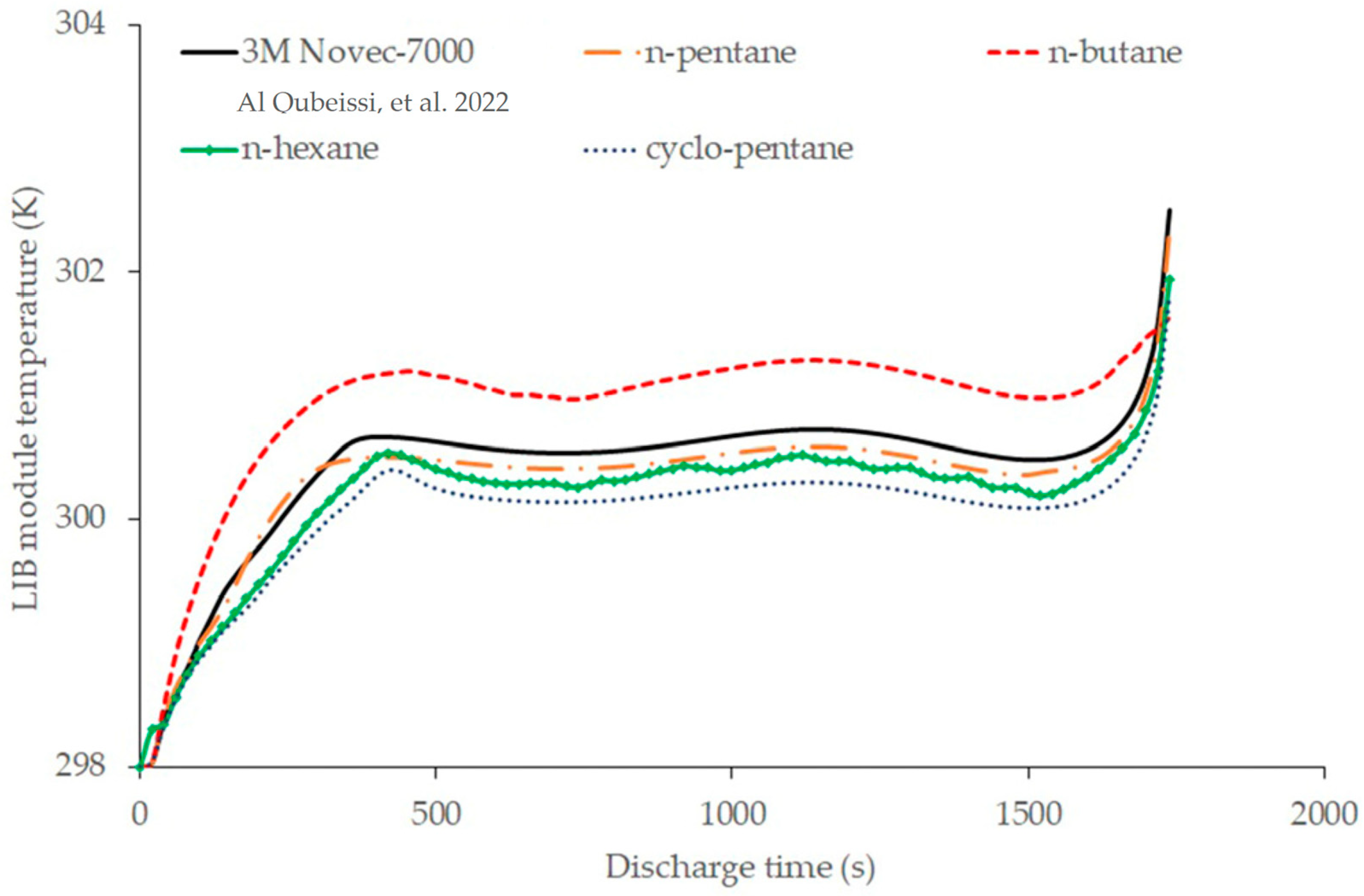
In this analysis, the dielectric fuel components (molecules) are utilised as the BTMS coolant. Only fuel components of a dielectric constant κ < 2 are considered in this model, avoiding any possible short circuit inside the LIB module. To validate the effectiveness of using fuel components as BTMS coolant, they are compared with the conventional coolant (3M Novec-7000).
The 3M Novec-7000 is a dielectric fluid, used for direct liquid cooling in HEV applications or electronic components, as discussed in the literature [22]. It has proven its efficiency in keeping LIBs within the optimal working temperature range at various discharge rates, and maintaining a uniform temperature distribution across the LIBs.
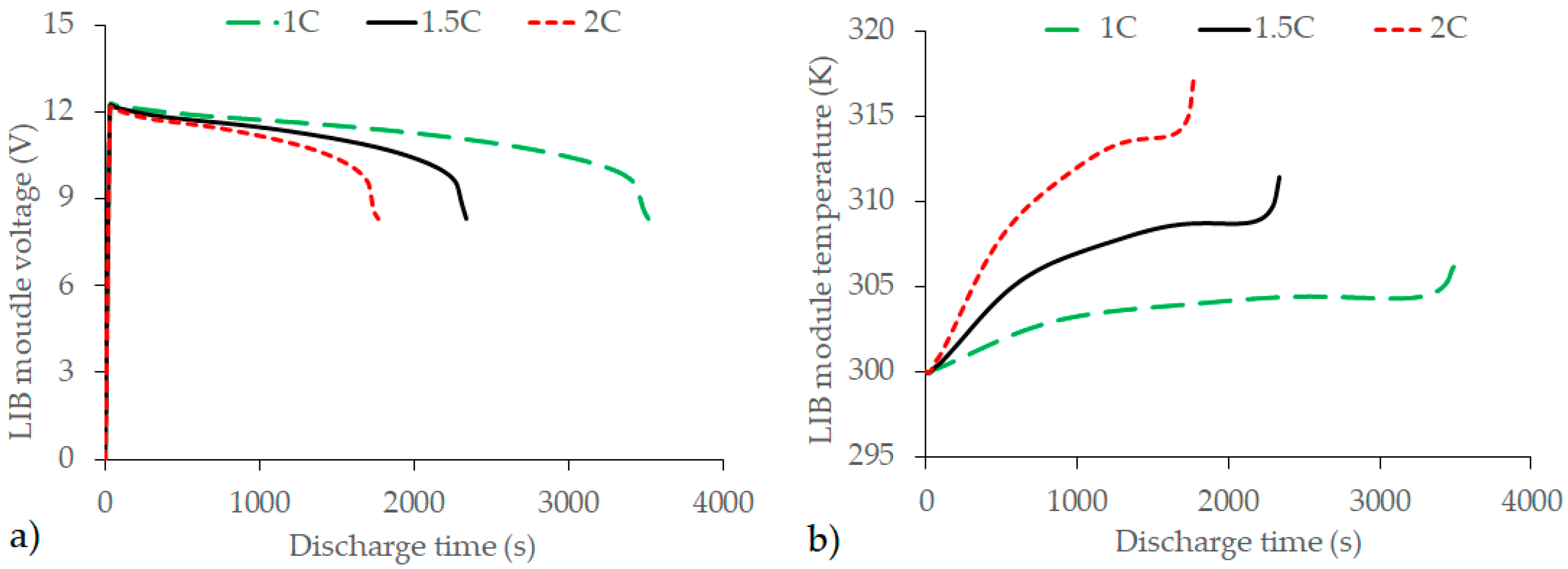
The cooling medium is set with inlet port temperature of 298 K and outlet port pressure of 1 atmospheric. The flow is simulated for three different inlet velocities: 0.1 m/s, 0.5 m/s, and 1 m/s, to understand the velocity influence on the thermal performance of the LIB module. Additionally, for each of the inlet velocities, three discharge rates are accounted for, 1C, 1.5C, and 2C. The transient discharge effects are considered in a quasi-steady format, with 30-time iterations until the LIB module is fully depleted. The free convection effect is included with the heat transfer coefficient set to 5 W/m2·K. The turbulence model (K-epsilon) is used for the CFD model, where the cooling medium inside the enclosure is expected to show some turbulent flow.
The properties of the proposed coolants are shown in Table 3. All fuel components have κ < 2 and reasonably good thermal conductivities, compared to the 3M Novec-7000. These fuel components will be further investigated for their suitability using ANSYS-fluent. In [35], the thermo-physical properties of different fuel components are provided with detailed methods of calculation, embedded in our model.

3. Results

The results are based on the main indicators for improving the BTMSs, in terms of temperature value and uniformity. The discharge rates, velocity and types of coolants are the controlling parameters in this study. In what follows, four types of petrol fuels are assessed for use as coolants and compared to the conventional coolants of 3M Novec-7000 and air (inferred from [37]).

3.1. N-Pentane

The temperature behaviour of the LIB module using N-Pentane as a coolant is shown in Table 4. When the inlet velocity is set to 0.1 m/s, the maximum LIB module temperature is maintained within the optimal operating range for all discharge rates, 1C (301.51 K), 1.5C (304.545 K), and 2C (306.534 K). In comparison with the free air convection (FAC)-BTMS results [33], it reduces the maximum temperature of the LIB module at 1C, 1.5C, and 2C by 2.6% (8.10 K), 2.2% (6.92 K), and 3.5% (10.99 K), respectively. When the inlet velocity of N-Pentane is increased to 0.5 m/s, the maximum LIB module temperatures are reduced by 2.5% (9.14 K), 4% (12.50 K), and 5.2% (16.37 K) for 1C, 1.5C, and 2C, respectively. At a higher inlet velocity (1 m/s), the maximum LIB module temperatures at 1C, 1.5C, and 2C are further reduced by 3.3% (10.12 K), 3.4% (10.63 K), and 5.9% (18.74 K), respectively. Since the temperature reduction between 0.5 m/s and 1 m/s is significant, passive control strategies can be implemented for such energy management by regulating the pump speed at high ambient temperatures.
The constant behaviours of the maximum LIB module temperature at all discharge rates are significantly improved compared to the inlet velocity of 0.1 m/s, which indicates that the inlet velocity is governed by the heat transfer process between the LIB module and to N-Pentane cooling medium, as shown in Figure 5. One can see that using N-Pentane as a BTMS liquid coolant (LC-BTMS) successfully maintains the LIB module temperature at a constant level within 80% of the total discharge time. This constant temperature behaviour can help to maintain the state of health of LIBs in the long run [10].
Figure 6 shows the temperature distribution of the LIB module and each of the LIBs. Even though the maximum LIB module temperature is below the maximum threshold value for all discharge rates and inlet velocities, at 2C and an inlet velocity of 0.1 m/s, the surface temperature difference of the LIB module is 146.3% (4.38 K) higher compared to FAC-BTMS. In terms of the maximum LIB temperature difference, N-Pentane also produces lower temperature differences (i.e., maintained homogenous thermal distribution) compared to FAC-BTMS at all discharge rates and inlet velocities. Between LIB 4 and LIB 1, the highest temperature difference is 2.24 K at the highest discharge rate (2C) and at an inlet velocity 1 m/s.

3.2. N-Hexane

At an inlet velocity of 0.1 m/s, N-Hexane LC-BTMS reduces the temperature of the maximum LIB module at 1C, 1.5C, and 2C by 2.7% (8.219 K), 2.3% (7.195 K), and 3.5% (11.262 K), respectively, compared to FAC-BTMS. From Table 5, the inlet velocity of 0.1 m/s is able to maintain the maximum LIB module temperature below 313 K for all discharge rates.
As can be seen from Table 5, the use of N-Hexane as LC-BTMS was useful in reducing the maximum LIB module temperature. For instance, at 0.5 m/s inlet velocity, the LIB module temperature is decreased by 3% at 1C, 4% at 1.5C, and 5.2% at 2C, compared to FAC-BTMS. As the inlet velocity is doubled to 1 m/s, further reductions in the maximum LIB module temperature are received as 3.1%, 3.5%, and 5.9%, lower than the case of FAC-BTMS, obtained at 1C, 1.5C, and 2C, respectively. As can see from the results, the temperature reductions for both 0.5 m/s and 1 m/s are similar. Therefore, to maintain low pumping power, the inlet velocity of 0.5 m/s can be sufficient to maintain the LIB module temperature within the safe range.
The LIB module temperatures at three inlet velocities versus discharge time are presented in Figure 7, based on the three discharge rates, (a) 1C, (b) 1.5C, and (c) 2C. As can be seen from the figure, the results show similar trends to those shown for N-Pentane LC-BTMS. The constant temperature behaviour occurs during the first 80% of the full discharge time.
The temperature contours of the LIB module are illustrated in Figure 8, showing all nine cases of discharge rates and inlet velocities, (a) 1C at 0.1 m/s, (b) 1.5C at 0.1 m/s, (c) 2C at 0.1 m/s, (d) 1.5C at 0.5 m/s, (e) 1.5C at 0.5 m/s, (f) 2C at 0.5 m/s, (g) 1C at 1 m/s, (h) 1.5C at 1 m/s, and (i) 2C at 1 m/s. For instance, at 0.1 m/s and 2C, the LIB module temperature is more homogenous than that of FAC-BTMS, with a 148.4% (4.416 K) less temperature difference. Although using N-Pentane as a coolant showed promising results, using N-Hexane as a coolant further reduced the temperature difference by almost 2.2 °C.

3.3. N-Butane

The BTMS using N-Butane is investigated and presented in Table 6. As can be seen from Table 6, using N-Butane as a coolant in BTMS, the temperature values and distribution are reasonably good. At an inlet velocity of 0.1 m/s, N-Butane LC-BTMS has a slightly better cooling performance than N-Heptane LC-BTMS at higher discharge rates. In comparison to FAC-BTMS, N-Butane decreases the maximum LIB module temperature by 2.0% (6.16 K), 2.5% (7.85 K), and 3.6% (11.57 K) at 1C, 1.5C, and 2C, respectively. When the inlet velocity of the cooling medium is increased to 0.5 m/s, the maximum LIB temperatures are decreased to 300.075K (at 1C), 302.217 K (at 1.5C), and 303.032 K (at 2C), which reduce the maximum temperature by 3.8% below the maximum threshold temperature (307 K). At 1 m/s, the maximum LIB module temperatures at 1C, 1.5C, and 2C are further reduced by 3.1% (9.60 K), 3.4% (10.88 K), and 5.9% (18.65 K), respectively. The temperature trends at both inlet velocities, 0.5 m/s and 1 m/s, are similar, especially at 1C and 1.5C; i.e., the pump speed can be reduced to maintain the same system efficiency. The temperatures versus discharge time for N-Butane are presented in Figure 9, which shows similar trends to those seen for other fuels. Nevertheless, the maximum LIB module temperatures tend to plateau for the first 80% of the full discharge time.
In terms of the temperature distribution of the LIB module and the comparison with FAC-BTMS, the maximum temperature difference still occurs at 2C and an inlet velocity of 0.1 m/s (higher by 125% or 4.00 K). This temperature difference, however, is slightly better than N-Heptane and N-Pentane LC-BTMS. The LIB module temperature distributions are shown in Figure 10.
In terms of the LIB temperature difference, N-Butane LC-BTMS produces the highest temperature difference of 2.922 K between LIB 4 and LIB 1. This temperature behaviour occurs at an inlet velocity of 0.1 m/s and a discharge rate of 1C, at a different parameter setting from those of N-Hexane and N-Pentane LC-BTMS.

3.4. Cyclo-Pentane

Compared to FAC-BTMS, Cyclo-Pentane LC-BTMS manages to reduce the maximum LIB module temperature by 2.6% (8.08 K), 2.3% (7.23 K), and 3.4% (10.85 K) at an inlet velocity of 0.1 m/s and 1C, 1.5C, and 2C, respectively. As shown in Table 7, the inlet velocity of 0.1 m/s is able to maintain the maximum LIB module temperature below 313 K for all discharge rates. When the inlet velocity of the cooling medium is increased to 0.5 m/s, the maximum LIB temperatures are reduced to 300.422 K (1C), 300.999 K (1.5C), and 301.822 K (2C), which provides the same average as N-Butane LC-BTMS, 3.8% below the maximum threshold temperature.
By doubling the inlet velocity of the cooling medium to 1 m/s, the maximum LIB module temperatures are further reduced to 299.74 K, 299.88 K, and 300.67 K at 1C, 1.5C, and 2C, respectively. These temperature reductions are not significant compared to the temperature at the inlet velocity of 0.5 m/s. Hence, it is recommended not to adopt a higher inlet velocity of more than 0.5 m/s for energy management strategy benefits. As shown in Figure 11, the maximum LIB module temperatures have a steady trend (more than 80% of the discharge time) for Cyclo-Pentane liquid-cooled at all discharge rates, which are similar to other fuel components.
The maximum temperature distribution of Cyclo-Pentane LC-BTMS is significantly poorer than that of other fuel components, with the highest temperature difference of 5.11 K at 0.1 m/s of inlet velocity and 2C. From Figure 12, the LIB cell temperature difference is also the highest compared to the other fuel components for LIB 4 and LIB 1, with a temperature difference of 4.138 K at an inlet velocity of 0.1 m/s and 2C.

3.5. Comparative Analysis

A comparative analysis is conducted to validate the performance of fuel components LC-BTMS against 3M Novec-7000 (conventional cooling medium) in the worst-case scenario at 2C and an inlet velocity of 0.5 m/s. As can be seen in Figure 13, all of the fuel components in the LC-BTMS system, with the exception of N-Butane LC-BTMS, have better cooling performance than the 3M Novec-7000 LC-BTMS. The results of this study suggest that the fuel component LC-BTMS has the potential as a cooling medium to maintain the temperature of LIB and can reduce the design complexity of BTMS. It is possible that integrating the fueling system and BTMS could help reduce vehicle weight and improve overall energy consumption.
To verify the accuracy of the CFD model, FAC-BTMS is compared with the previous work performed by [33]. Table 8 shows the LIB temperature behaviour of the module and cells at three discharge rates. As shown in Figure 14, 1C, 1.5C, and 2C require 3480 s, 2340 s, and 1740 s, respectively, to fully deplete the LIB module.
The maximum LIB module temperatures have the same values, 309.614 K, 311.464 K, and 317.526 K at 1C, 1.5C, and 2C, respectively. These results demonstrate that the CFD model is a valuable tool for evaluating the performance of fuel component LC-BTMS and can assist in the development of effective BTMS strategies.

4. Conclusions

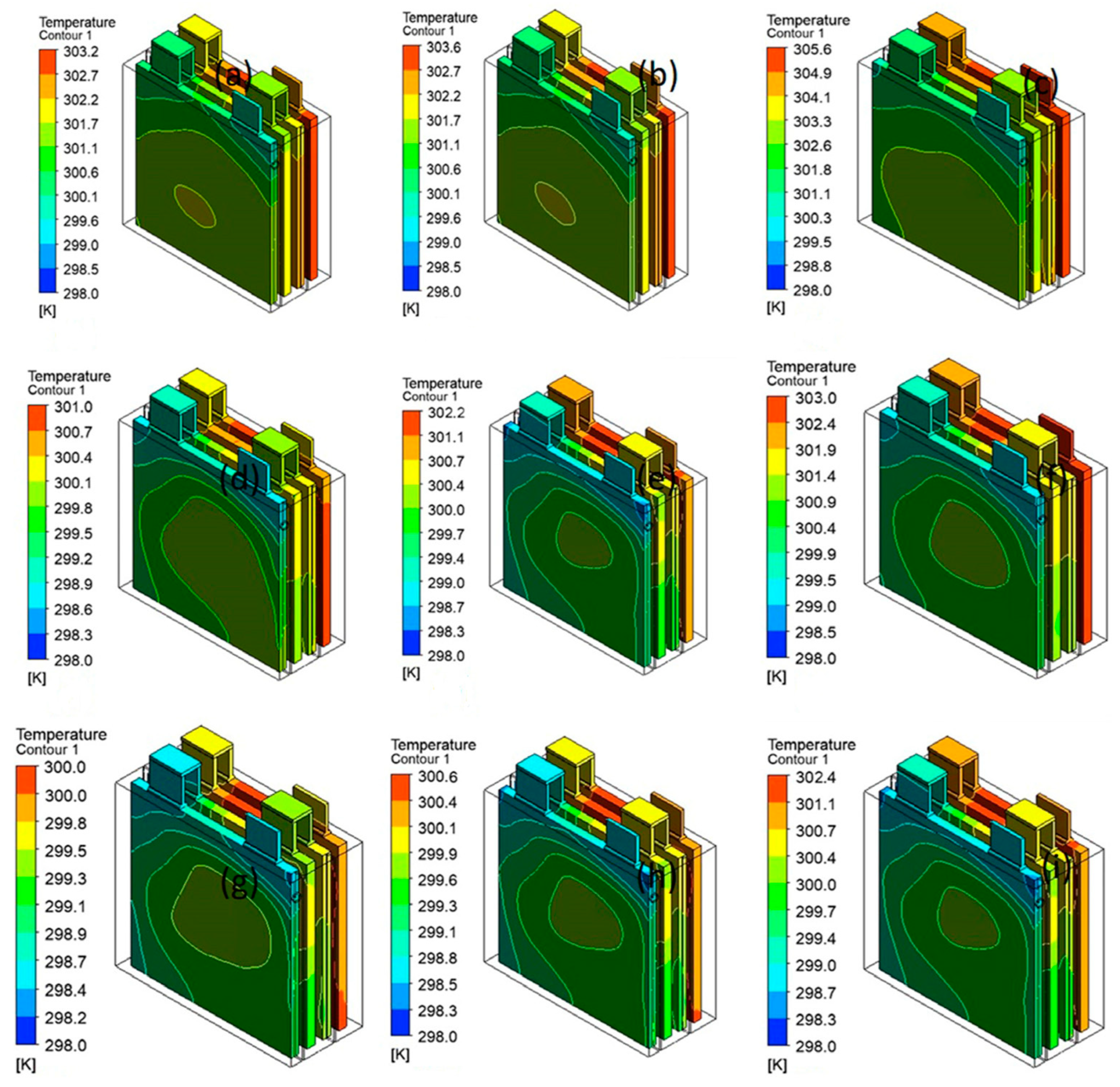
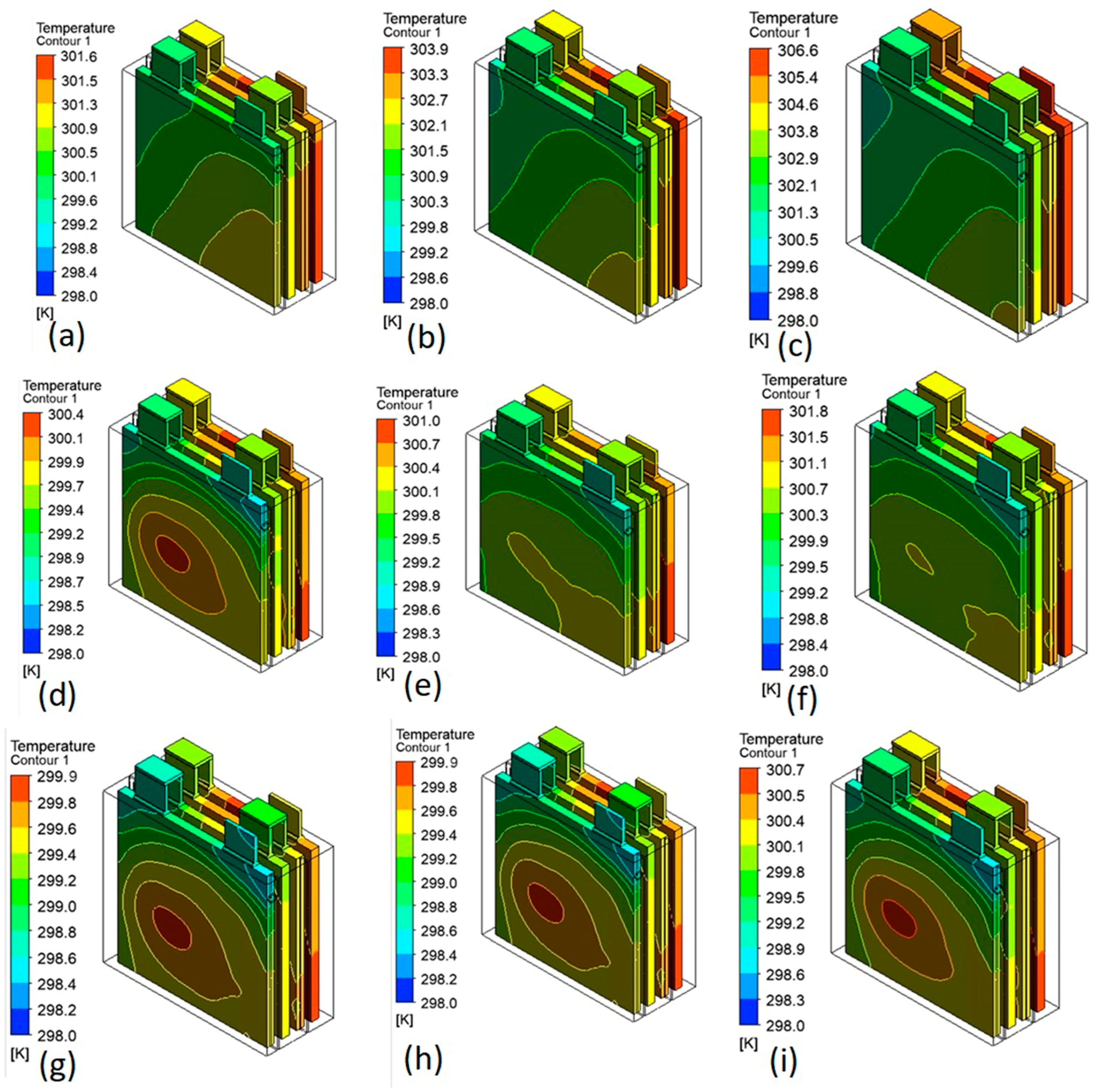
LIB module temperature without any cooling at the ambient condition of 298 K and 2C exceeds the maximum threshold temperature and can lead to thermal runaway. Hence, an efficient BTMS is required to maintain the optimal working temperature. Some fuel components, such as N-Pentane, N-Hexane, N-Butane, and Cyclo-Pentane, show the potential for coolants in direct cooling of LIB due to their dielectric constants (< 2). The cooling performance of fuel as LC-BTMS (liquid-coolant in battery thermal management system) in the HEVs application was successfully simulated using commercial CFD modelling, ANSYS-Fluent software. The CFD model shows a good agreement with the literature data and can be extended for different cooling media applications to characterise the thermal management of LIB modules.
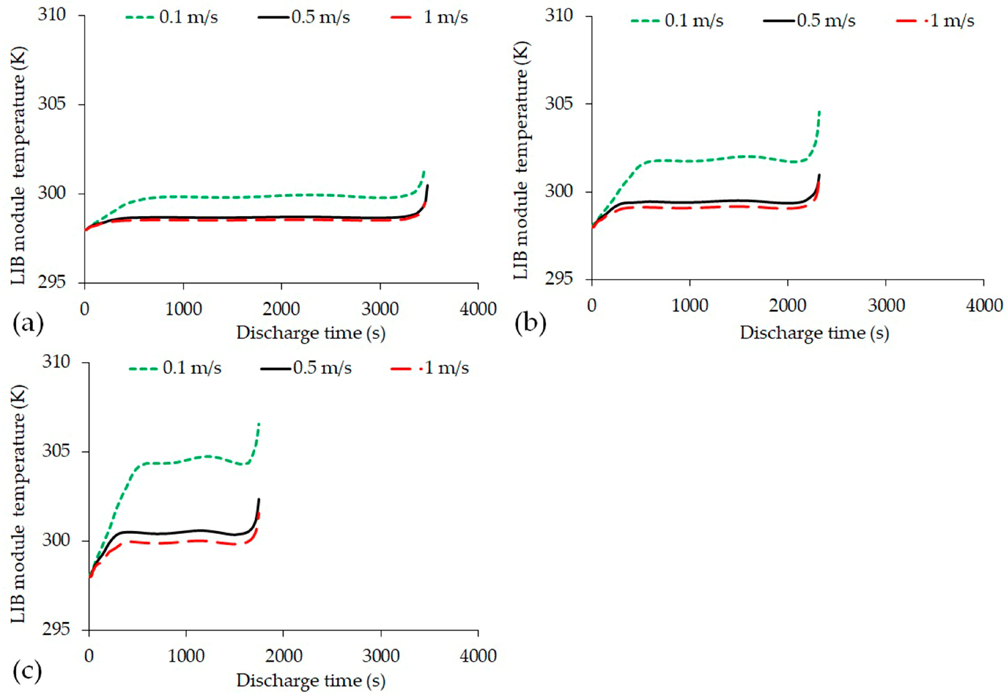
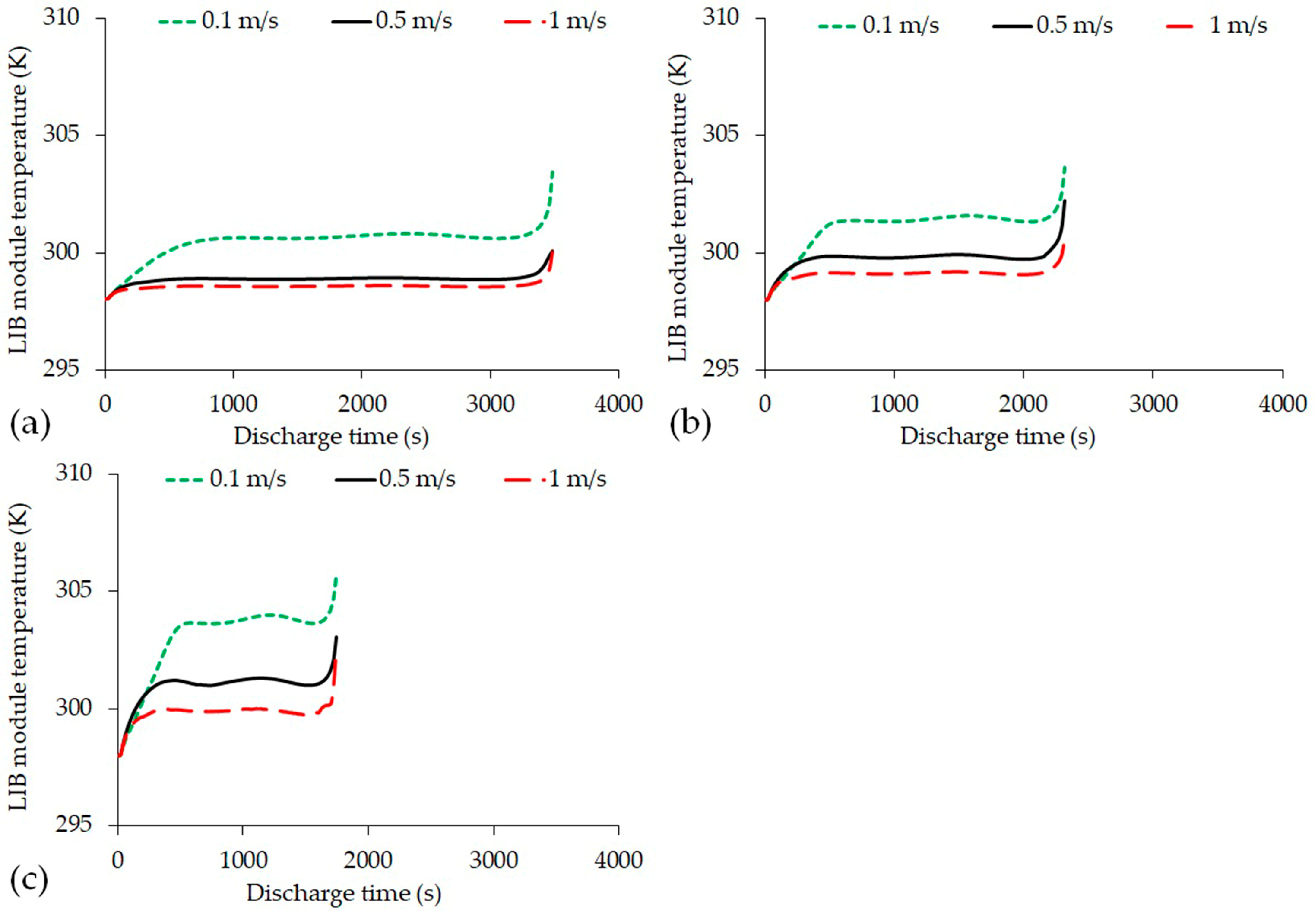
The results demonstrate that at all discharge rates, the maximum LIB module temperature is managed at:
  • 301.526 K (1C), 304.545 K (1.5), and 306.534 K (2C) for N-Pentane LC-BTMS at inlet velocity 0.1 m/s, indicating an average reduction of 2.8% compared to FAC-BTMS.
  • 299.497 K (1C), 300.834 K (1.5C), and 301.551 K(2C) for N-Pentane LC-BTMS at inlet velocity 1 m/s, indicating an average reduction of 3.9% compared to FAC-BTMS.;
  • 301.395 K (1C), 304.269 K (1.5), and 306.264 K (2C) for N-Hexane LC-BTMS at inlet velocity 0.1 m/s, indicating an average reduction of 2.8%.
  • 299.93 K (1C), 300.461 K (1.5C), and 301.399 K(2C) for N-Hexane LC-BTMS at inlet velocity 1 m/s, indicating an average reduction of 3.9%.
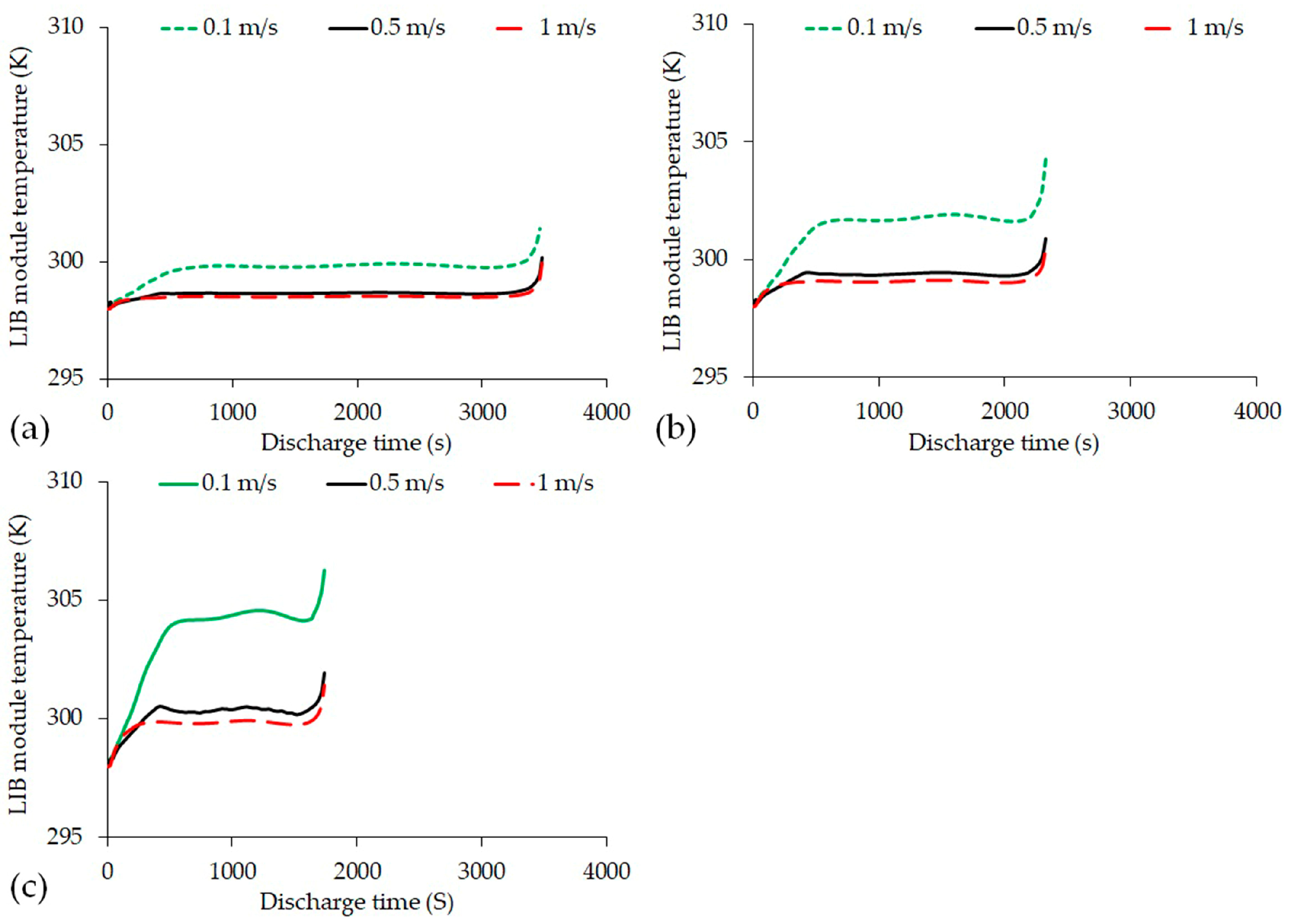
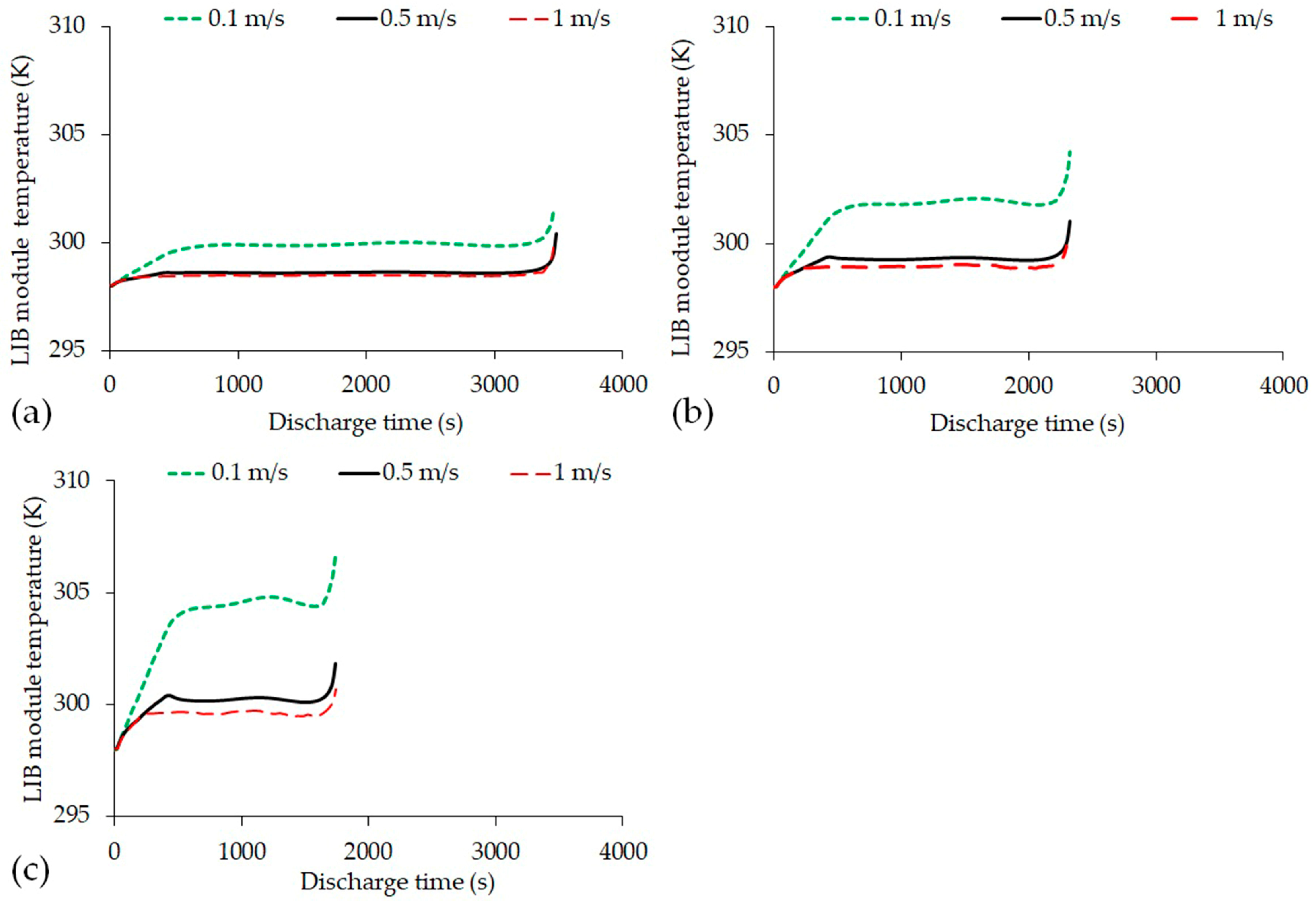
  • 303.456 K (1C), 303.611 K (1.5), and 305.957 K (2C) for N-Butane LC-BTMS at inlet velocity 0.1 m/s, indicating an average reduction of 2.7%.
  • 300.013 K (1C), 300.631 K (1.5C), and 302.575 K(2C) for N-Butane LC-BTMS at inlet velocity 1 m/s, indicating an average reduction of 3.8%.
  • 301.539 K (1C), 3304.236 K (1.5), and 306.674 K (2C) for Cyclo-Pentane LC-BTMS at inlet velocity 0.1 m/s, indicating an average reduction of 2.8%.
  • 299.736 K (1C), 299.879 K (1.5C), and 300.665 K(2C) for Cyclo-Pentane LC-BTMS at inlet velocity 1 m/s, with an average reduction of 4.1%.compared to FAC-BTMSs.
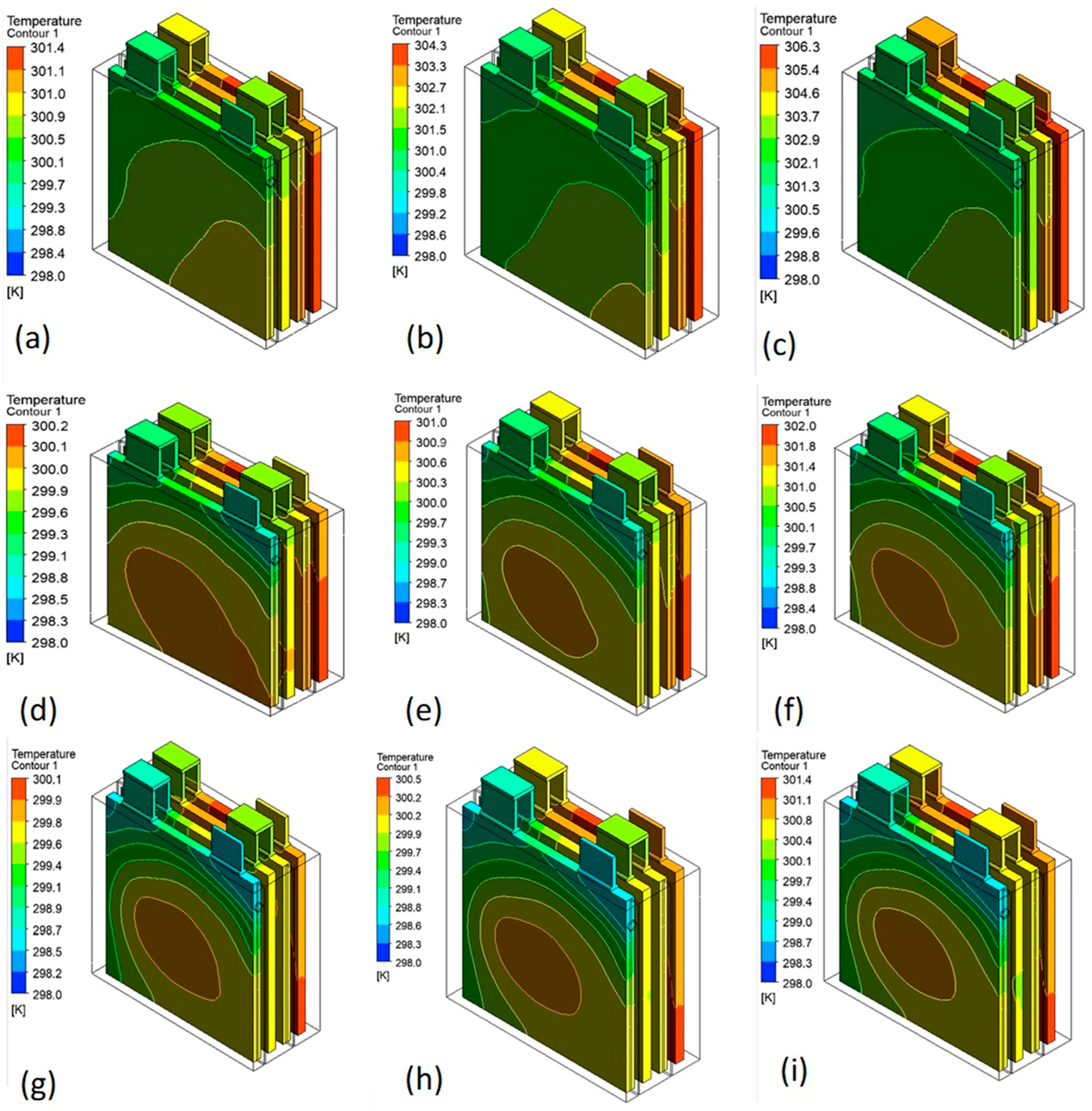
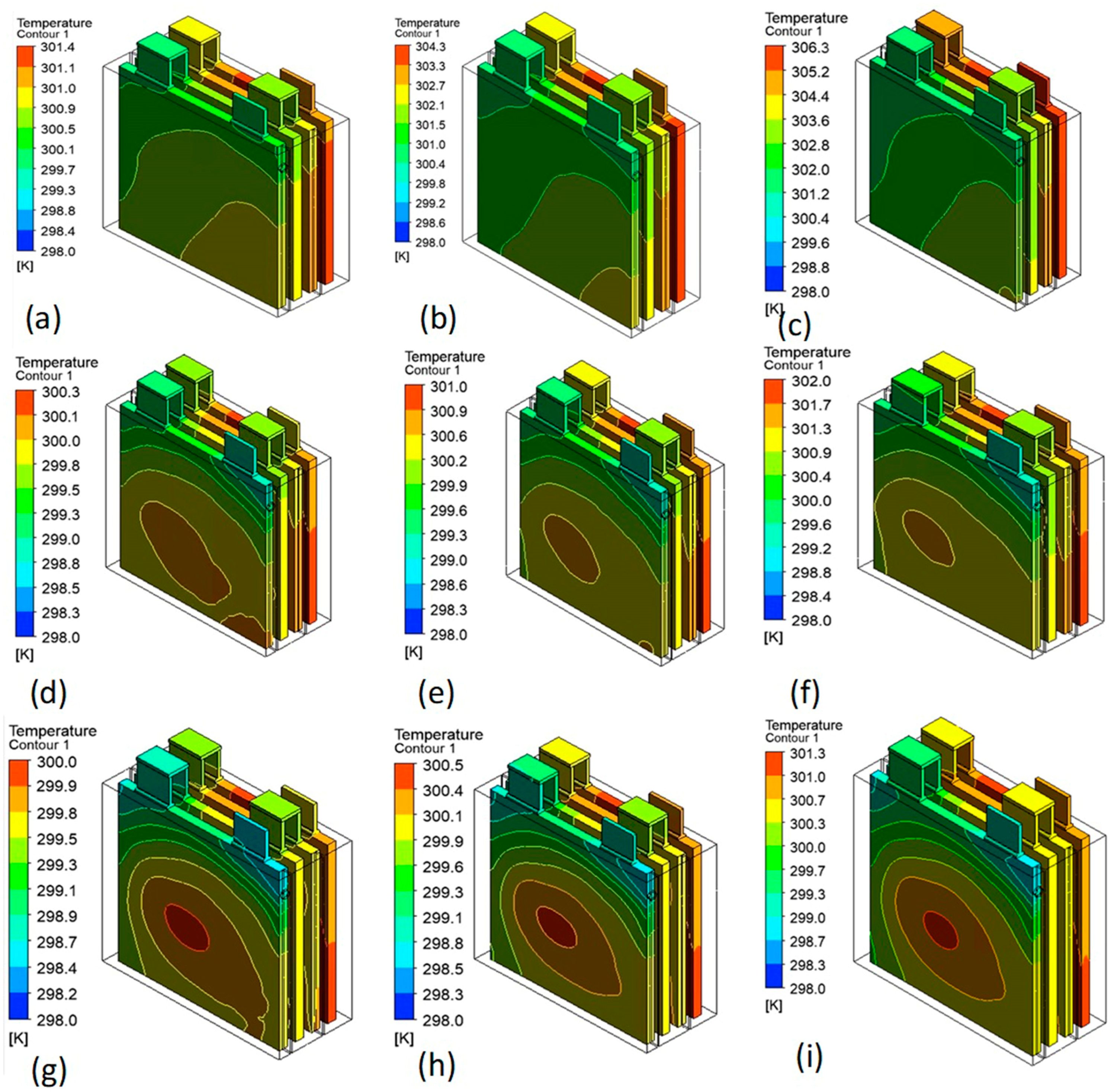
Also, it is noted that N-Pentane, N-Hexane, N-Butane, and Cyclo-Pentane produce an average temperature difference of −0.101 K, −0.232 K, 0.490 K, and −0.380 K, respectively, below that of 3M Novec-7000 LC-BTMS. Additionally, all fuel component LC-BTMSs are able to maintain the temperature difference between LIB cells below 5 K.
To conclude, the relatively low density of these fuel components can help in reducing the overall mass of the vehicle and improve its energy consumption which makes these fuel components viable alternatives to conventional cooling media. It is important to note the flammability of fuels when used in BTMSs. As such, indirect cooling can be more feasible in practice, when the temperature range exceeds the advised temperature limited in this research finding.

Author Contributions

Conceptualisation, M.A.Q.; data curation, R.M.R.A.S.; investigation, H.Y.; project administration, M.A.Q. and H.S.S.; resources, M.A.Q. and R.M.R.A.S.; software, M.A.Q. and H.Y.; supervision, M.A.Q. and R.M.R.A.S.; writing—original draft, H.Y., R.M.R.A.S. and M.A.Q.; writing—review and editing, M.A.Q. and R.M.R.A.S. All authors have read and agreed to the published version of the manuscript.

Funding

This research received no external funding.

Institutional Review Board Statement

Not applicable.

Informed Consent Statement

Not applicable.

Data Availability Statement

Data is unavailable due to privacy and link to the continuing study.

Conflicts of Interest

The authors declare no conflict of interest.

References

  1. Nickischer, A. Environmental Impacts of Internal Combustion Engines and Electric Battery Vehicles. DU Quark 2020, 4, 21–31. [Google Scholar]
  2. Xia, G.; Cao, L.; Bi, G. A Review on Battery Thermal Management in Electric Vehicle Application. J. Power Source 2017, 367, 90–105. [Google Scholar] [CrossRef]
  3. Shah, R.M.R.A.; McGordon, A.; Rahman, M.M.; Amor-Segan, M.; Jennings, P. Characterisation of Micro Turbine Generator as a Range Extender Using an Automotive Drive Cycle for Series Hybrid Electric Vehicle Application. Appl. Therm. Eng. 2021, 184, 116302. [Google Scholar] [CrossRef]
  4. Sawant, S.; Shah, R.M.R.A.; Rahman, M.; Smith, S.; Jumahat, A. System Modelling of an Electric Two-Wheeled Vehicle for Energy Management Optimization Study; Collections; Kyushu University Library: Fukuoka, Japan, 2021. [Google Scholar]
  5. Funke, S.Á.; Sprei, F.; Gnann, T.; Plötz, P. How Much Charging Infrastructure Do Electric Vehicles Need? A Review of the Evidence and International Comparison. Transp. Res. Part D Transp. Environ. 2019, 77, 224–242. [Google Scholar] [CrossRef]
  6. Shah, R.M.R.A.; Qubeissi, M.A.; McGordon, A.; Amor-Segan, M.; Jennings, P. Micro Gas Turbine Range Extender Performance Analysis Using Varying Intake Temperature. Automot. Innov. 2020, 3, 356–365. [Google Scholar] [CrossRef]
  7. Ma, S.; Jiang, M.; Tao, P.; Song, C.; Wu, J.; Wang, J.; Deng, T.; Shang, W. Temperature Effect and Thermal Impact in Lithium-Ion Batteries: A Review. Prog. Nat. Sci. Mater. Int. 2018, 28, 653–666. [Google Scholar] [CrossRef]
  8. Sato, N. Thermal Behavior Analysis of Lithium-Ion Batteries for Electric and Hybrid Vehicles. J. Power Source 2001, 99, 70–77. [Google Scholar] [CrossRef]
  9. Peng, X.; Cui, X.; Liao, X.; Garg, A. A Thermal Investigation and Optimization of an Air-Cooled Lithium-Ion Battery Pack. Energies 2020, 13, 2956. [Google Scholar] [CrossRef]
  10. Lyu, Y.; Siddique, A.R.M.; Majid, S.H.; Biglarbegian, M.; Gadsden, S.A.; Mahmud, S. Electric Vehicle Battery Thermal Management System with Thermoelectric Cooling. Energy Rep. 2019, 5, 822–827. [Google Scholar] [CrossRef]
  11. Liu, H.; Wei, Z.; He, W.; Zhao, J. Thermal Issues about Li-Ion Batteries and Recent Progress in Battery Thermal Management Systems: A Review. Energy Convers. Manag. 2017, 150, 304–330. [Google Scholar] [CrossRef]
  12. Kim, T.; Song, W.; Son, D.-Y.; Ono, L.K.; Qi, Y. Lithium-Ion Batteries: Outlook on Present, Future, and Hybridized Technologies. J. Mater. Chem. A 2019, 7, 2942–2964. [Google Scholar] [CrossRef]
  13. Bai, Y.; Li, L.; Li, Y.; Chen, G.; Zhao, H.; Wang, Z.; Wu, C.; Ma, H.; Wang, X.; Cui, H.; et al. Reversible and Irreversible Heat Generation of NCA/Si–C Pouch Cell during Electrochemical Energy-Storage Process. J. Energy Chem. 2019, 29, 95–102. [Google Scholar] [CrossRef] [Green Version]
  14. On-Line Scheme for Parameter Estimation of Nonlinear Lithium Ion Battery Equivalent Circuit Models Using the Simplified Refined Instrumental Variable Method for a Modified Wiener Continuous-Time Model—ScienceDirect. Available online: https://www.sciencedirect.com/science/article/pii/S0306261917308991?via%3Dihub (accessed on 25 October 2022).
  15. Review—Reversible Heat Effects in Cells Relevant for Lithium-Ion Batteries—IOPscience. Available online: https://iopscience.iop.org/article/10.1149/1945-7111/abfd73 (accessed on 25 October 2022).
  16. Wang, Q.; Ping, P.; Zhao, X.; Chu, G.; Sun, J.; Chen, C. Thermal Runaway Caused Fire and Explosion of Lithium Ion Battery. J. Power Source 2012, 208, 210–224. [Google Scholar] [CrossRef]
  17. An, Z.; Jia, L.; Ding, Y.; Dang, C.; Li, X. A Review on Lithium-Ion Power Battery Thermal Management Technologies and Thermal Safety. J. Therm. Sci. 2017, 26, 391–412. [Google Scholar] [CrossRef]
  18. Luo, J.; Zou, D.; Wang, Y.; Wang, S.; Huang, L. Battery Thermal Management Systems (BTMs) Based on Phase Change Material (PCM): A Comprehensive Review. Chem. Eng. J. 2022, 430, 132741. [Google Scholar] [CrossRef]
  19. Lin, J.; Liu, X.; Li, S.; Zhang, C.; Yang, S. A Review on Recent Progress, Challenges and Perspective of Battery Thermal Management System. Int. J. Heat Mass Transf. 2021, 167, 120834. [Google Scholar] [CrossRef]
  20. Zhao, C.; Zhang, B.; Zheng, Y.; Huang, S.; Yan, T.; Liu, X. Hybrid Battery Thermal Management System in Electrical Vehicles: A Review. Energies 2020, 13, 6257. [Google Scholar] [CrossRef]
  21. Tan, X.; Lyu, P.; Fan, Y.; Rao, J.; Ouyang, K. Numerical Investigation of the Direct Liquid Cooling of a Fast-Charging Lithium-Ion Battery Pack in Hydrofluoroether. Appl. Therm. Eng. 2021, 196, 117279. [Google Scholar] [CrossRef]
  22. Thakur, A.K.; Prabakaran, R.; Elkadeem, M.R.; Sharshir, S.W.; Arıcı, M.; Wang, C.; Zhao, W.; Hwang, J.-Y.; Saidur, R. A State of Art Review and Future Viewpoint on Advance Cooling Techniques for Lithium–Ion Battery System of Electric Vehicles. J. Energy Storage 2020, 32, 101771. [Google Scholar] [CrossRef]
  23. Chen, D.; Jiang, J.; Kim, G.-H.; Yang, C.; Pesaran, A. Comparison of Different Cooling Methods for Lithium Ion Battery Cells. Appl. Therm. Eng. 2016, 94, 846–854. [Google Scholar] [CrossRef] [Green Version]
  24. Pesaran, A. Battery Thermal Management in EVs and HEVs: Issues and Solutions. Battery Man 2001, 43, 34–49. [Google Scholar]
  25. Akbarzadeh, M.; Kalogiannis, T.; Jaguemont, J.; Jin, L.; Behi, H.; Karimi, D.; Beheshti, H.; Van Mierlo, J.; Berecibar, M. A Comparative Study between Air Cooling and Liquid Cooling Thermal Management Systems for a High-Energy Lithium-Ion Battery Module. Appl. Therm. Eng. 2021, 198, 117503. [Google Scholar] [CrossRef]
  26. Kim, J.; Oh, J.; Lee, H. Review on Battery Thermal Management System for Electric Vehicles. Appl. Therm. Eng. 2019, 149, 192–212. [Google Scholar] [CrossRef]
  27. Noël, J.A.; Kahwaji, S.; Desgrosseilliers, L.; Groulx, D.; White, M.A. 22—Phase Change Materials. In Storing Energy, 2nd ed.; Letcher, T.M., Ed.; Elsevier: Amsterdam, The Netherlands, 2022; pp. 503–535. ISBN 978-0-12-824510-1. [Google Scholar]
  28. Wang, Y.; Wang, Z.; Min, H.; Li, H.; Li, Q. Performance Investigation of a Passive Battery Thermal Management System Applied with Phase Change Material. J. Energy Storage 2021, 35, 102279. [Google Scholar] [CrossRef]
  29. Buidin, T.I.C.; Mariasiu, F. Battery Thermal Management Systems: Current Status and Design Approach of Cooling Technologies. Energies 2021, 14, 4879. [Google Scholar] [CrossRef]
  30. Mbulu, H.; Laoonual, Y.; Wongwises, S. Experimental Study on the Thermal Performance of a Battery Thermal Management System Using Heat Pipes. Case Stud. Therm. Eng. 2021, 26, 101029. [Google Scholar] [CrossRef]
  31. Nasir, F.; Abdullah, M.Z.; Ismail, M. Experimental Investigation on the Heat Transfer Performance of Heat Pipes in Cooling Hev Lithium-Ion Batteries. Heat Transf. Res. 2018, 49, 1745–1760. [Google Scholar] [CrossRef]
  32. Wang, R.; Liang, Z.; Souri, M.; Esfahani, M.N.; Jabbari, M. Numerical Analysis of Lithium-Ion Battery Thermal Management System Using Phase Change Material Assisted by Liquid Cooling Method. Int. J. Heat Mass Transf. 2022, 183, 122095. [Google Scholar] [CrossRef]
  33. Al Qubeissi, M.; Almshahy, A.; Mahmoud, A.; Al-Asadi, M.T.; Raja Ahsan Shah, R.M. Modelling of Battery Thermal Management: A New Concept of Cooling Using Fuel. Fuel 2022, 310, 122403. [Google Scholar] [CrossRef]
  34. Dielectric Constant. Available online: https://macro.lsu.edu/howto/solvents/Dielectric%20Constant%20.htm (accessed on 12 July 2022).
  35. Al Qubeissi, M.; Sazhin, S.S.; Turner, J.; Begg, S.; Crua, C.; Heikal, M.R. Modelling of Gasoline Fuel Droplets Heating and Evaporation. Fuel 2015, 159, 373–384. [Google Scholar] [CrossRef] [Green Version]
  36. Liquids and Fluids—Specific Heats. Available online: https://www.engineeringtoolbox.com/specific-heat-fluids-d_151.html (accessed on 12 July 2022).
  37. Al Qubeissi, M.; Mahmoud, A.; Al-Damook, M.; Almshahy, A.; Khatir, Z.; Soyhan, H.S.; Raja Ahsan Shah, R.M. Comparative Analysis of Battery Thermal Management System Using Biodiesel Fuels. Energies 2023, 16, 565. [Google Scholar] [CrossRef]
Figure 1. LIB module 4S1P design with busbar and tab with third angle projection view (a) isometric view, (b) plan view, (c) side view, and (d) front view.
Sustainability 15 05868 g001
Figure 2. LIB module enclosure design for cooling medium inlet and outlet, in (a) isometric view and (b) top view.
Sustainability 15 05868 g002
Figure 3. LIB module maximum temperature versus element size, showing the mesh independence check.
Sustainability 15 05868 g003
Figure 4. LIB module and LIB module enclosure of (a) complete mesh and (b) flow field of cooling medium.
Sustainability 15 05868 g004
Figure 5. LIB module temperature with N-Pentane LC-BTMS at three inlet velocities (a) 1C, (b) 1.5C, and (c) 2C.
Sustainability 15 05868 g005
Figure 6. LIB module temperature distribution with N-Pentane LC-BTMS at (a) 1C at 0.1 m/s, (b) 1.5C at 0.1 m/s, (c) 2C at 0.1 m/s, (d) 1.5C at 0.5 m/s, (e) 1.5C at 0.5 m/s, (f) 2C at 0.5 m/s, (g) 1C at 1 m/s, (h) 1.5C at 1 m/s, and (i) 2C at 1 m/s.
Sustainability 15 05868 g006
Figure 7. LIB module temperature with N-Hexane liquid-cooled BTMS at three inlet velocities (a) 1C, (b) 1.5C, and (c) 2C.
Sustainability 15 05868 g007
Figure 8. LIB module temperature distribution with N-Hexane LC-BTMS at (a) 1C at 0.1 m/s, (b) 1.5C at 0.1 m/s, (c) 2C at 0.1 m/s, (d) 1.5C at 0.5 m/s, (e) 1.5C at 0.5 m/s, (f) 2C at 0.5 m/s, (g) 1C at 1 m/s, (h) 1.5C at 1 m/s, and (i) 2C at 1 m/s.
Sustainability 15 05868 g008
Figure 9. LIB module temperature with N-Butane LC-BTMS at three inlet velocities (a) 1C, (b) 1.5C, and (c) 2C.
Sustainability 15 05868 g009
Figure 10. LIB module temperature distribution with N-Butane LC-BTMS at (a) 1C at 0.1 m/s, (b) 1.5C at 0.1 m/s, (c) 2C at 0.1 m/s, (d) 1.5C at 0.5 m/s, (e) 1.5C at 0.5 m/s, (f) 2C at 0.5 m/s, (g) 1C at 1 m/s, (h) 1.5C at 1 m/s, and (i) 2C at 1 m/s.
Sustainability 15 05868 g010
Figure 11. LIB module temperature with Cyclo-Pentane liquid-cooled BTMS at three inlet velocities (a) 1C, (b) 1.5C, and (c) 2C.
Sustainability 15 05868 g011
Figure 12. LIB module temperature distribution with Cyclo-Pentane LC-BTMS at (a) 1C at 0.1 m/s, (b) 1.5C at 0.1 m/s, (c) 2C at 0.1 m/s, (d) 1.5C at 0.5 m/s, (e) 1.5C at 0.5 m/s, (f) 2C at 0.5 m/s, (g) 1C at 1 m/s, (h) 1.5C at 1 m/s, and (i) 2C at 1 m/s.
Sustainability 15 05868 g012
Figure 13. Comparative analysis of LC-BTMS, fuel components vs. 3M Novec-7000 [33] at 2C and an inlet velocity of 0.5 m/s.
Sustainability 15 05868 g013
Figure 14. LIB module behaviour at three discharge rates with FAC-BTMS (a) LIB module voltage and (b) LIB module temperature.
Sustainability 15 05868 g014
Table 1. LIB specifications.
ParametersValue
Nominal capacity (A·h)14
Max discharge rate (C)2
Min discharge rate (C)1
Max module voltage (V)12
Min module voltage (V)8.1
Height (mm)100
Width (mm)100
Thickness (mm)5
Density kg·m32092
Specific heat (J/kg·K)678
Thermal conductivity (W/m·K)18.2
Table 2. Tab and busbar properties.
PropertiesTabBusbar
MaterialAluminumCopper
Density (kg/m3)27198978
Specific heat (J/kg·K)871381
Thermal conductivity (W/m·K)2022.4387.6
Table 3. Comparison of thermo-physical properties of fuel components, and 3M Novec-7000 [34,36].
Cooling MediumDensity (kg·m3)Constant Specific Heat (J/kg·K)Thermal Conductivity (W/m·K)Viscosity (kg/m·s)κ
N-Pentane62223300.1050.00021401.84
N-Hexane65322600.1140.00029701.88
N-Butane58116750.0950.00000741.77
Cyclo-Pentane76317570.1700.00046221.97
3M Novec-7000 140013000.0750.00045007.40
Table 4. Temperature behaviour of the LIB module with N-Pentane LC-BTMS.
LIB Type1C1.5C2C
Tmax (K)Tmin (K)Tmax (K)Tmin (K)Tmax (K)Tmin (K)
Cooling medium velocity = 0.1 m/s
Module301.516299.753304.545301.437306.534302.154
LIB 1300.729299.753303.243301.437304.292302.154
LIB 2300.81300.014303.39301.813304.545302.899
LIB 3301.263300.636304.132302.907305.723304.553
LIB 4301.516301.008304.545303.557306.534305.605
Cooling medium velocity = 0.5 m/s
Module300.478298.83300.981298.963302.346299.378
LIB 1300.149298.83300.529298.963301.59299.378
LIB 2300.178299.134300.558299.348301.66299.942
LIB 3300.305299.771300.742300.33301.956301.413
LIB 4300.478299.974300.981300.627302.346301.862
Cooling medium velocity = 1 m/s
Module299.497298.335300.834298.648301.551298.788
LIB 1299.306298.335300.472298.648301.023298.788
LIB 2299.336298.455300.545298.873301.107299.073
LIB 3299.398299.107300.659300.111301.302300.572
LIB 4299.497299.21300.834300.296301.551300.818
Table 5. Temperature behaviour of the LIB module with N-Hexane LC-BTMS.
LIB Type1C 1.5C 2C
Tmax (K)Tmin (K)Tmax (K)Tmin (K)Tmax (K)Tmin (K)
Cooling velocity = 0.1 m/s
Module301.395299.630304.269301.169306.264301.848
LIB 1300.636299.630302.992301.169304.058301.848
LIB 2300.716299.937303.143301.632304.312302.709
LIB 3301.154300.570303.869302.752305.453304.391
LIB 4301.395300.921304.269303.369306.264305.388
Cooling velocity = 0.5 m/s
Module300.167298.762300.88298.993301.932299.320
LIB 1299.789298.762300.342298.993301.077299.320
LIB 2299.837299.067300.408299.415301.17299.902
LIB 3300.003299.567300.641300.224301.534301.104
LIB 4300.167299.764300.88300.522301.932301.518
Cooling velocity = 1 m/s
Module299.930298.494300.461298.61301.399298.817
LIB 1299.713298.494300.153298.61300.871298.817
LIB 2299.708298.676300.137298.849300.863299.149
LIB 3299.817299.45300.293299.905301.154300.573
LIB 4299.93299.576300.461300.049301.399300.790
Table 6. Temperature behaviour of the LIB module with N-Butane LC-BTMS.
LIB Type1C1.5C2C
Tmax (K)Tmin (K)Tmax (K)Tmin (K)Tmax (K)Tmin (K)
Cooling velocity = 0.1 m/s
Module303.456300.15303.611300.975305.957301.957
LIB 1301.647300.15302.211300.975303.522301.957
LIB 2302.19300.586302.349301.355303.731302.626
LIB 3302.914301.926303.104302.164304.857303.854
LIB 4303.456302.396303.611302.823305.753304.879
Cooling velocity = 0.5 m/s
Module300.075298.474302.217299.042303.032299.112
LIB 1299.338298.474300.924299.042301.202299.112
LIB 2299.685298.545301.507299.190301.923299.283
LIB 3299.901299.275301.923300.742302.574301.023
LIB 4300.075299.607302.217301.348303.032301.830
Cooling velocity = 1 m/s
Module300.013298.383300.631298.483302.575298.877
LIB 1299.372298.393299.703298.483301.118298.877
LIB 2299.711298.456300.212298.562301.841299.02
LIB 3299.901299.148300.457299.409302.309300.592
LIB 4300.013299.464300.631299.826302.575301.316
Table 7. Temperature behaviour of the LIB module with Cyclo-Pentane LC-BTMS.
LIB Type1C1.5C2C
Tmax (K)Tmin (K)Tmax (K)Tmin (K)Tmax (K)Tmin (K)
Cooling velocity = 0.1 m/s
Module301.539299.525304.236300.736306.674301.561
LIB 1300.8299.525302.947300.736304.537301.561
LIB 2300.898299.934303.131301.464304.841302.783
LIB 3301.33300.670303.870302.784306.005304.783
LIB 4301.539300.986304.236303.345306.674305.699
Cooling velocity = 0.5 m/s
Module300.422298.816300.999298.983301.822299.243
LIB 1299.825298.816300.188298.983300.736299.2243
LIB 2299.920299.178300.323299.452300.922299.860
LIB 3300.187299.591300.681300.127301.399300.856
LIB 4300.422299.841300.999300.489301.822301.36
Cooling velocity = 1 m/s
Module299.736298.444299.879298.462300.665298.644
LIB 1299.498298.444299.585298.462300.189298.644
LIB 2299.474298.637299.548298.68300.144298.951
LIB 3299.592299.262299.701299.441300.432299.999
LIB 4299.736299.416299.879299.604300.665300.234
Table 8. Maximum and minimum temperatures of the LIB module with FAC-BTMS.
LIB Type1C1.5C2C
Tmax (K)Tmin (K)Tmax (K)Tmin (K)Tmax (K)Tmin (K)
Module309.614307.208311.464310.261317.526315.748
LIB 1309.614307.568311.464310.428317.526316.006
Lib 2309.587307.551311.436310.422317.481315.997
LIB 3309.587308.55311.436310.422317.481315.997
LIB 4309.614307.568311.464310.428317.526316.006
Disclaimer/Publisher’s Note: The statements, opinions and data contained in all publications are solely those of the individual author(s) and contributor(s) and not of MDPI and/or the editor(s). MDPI and/or the editor(s) disclaim responsibility for any injury to people or property resulting from any ideas, methods, instructions or products referred to in the content.

