
Mechanical Behavior of Hydrated-Lime–Liquid-Stabilizer-Treated Granular Lateritic Soils


Abstract
:1. Introduction
2. Materials and Methods
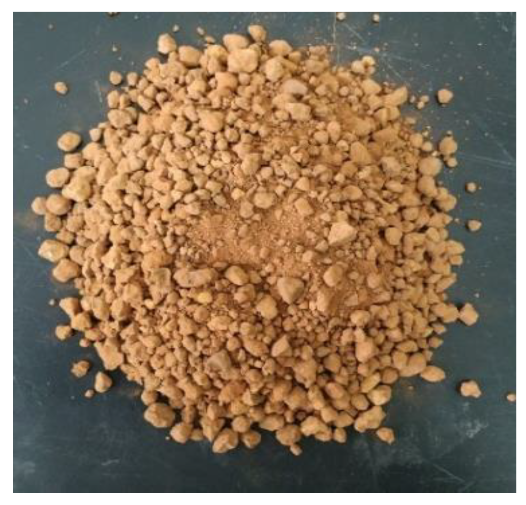
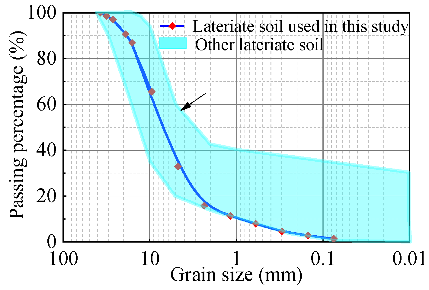
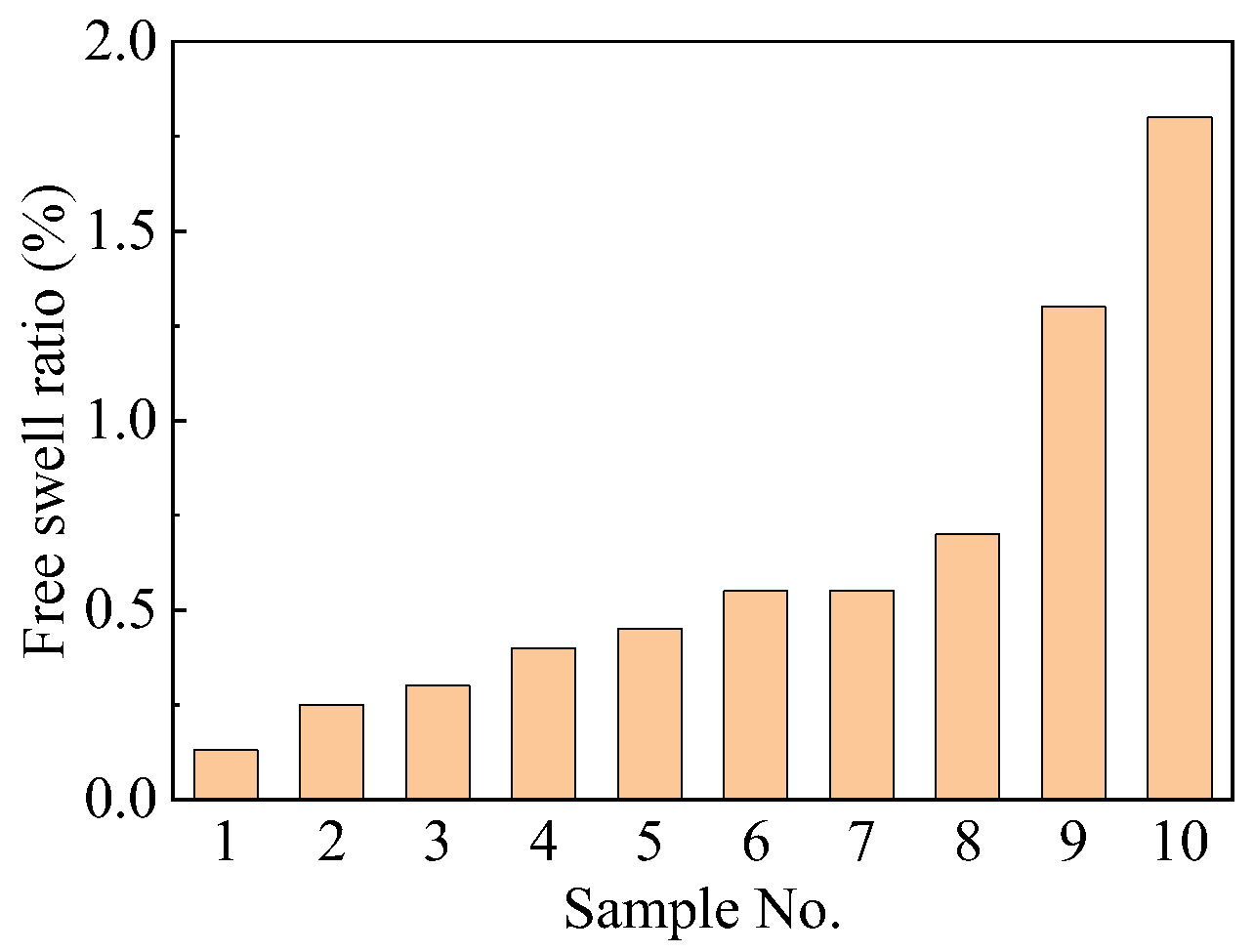
2.1. Materials
2.2. Specimen Preparation
2.3. Test Methods
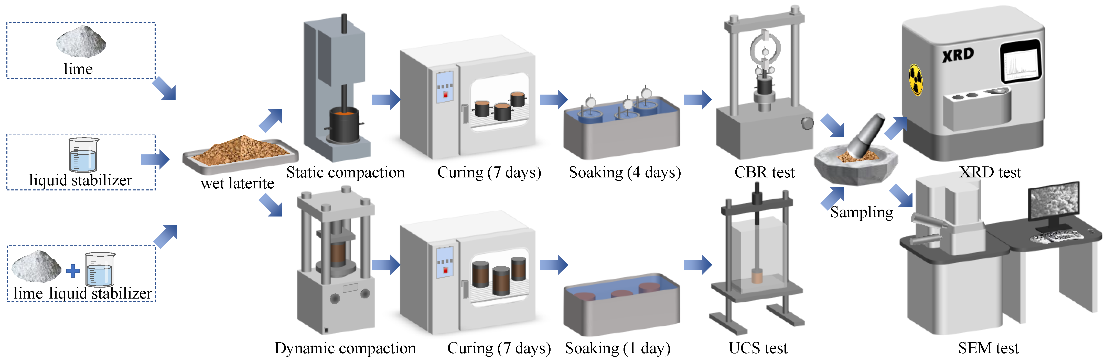
2.4. Flowchart
3. Results
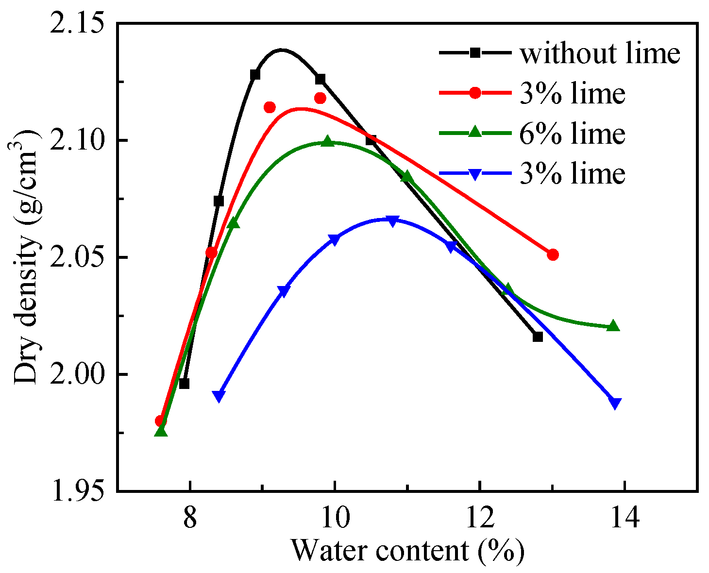
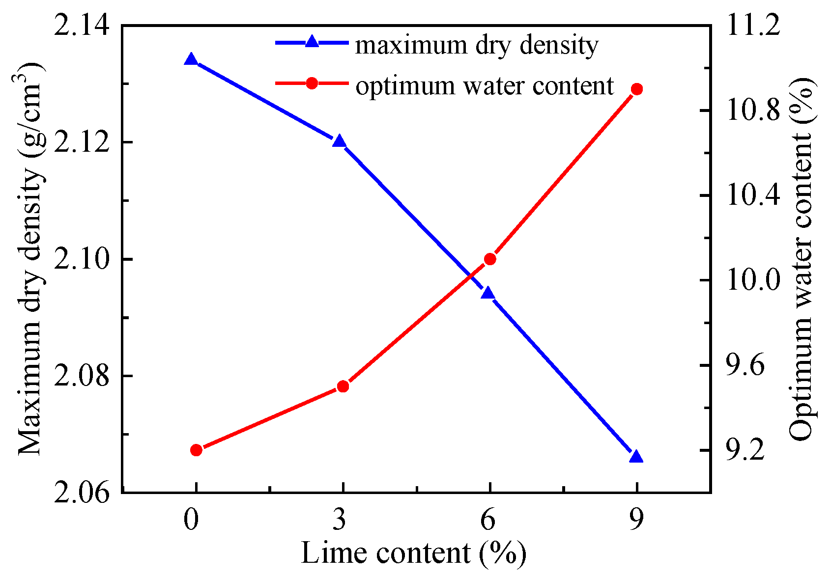
3.1. Maximum Dry Density and Optimal Moisture
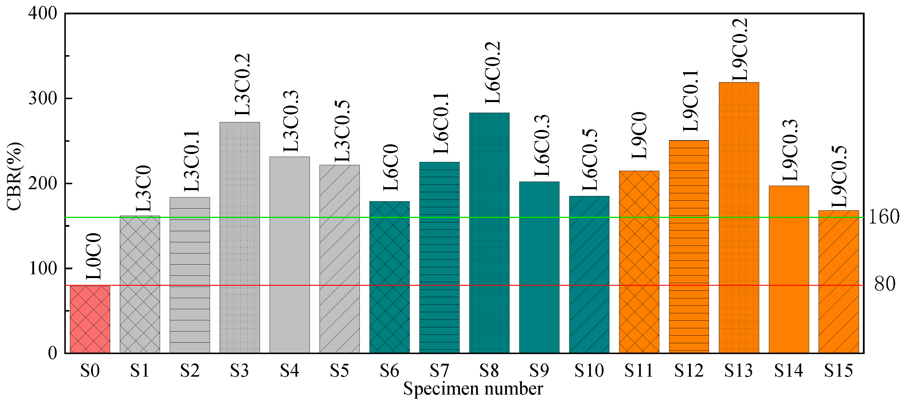
3.2. CBR
3.3. UCS
4. Discussion
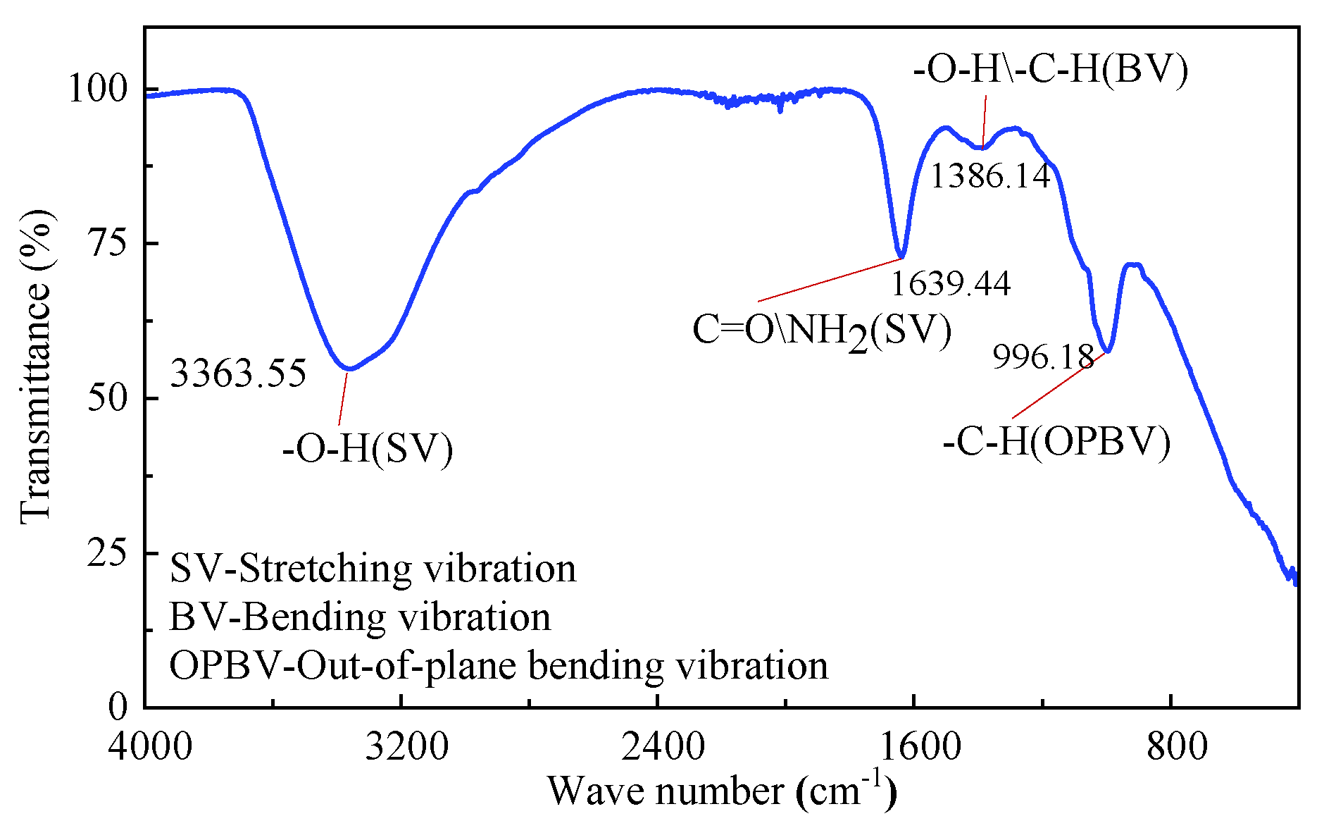
4.1. Mineralogical Characterization
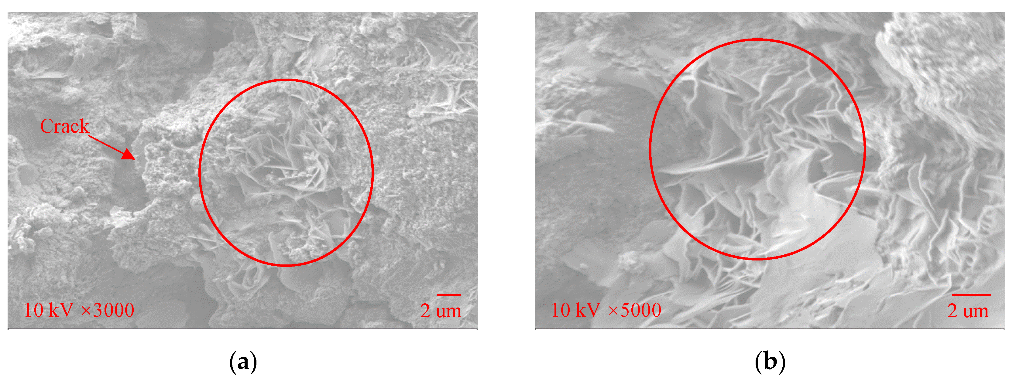
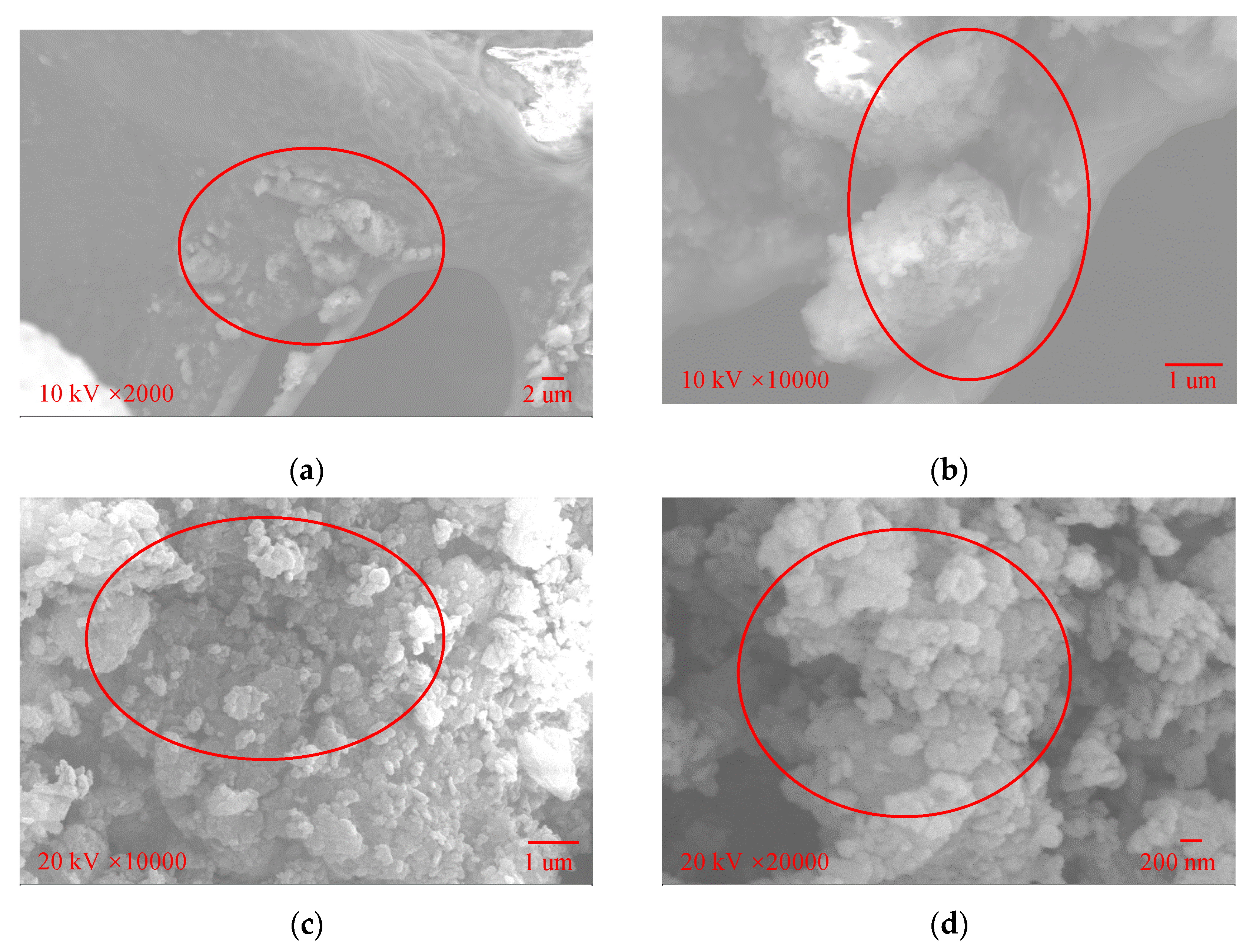
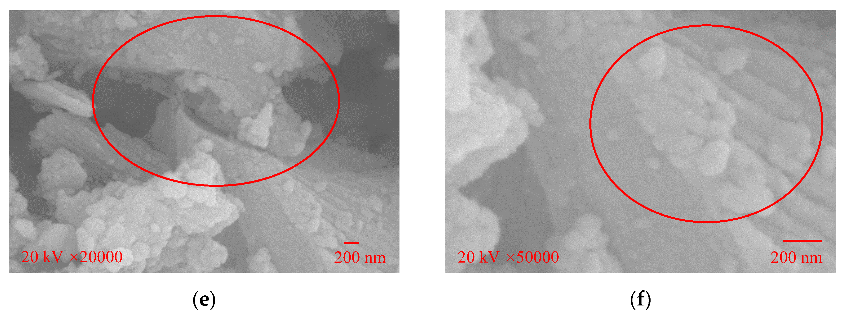
4.2. SEM Image Characterization
4.3. Mechanisms of Hydrated-Lime–Liquid-Stabilizer-Treated Laterite
5. Conclusions
- (1)
- The lime-stabilized laterite exhibited a CBR value of more than 160%, while the lime–liquid-stabilizer-stabilized laterite exhibited a CBR value of more than 250%, indicating that the liquid stabilizer effectively enhances the stabilization effect of lime on natural laterite. The unconfined compressive strength of the lime–liquid-stabilizer-stabilized laterite was at most twice that of the lime-stabilized laterite. The lime–liquid-stabilizer-stabilized laterite can be used at all layers of various subgrades.
- (2)
- Excessive lime and liquid stabilizer may lead to a reduction in CBR and UCS. For the laterite studied in this work, the optimum stabilization effect was achieved with a combination of 6% lime and 0.2 ‰ liquid stabilizer. In practical engineering, it is necessary to determine the optimum dosage of lime and stabilizer.
- (3)
- There is an approximately linear relationship between the CBR value and the UCS value of the stabilized laterite. Additionally, when the UCS value is far lower than that of the lime-stabilized laterite, the corresponding CBR value is almost three times that reported in the literature. These results suggest that the liquid stabilizer greatly improves the water stability of the treated laterite, demonstrating the feasibility of using a curing agent—lime—to stabilize laterite in humid Africa.
- (4)
- Lime hydration results in an exchange between calcium ions and the cations in laterite, increasing the attraction between soil particles. Moreover, hydrated calcium silicate and hydrated calcium aluminate, formed by the further reaction of hydrated lime and laterite, cement soil particles together to form a stable structure. The liquid stabilizer promotes the chemical reaction between lime and soil by reducing the thickness of the double electric layer of soil particles and further improves the strength of the soil by wrapping the mixture of the granular lateritic soil and hydrated lime.
Author Contributions
Funding
Institutional Review Board Statement
Informed Consent Statement
Data Availability Statement
Conflicts of Interest
References
- Gidigasu, M.D. Laterite Soil Engineering: Pedogenesis and Engineering Principles; Elsevier: Amsterdam, The Netherlands, 2012; Volume 9. [Google Scholar]
- Paige-Green, P.; Pinard, M.; Netterberg, F. A review of specifications for lateritic materials for low volume roads. Trans. Geotech. 2015, 5, 86–98. [Google Scholar] [CrossRef]
- Millogo, Y.; Hajjaji, M.; Ouedraogo, R.; Gomina, M. Cement-lateritic gravels mixtures: Microstructure and strength characteristics. Constr. Build. Mater. 2008, 22, 2078–2086. [Google Scholar] [CrossRef]
- Toll, D.G. California Bearing Ratio tests on a lateritic gravel from Kenya. Trans. Geotech. 2015, 5, 59–67. [Google Scholar] [CrossRef]
- Magnan, J.-P.; Ndigye, M. Determination and assessment of deformation moduli of compacted lateritic gravels, using soaked CBR tests. Trans. Geotech. 2015, 5, 50–58. [Google Scholar] [CrossRef]
- Nzabakurikiza, A.; Onana, V.L.; Ze, A.N.; Mvindi, A.T.N.; Ekodeck, G.E. Geological, geotechnical, and mechanical characterization of lateritic gravels from Eastern Cameroon for road construction purposes. Bull. Eng. Geol. Environ. 2017, 76, 1549–1562. [Google Scholar] [CrossRef]
- Ze, A.N.; Onana, V.L.; Mvindi, A.T.N.; Ohandja, H.N.; Eko, R.M.; Ekodeck, G.E. Variability of geotechnical parameters of lateritic gravels overlying contrasted metamorphic rocks in a tropical humid area (Cameroon): Implications for road construction. Bull. Eng. Geol. Environ. 2019, 78, 5531–5549. [Google Scholar]
- Qian, J.S.; Chen, K.W.; Tian, Y.; Zeng, F.; Wang, L. Performance evaluation of flexible pavements with a lateritic gravel base using accelerated pavement testing. Constr. Build. Mater. 2019, 228, 116790. [Google Scholar] [CrossRef]
- Netterberg, F. Review of Specifications for the Use of Laterite in Road Pavements; Crown Agents: Cape Town, South Africa, 2014. [Google Scholar]
- Biswal, D.R.; Sahoo, U.C.; Dash, S.R. Characterization of granular lateritic soils as pavement material. Trans. Geotech. 2016, 6, 108–122. [Google Scholar] [CrossRef]
- Lim, S.M.; Yao, K.; Jiang, Y.; Lim, Z.C.; Bakar, I.H. Geotechnical characteristics of lateritic clay admixed with biomass silica stabilizer. J. Clean. Prod. 2021, 321, 129008. [Google Scholar] [CrossRef]
- Okeke, C.; Abbey, S.; Oti, J.; Eyo, E.; Johnson, A.; Ngambi, S.; Abam, T.; Ujile, M. Appropriate use of lime in the study of the physicochemical behaviour of stabilised lateritic soil under continuous water ingress. Sustainability 2020, 13, 257. [Google Scholar] [CrossRef]
- Saeed, K.A.; Kassim, K.A.; Nur, H.; Yunus, N.Z.M. Strength of lime-cement stabilized tropical lateritic clay contaminated by heavy metals. KSCE J. Civ. Eng. 2015, 19, 887–892. [Google Scholar] [CrossRef] [Green Version]
- Billong, N.; Melo, U.C.; Louvet, F.; Njopwouo, D. Properties of compressed lateritic soil stabilized with a burnt clay–lime binder: Effect of mixture components. Constr. Build. Mater. 2009, 23, 2457–2460. [Google Scholar] [CrossRef]
- Obianyo, I.I.; Onwualu, A.P.; Soboyejo, A.B. Mechanical behaviour of lateritic soil stabilized with bone ash and hydrated lime for sustainable building applications. Case Stud. Constr. Mater. 2020, 12, e00331. [Google Scholar] [CrossRef]
- Osula, D. Lime modification of problem laterite. Eng. Geol. 1991, 30, 141–154. [Google Scholar] [CrossRef]
- Osinubi, K.J. Permeability of lime-treated lateritic soil. J. Transp. Eng. 1998, 124, 465–469. [Google Scholar] [CrossRef]
- Millogo, Y.; Morel, J.C.; Traoré, K.; Ouedraogo, R. Microstructure, geotechnical and mechanical characteristics of quicklime-lateritic gravels mixtures used in road construction. Constr. Build. Mater. 2012, 26, 663–669. [Google Scholar] [CrossRef]
- Eisazadeh, A.; Kassim, K.A.; Nur, H. Solid-state NMR and FTIR studies of lime stabilized montmorillonitic and lateritic clays. Appl. Clay Sci. 2012, 67–68, 5–10. [Google Scholar] [CrossRef]
- Tan, Y.; Hu, M.; Li, D. Effects of agglomerate size on california bearing ratio of lime treated lateritic soils. Int. J. Sustain. Built Environ. 2016, 5, 168–175. [Google Scholar] [CrossRef] [Green Version]
- Ojuri, O.O.; Adavi, A.A.; Oluwatuyi, O.E. Geotechnical and environmental evaluation of lime-cement stabilized soil-mine tailing mixtures for highway construction. Trans. Geotech. 2017, 10, 1–12. [Google Scholar] [CrossRef]
- Amulya, G.; Moghal, A.A.B.; Almajed, A. Sustainable Binary Blending for Low-Volume Roads—Reliability-Based Design Approach and Carbon Footprint Analysis. Materials 2023, 16, 2065. [Google Scholar] [CrossRef]
- Katz, L.E.; Rauch, A.F.; Liljestrand, H.M.; Harmon, J.S.; Shaw, K.S.; Albers, H. Mechanisms of soil stabilization with liquid ionic stabilizer. Transp. Res. Rec. 2001, 1757, 50–57. [Google Scholar] [CrossRef] [Green Version]
- Liu, J.; Shi, B.; Jiang, H.; Huang, H.; Wang, G.; Kamai, T. Research on the stabilization treatment of clay slope topsoil by organic polymer soil stabilizer. Eng. Geol. 2011, 117, 114–120. [Google Scholar] [CrossRef]
- Xiang, W.; Cui, D.; Liu, Q.; Lu, X.; Cao, L. Theory and practice of ionic soil stabilizer reinforcing special clay. J. Earth Sci.-China 2010, 21, 882–887. [Google Scholar] [CrossRef]
- He, S. Chemical Stabilization of Expansive Soils Using Liquid Ionic Soil Stabilizers (LISS); The University of Texas at Arlington: Austin, TX, USA, 2019. [Google Scholar]
- Sarkar, S.L.; Herbert, B.E.; Scharlin, R.J. Injection stabilization of expansive clays using a hydrogen ion exchange chemical. In Advances in Unsaturated Geotechnics; American Society of Civil Engineers: Reston, VA, USA, 2000; pp. 487–516. [Google Scholar]
- Yunus, N.Z.M.; Yung, Y.C.; Wei, N.T.; Abdullah, N.; Mashros, N.; Kadir, M.A.A. Shear strength behaviour of canlite-treated laterite soil. J. Teknol. 2015, 72, 91–97. [Google Scholar]
- Gullu, H.; Hazirbaba, K. Unconfined compressive strength and post-freeze–thaw behavior of fine-grained soils treated with geofiber and synthetic fluid. Cold Reg. Sci. Technol. 2010, 62, 142–150. [Google Scholar] [CrossRef]
- Zhao, H.; Ge, L.; Petry, T.M.; Sun, Y.Z. Effects of chemical stabilizers on an expansive clay. KSCE J. Civ. Eng. 2014, 18, 1009–1017. [Google Scholar] [CrossRef]
- Gautam, S.; Hoyos, L.R.; He, S.; Prabakar, S.; Yu, X. Chemical treatment of a highly expansive clay using a liquid ionic soil stabilizer. Geotech. Geol. Eng. 2020, 38, 4981–4993. [Google Scholar] [CrossRef]
- Wu, X.T.; Sun, J.S.; Qi, Y.; Chen, B. Pore and compression characteristics of clay solidified by ionic soil stabilizer. Bull. Eng. Geol. Environ. 2021, 80, 5003–5019. [Google Scholar] [CrossRef]
- JTG 3430-2020; Test Methods of Soils for Highway Engineering. Ministry of Transport of the People’s Republic of China: Beijing, China, 2020.
- GB 7817-1987; Total Analysis Methods of Forest Soil (GB 7873-87). National Bureau of Standards: Beijing, China, 1987.
- JTG E51-2009; Test Methods of Materials Stabilised with Inorganic Binders for Highway Engineering. Ministry of Transport of the People’s Republic of China: Beijing, China, 2009.
- Wang, Y.; Duc, M.; Cui, Y.J.; Tang, A.M.; Benahmed, N.; Sun, W.J.; Ye, W.M. Aggregate size effect on the development of cementitious compounds in a lime-treated soil during curing. Appl. Clay Sci. 2017, 136, 58–66. [Google Scholar] [CrossRef]
- Osula, D.O. Evaluation of admixture stabilization for problem laterite. J. Transp. Eng. 1989, 115, 674–687. [Google Scholar] [CrossRef]
- Tingle, J.S.; Newman, J.K.; Larson, S.L.; Weiss, C.A.; Rushing, J.F. Stabilization mechanisms of nontraditional additives. Transp. Res. Rec. 2007, 1989, 59–67. [Google Scholar] [CrossRef]
- Vu, H.H.T.; Gu, S.; Thriveni, T.; Khan, M.D.; Tuan, L.Q.; Ahn, J.W. Sustainable treatment for sulfate and lead removal from battery wastewater. Sustainability 2019, 11, 3497. [Google Scholar] [CrossRef] [Green Version]
- Al-Mukhtar, M.; Lasledj, A.; Alcover, J.F. Lime consumption of different clayey soils. App. Clay Sci. 2014, 95, 133–145. [Google Scholar] [CrossRef]
- Vilhena, R.M.; Mascarenha, M.M.D.A.; Angelim, R.R.; Simões, T.D.R.; Oliveira, R.B.D.; Luz, M.P.D. Evaluation of lime-treated lateritic soil for reservoir shoreline stabilization. Water 2020, 12, 3141. [Google Scholar] [CrossRef]
- Johansson, A.; Kollman, P.; Rothenberg, S.; McKelvey, J. Hydrogen bonding ability of the amide group. J. Am. Chem. Soc. 1974, 96, 3794–3800. [Google Scholar] [CrossRef]
- Chemeda, Y.C.; Deneele, D.; Ouvrard, G. Short-term lime solution-kaolinite interfacial chemistry and its effect on long-term pozzolanic activity. Appl. Clay Sci. 2018, 161, 419–426. [Google Scholar] [CrossRef]
- Chavali, R.V.P.; Vindula, S.K.; Babu, A.; Pillai, R.J. Swelling behavior of kaolinitic clays contaminated with alkali solutions: A micro-level study. Appl. Clay Sci. 2017, 135, 575–582. [Google Scholar] [CrossRef]
- Al-Mukhtar, M.; Lasledj, A.; Alcover, J.F. Behaviour and mineralogy changes in lime-treated expansive soil at 20 C. Appl. Clay Sci. 2010, 50, 191–198. [Google Scholar] [CrossRef]
- Federico, A.; Vitone, C.; Murianni, A. On the mechanical behaviour of dredged submarine clayey sediments stabilized with lime or cement. Can. Geotech. J. 2015, 52, 2030–2040. [Google Scholar] [CrossRef]
- Rosone, M.; Celauro, C.; Ferrari, A. Microstructure and shear strength evolution of a lime-treated clay for use in road construction. Int. J. Pavement Eng. 2020, 21, 1147–1158. [Google Scholar] [CrossRef]


| Constituent | Percentage (wt.%) | Constituent | Percentage (wt.%) |
|---|---|---|---|
| SiO2 | 24.650 | Na2O | 0.152 |
| Al2O3 | 19.500 | K2O | 0.094 |
| Fe2O3 | 38.156 | P2O5 | 0.988 |
| CaO | 0.582 | TiO2 | 2.317 |
| MgO | 0.105 | S | 0.039 |
| MnO | 0.027 | Other impurities | 13.390 |
| Properties | Value |
|---|---|
| pH | 11.5 |
| Density (g/cm3) | 1.26 |
| Solid content (%) | 33 |
| NaOH content (%) | 7.0–9.5% |
| Group Number | Hydrated Lime Content /% | Water Content /% | |||||
|---|---|---|---|---|---|---|---|
| 1 | 0 | 8.0 | 8.5 | 9.5 | 10.3 | 11.0 | 13.0 |
| 2 | 3 | 8.0 | 8.5 | 9.5 | 10.3 | 11.0 | 13.0 |
| 3 | 6 | 8.0 | 9.0 | 10.0 | 11.0 | 12.0 | 14.0 |
| 4 | 9 | 8.5 | 9.5 | 10.2 | 11.0 | 12.5 | 14.0 |
| No. | Symbol | Lime Content (wt.%) | ZL-2A Stabilizer Content (wt.‰) | Dry Density (g/cm3) | Water Content (wt.%) |
|---|---|---|---|---|---|
| S0 | L0C0 | 0 | 0 | 2.134 | 9.1 |
| S1 | L3C0 | 3 | 0 | 2.120 | 9.5 |
| S2 | L3C0.1 | 3 | 0.1 | 2.120 | 9.5 |
| S3 | L3C0.2 | 3 | 0.2 | 2.120 | 9.5 |
| S4 | L3C0.3 | 3 | 0.3 | 2.120 | 9.5 |
| S5 | L3C0.5 | 3 | 0.5 | 2.094 | 10.1 |
| S6 | L6C0 | 6 | 0 | 2.094 | 10.1 |
| S7 | L6C0.1 | 6 | 0.1 | 2.094 | 10.1 |
| S8 | L6C0.2 | 6 | 0.2 | 2.094 | 10.1 |
| S9 | L6C0.3 | 6 | 0.3 | 2.094 | 10.1 |
| S10 | L6C0.5 | 6 | 0.5 | 2.094 | 10.1 |
| S11 | L9C0 | 9 | 0 | 2.066 | 10.9 |
| S12 | L9C0.1 | 9 | 0.1 | 2.066 | 10.9 |
| S13 | L9C0.2 | 9 | 0.2 | 2.066 | 10.9 |
| S14 | L9C0.3 | 9 | 0.3 | 2.066 | 10.9 |
| S15 | L9C0.5 | 9 | 0.5 | 2.066 | 10.9 |
Disclaimer/Publisher’s Note: The statements, opinions and data contained in all publications are solely those of the individual author(s) and contributor(s) and not of MDPI and/or the editor(s). MDPI and/or the editor(s) disclaim responsibility for any injury to people or property resulting from any ideas, methods, instructions or products referred to in the content. |
© 2023 by the authors. Licensee MDPI, Basel, Switzerland. This article is an open access article distributed under the terms and conditions of the Creative Commons Attribution (CC BY) license (https://creativecommons.org/licenses/by/4.0/).
Share and Cite
Tang, K.; Zeng, F.; Shi, L.; Zhu, L.; Chen, Z.; Zhang, F. Mechanical Behavior of Hydrated-Lime–Liquid-Stabilizer-Treated Granular Lateritic Soils. Sustainability 2023, 15, 5601. https://doi.org/10.3390/su15065601
Tang K, Zeng F, Shi L, Zhu L, Chen Z, Zhang F. Mechanical Behavior of Hydrated-Lime–Liquid-Stabilizer-Treated Granular Lateritic Soils. Sustainability. 2023; 15(6):5601. https://doi.org/10.3390/su15065601
Chicago/Turabian StyleTang, Kangwei, Feng Zeng, Liang Shi, Long Zhu, Zining Chen, and Feng Zhang. 2023. "Mechanical Behavior of Hydrated-Lime–Liquid-Stabilizer-Treated Granular Lateritic Soils" Sustainability 15, no. 6: 5601. https://doi.org/10.3390/su15065601