
Thermal Performance and Optimizing of Composite Trombe Wall with Temperature-Controlled DC Fan in Winter


1
Innovation Institute for Sustainable Maritime Architecture Research and Technology, Qingdao University of Technology, Qingdao 266033, China
2
Faculty of Environmental Engineering, The University of Kitakyushu, Kitakyushu 808-0135, Japan
*
Author to whom correspondence should be addressed.
Sustainability 2022, 14(5), 3080; https://doi.org/10.3390/su14053080
Submission received: 5 February 2022
/
Revised: 22 February 2022
/
Accepted: 23 February 2022
/
Published: 7 March 2022
(This article belongs to the Topic Sustainable Built Environment)
Abstract
:This paper discusses an improved approach to the Trombe wall: an insulated panel is installed on the inner side, and vents are installed at the top and bottom to connect the outer and inner air layer with the interior. Direct current (DC) fans are installed in the upper vents for stable control of the air circulation. The study first analyzed the thermal performance of this composite Trombe wall, for which the heat load was 27.3% less compared to the classic Trombe wall and 32.1% less compared to the case without the Trombe wall. However, its efficiency for heating the room temperature was not high without heating. Then, we optimized the ventilation efficiency, the proportion of the Trombe wall in the room, and the type of glazing. The highest heat load savings could be achieved when the ventilation openings used high ventilation with temperature-controlled fans and the Trombe wall about 3% of the house floor area. With the use of Low-e double-glazing, we were able to save nearly 41.3% of the heat load than that with the regular single-glazing. For the composite Trombe wall, after taking into account the optimization factors, the room temperature was significantly higher, and could save nearly 52.3% of energy compared to the pre-optimization period.
1. Introduction
The building industry has the highest energy consumption in the world, most of which is used for heating, ventilation, and air conditioning systems (HVAC) [1,2]. The energy consumption of buildings for cooling and heating accounts for 18–73% of their total energy consumption. Heating energy consumption accounts for 32–33% of the total building energy consumption [3]. Japanese buildings use more than 30% of their energy consumption for heating [4]. In order to achieve thermal comfort inside the building, the use of solar energy design to save energy in the building has attracted more and more attention [5]. Solar energy technology can reduce the annual heating demand by 25% [6]. The best building design strategy can save 63% to 76% of energy [7].
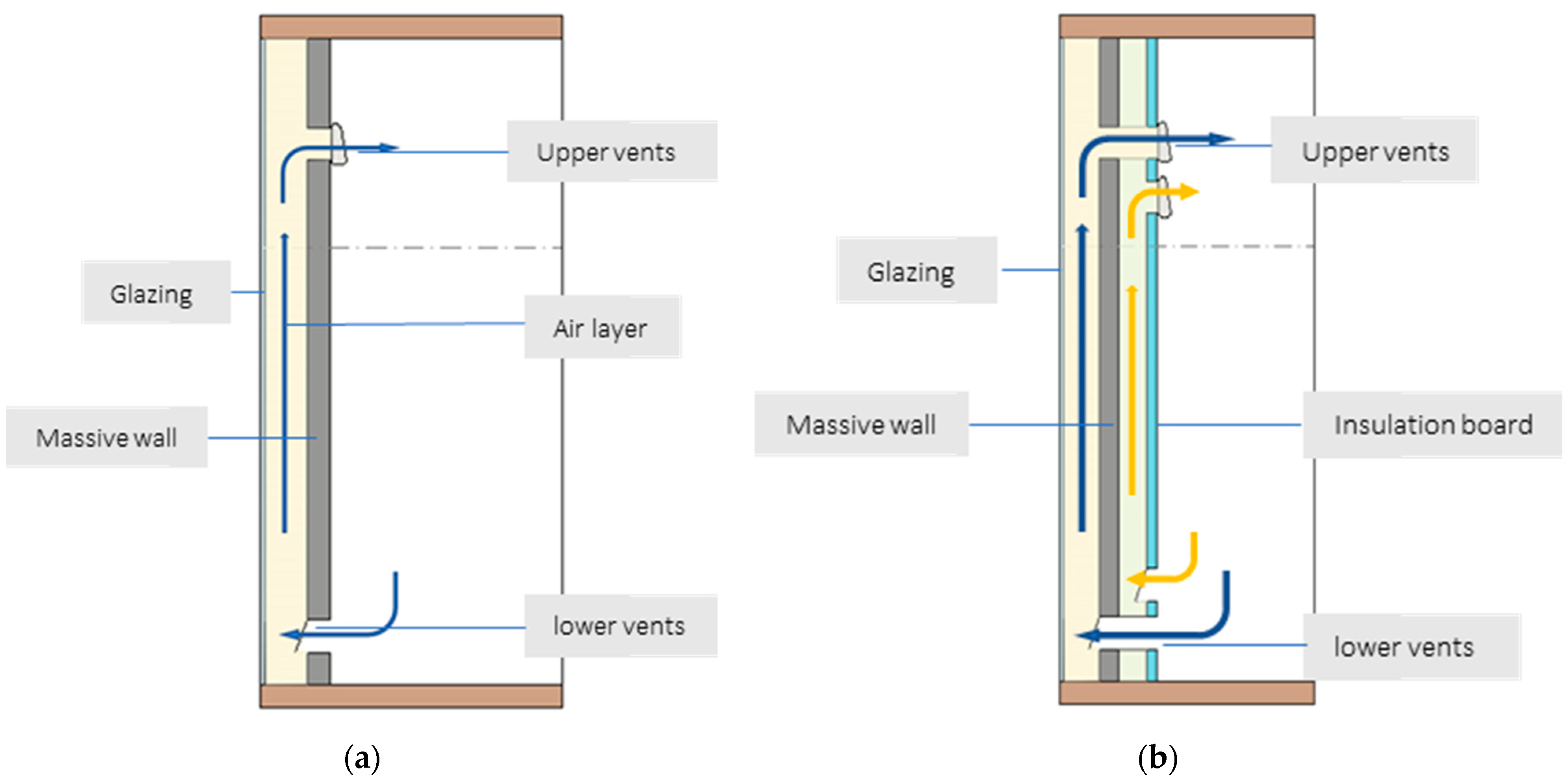
Since 1881, when Edward Morse first proposed the idea of using solar energy in architecture [2,8], the discussion has not stopped. In 1940, Fred Keck painted the walls black, making it possible to convert solar radiation into heat and to accumulate it into heat rooms at night [9]. In 1967, Felix Trombe and Jacques Michel designed and patented a low-rise apartment building that is known as the classic Trombe wall [10]. The Trombe wall is a south-oriented energy storage wall with an air layer and glazing surface [1,2,3]. The Trombe wall’s operational principle is that solar radiation heats a massive wall. A massive wall heats the air in the room by radiation and convective heat exchange. Air vents located in the upper and lower parts of the massive wall are used to ensure the necessary air circulation [2,11].
To increase the thermal resistance and control the supply of Trombe walls, composite Trombe−Michel walls were developed [12]. This type of Trombe wall consists of glazing, an air gap, a massive wall without ventilation ducts, an air layer, and an insulated wall with ventilation ducts.
The thickness of the massive wall is often considered in studies. Briga-Sá et al. [13] used a calculation methodology for the Trombe wall based on International Organization for Standardization (ISO) 13790:2008 (E), and studied its behavior at 15 cm, 20 cm, 25 cm, 30 cm, 35 cm, and 40 cm thicknesses. The obtained results show that in the heating season, if the Trombe wall is ventilated, the heat gain increases with the increase in the thickness of a massive wall. However, in the case of unventilated Trombe walls, the heat gain decreases when the thickness increases. The thicker the wall, the longer it takes for the heat to reach the interior. In this direction, Agrawal and Tiwari propose the optimal thickness of concrete Trombe walls to be 30–40 cm [2,14].
Basak K. et al. [15,16] compared the energy performance of single-glazed, double-glazed, and a-Si translucent photovoltaic (PV) modules on a Trombe wall. It was found that the double glazing had a higher thermal insulation performance at night and in the evening. A higher thermal insulation performance was found in the evening. The temperature in the air ducts in the PV module section was lower than in the double and single glazed sections due to the lower solar radiation transmission in the PV module section. Another set of experiments was conducted by Irshad K. et al. [11,16] in Malaysia, examining different photovoltaic glazing types (i.e., PV single glazing, PV double glazing, and PV double glazing filled with gas (Argon)). Zhou L. et al. [17] proposed a composite Trombe wall that combines the water wall with the traditional Trombe wall. The results show that water Trombe wall that replaced the glass surface with water could reduce the heat loss by 31% compared to the Trombe wall. Azhar A. et al. [18] undertook a practical investigation about effect of a glass cover on the efficiency of the photovoltaic/Trombe wall. The highest recorded thermal efficiency value was 80% using a glass cover and 0.5% nanofluid. Arash P. et al. [19] investigated the effect of different structural and spectral glass specifications. The physical properties had the greatest impact on increasing comfort periods (up to 32%) and reducing cooling periods (up to 35%). Licholai L. [20] researched the influence of the glazing parameters with different heat transfer coefficients and total solar energy transmittance factors on the thermal performance of the Trombe wall containing a phase change material (PCM).
Li D. et al. [21] studied the pattern of the air flow rate in the Trombe wall, and when the wall height increased, the ascending rate of air velocity increased. A combined solar chimney was proposed by Liu H. et al. that integrated an inclined-roof solar chimney with a traditional Trombe wall [22]. Briga-Sá et al. [23] suggested that during the heating season, air vents should be open when solar radiation values exceed 100 W/m2.
Ji J. et al. [24] applied direct current (DC) fans to the PV/Trombe wall (PV-TW) for simulation and practical testing. It was found that the room temperature was significantly increased and the PV cells were cooled to some extent by applying the DC fan. The potential of PV-TW can be exerted by the assisted DC fan. Ma Q. [25] investigated energy conservation in a concrete construction office building with a composite Trombe wall with a temperature-controlled DC fan for application in winter heating. The ventilation rates of the fan were controlled at 40 m3/h. It was more efficient to have the fan start up when the ventilated air cavity temperature was 19 °C if the operative temperature of the interior was maintained at 20 °C with air conditioning. In [26], the effects of fans that were turned on and off at different times were also investigated. It was found to be the best to supply air from the inner-ventilated air layer in December, February, and March. It was found to be best to supply air from the outer-ventilated air layer and inner-ventilated air layer together in November. In January, it was found to be better to not supply air.
This study aims to discuss a composite double-layer Trombe wall with a temperature-controlled DC fan. So far, there is no overall study on the influencing factors such as the fan rate. The main object of this Trombe wall that transmits heat to the room is transformed from the massive wall into the vents, and the efficiency of the heat transfer will be reduced while reducing the heat dissipation. The research aimed to understand whether the overall benefit it brings is positive, as well as the overall thermal performance of this new Trombe wall in hot summer and cold winter regions. In addition, the dynamic heat load calculation software THERB for HAM [27], developed by Akihito Ozaki, used in this study, needs to be understood in terms of its applicability to this particular air circulation in the Trombe wall. For these purposes, a house with wood bars as the main structural material was constructed in Kitakyushu, Fukuoka Prefecture (33.88, 130.70), Japan, in 2018, as a basic research object, and it was used as a reference to build numerical models. We combined real measurements and simulations to calculate the overall thermal performance of the composite double-layer Trombe wall and to optimize it in terms of massive wall thickness, fan rate, glazing type, etc., so as to provide a better reference for future practical validation and utilization.
2. Materials and Methods
2.1. House Description
2.1.1. Reference House
The reference house was a small building built for the experiments. The overall width of the reference house was 2.70 m and the depth was 2.785 m. The roof was sloping and the total height was 3.98 m (including foundation). The main structure material was Japanese fir (length 3000 mm, width 105 mm, and height 105 mm), with a 30 mm insulation layer inside and a galvalume steel plate as the outer enclosure structure. The interior floors, ceilings, and walls of the reference house were lined with insulation panels with a thermal conductivity of 0.036 W/mK. The structure of each part is shown in Table 1.
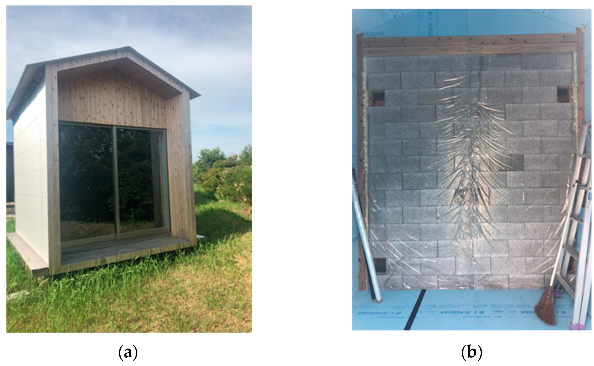
The entire south elevation of the house was designed in a classic Trombe wall configuration; the massive wall was constructed of 100 mm thick concrete blocks with a total dimension of 2.63 m × 2. 34 m. The outside of the concrete massive wall was covered with a layer of dark film, so as to improve the absorptivity of the massive wall. The glass layer of the Trombe wall was a single floor-to-ceiling glass window that could be opened. Figure 1 shows the south elevation of the reference house with the entire glazing surface belonging to the Trombe wall. The structure of each part is shown in Table 2.
The reference house is not equipped with light-permeable windows, and Figure 1 shows the south elevation and interior of the house.
2.1.2. Numerical Model for Validation and Optimized Model
The structure of the numerical model for validation was the same as the reference room.
There were still some disadvantages, such as a low thermal resistance and inverse thermo-siphon phenomena, which occur when the massive wall has a lower temperature than room temperature, particularly during the night in the cold season, when reversing the air circulation through the vents chills the room even more [1] than the classic Trombe wall.
Following these shortages, a composite double-layer Trombe wall, which had an added interior wall made of insulating material (Styrofoam board), was constructed inside the classic wall. It had two ventilated air vents (between the wall and the glass, and between the wall and insulation) as shown in Figure 2. The use of a DC fan on the upper vents would control the thermal cycling of the indoor air and the air layer automatically according to the temperature of the ventilated air vents.
2.2. Software–THERB for Ham
This study uses THERB for Ham software using a calculation code written in Fortran language, originally developed by Akihito Ozaki, which combines the simulation of heat and moisture transfer with air flow to explore effective methods of utilizing the internal heat of solar spaces [27]. This software has complete HAM (heat, air, and moisture) features such as conduction, convection, radiation, and ventilation (or air leakage), including principles of moisture transfer within walls [29,30]. Depending on the building input model, rooms (spaces) can be arbitrarily divided into living rooms (including under-floor, inter-floor spaces, and stairwells) or air layers. The simulation has been validated through standardized tests in Japan, such as the Balance Evaluation Systems Test (BESTest) procedure [30], and is approved by the Japanese government as an evaluation method for annual heating and cooling load calculation methods according to the law concerning the promotion of housing quality assurance.
2.3. Location, Weather, and Measurement Instruments
The reference house for the measurements was located in Kitakyushu, Japan (33.88, 130.70). The climate of Kitakyushu is temperate humid, with quite cold winters and hot, moist, and rainy summers. According to the Japan Meteorological Agency (JMA), Kitakyushu is located in the northern part of Kyushu. In winter, prevailing northwesterly winds cause the advection of cold air from Siberia to Kyushu (North) and bring cloudy conditions to the area, although the amount of precipitation is small.
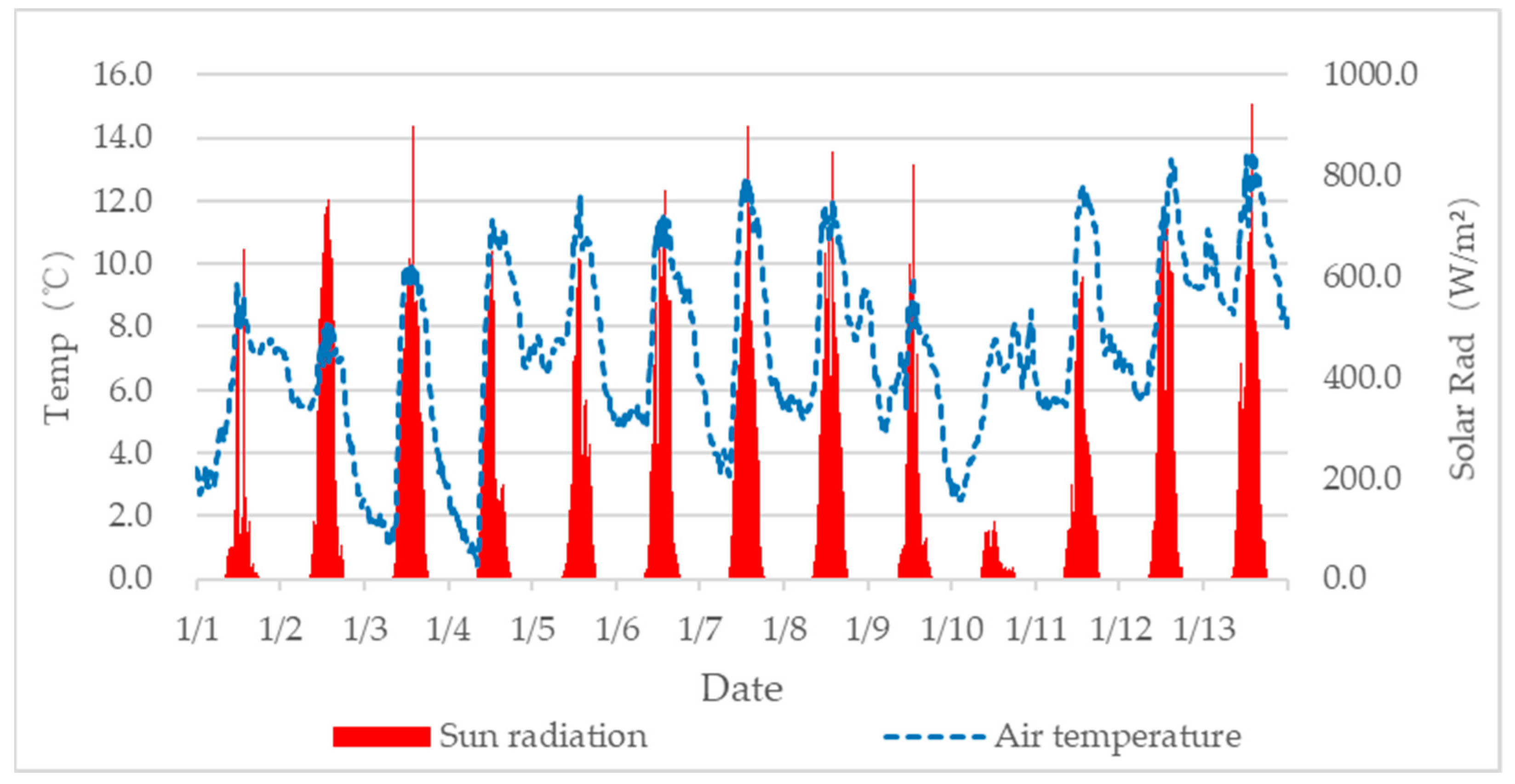
A weather station was set up at the neighboring location of the reference house during the actual measurement and verification phase, and simultaneously tested the local weather conditions (air temperature, humidity, solar radiation, wind direction and speed, etc.) as well as the indoor temperature of the reference house every 10 min from 1 January to 13 January 2020. The outside temperature and solar radiation situation is shown in Figure 3.
The meteorological data (air temperature, humidity, solar radiation, wind direction and speed, etc.) used for the year-round simulations used the meteorological standard year’s data of the Automated Meteorological Data Acquisition System (AMeDAS) collected locally in Yahata Kitakyushu (33.51, 130.44).
3. Results
3.1. Result of Measurement
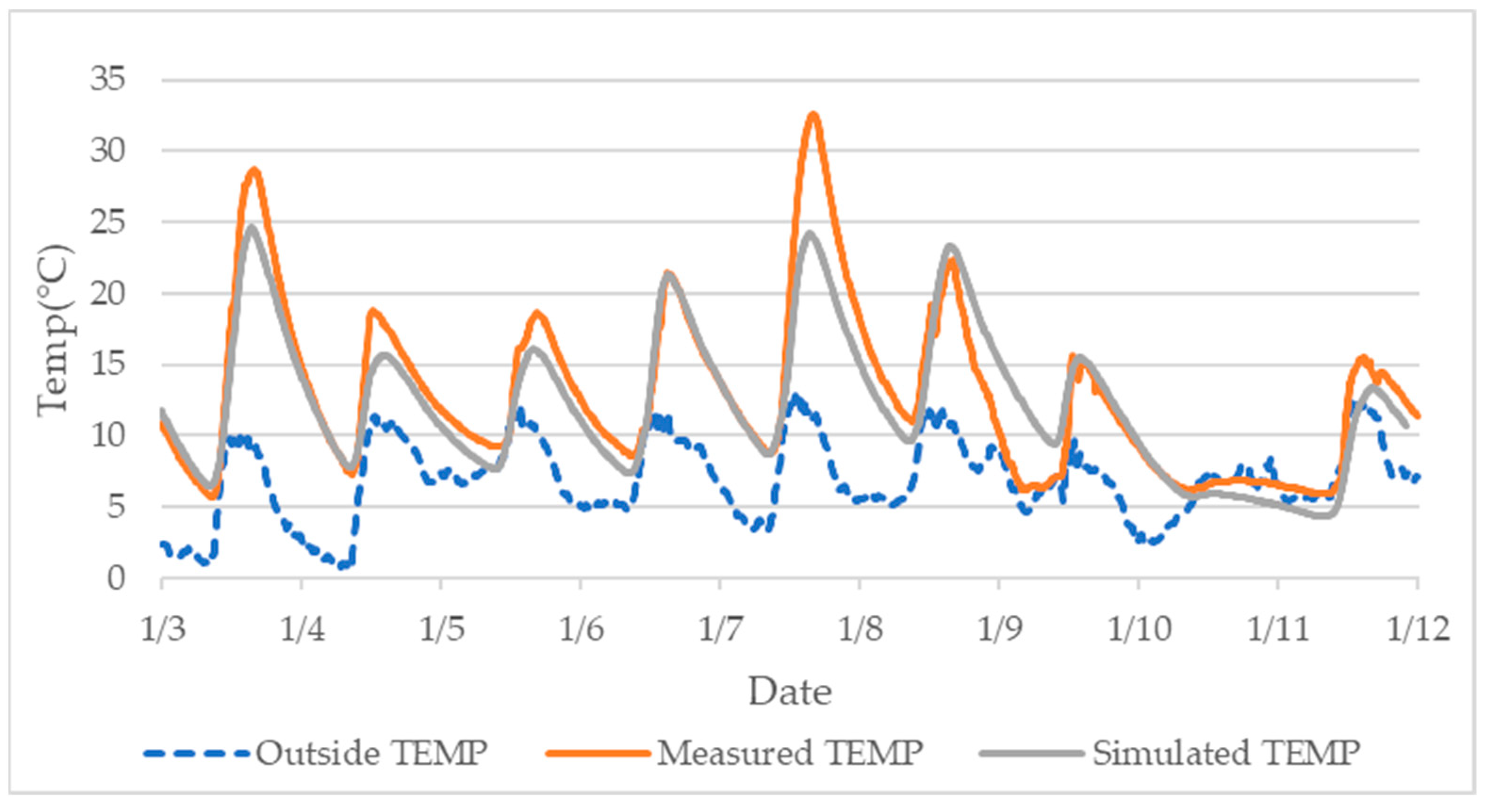
Figure 4 shows the comparison of the indoor temperature between the measured data and the simulated calculated data by THERB for Ham Software (every 10 min) from 3 January to 12 January.
It was found that on some days, especially around 7 January, there was a slight discrepancy between the measured data and the simulated calculated data. An analysis of the possible causes was performed. The DC fan that controlled the wind speed was not placed in the experimental cabin, and the internal air circulation was caused by the temperature difference between the air layer and the room, and the flowing air volume was different at each moment. The software’s ventilation was calculated at hourly intervals, which could produce errors in the case of wind speed changes, especially when the actual temperature changes were very drastic. This large error can be avoided if the case of using DC fans is simulated, i.e., if the ventilation rate per hour is constant.
In conclusion, the overall trend of the data was consistent and the simulated temperatures largely matched the actual temperatures, which confirms the applicability of the simulation software. So, we continued to use the data from the experimental log cabin and THERB for HAM software for the next simulation.
3.2. Thermal Performance of Composite Trombe Wall
This study compared the classical Trombe wall and the modified composite Trombe wall with a normal house without a Trombe wall (with the same envelope on the south façade as the other façades).
The air conditioning heating season was from 1 November to 31 March (in meteorological standard year), and the setting temperature was unified to 20 °C. In addition, it simulated the residential mode, and the air-conditioning operation time was from 18:00 p.m. to 09:00 a.m. According to the review of [25], with forced ventilation of 40 m3/h by DC between the air layer and indoor space in the Trombe wall, the ventilation temperature was controlled to 19 °C, that is, when the temperature of the sensing part was higher than 19 °C, the DC fan was operated, and hot air was sent into the room and the lower air hole was opened by default to send cold air into the air layer to create air circulation.
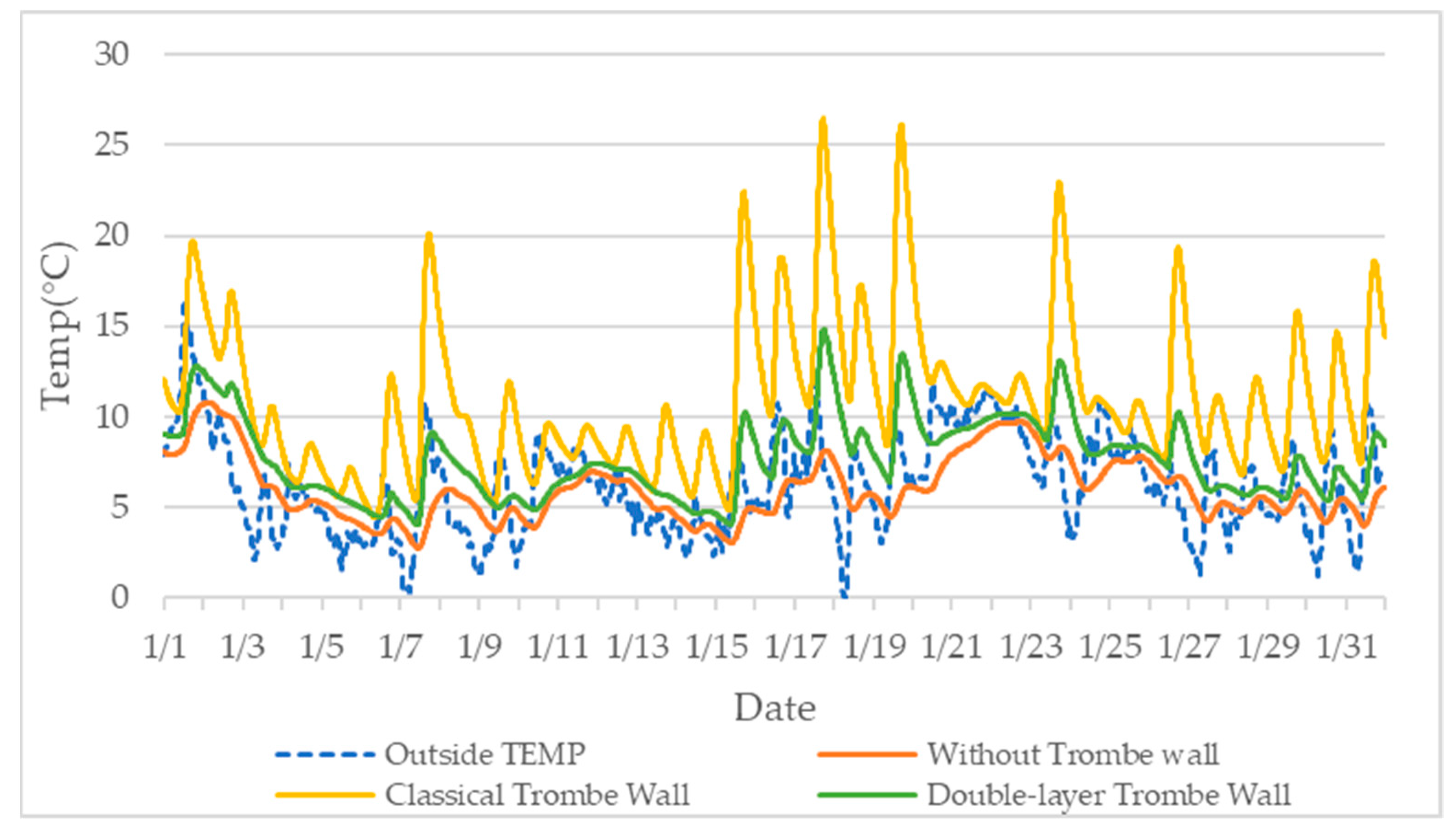
By comparing the indoor temperatures in January, the coldest month of the year without air conditioning, as seen in Figure 5, we found that the thermal performance of the improved wall was not as good as was expected. Although the indoor temperature was higher than the indoor temperature without the Trombe wall, because of the lack of thermal radiation effect of the massive wall, the maximum indoor temperature in January could only reach about 15 °C without using an air conditioner. Its thermal performance was not as good as that of the classic Trombe wall.
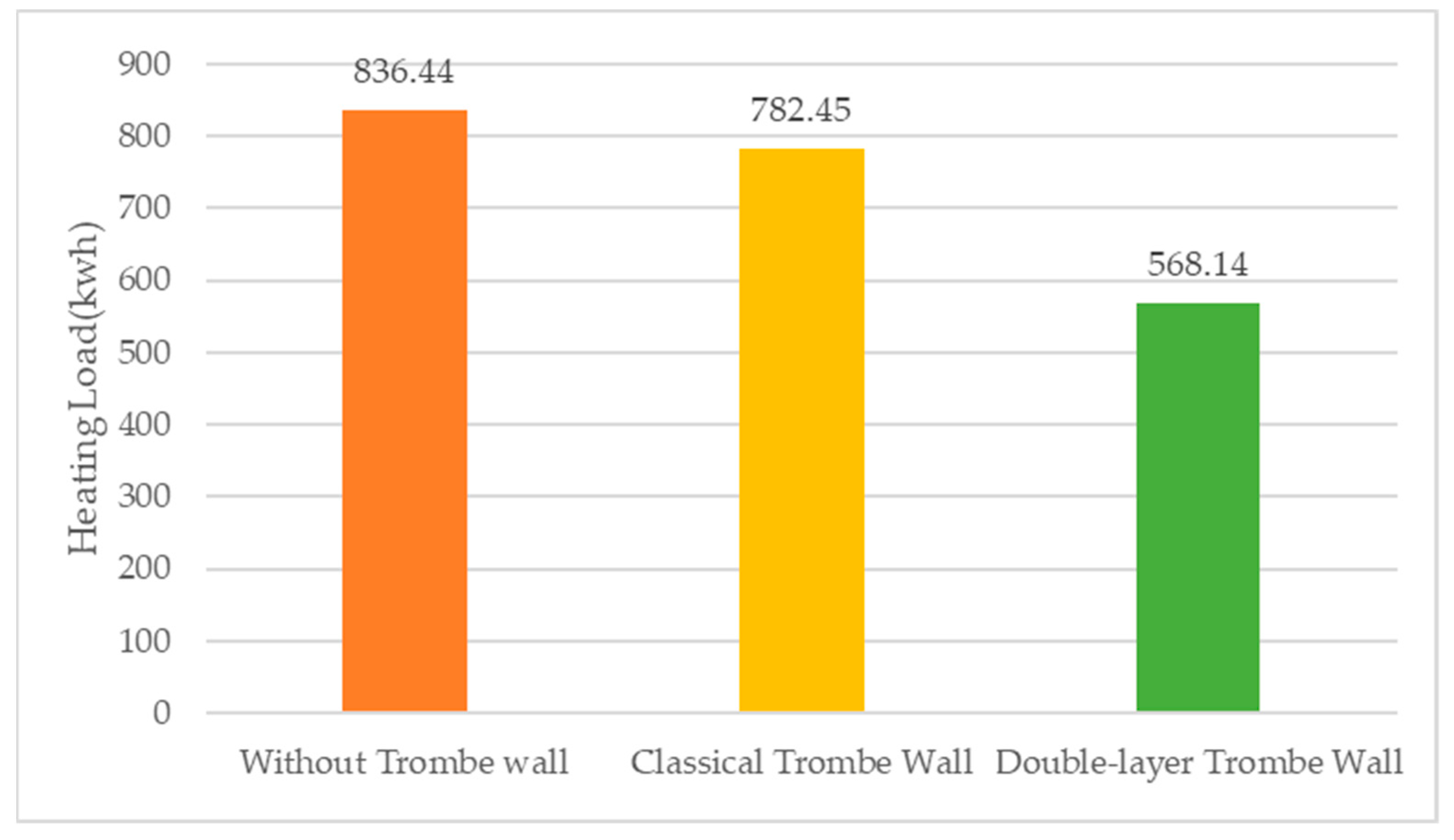
However, in Figure 6, the annual winter heat load calculated after using air conditioning is compared. It was found that the annual heat load of the improved composite double-layer Trombe wall was 568.14 kWh, which was 27.3% less compared to the classic Trombe wall and 32.1% less compared to the case without the Trombe wall. Therefore, the improved composite has potential that needs to be studied.
3.3. Optimization of Composite Trombe Wall
The heat loss of window glass is a major part of a building’s energy consumption, accounting for more than 50% of the building’s energy consumption. Here, we explored the effects of different types of glazing on thermal energy consumption.
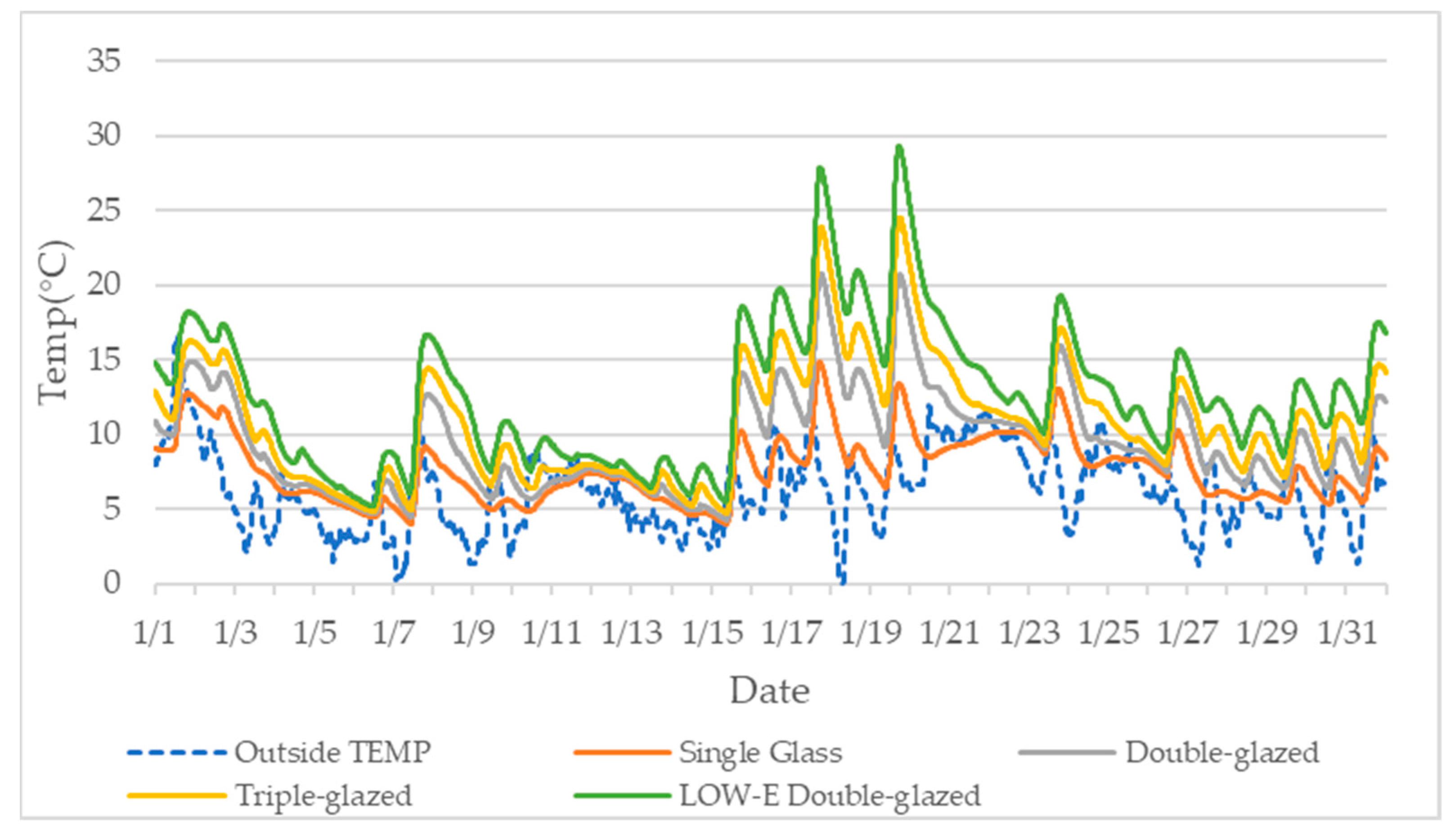
By comparing the effects of different types of glazing on the change of room temperature in the state without air conditioning, the results of the room temperature are showed in Figure 7, indicating that the best heat collecting and heat insulating performance was double-glazed with a low emissivity (low-E) layer (low-E layer plated on the inner glazing) in the absence of air conditioning. Compared to single-layer glass, multi-layer glass can significantly improve heat collection and thermal insulation properties. In addition, the triple-glazing window was more effective with more air layers.
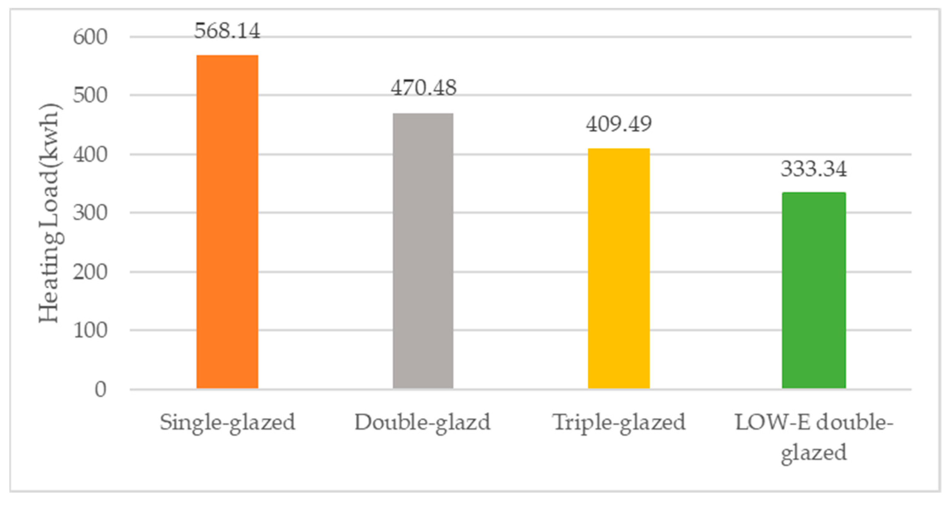
For the comparison of energy consumption during heating, as seen in Figure 8, multi-layer glass was better than single-layer glass regarding the thermal insulation performance, and the more layers, the better the thermal insulation performance. In addition, the use of low-E glass greatly reduced the indoor heat transfer to the outdoor caused by radiation, thus achieving the desired energy saving effect. During the whole heating season, compared with the single layer glass window, the energy ratios that were saved using the double-glazed window, triple-glazed window, and low-E double-glazed window were 17.19%, 27.89%, and 41.33%, respectively.
Massive wall materials and thickness contribute importantly to the efficiency of the wall’s heat storage and release capacity. Massive wall thickness has been experimented several times in the Trombe wall study. According to some conclusions, construction of a classical Trombe wall with 3.20% of the building floor area can get the best result [12]. The study needs to understand the effect of this parameter on the new composite double-layer Trombe wall.
The massive wall in the reference house was built with concrete blocks of 100 mm thickness. For possible further validation in the future and considering the ratio of the massive wall to the house area, the simulation used 50 mm, 100 mm, 150 mm, and 200 mm thicknesses, corresponding to about 1.7%, 3.0%, 5.0%, and 6.7%, respectively, of the building floor area.
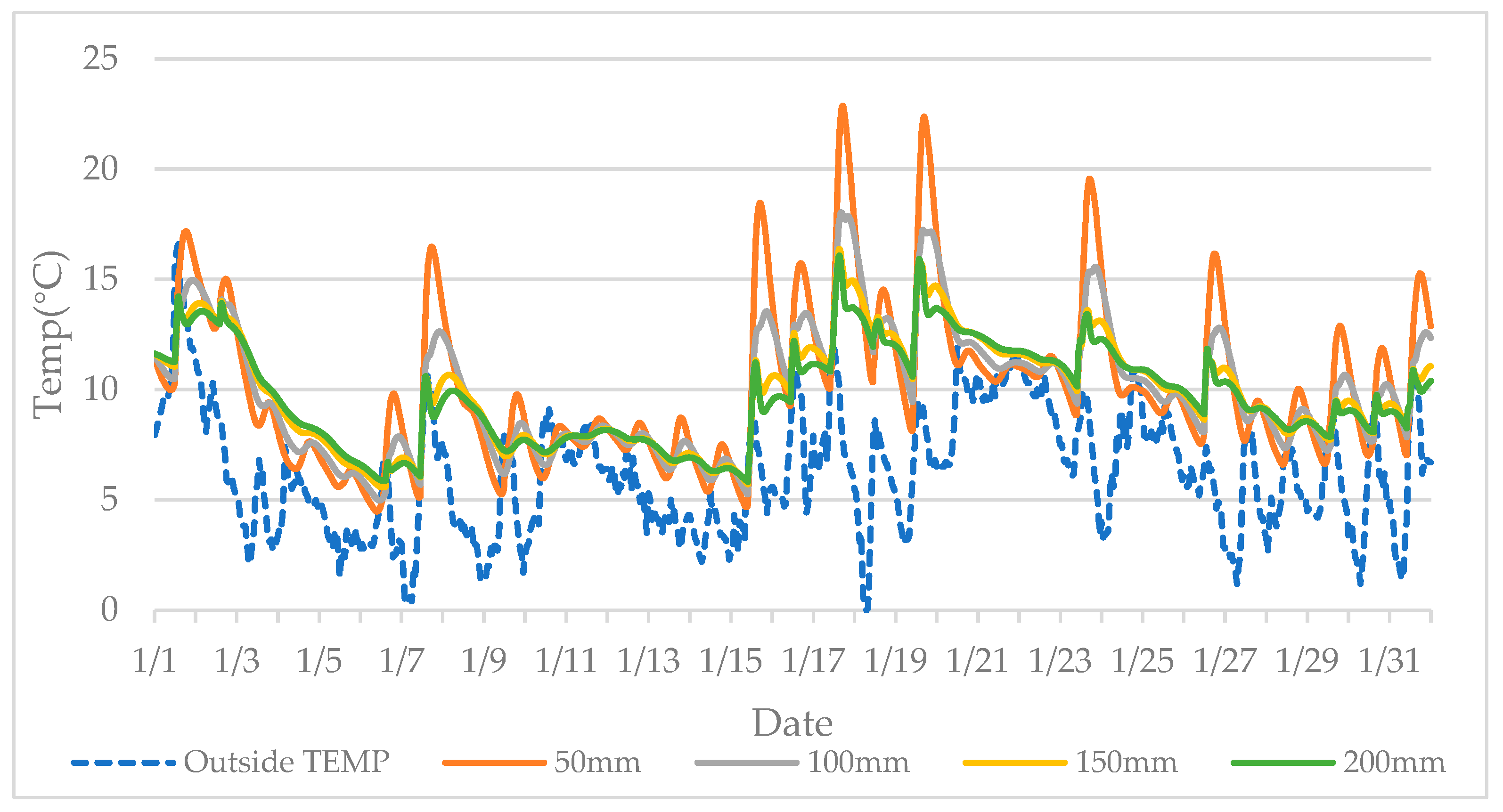
When comparing the indoor temperature without air conditioning (as in Figure 9), it was found that the smaller the thickness of the massive wall, the higher the maximum indoor temperature that could be achieved. However, at the same time, the minimum temperature at night was significantly lower than that of the thicker massive wall, and the temperature fluctuated more.
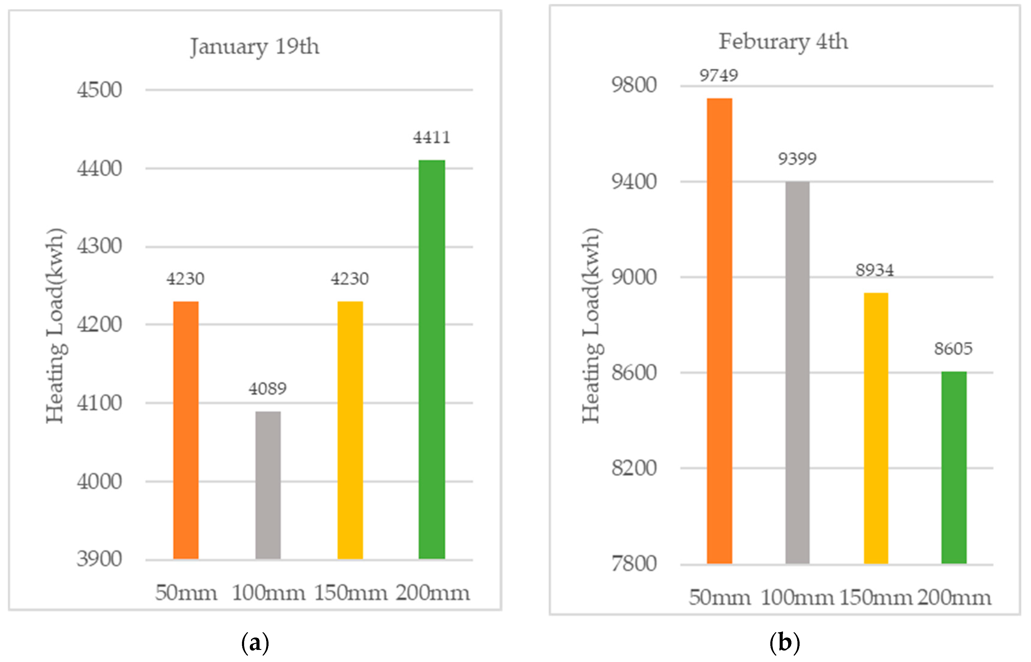
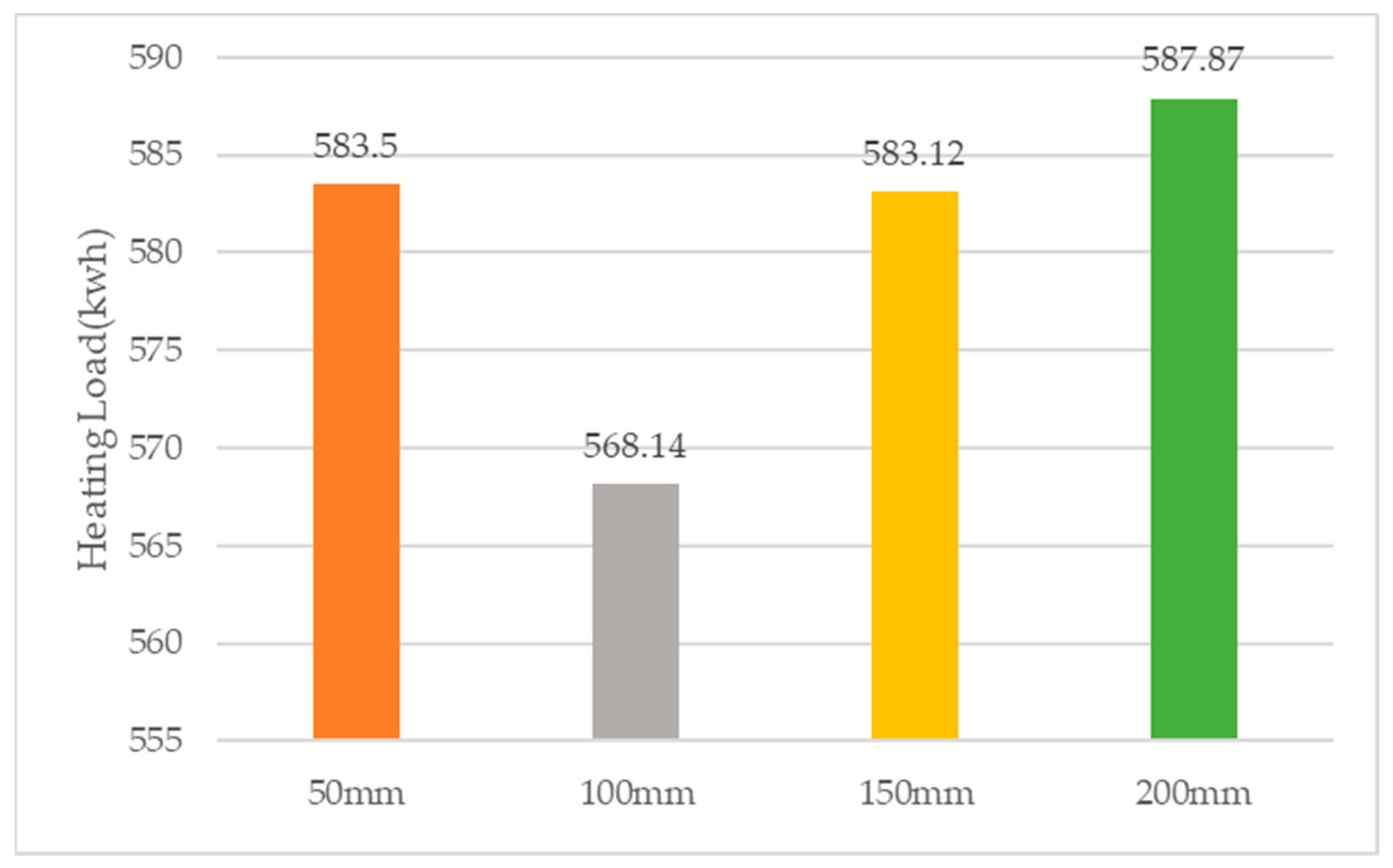
Considering the results of the comparison of specific heat loads, the walls of thin thicknesses lost heat quickly due to the rapid drop in temperature at night. However, this was not the case for the thicker walls, which showed a better effect. Data were extracted for a sunny day (19 January) and a cloudy day (4 February) for comparison in Figure 10, and the graph shows that on the sunny day, the 100 mm thick massive wall had the lowest heat load, while on the cold, cloudy day, the thicker the massive wall, the more air conditioning load it saved. As shown in Figure 11, the annual thermal energy consumption of a 100 mm thick massive wall (3.0% of the building floor area) was the lowest in winter climate conditions in Kitakyushu, Japan.
The DC fan set in the upper vents controlled the rate of inner air circulation and outer air circulation, i.e., the rate of hot air transfer, for which no specific values have been calculated in previous studies of composite Trombe walls.
The ventilation volume of the DC fan the experiment was chosen as a reference, with an adjustment range of 0 m3/h to 70 m3/h. Setting the fans at the two upper side vents, the limit case could obtain a ventilation volume of 140 m3/h. So, the numerical experiments simulated the air supply at 20 m3/h, 40 m3/h, 70 m3/h, 110 m3/h, and 140 m3/h, respectively, and were conducted with no forced ventilation as the control.
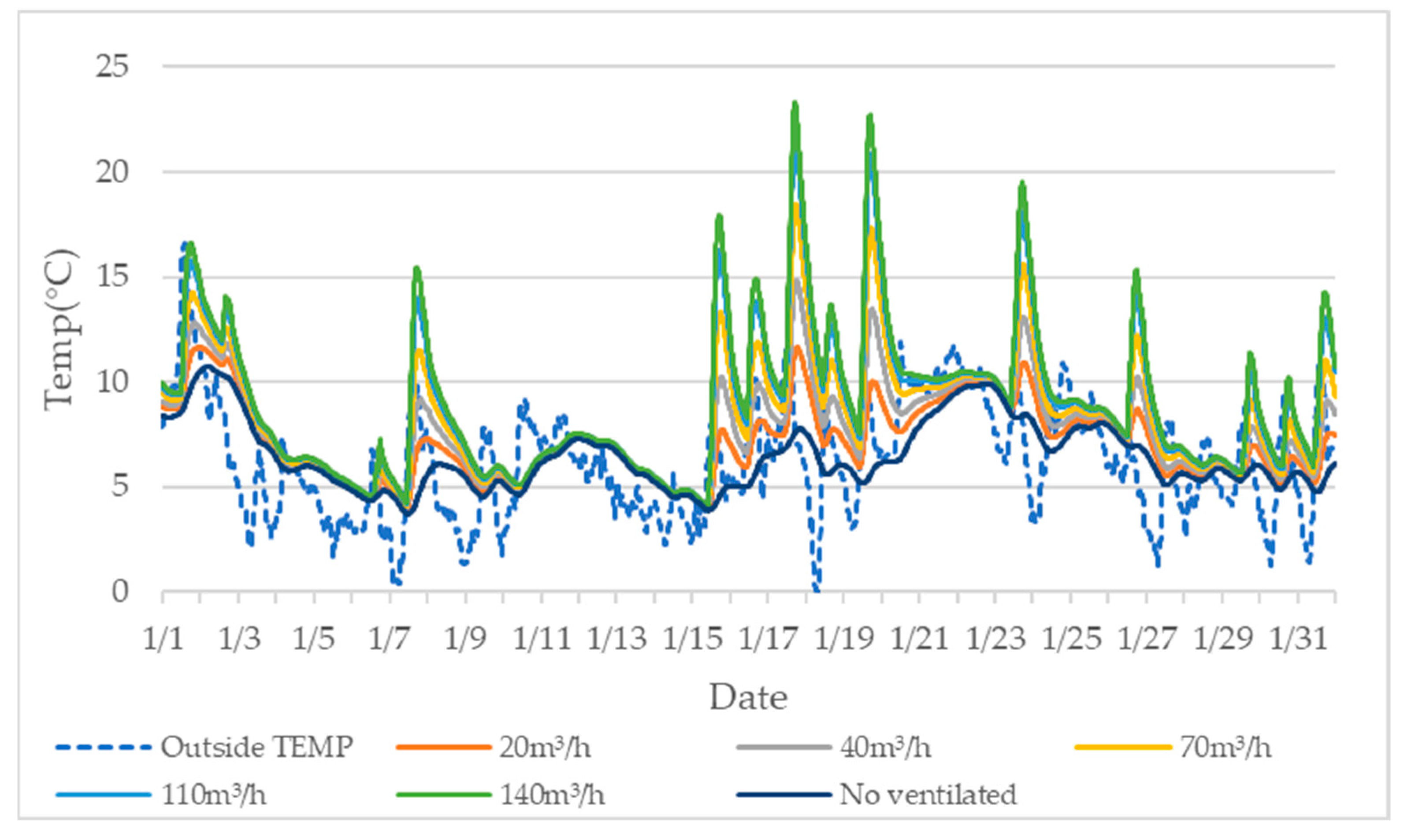
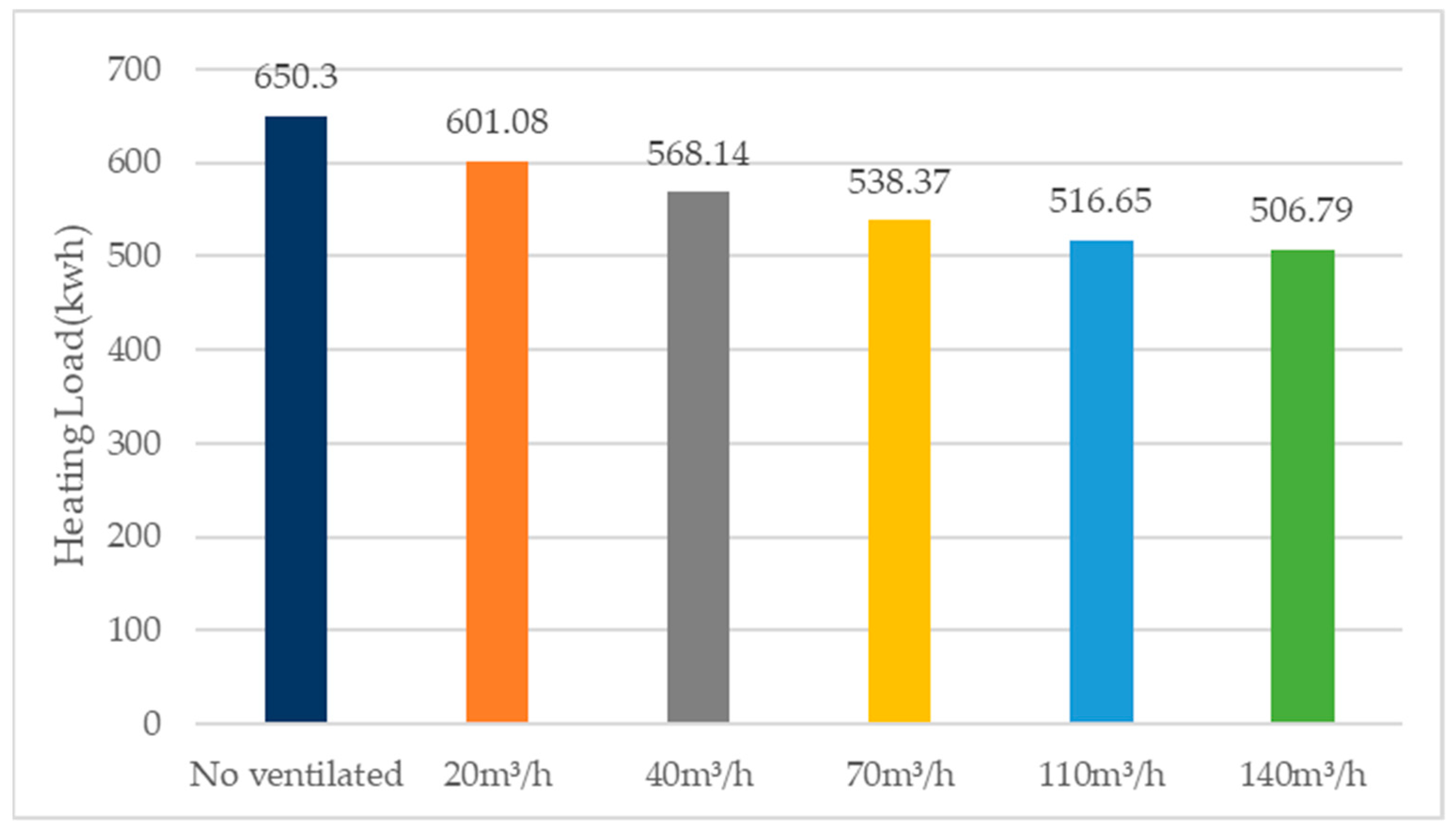
First, we conducted a preliminary analysis of the indoor temperature changes throughout the year without air conditioning. Take January as an example in Figure 12, we found that the air circulation effectively increased the indoor temperature. When the ventilation rates were 140 m3/h, the indoor temperature without heating remained the highest. It could be preliminarily judged, in this range, that the greater the amount of ventilation in the indoor air circulation, the higher the efficiency of the Trombe walls.
When comparing the annual air conditioning load in the heating condition (in Figure 13), the results were consistent with the indoor temperature change in the unconditioned condition. In comparison, it was found that under the condition of ventilation below 140 m3/h, the greater the ventilation, the smaller the thermal load of the air conditioner. During the whole heating season, compared with the case of no air circulation, for ventilation of 20 m3/h, 40 m3/h, 70 m3/h, 110 m3/h, and 140 m3/h, the energy ratios saved were 7.6%, 12.6%, 17.2%, 20.5%, and 22%, respectively.
Even when operating at the highest ventilation of 140 m3/h, the DC fans increased energy consumption by only 0.08 kWhthroughout the day, which had almost no effect on the calculation result.
In the previous comparison, the most obvious energy saving effect was the change of window type. Regarding the types of glazing, it was found that the low-E double-glazed window theoretically had the best effect for reducing the building energy consumption. As for ventilation, after calculating the fan power, ventilation rates of 140 m3/h still had the best energy saving effect, as well as the use of 100 mm thickness for the massive wall (3.0% of the house floor area). The final simulated annual air conditioning heat load of this experimental house was about 270.84 kWh, and compared to the predicted heat load before optimization, more than 52.3% of the energy consumption could be saved throughout the year.
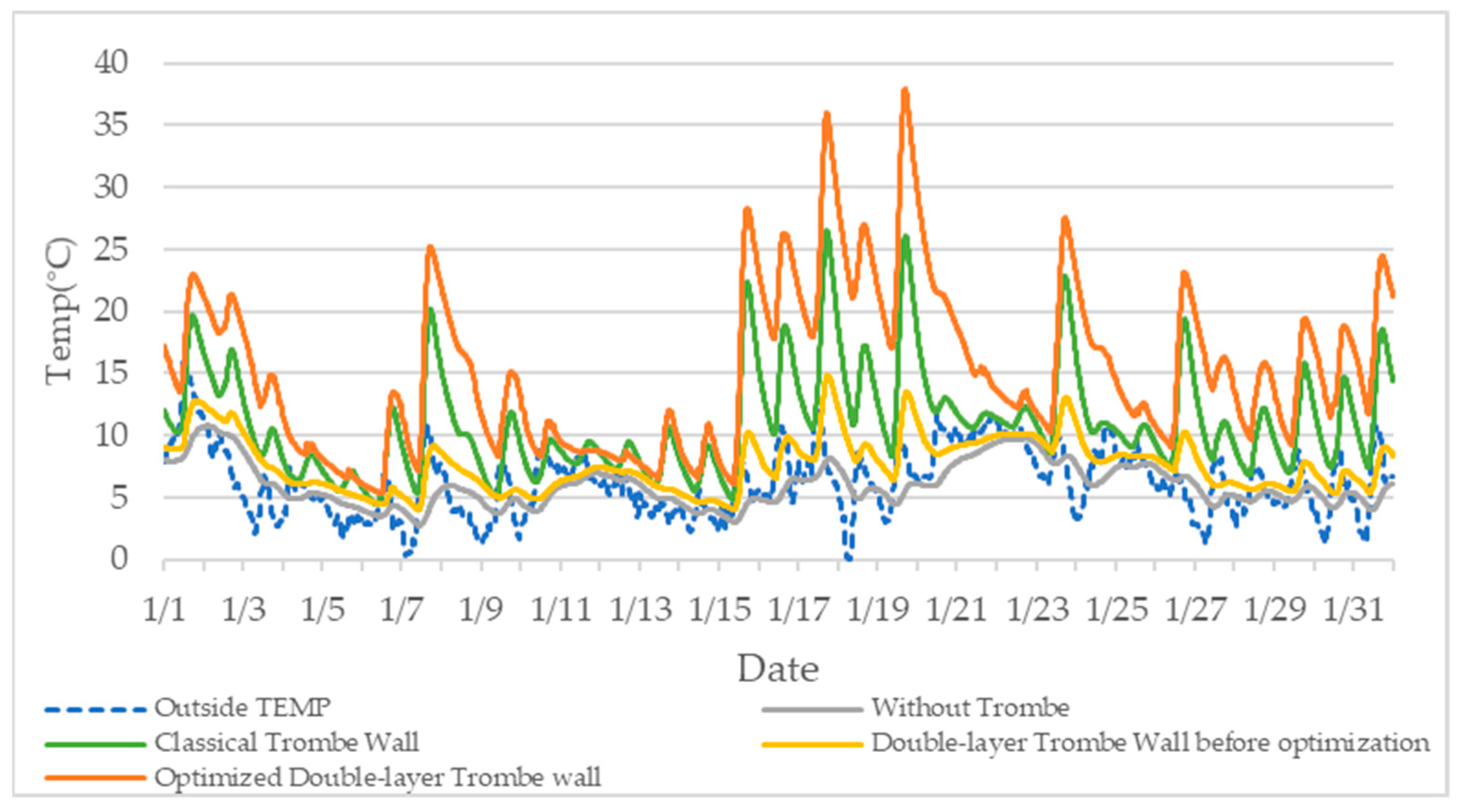
In response to the aforementioned problem of a low room temperature for this kind of composite double-layer Trombe wall in the state without air conditioning, after integrating the optimization factors, as shown in the Figure 14, in January, for example, the optimized composite double-layer Trombe wall had a significant overall improvement in room temperature compared to the pre-optimized room temperature, and in the daytime with sufficient solar radiation, the room temperature could reach a maximum of about 36.8 °C.
4. Discussion
The basic optimization idea of Trombe wall is to improve the efficiency of solar energy absorption and reduce the heat dissipation of the building. A composite double-layer Trombe wall, assisted by a temperature-controlled DC fan, can steadily and quickly transfer the heat from the higher temperature air layer to the lower temperature room, and also avoid the occurrence of the siphoning phenomenon. While the double wall setup is used for the low thermal resistance of the classical Trombe wall, this setup theoretically hinders the efficiency of heat transfer into the room during the daytime, which is confirmed by the simulation results without air conditioning; however, on the whole, this design is promising for research in combination with the air conditioning system to calculate the building heat load. However, it is preferable to achieve a lower energy consumption or even zero energy consumption. This is why experiments for optimization are necessary.
This experiment is based on the conclusions drawn from the simulation of a virtual model based on the construction of a real reference house. The calculated values of the experiment are all calculated under ideal conditions. The parameters used in the calculation are based on the fact that they can be quickly put into real-life use, so the research will subsequently verify the actual operation of the ideal model based on the scheme proposed by the experimental results. Although the basic module used for the experiment differs somewhat from the actual building rooms used by humans, and applying the Trombe wall to different rooms will produce different values, certain proportions and trends can still be calculated through the simulation. In future work, we will further investigate ventilation methods, optimal materials for massive wall, etc., and will introduce south-facing transmissible windows to calculate the optimal ratio of windows to Trombe wall, etc., according to actual conditions. Re-validation will be carried out using actual building renovation under feasible conditions. We will calculate the total benefit of the whole life cycle from an economic and engineering point of view, discuss its thermal comfort, etc.
5. Conclusions
This study mainly focuses on a new composite Trombe wall, which adds a layer of thermal insulation wall to the traditional Trombe wall to form two air layers. At the same time, pipes and air vents in the upper and lower areas are used to connect the two air layers and the room, so that the composite Trombe wall forms two air circulations as the inner and outer. The air circulation is forced to be stable and fast by using temperature-controlled DC fans. The study evaluates the thermal potential of this composite Trombe wall by using THERB for HAM software, which has been approved by the Japanese government as an evaluation method for annual heating and cooling load calculation methods. The following main results are drawn from the numerical simulations performed:
- A composite Trombe wall assisted by a temperature-controlled DC fan can achieve better energy savings compared to a classic Trombe wall with thermal air conditioning. However, the overall room temperature of the composite Trombe wall is smaller than that of the classical Trombe wall in the absence of air conditioning.
- The most obvious energy saving effect is the change of window type. Compared to single-glazing, double-glazing with a low-E layer is expected to save nearly 41.3% of the energy. It is expected to save nearly 41.3% of the annual heat load. Energy savings can also be achieved with ordinary multi-pane glass, with double and triple glazing saving 17.2% and 27.9% of the energy consumption, respectively.
- The thickness of the massive wall, i.e., the proportion of the area occupied by the massive wall, also affects the efficiency of the massive wall. Simulations show that a concrete massive wall percentage of about 3% of the room area is a better choice.
- Within a certain range, the higher the ventilation volume, the higher the heat load that can be saved. Under existing conditions, a ventilation volume of 140 m3/h can save 22% of energy compared to the case with no air circulation.
By integrating optimistic conditions, the annual thermal energy in winter is calculated to be 270.84 kWh, which can save nearly 52.3% of the thermal load compared to the pre-optimization period. It also greatly improves the overall room temperature without the effect of air conditioning. Therefore, the double-layer Trombe wall assisted by temperature-controlled DC fans is suitable for buildings in hot-summer and cold-winter regions of Japan during the winter heating period.
Author Contributions
Methodology, Y.Z. and Q.M.; software, Q.M.; formal analysis, Y.Z. and T.Z.; data curation, Y.Z. and T.Z.; writing—original draft preparation, Y.Z.; writing—review and editing, T.Z. and H.F.; supervision, H.F. All authors have read and agreed to the published version of the manuscript.
Funding
This research received no external funding.
Institutional Review Board Statement
Not applicable.
Informed Consent Statement
Not applicable.
Data Availability Statement
The data presented in this study are available on request from the authors.
Acknowledgments
We are grateful to Akihito Ozaki (Kyushu University, Japan) and Myonghyang Lee (Ritsumeikan University, Japan) for their valuable suggestions. The authors would like to express their heartfelt acknowledgements to THERB software.
Conflicts of Interest
The authors declare no conflict of interest.
References
- Chan, H.Y.; Riffat, S.B.; Zhu, J. Review of passive solar heating and cooling technologies. Renew. Sustain. Energy Rev. 2010, 14, 781–789. [Google Scholar] [CrossRef]
- Hu, Z.; He, W.; Ji, J.; Zhang, S. A review on the application of Trombe wall system in buildings. Renew. Sustain. Energy Rev. 2016, 70, 976–987. [Google Scholar] [CrossRef]
- Ürge-Vorsatz, D.; Cabeza, L.F.; Serrano, S.; Barreneche, C.; Petrichenko, K. Heating and cooling energy trends and drivers in buildings. Renew. Sustain. Energy Rev. 2015, 41, 85–98. [Google Scholar] [CrossRef] [Green Version]
- Lee, H.; Ozaki, A.; Lee, M. Energy saving effect of air circulation heat storage system using natural energy. Build. Environ. 2017, 124, 104–117. [Google Scholar] [CrossRef]
- Chel, A.; Nayak, J.; Kaushik, G. Energy conservation in honey storage building using Trombe wall. Energy Build. 2008, 40, 1643–1650. [Google Scholar] [CrossRef]
- Liu, Y.W.; Feng, W. Integrating Passive Cooling and Solar Techniques into the Existing Building in South China. Adv. Mater. Res. 2011, 368–373, 3717–3720. [Google Scholar] [CrossRef]
- Naboni, E.; Malcangi, A.; Zhang, Y.; Barzon, F. Defining The Energy Saving Potential of Architectural Design. Energy Procedia 2015, 83, 140–146. [Google Scholar] [CrossRef] [Green Version]
- Denzer, A. The solar house: Pioneering sustainable design. Arts 2013, 3, 303–306. [Google Scholar]
- Daniel, A. A House in the Sun: Modern Architecture and Solar Energy in the Cold War; Oxford University Press: Oxford, UK, 2016. [Google Scholar]
- Mazria, E. The Passive Solar Energy Book; Rodale Press: Emmaus, PA, USA, 1979; ISBN 0-87857-237-6. [Google Scholar]
- Sergei, K.; Shen, C.; Jiang, Y. A review of the current work potential of a trombe wall. Renew. Sustain. Energy Rev. 2020, 130, 109947. [Google Scholar] [CrossRef]
- Shen, J.; Lassue, S.; Zalewski, L.; Huang, D. Numerical study of classical and composite solar walls by TRNSYS. J. Therm. Sci. 2007, 16, 46–55. [Google Scholar] [CrossRef]
- Briga-Sá, A.; Martins, A.; Boaventura-Cunha, J.; Lanzinha, J.C.; Paiva, A. Energy performance of Trombe walls: Adaptation of ISO 13790:2008(E) to the Portuguese reality. Energy Build. 2014, 74, 111–119. [Google Scholar] [CrossRef]
- Agrawal, B.; Tiwari, G.N. Building Integrated Photovoltaic Thermal Systems: For Sustainable Developments; Royal Society of Chemistry: London, UK, 2011. [Google Scholar]
- Kundakci Koyunbaba, B.; Yilmaz, Z. The comparison of Trombe wall systems with single glass, double glass and PV panels. Renew Energy 2012, 45, 111–118. [Google Scholar] [CrossRef]
- Irshad, K.; Habib, K.; Thirumalaiswamy, N. Energy and cost analysis of photo voltaic trombe wall system in tropical climate. Energy Procedia 2014, 50, 71–78. [Google Scholar] [CrossRef] [Green Version]
- Zhou, L.; Huo, J.; Zhou, T.; Jin, S. Investigation on the thermal performance of a composite Trombe wall under steady state condition. Energy Build. 2020, 214, 109815. [Google Scholar] [CrossRef]
- Abed, A.A.; Ahmed, O.K.; Weis, M.M.; Ali, Z.H. Influence of glass cover on the characteristics of PV/trombe wall with BI-fluid cooling. Case Stud. Therm. Eng. 2021, 27, 101273. [Google Scholar] [CrossRef]
- Pourghorban, A.; Asoodeh, H. The impacts of advanced glazing units on annual performance of the Trombe wall systems in cold climates. Sustain. Energy Technol. Assess. 2022, 51, 101983. [Google Scholar] [CrossRef]
- Lichołai, L.; Starakiewicz, A.; Krasoń, J.; Miąsik, P. The Influence of Glazing on the Functioning of a Trombe Wall Containing a Phase Change Material. Energies 2021, 14, 5243. [Google Scholar] [CrossRef]
- Du, L.; Ping, L.; Yongming, C. Study and analysis of air flow characteristics in Trombe wall. Renew. Energy 2020, 162, 234–241. [Google Scholar] [CrossRef]
- Liu, H.; Li, P.; Yu, B.; Zhang, M.; Tan, Q.; Wang, Y.; Zhang, Y. Contrastive Analysis on the Ventilation Performance of a Combined Solar Chimney. Appl. Sci. 2021, 12, 156. [Google Scholar] [CrossRef]
- Briga-Sá, A.; Paiva, A.; Lanzinha, J.-C.; Boaventura-Cunha, J.; Fernandes, L. Influence of Air Vents Management on Trombe Wall Temperature Fluctuations: An Experimental Analysis under Real Climate Conditions. Energies 2021, 14, 5043. [Google Scholar] [CrossRef]
- Ji, J.; Yi, H.; Pei, G.; Jiang, B.; He, W. Study of PV-Trombe wall assisted with DC fan. Build. Environ. 2007, 42, 3529–3539. [Google Scholar] [CrossRef]
- Ma, Q.; Fukuda, H.; Kobatake, T.; Lee, M. Study of a Double-Layer Trombe Wall Assisted by a Temperature-Controlled DC Fan for Heating Seasons. Sustainability 2017, 9, 2179. [Google Scholar] [CrossRef] [Green Version]
- Ma, Q.; Fukuda, H.; Wei, X.; Hariyadi, A. Optimizing energy performance of a ventilated composite Trombe wall in an office building. Renew. Energy 2018, 134, 1285–1294. [Google Scholar] [CrossRef]
- Ozaki, A.; Lee, M.; Kuma, Y. Numerical simulation on hygrothermal environment of whole buildings taking into account complete ham features. In Proceedings of the 12th International Building Performance Simulation Association Conference, Sydney, Australia, 14–16 November 2011; pp. 2156–2163. [Google Scholar]
- Kumaran, M.K. Architectural Institute of Japan, International Energy Agency Energy Conservation in Buildings and Community Systems IEA ANNEX 24 Heat, Air and Moisture Transfer through New and Retrofitted Insulated Envelope Parts (Hamtie) Final Report Volume 3 TASK 3: Material Properties; Maruzen Publishing: Tokyo, Japan, 2001; p. 23. [Google Scholar]
- Ozaki, A.; Watanabe, T.; Takase, S. Simulation software of the hydrothermal environment of buildings based on detailed thermodynamic models. In Proceedings of the eSim 2004 Canadian Conference 17 on Building Energy Simulation, Vancouver, BC, Canada, 9–11 June 2004; pp. 45–54. [Google Scholar]
- Ozaki, A.; Tsujimaru, T. Prediction of hygrothermal environment of buildings based upon combined simulation of heat and moisture transfer and airflow. J. Int. Build. Perform. Simul. Assoc. 2006, 16, 30–37. [Google Scholar]
Figure 1.
The reference house: (a) the south elevation of the reference house; (b) the massive wall of Trombe wall.
Figure 1.
The reference house: (a) the south elevation of the reference house; (b) the massive wall of Trombe wall.

Figure 2.
Trombe wall section of the south elevation of the models: (a) the classical Trombe wall and its air circulation; (b) the new type composite Trombe wall and its air circulation.
Figure 2.
Trombe wall section of the south elevation of the models: (a) the classical Trombe wall and its air circulation; (b) the new type composite Trombe wall and its air circulation.

Figure 3.
The outside temperature and solar radiation measured from 1 January to 13 January 2020.

Figure 4.
Comparison of the measured data and the simulation data of the indoor temperature from 3 January to 12 January 2020.
Figure 4.
Comparison of the measured data and the simulation data of the indoor temperature from 3 January to 12 January 2020.

Figure 5.
Comparison of room temperature without heating of January.

Figure 6.
Comparison of air conditioning load with heating for the overall heating season.

Figure 7.
Comparison of room temperature with different types of glazing without heating for January.
Figure 7.
Comparison of room temperature with different types of glazing without heating for January.

Figure 8.
Comparison of Air conditioning load with different types of glazing with heating overall heating season.
Figure 8.
Comparison of Air conditioning load with different types of glazing with heating overall heating season.

Figure 9.
Comparison of room temperature with different thicknesses of massive walls without heating for January.
Figure 9.
Comparison of room temperature with different thicknesses of massive walls without heating for January.

Figure 10.
Heating load on 19 January and on 4 February: (a) 19 January, a sunny day with high solar radiation during the day; (b) 4 February, a cloudy day with low solar radiation during the day.
Figure 10.
Heating load on 19 January and on 4 February: (a) 19 January, a sunny day with high solar radiation during the day; (b) 4 February, a cloudy day with low solar radiation during the day.

Figure 11.
Comparison of the air conditioning load for different thickness of the massive wall with heating for the overall heating season.
Figure 11.
Comparison of the air conditioning load for different thickness of the massive wall with heating for the overall heating season.

Figure 12.
Comparison of room temperature with different ventilation rates without heating for January.
Figure 12.
Comparison of room temperature with different ventilation rates without heating for January.

Figure 13.
Comparison of air conditioning loads with different ventilation rates for the overall heating season.
Figure 13.
Comparison of air conditioning loads with different ventilation rates for the overall heating season.

Figure 14.
Comparison of room temperature without heating for January.


Table 1.
Material and structure of the envelope of the reference house.
| Construction | Material | Thickness (m) |
|---|---|---|
| Exterior wall | Styrofoam board | 0.030 |
| Japanese fir | 0.105 | |
| galvalume steel plate | 0.002 | |
| Floor | Styrofoam board | 0.030 |
| Japanese fir | 0.105 | |
| Roof/Ceiling | Styrofoam board | 0.030 |
| Japanese fir | 0.105 | |
| galvalume steel plate | 0.002 | |
| Ground | Soil | ----- |
Table 2.
Material and structure of the Trombe wall of the reference house.
| Construction | Material | Thickness (m) |
|---|---|---|
| Massive wall | Concrete brick | 0.100 |
| Air layer | Air | ----- * |
| Glazing surface | Glass (single layer) | 0.003 |
* The gap between the massive wall and the glazing surface is 0.210 m.
Table 3.
Properties of each material.
| Material | Thickness (m) | Thermal Conductivity (W/m K) | Density (kg/m3) | Specific Heat Capacity (J/kg K) |
|---|---|---|---|---|
| Japanese fir | 0.105 | 0.099 | 364.0 | 2150 |
| Styrofoam board | 0.030 | 0.036 | 27.0 | 1100 |
| Air layer | ----- | 0.022 | 1.2 | 1000 |
| Galvalume steel plate | 0.002 | 44.200 | 3690.0 | 196 |
| Concrete brick | 0.100 | 1.600 | 1750.0 | 840 |
| Glass | 0.003 | 0.780 | 2540.0 | 770 |
Publisher’s Note: MDPI stays neutral with regard to jurisdictional claims in published maps and institutional affiliations. |
© 2022 by the authors. Licensee MDPI, Basel, Switzerland. This article is an open access article distributed under the terms and conditions of the Creative Commons Attribution (CC BY) license (https://creativecommons.org/licenses/by/4.0/).
Share and Cite
MDPI and ACS Style
Zhu, Y.; Zhang, T.; Ma, Q.; Fukuda, H. Thermal Performance and Optimizing of Composite Trombe Wall with Temperature-Controlled DC Fan in Winter. Sustainability 2022, 14, 3080. https://doi.org/10.3390/su14053080
AMA Style
Zhu Y, Zhang T, Ma Q, Fukuda H. Thermal Performance and Optimizing of Composite Trombe Wall with Temperature-Controlled DC Fan in Winter. Sustainability. 2022; 14(5):3080. https://doi.org/10.3390/su14053080
Chicago/Turabian StyleZhu, Yuewei, Tao Zhang, Qingsong Ma, and Hiroatsu Fukuda. 2022. "Thermal Performance and Optimizing of Composite Trombe Wall with Temperature-Controlled DC Fan in Winter" Sustainability 14, no. 5: 3080. https://doi.org/10.3390/su14053080
Note that from the first issue of 2016, this journal uses article numbers instead of page numbers. See further details here.