Article

Influence of Type of Sleeper–Ballast Interface on the Shear Behaviour of Railway Ballast: An Experimental and Numerical Study

by
Sinniah Karuppiah Navaratnarajah
*,
Henpita Gamage Sushan Mayuranga
and
Somasundaraiyer Venuja
Department of Civil Engineering, Faculty of Engineering, University of Peradeniya, Peradeniya 20400, Sri Lanka
*
Author to whom correspondence should be addressed.
Sustainability 2022, 14(24), 16384; https://doi.org/10.3390/su142416384
Submission received: 25 October 2022 / Revised: 2 December 2022 / Accepted: 5 December 2022 / Published: 7 December 2022
(This article belongs to the Special Issue Sustainability and Innovation in Transport Infrastructure Geotechnics)

Abstract

:
The shear resistance at the sleeper–ballast interface of a ballasted track is an important contributor in maintaining track stability under faster and heavier axle loads where the ballast undergoes significant lateral sliding. Different types of sleeper–ballast interfaces based on the type of sleeper arrangements, such as concrete sleepers, timber sleepers, and under sleeper pads (USPs) attached to the concrete sleepers influence the lateral stability of railway tracks. Therefore, in this study the shear and degradation behaviour of ballast at concrete–ballast, timber–ballast, and USP–ballast interfaces were examined in the laboratory using large-scale direct shear tests under 60 kPa normal stress. The use of waste materials in the construction of civil infrastructure is gaining a lot of interest in the engineering community. Therefore, in addition to commercial USPs manufactured using raw materials, recycled USPs manufactured from granulates of end-of-life rubber tyres were also tested in this study. The discrete element modelling (DEM) approach was used to predict the shear behaviour of ballast at 30, 90, 120, 150, and 180 kPa normal stresses. The bonded particle model (BPM) was adopted in the DEM to simulate the effects of particle breakage during shearing. The results exhibited that both commercial and recycled USPs significantly improve the shear resistance at the sleeper–ballast interface while reducing particle degradation compared to concrete and timber sleeper interfaces.

1. Introduction

Due to the advancement of faster and heavier trains, railways have become the most preferred mode of transportation globally providing a reliable, ecologically friendly, efficient, and cost-effective service to passengers as well as transportation of commodities. When focusing on railway infrastructure, ballasted rail corridors are employed by many railway authorities due to their numerous benefits, including low initial construction cost, abundance of raw materials, ease of construction, etc. [1,2,3]. The ballasted track is a layered track system in which the interface friction at different layers and self-interlocking of the ballast layer facilitates maintaining track stability [4,5]. In this sense, the shear resistance at the sleeper–ballast interface is crucial, as it holds the track superstructure and the substructure together. At present, various sleeper arrangements such as timber sleepers, concrete sleepers, steel sleepers, and under sleeper pads (USPs) attached to concrete sleepers can be identified in different tracks.
The use of timber sleepers in ballasted tracks was popular in the early stages of railway history due to several advantages, such as low cost and ease of production, easy handling without damage, suitability for all types of ballast, greater shock and vibration absorbance, and increased resiliency. Nevertheless, owing to their shorter life span (about 12 to 15 years), restricted structural strength, and susceptibility to fire, railway authorities focused on employing a more robust material such as concrete sleepers [6]. Concrete sleepers are more durable (may last up to 50 years), have better resistance to fire and bad weather, and exhibit greater structural strength. However, due to their heavy weight, they are difficult to handle, and after cracking the sleeper must be replaced rather than repaired. In addition, the resiliency of the track structure is also significantly reduced due to the high stiffness of concrete sleepers. In recent times, the use of USPs attached to concrete sleepers in ballasted tracks has become popular among several railway authorities, with the primary goal of reducing ballast–sleeper contact stress and ground-borne vibration [7,8,9,10]. USPs create a softer surface on which ballast particles can be embedded, increasing the sleeper–ballast contact area and thereby reducing ballast pressure [7,11,12]. It also brings back the resiliency of the track lost due to stiffer concrete.
As a result of the presence of these different sleeper arrangements, sleeper–ballast interface resistance may alter significantly, affecting track stability. Hence it is imperative to evaluate the shear behaviour at the sleeper–ballast interface in different sleeper arrangements. Several studies have been conducted to evaluate the shear behaviour of both fresh and fouled ballast utilizing the large-scale direct shear test [13,14,15]. Nevertheless, there is a lack of investigation exploring the shear behaviour of ballast with different interfaces. Additionally, the use of USPs manufactured from waste rubber tyres is an ideal solution that will reduce their volume in landfills and contribute to more efficient land use, especially in densely populated and expensive metropolitan regions. This also brings value to waste materials and offers a lesser environmental impact while preserving the mechanical properties of the material in its specific usage [9]. As a result, it is beneficial to investigate the influence of USPs made of recycled tyres on the shear behaviour of ballast at the sleeper–ballast interface. Consequently, this study explores shear behaviour at the sleeper–ballast interface, considering different sleeper configurations.
In this study, large-scale direct shear tests were conducted to evaluate the shear behaviour at the sleeper–ballast interface. Three different sleeper configurations were considered, including timber sleepers, concrete sleepers, and USPs attached to concrete sleepers. Two types of USPs were considered, including commercial USPs manufactured using raw materials and recycled USPs manufactured using the granulates of waste rubber tyres. Additionally, the shear behaviour of the ballast–ballast interface was tested for comparison of results and calibration of numerical models. All laboratory tests were conducted under 60 kPa normal stress, representing the pressure on the top surface of the ballast layer due to the static load from a commuter train [16].
The discrete element method (DEM) is a powerful and widely accepted numerical tool used to predict the behaviour of granular materials. It also reduces the high material and labour costs associated with conducting a number of large-scale laboratory tests. Hence, 3D numerical models were developed in this study using DEM to simulate large-scale direct shear tests with different sleeper arrangements in order to investigate the shear behaviour of ballast under different normal stresses. Breakable ballast particles were created in DEM by capturing the shape of ballast aggregates using 3D scanning of actual ballast particles. The models were calibrated and validated with experimental results under 60 kPa normal stress. For verification of the applicability of validated models for other normal stresses, a large-scale direct shear test was conducted under 30 kPa normal stress for the ballast–ballast interface sample. Then, a parametric study was carried out at different normal stresses such as 30, 90, 120, 150, and 180 kPa for all test configurations. Based on the results, non-linear Mohr–Coulomb failure envelopes were developed to obtain the friction angles for each sleeper interface arrangement. The results of this study will support railway authorities in comparing the various types of sleeper arrangements used in ballasted tracks in terms of shear and degradation response of ballast and accommodate the appropriate type of sleeper arrangement. Additionally, extensive research can be conducted to investigate the means of increasing sleeper–ballast interface resistance in order to improve track stability.

2. Experimental Study
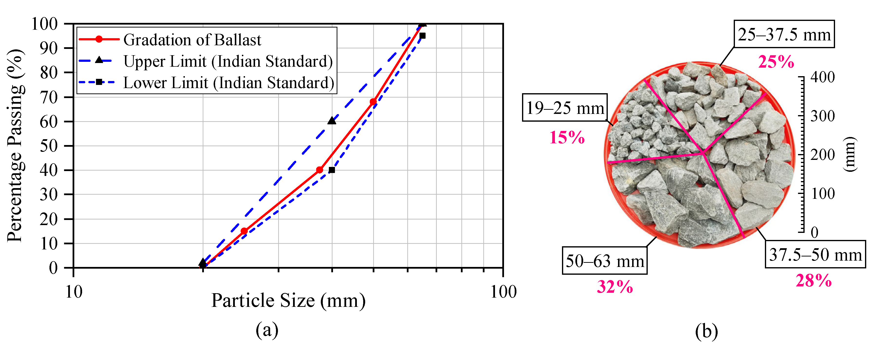
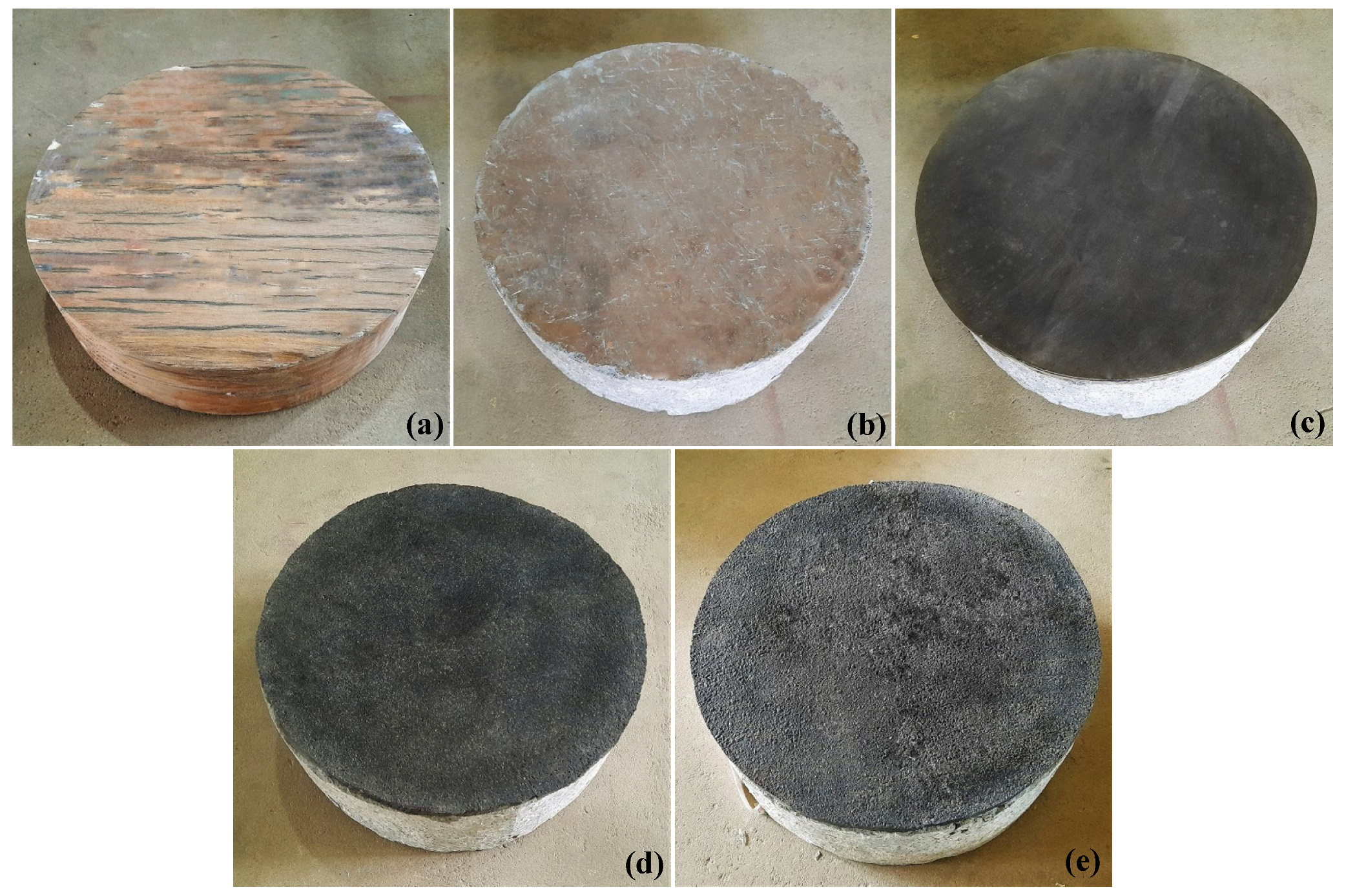
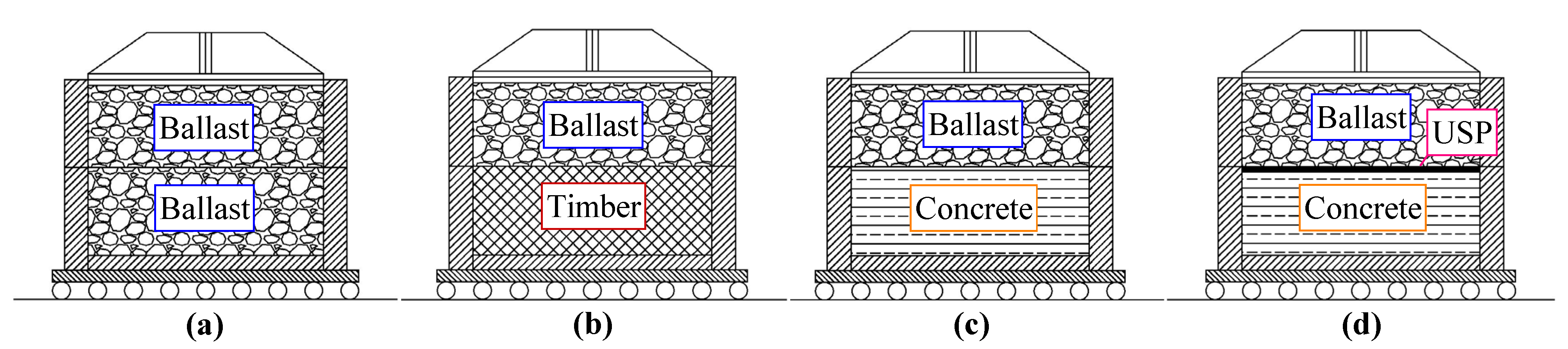
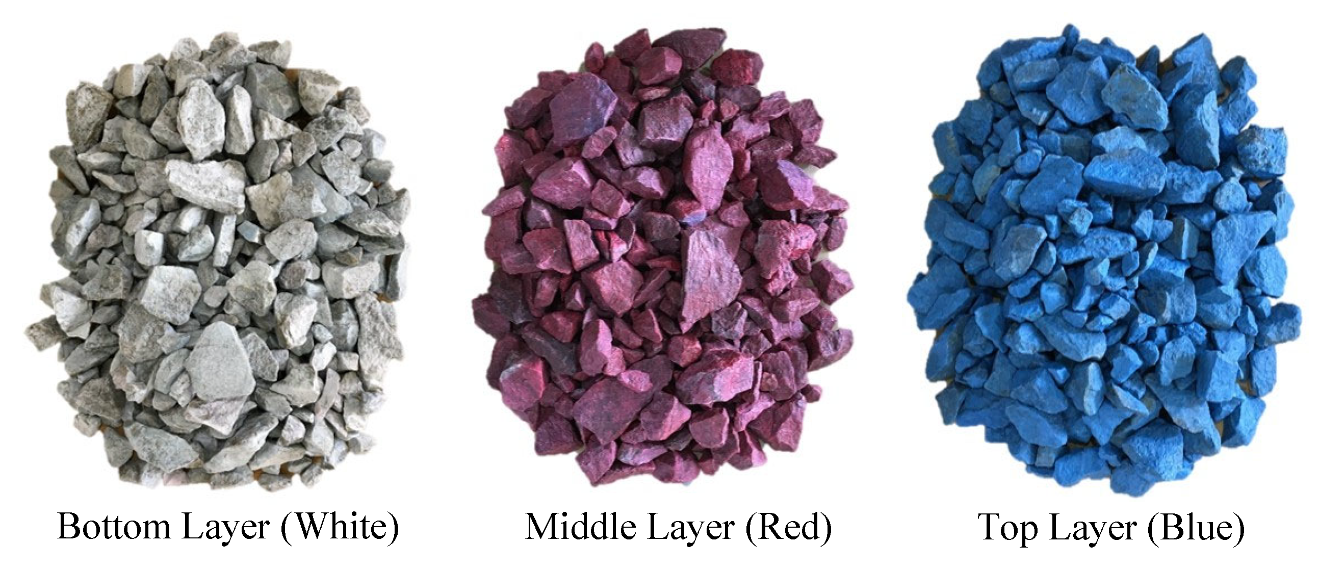
2.1. Test Materials

The fresh ballast material typically used in ballasted rail tracks in Sri Lanka was collected from the Boyagama quarry near Peradeniya City. The parent rock type of the ballast in this quarry was recognized as biotite gneiss. The collected ballast material was washed and air-dried to eliminate the impurities and fine soil particles that adhere to ballast aggregates. The bulk density and specific gravity of the fresh ballast determined using laboratory experiments according to the ISO 20290-1:2021 [17] standard specification were 1549 kg/m3 and 2.69, respectively. Sieve analysis was carried out to separate ballast aggregates into 4 different size groups, 19–25, 25–37.5, 37.5–50, and 50–63 mm. The test samples were prepared by mixing each sieved size of ballast aggregates according to the defined particle size distribution (PSD), as depicted in Figure 1a, which lies between the upper and lower limits of Indian standard gradation of ballast, widely adopted by the Department of Railways, Sri Lanka. Figure 1b shows the percentages of each sieved size group in a prepared test sample.
In this study, timber and concrete were used as sleeper materials. A timber sleeper typically used in railway tracks was obtained from the Gampola Railway Unit of the Department of Railways, Sri Lanka. From that, a cylindrical timber sleeper specimen with 400 mm diameter and 150 mm height was cut and prepared. The compressive strength of concrete used for the concrete sleeper was 60 MPa, and it was cast in the laboratory with the same dimensions as the timber sleeper.
Two types of USPs were adopted in this study; USPs manufactured from raw materials (USP_Raw) and USPs manufactured from the granulates of waste rubber tyres, which can be identified as recycled USPs (USP_RCL). Here, one sample of USP_Raw was tested while two different samples of USP_RCL were tested, representing commercially manufactured (USP_RCL#1) and locally manufactured (USP_RCL#2) USPs. A circular USP with a 400 mm diameter was attached to the concrete sleeper using epoxy glue and kept for a minimum of 24 h to achieve the required bond strength. The photographs of 5 different sleeper arrangements are shown in Figure 2, while the material properties of USPs as per the manufacturers’ specifications are given in Table 1.

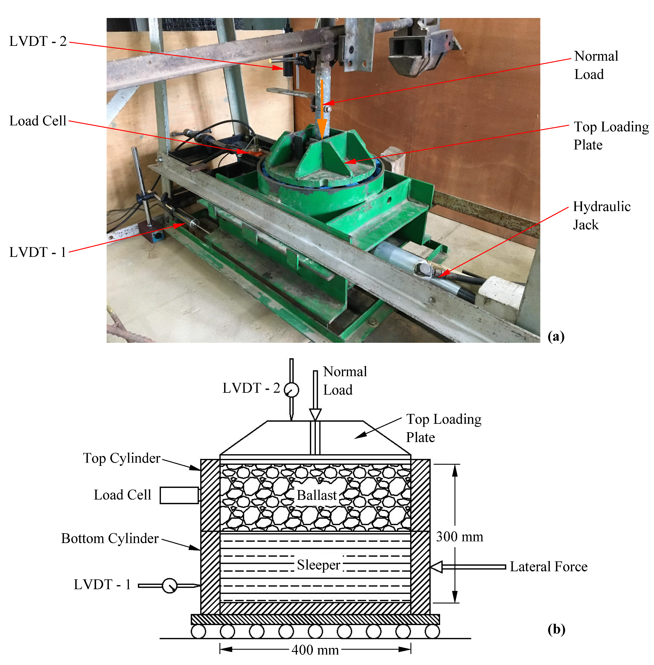
2.2. Large-Scale Direct Shear Apparatus

The large-scale direct shear apparatus shown in Figure 3a was designed and built at the Geotechnical Engineering Laboratory of the University of Peradeniya, Sri Lanka for conducting direct shear tests on full-size railway ballast. Figure 3b shows a schematic diagram of the large-scale direct shear apparatus. The apparatus has a circular shear plane, and it can accommodate a 400 mm diameter and 300 mm height test specimen. The dimensions of the test specimen were chosen to eliminate the sample size effect, where the diameter of the cylinder was maintained 6 times higher than the mean diameter of the maximum particle size [19,20]. The shear plane was maintained at 150 mm height of the test specimen, allowing the sample to separate into two equal portions using top and bottom cylinders, each having 150 mm depth. During the test, the movement of the top cylinder was restricted while the bottom cylinder was displaced laterally at a constant rate using the hydraulic jack attached to the system. The lever arm system was used to apply normal stress through the top loading plate, which rested on the test sample and was free to move vertically throughout the test. The reaction force on the top cylinder during shearing was measured by the load cell while the lateral displacement of the bottom cylinder and the vertical displacement of the top loading plate were measured by two linear variable differential transformers (LVDTs). The data from the load cell and two LVDTs were recorded by the laptop computer through a data logger.

2.3. Test Procedure

Six large-scale direct shear tests were performed under 60 kPa normal stress for six different interfaces: ballast–ballast, ballast–timber, ballast–concrete, ballast–USP_Raw, ballast–USP_RCL#1, and ballast–USP_RCL#2. Furthermore, an additional test was conducted under 30 kPa normal stress for the ballast–ballast interface, which was later used for the verification of validated numerical models. As shown in Figure 4, a 300 mm thick full-height ballast sample was used for the ballast–ballast interface test, whereas in the other cases the bottom half was filled with the timber sleeper, concrete sleeper, or USP-attached concrete sleeper, while the top half was filled with ballast. For the ballast–ballast interface test, the ballast material was placed in three equal 100 mm thick layers and each layer was compacted using a rubber-padded vibratory compactor to achieve the field density. In the other tests, only the top cylinder was filled with ballast in 50 mm and 100 mm thick layers, and each layer was compacted to achieve the field density.
For easy identification of different layers and particle breakage at the end of each test, ballast particles were coloured by applying a thin coat of non-oil-based spray paint. As depicted in Figure 5, three different colours (white, red, and blue) were used to differentiate the bottom, middle, and top layers in the ballast–ballast interface test. In the other tests, the 50 mm thick upper half of the middle layer and top layer were separated using red and blue colours, respectively. After filling the test cylinder, the top loading plate was placed on top of the ballast and the normal stress was applied using the lever arm system. During the test, a maximum 60 mm shear displacement, which corresponds to a 15% shear strain, was applied to the bottom cylinder at a constant rate of 4 mm/min.

2.4. Experimental Results

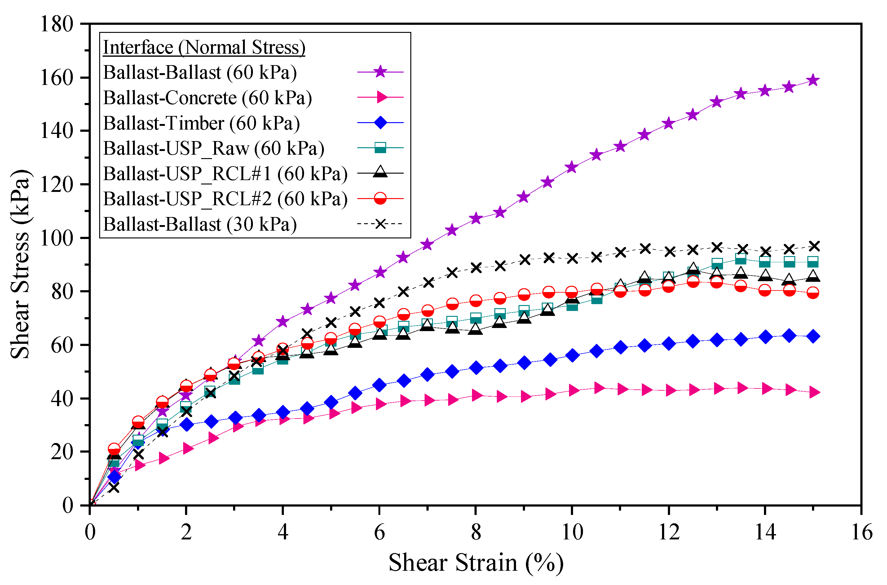
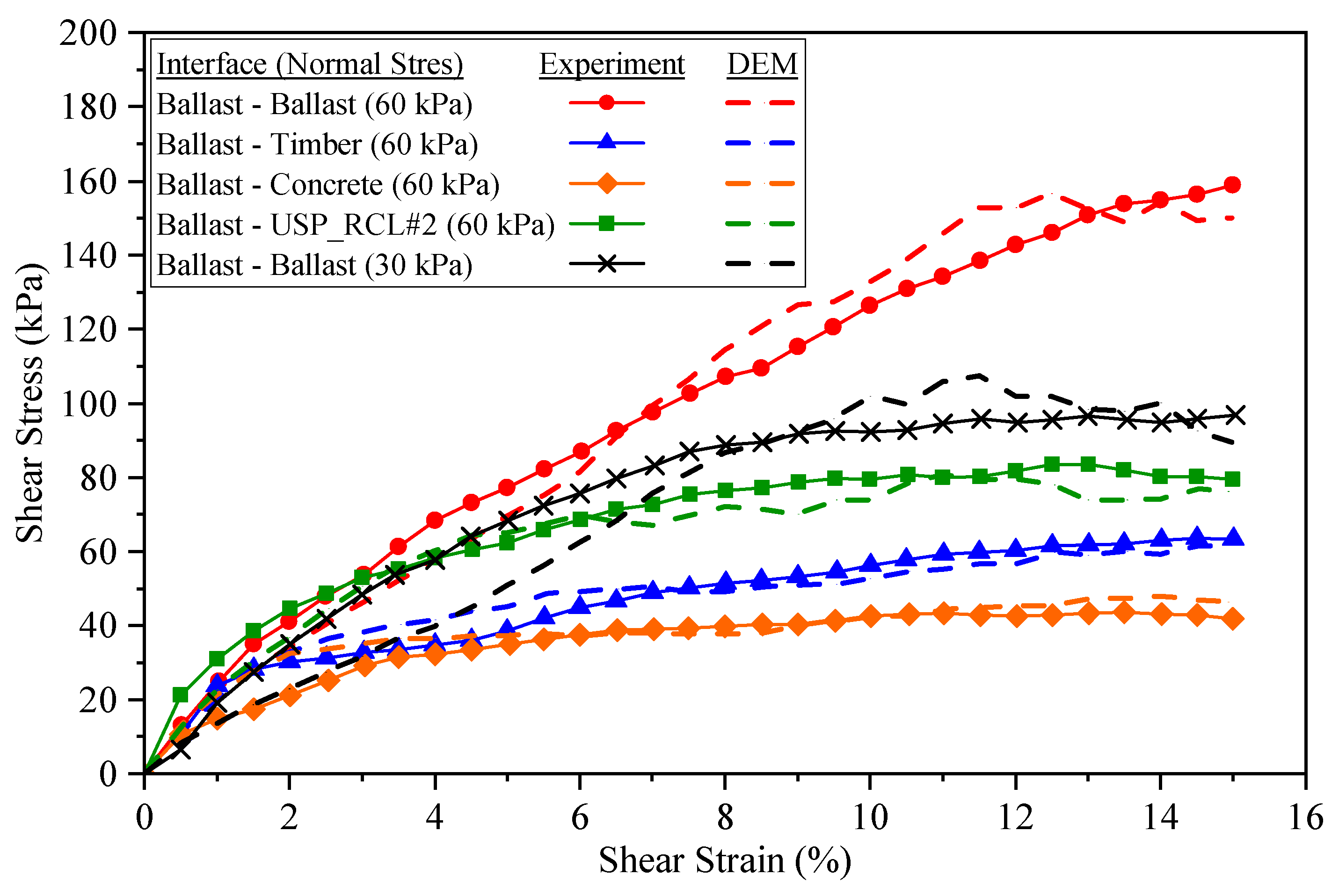
2.4.1. Shear Behaviour

The reaction force on the top cylinder obtained from the load cell was used to calculate the shear stress against the shear strain. Since the shear area (A) was changing with the shear displacement as shown in Figure 6, it was calculated using Equation (1), reported by Olson and Lai [21], where D and x denote the diameter of the test specimen and the shear displacement, respectively.
A = D 2 2 cos 1 x D x D 1 x D 2
Figure 7 depicts the variation of shear stress against shear strain for all six test samples under 60 kPa normal stress, together with the results of the ballast–ballast interface sample under 30 kPa normal stress. According to that, the ballast–ballast interface exhibited the highest shear stress followed by ballast–USP, ballast–timber, and ballast–concrete interfaces under 60 kPa normal stress.
The ballast–concrete and all ballast–USP interfaces showed peak shear stresses at about 13% shear strain and then slightly reduced and attained residual stresses. The other interfaces showed a gradual increase in shear stress up to 15% shear strain. With the normal stress increment from 30 kPa to 60 kPa for the ballast–ballast interface, an increment in shear stress was observed as expected due to induced particle interlocking and interaction. The self-interlocking ability of highly angular ballast aggregates, which provides higher resistance to shear, enabled the ballast–ballast interface to attain the highest shear stress variation compared to other interfaces under 60 kPa normal stress [14,22]. Since the hardness of the timber sleeper is comparatively less than that of the concrete sleeper, the timber sleeper exhibited relatively higher (about 56%) shear stress than the concrete sleeper. All three types of USPs employed in this study showed comparatively similar shear stress variation against shear strain. Under applied normal stress, ballast aggregates bedded very well into the USP surface and provided resistance to shearing under the lateral load, exhibiting higher shear stress than timber and concrete surfaces. Surface roughness is one of the main factors that influences shear behaviour at different sleeper interfaces [23]. As per the observation, the USP surface exhibited a higher surface roughness than the concrete surface. As a result of these facts, the application of USP enhanced shear stress at the sleeper–ballast interface by around 101% compared to that of the concrete interface. Manufacturing these USPs using recycled materials, such as granulates of end-of-life tyres, would be an added advantage as they perform competitively with USPs made of raw materials.

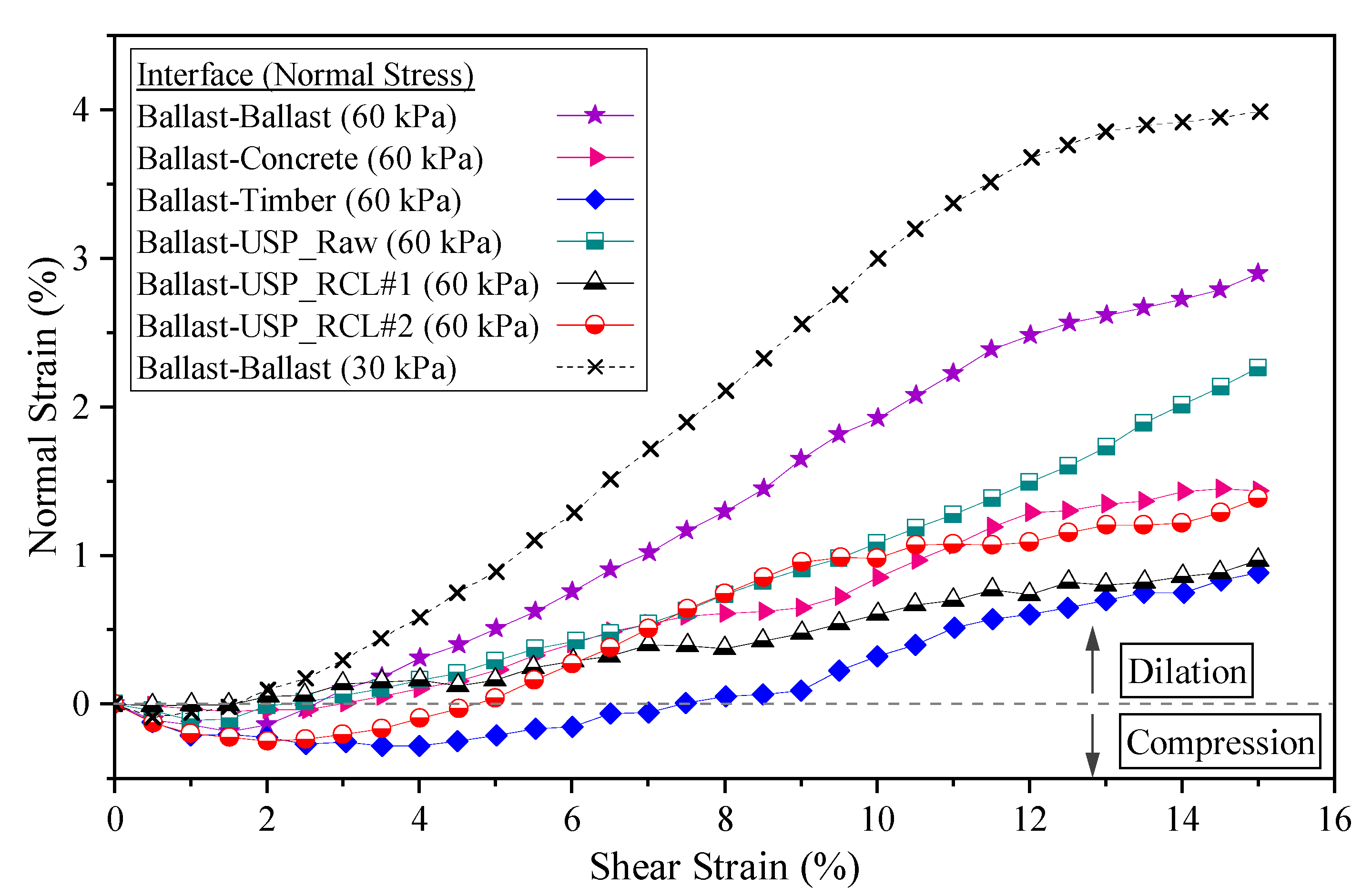
2.4.2. Compression/Dilation Behaviour

The variation of normal strain against shear strain for each test sample is shown in Figure 8. All the test samples exhibited initial compression as the ballast aggregates started to compress until they reached a threshold packing configuration, followed by dilation that was induced by particles rolling over each other. Under 60 kPa normal stress, the greatest dilation was observed in the ballast–ballast sample followed by the ballast–USP_Raw, ballast–concrete, ballast–USP_RCL#2, ballast–USP_RCL#1, and ballast–timber samples, respectively. Due to higher particle rolling and hence the rearrangement of particles, the ballast–ballast interface exhibited a higher dilation behaviour compared to other interfaces. When the normal stress was reduced to 30 kPa, the ballast–ballast interface exhibited higher dilation than under 60 kPa due to the reduction in the compressive force, which facilitated particle rearrangement. All the USP surfaces allowed ballast particles to embed into them at the shear plane, which facilitated other particles to roll over the embedded particles, showing the dilation behaviour. Similarly, the higher surface roughness of the concrete sleeper enabled particle rolling at the ballast–concrete interface and exhibited the dilation behaviour.
On the other hand, compared to the concrete sleeper, the timber sleeper had a relatively soft and smooth surface that facilitated the ballast particles slightly embedding into it. This promoted particle sliding (minimizing particle rolling) by scratching the timber surface under the shearing load, which resulted in lower dilation behaviour compared to other interfaces. This was evidenced from the scratch marks observed on the timber surface at the end of testing on the ballast–timber interface.

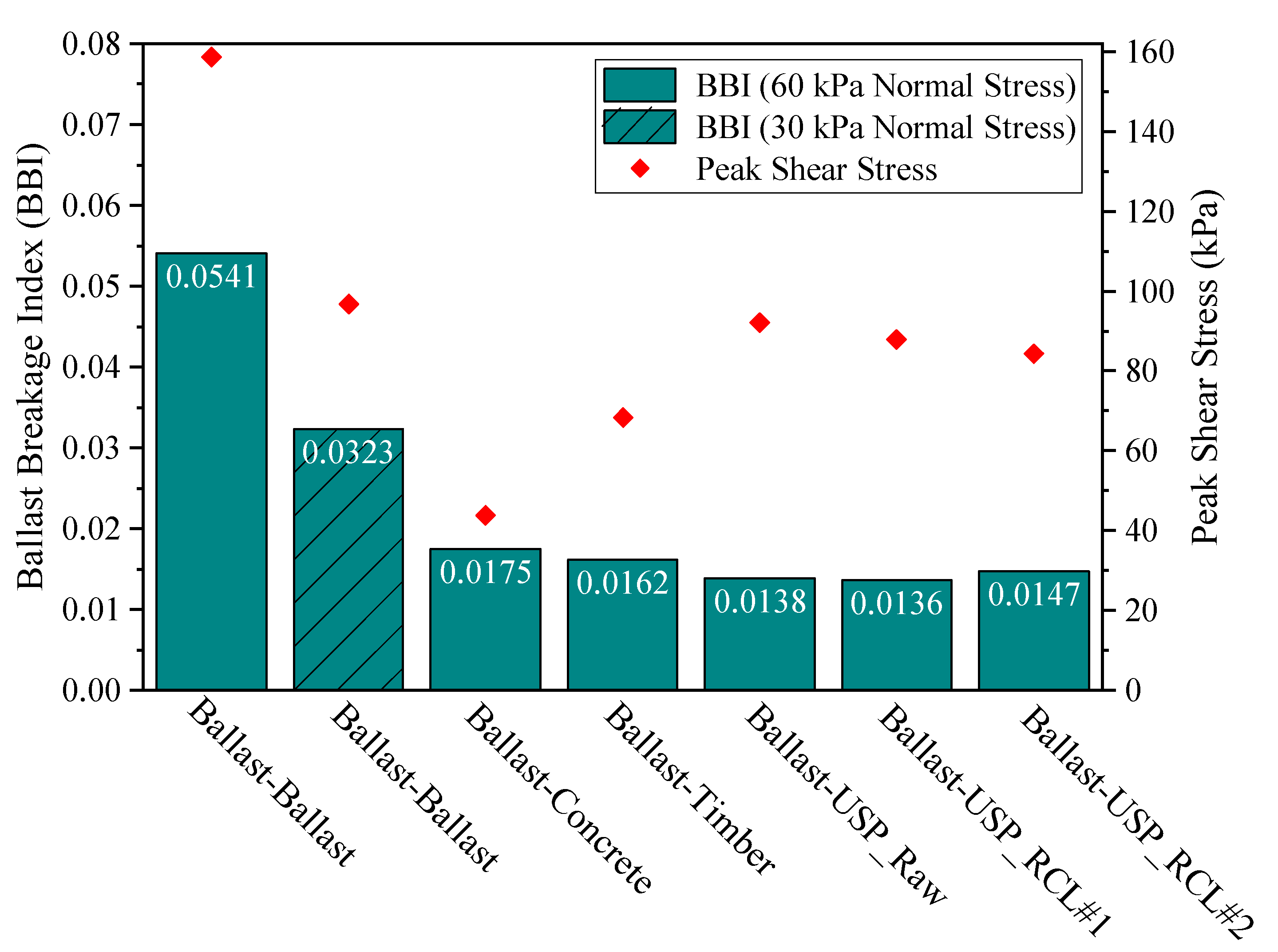
2.4.3. Ballast Breakage

Ballast breakage at different interfaces was evaluated in this study as it is a key parameter that influences the overall performance and settlement of the ballast layer. Among several methods suggested by different authors to quantify particle breakage, the ballast breakage index (BBI) suggested by Indraratna et al. [24] for railway ballast materials was adopted in this study. To calculate BBI, the sieve analysis was conducted at the end of each test to obtain the particle size distributions of ballast samples after shearing. Figure 9 summarizes the variation of BBI and peak shear for each interface. When comparing the effect of normal stress on the BBI of the ballast–ballast interface, a smaller BBI was observed for the lower normal stress of 30 kPa. This was due to lesser particle interaction under lower normal stress. According to the results for 60 kPa normal stress, the ballast–ballast interface exhibited the highest BBI as a result of intense interlocking between highly angular ballast particles, which leads to higher breakage of the angular corners of ballast particles. The second-highest BBI was reported for the ballast–concrete interface, followed by the ballast–timber and ballast–USP interfaces. When compared to the concrete surface, the timber surface provided comparatively softer contact with ballast particles, which exhibited less breakage than that of the concrete interface. As expected, all the ballast–USP interfaces showed the lowest BBI values as they allowed ballast particles to embed into the USP surface, providing a softer contact. An approximately 20% average reduction in BBI was found for the ballast–USP interfaces compared to the concrete–ballast interface. Therefore, from Figure 9 it is clear that the USPs manufactured from both raw materials and recycled materials reduced ballast degradation at the sleeper–ballast interface while enhancing the shear resistance.

3. Numerical Study

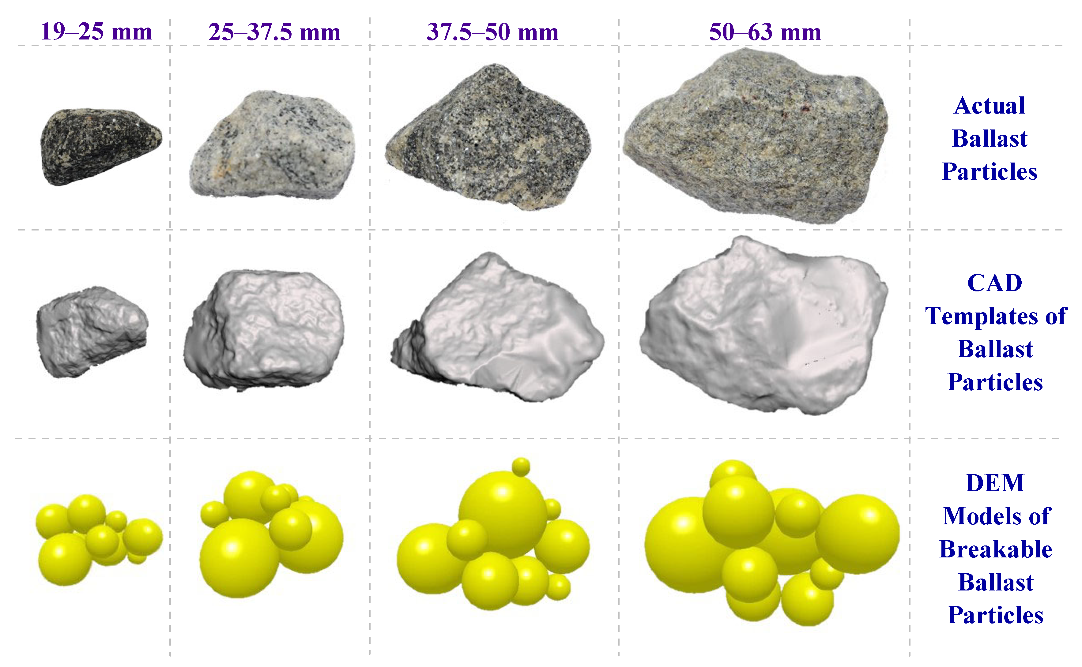
3.1. Discrete Element Modelling (DEM) of Ballast

Since the first introduction of DEM by Cundall and Strack [25], it has gained widespread acceptance as a viable numerical tool for solving engineering problems related to granular materials, notably in rock and powder mechanics, granular flows, and so on. DEM was successfully adopted by McDowell and Bolton [26] to study the micromechanical behaviour of granular ballast aggregates. Among other research studies, Lu and McDowell [27] employed DEM to simulate ballast abrasion due to cyclic loading, while Tutumluer et al. [28] developed a DEM model to study the deformational behaviour of track ballast under repetitive train loading. In addition, Ngo et al. [29] developed a DEM model of a large-scale direct shear test to investigate the effect of coal fouling on geogrid-stabilised railway ballast, in which the fouling material, geogrid, and ballast were modelled as discrete elements. Furthermore, many recent studies have also shown that DEM is capable of simulating railway ballast behaviour [30,31,32,33], including particle breakage [34,35,36,37,38], under various loading conditions.
Ballast particle breakage influences the shear stress variation obtained from the large-scale direct shear test. Hence, particle breakage was incorporated in the DEM simulation. The bonded particle model (BPM) is one of the popular methods used to simulate the breakage of granular particles in DEM. This was first formulated by Potyondy and Cundall [39]. In BPM, a breakable body is developed by bonding two or more spheres together using finite-sized glue bonds, in which a bond can break when the tangential and normal shear stress of the bond exceeds a predefined critical level. Once the bonds are created between the spheres in a breakable body, the forces and torques on the particles in both normal and tangential directions are set to zero and updated at every timestep according to
δ F n = v n S n A δ t
δ F t = v t S t A δ t
δ M n = ω n S t J δ t
δ M t = ω t S n J 2 δ t
where F, M, v, S, and ω denote force, moment, velocity, stiffness, and angular velocity, respectively, while the subscripts n and t denote normal and tangential directions, respectively. Here, A = π R B 2 and J = 0.5 π R B 4 , where RB denotes the radius of the finite-sized glue bonds. The criterion for bond breakage based on the normal and tangential shear stresses (σmax and τmax, respectively) is given by the following equations:
σ max < F n A + 2 M t J R B
τ max < F t A + M n J R B
In this study, the Hertz–Mindlin model was adopted as the contact model due to its efficient and accurate force calculation, and the bonded particle model (BPM) was adopted to simulate ballast particle breakage in direct shear tests.

3.2. Simulation of Ballast Particles

The shape of the angular ballast aggregate plays a significant role when simulating its behaviour in numerical modelling. Therefore, it is a novel practice to generate the approximately realistic shape of ballast particles in DEM using computer-aided design (CAD) templates of original ballast particles obtained through the 3D scanning technique. In this study, a library of CAD templates of various shapes of ballast particles was developed using 3D scanning, representing each size range of ballast according to the particle size distribution. Based on that, four selected ballast particles were generated in this study, using non-overlapping spheres representing the four different size ranges of ballast as shown in Figure 10. Since computational cost increases excessively with an increasing number of spheres, only around 12 spheres of various diameters were employed in each ballast particle while capturing the particle shape as much as possible. Bonds were introduced among the spheres of each particle based on the bonded particle model (BPM). Table 2 summarizes the mechanical properties of the ballast material, particle-to-particle interaction parameters, and bond strength parameters employed in this investigation. Since non-overlapping spheres cannot occupy the whole volume of an actual ballast particle, a higher value of ballast particle density was maintained to prevent mass conservation issues. The particle-to-particle interaction parameters and bond strength parameters were calibrated using large-scale direct shear test data.

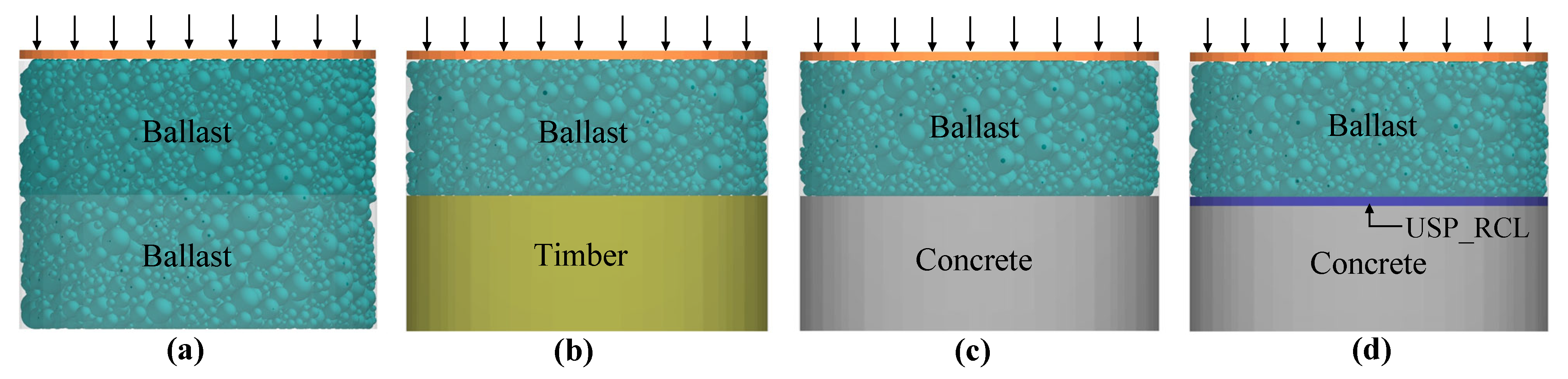
3.3. Simulation and Validation of Large-Scale Direct Shear Test

Four different numerical models of large-scale direct shear tests were developed, representing ballast–ballast, ballast–timber, ballast–concrete, and ballast–USP_RCL#2 interfaces. Since recycled USPs performed similarly to USPs made from raw materials, and due to the increasing demand for employing recycled materials, USP_RCL#2 was incorporated in the numerical simulation. The parameters of each model were calibrated using large-scale direct shear test data under 60 kPa normal stress. Then, the applicability of validated models for different normal stresses was verified by comparing the numerical and experimental results of the ballast–ballast interface test under 30 kPa normal stress. For this purpose, only the normal stress was changed in the validated model, without changing the other parameters or the material configuration.
In the numerical simulation, the bottom cylinder, top cylinder, and loading plate of the large-scale direct shear apparatus were modelled according to the actual dimensions using steel material properties. The concrete sleeper, timber sleeper, and USP were modelled as geometries and corresponding material properties were assigned. Table 3 provides the mechanical properties of each material and the particle-to-wall interaction parameters adopted in this study. In each model, the apparatus was filled with the required mass of ballast material to achieve the field density, and then the loading plate was introduced with uniformly distributed pressure corresponding to the normal stress. Figure 11 shows the developed numerical models in DEM. After applying the normal stress, the bottom cylinder was displaced at a rate of 4 mm/min up to a maximum displacement of 60 mm, replicating the laboratory testing condition. At the end of the simulation, the total force on the top cylinder in the shearing direction and the horizontal displacement of the bottom cylinder were obtained for selected time steps.
Figure 12 depicts the comparison of DEM simulation results with experimental results for each model on the shear stress–strain variation of ballast at different interfaces. According to that, for each test configuration, a good agreement between the DEM and laboratory results was obtained. Table 4 summarizes the error percentages calculated for the results of each model based on mean absolute percentage error (MAPE), which is given by Equation (8), where a, b, and N denote experimental value, numerical value, and number of data points, respectively.
M A P E = 1 N i = 1 N a i b i a i × 100 %
Furthermore, Table 4 represents the percentage variation in peak shear between numerical and experimental results. Based on that, both MAPE and variation in peak shear percentages were mostly less than 10%, confirming that the developed numerical models were accurate enough to predict the shear behaviour of ballast at different interfaces. In addition, Figure 12 compares the results of the ballast–ballast interface under 30 kPa normal stress, and Table 4 presents MAPE and variation in peak shear for the same interface. It was observed that the numerical results agreed well with the experimental results, confirming the viability of the validated models for other normal stresses.

3.4. Parametric Study and Results

A parametric study was conducted for each test configuration to determine the shear stress–strain variation under different normal stresses of 30, 90, 120, 150, and 180 kPa. For that, the validated numerical models under 60 kPa normal stress were used, in which only the normal stress was changed without changing other parameters and the configuration of test materials inside the apparatus. Figure 13 represents the variation of shear stress with shear strain for each interface under different normal stresses. According to that, the shear stress for each interface increased as the normal stress increased. Furthermore, for each normal stress, the ballast–ballast interface exhibited the highest shear behaviour, followed by the ballast–USP_RCL#2, ballast–timber, and ballast–concrete interfaces.
The peak shear stress values from Figure 13 were obtained for each interface under each normal stress to develop Mohr–Coulomb failure envelopes. Many previous studies on the shear behaviour of larger-size granular materials such as rockfill materials [13,19,20] have proposed non-linear Mohr–Coulomb failure envelopes. Moreover, Indraratna et al. [19] proposed Equation (9) to describe the non-linear relationship between normalized peak shear stress and normalized normal stress for rockfill materials:
τ p σ c = a σ n σ c b
where τ p , σ n , and σ c denote the peak shear stress, normal stress, and uniaxial compressive strength of the parent rock, respectively, while a and b are dimensionless constants. In this study, the uniaxial compressive strength of the parent rock of fresh ballast was considered as 120 MPa [40]. Based on that, the non-linear Mohr–Coulomb failure envelopes were developed for each interface, as presented in Figure 14. According to that, the ballast–ballast interface and the ballast–concrete interface exhibited the highest and the lowest normalized shear stress variation, respectively. In comparison to other interfaces, the failure envelope of the ballast–ballast interface was markedly curved at low normal stresses and reached the origin by following the same trend reported previously by Ngo [13]. Additionally, for all interfaces the non-linear behaviour was pronounced at low normal stresses and decreased gradually when the normal stress increased. As a result, the apparent angle of friction decreased at higher normal stresses, as illustrated in Figure 15.
According to that, the apparent friction angle for the ballast–ballast interface varied between 53° to 76°. The friction angle for the ballast–USP_RCL#2, ballast–timber, and ballast–concrete interfaces varied between 43° to 58°, 30° to 53°, and 29° to 44°, respectively.
A significant reduction in friction angle was observed at the ballast–timber interface for low normal stresses up to about 90 kPa, beyond which the reduction became marginal. Additionally, as compared to the ballast–concrete and ballast–timber interfaces, the ballast–USP_RCL#2 interface exhibited 40% and 26% average increments in the apparent friction angle, respectively. Moreover, for each normal stress, the ballast–ballast interface achieved the highest friction angle, followed by the ballast–USP_RCL#2, ballast–timber, and ballast–concrete interfaces, respectively. The results clearly explain the effectiveness of recycled USPs in improving the shear strength capacity of ballast at the sleeper–ballast interface.

4. Conclusions

This study explored the influence of the sleeper–ballast interface on the shear behaviour of railway ballast when different types of sleepers are present, including timber, concrete, and USP-attached concrete sleepers. To that end, a series of large-scale direct shear tests was conducted in the laboratory with different sleeper interfaces under 60 kPa normal stress. Additionally, two large-scale direct shear tests on the ballast–ballast interface were also conducted under 30 and 60 kPa normal stresses. Then, numerical models representing different interfaces were developed in DEM and they were calibrated, validated, and verified using experimental data. A parametric study was conducted using the validated numerical models to capture the Mohr–Coulomb failure envelopes at different interfaces. Based on the findings of this study, the following major conclusions can be drawn:
  • The results of large-scale direct shear tests conducted under 60 kPa normal stress revealed that the ballast–ballast interface had the highest shear stress variation compared to the ballast–sleeper interface, regardless of the type of sleeper used in the railway tracks. In addition, when compared to timber and concrete sleeper interfaces, all three types of USPs employed in this study (including raw rubber USP and recycled rubber USP) improved the peak shear stress by 29% and 101%, respectively. Furthermore, because of its softer surface, the timber sleeper showed a 56% greater peak shear stress than the concrete sleeper. Moreover, as expected, the shear stress reduced when the normal stress decreased from 60 kPa to 30 kPa at the ballast–ballast interface.
  • Based on the experimental data under 60 kPa normal stress, the ballast–ballast sample exhibited the greatest dilation behaviour, followed by the ballast–USP_Raw, ballast–concrete, ballast–USP_RCL#2, ballast–USP_RCL#1, and ballast–timber interface samples, respectively. Relatively softer USPs allowed ballast particles to embed into the USP surface and enhanced particle rolling at the ballast–USP interface, encouraging dilation. Because of its relatively soft and smooth surface, the timber sleeper promoted particle sliding, minimizing particle rolling as compared to the concrete sleeper. Additionally, the dilatation of the ballast–ballast sample at 30 kPa normal stress was greater than that at 60 kPa normal stress.
  • Ballast particle breakage was quantified based on the ballast breakage index (BBI). The results under 60 kPa normal stress confirmed that the ballast–ballast interface had the highest BBI, followed by the ballast–concrete and ballast–timber interfaces. All three types of USPs used in this study exhibited the lowest BBI values, confirming their ability to reduce ballast degradation while enhancing the shear stress. Furthermore, as expected the ballast–ballast interface exhibited a lower BBI at 30 kPa normal stress compared to 60 kPa normal stress.
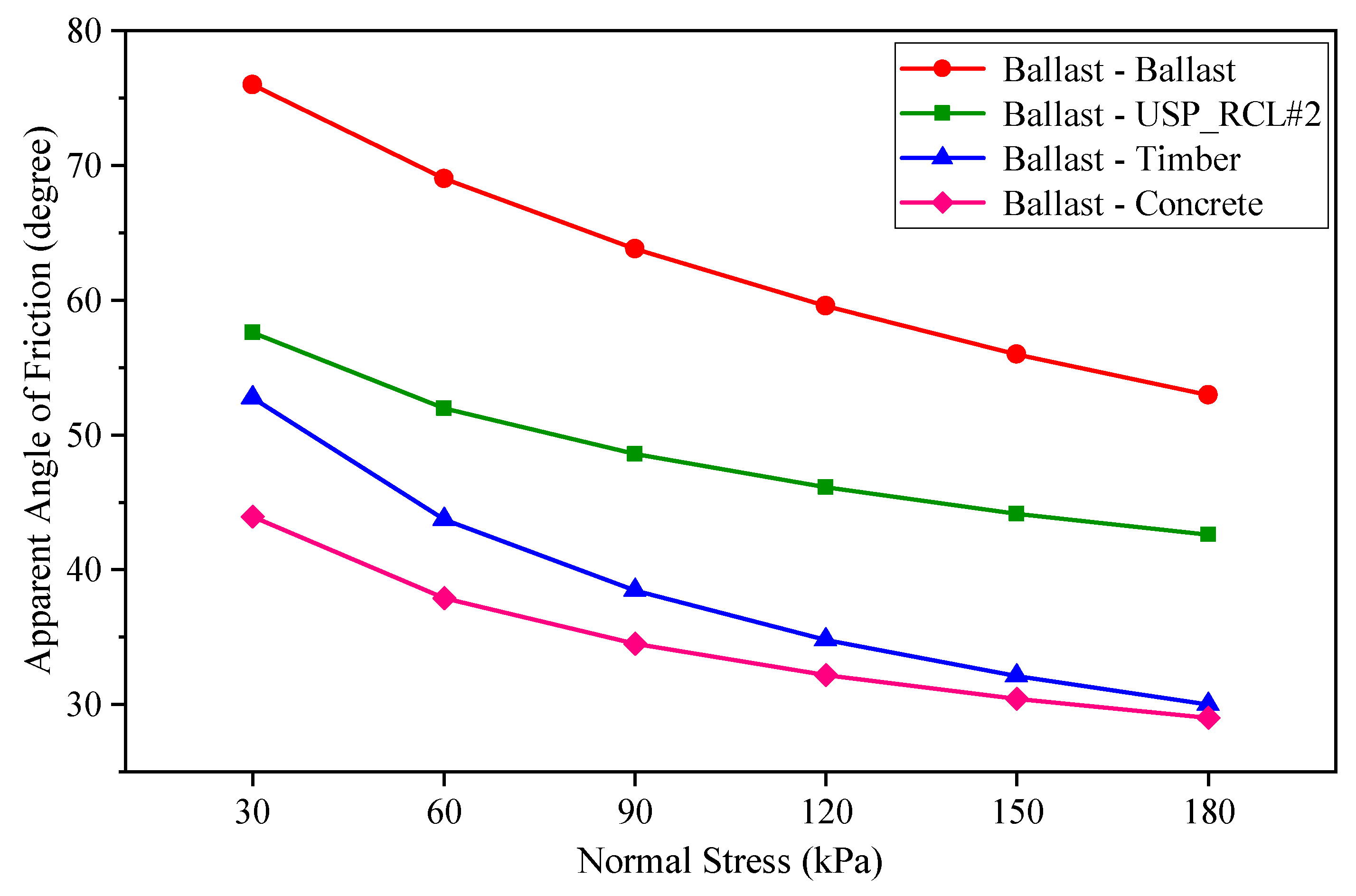
  • The parametric study results of DEM simulation on the shear behaviour of each interface under different normal stresses revealed that when the normal stress increased, the shear stress also increased. For all normal stresses, the ballast–ballast interface showed the highest shear stress variation, followed by the ballast–USP_RCL#2, ballast–timber, and ballast–concrete interfaces, respectively.
  • Based on the DEM results, the non-linear Mohr–Coulomb failure envelopes were developed for each interface. As expected, the ballast–ballast interface had the greatest variation in normalized shear stress, whereas the ballast–concrete interface exhibited the least variation. The apparent friction angle values for each interface were calculated under each normal stress. The friction angle value for ballast–ballast, ballast–USP, ballast–timber, and ballast–concrete interfaces varied between 53° to 76°, 43° to 58°, 30° to 53°, and 29° to 44°, respectively.

Author Contributions

Conceptualization, S.K.N.; methodology, S.K.N. and H.G.S.M.; software, H.G.S.M.; validation, H.G.S.M.; formal analysis, H.G.S.M. and S.V.; investigation, H.G.S.M. and S.V.; writing—original draft preparation, H.G.S.M.; writing—review and editing, S.K.N. and S.V.; visualization, H.G.S.M.; supervision, S.K.N.; project administration, S.K.N.; funding acquisition, S.K.N. All authors have read and agreed to the published version of the manuscript.

Funding

This research was funded by the World Bank through the Accelerating Higher Education Expansion and Development (AHEAD) Operation of the Ministry of Higher Education of Sri Lanka, grant number: AHEAD/RA3/DOR/STEM/No.63.

Institutional Review Board Statement

Not applicable.

Informed Consent Statement

Not applicable.

Data Availability Statement

The data presented in this study are available on request from the corresponding author.

Acknowledgments

The support provided by the District Engineer of the Nanuoya Railway office and the staff of the Gampola Railway Unit of the Department of Railways, Sri Lanka is highly appreciated.

Conflicts of Interest

The authors declare no conflict of interest.

References

  1. Esveld, C. Modern Railway Track; MRT Press: Zaltbommel, The Netherlands, 2001; Volume 385. [Google Scholar]
  2. Li, D.; Hyslip, J.; Sussmann, T.; Chrismer, S. Railway Geotechnics; CRC Press: Boca Raton, FL, USA, 2015. [Google Scholar]
  3. Indraratna, B.; Salim, W.; Rujikiatkamjorn, C. Advanced Rail Geotechnology: Ballasted Track, 1st ed.; CRC Press: Boca Raton, FL, USA, 2011. [Google Scholar]
  4. Navaratnarajah, S.K. Application of Rubber Inclusions to Enhance the Stability of Ballasted Rail Track under Cyclic Loading. Ph.D. Thesis, School of Civil, Mining and Environmental Engineering, University of Wollongong, Wollongong, Austria, 2017. [Google Scholar]
  5. Indraratna, B.; Nimbalkar, S.; Ngo, N.T.; Neville, T. Performance improvement of rail track substructure using artificial inclusions—Experimental and numerical studies. Transp. Geotech. 2016, 8, 69–85. [Google Scholar] [CrossRef] [Green Version]
  6. Sadeghi, J.; Barati, P. Comparisons of the mechanical properties of timber, steel and concrete sleepers. Struct. Infrastruct. Eng. 2012, 8, 1151–1159. [Google Scholar] [CrossRef]
  7. Navaratnarajah, S.K.; Indraratna, B.; Ngo, N.T. Influence of under sleeper pads on ballast behavior under cyclic loading: Experimental and numerical studies. J. Geotech. Geoenviron. 2018, 144, 04018068. [Google Scholar] [CrossRef]
  8. Jayasuriya, C.; Indraratna, B.; Ngo, T.N. Experimental study to examine the role of under sleeper pads for improved performance of ballast under cyclic loading. Transp. Geotech. 2019, 19, 61–73. [Google Scholar] [CrossRef]
  9. Sol-Sanchez, M.; Moreno-Navarro, F.; Rubio-Gámez, M.C. Viability of using end-of-life tire pads as under sleeper pads in railway. Constr. Build. Mater. 2014, 64, 150–156. [Google Scholar] [CrossRef]
  10. Mayuranga, H.G.S.; Navaratnarajah, S.K.; Bandara, C.S.; Jayasinghe, J.A.S.C. Numerical Simulation of Energy-Absorbing Rubber Pads Using FEM and DEM Approaches—A Comparative Study. In ICSECM 2021; Lecture Notes in Civil Engineering; Dissanayake, R., Mendis, P., Weerasekera, K., De Silva, S., Fernando, S., Eds.; Springer: Singapore, 2023; Volume 266, pp. 283–295. [Google Scholar]
  11. Abadi, T.; Le Pen, L.; Zervos, A.; Powrie, W. Measuring the area and number of ballast particle contacts at sleeper/ballast and ballast/subgrade interfaces. Int. J. Railw. Technol. 2015, 4, 45–72. [Google Scholar] [CrossRef]
  12. Stahl, W. Improvement of balasted tracks using sleeper pads—Investigations and experiences in Germany. In Proceedings of the International Conferences on the Bearing Capacity of Roads, Railways and Airfields, Trondheim, Norway, 27–29 June 2005; pp. 1–10. [Google Scholar]
  13. Ngo, N.T. Performance of Geogrids Stabilised Fouled Ballast in RAIL Tracks. Ph.D. Thesis, School of Civil, Mining and Environmental Engineering, University of Wollongong, Wollongong, Austria, 2012. [Google Scholar]
  14. TolouKian, A.R.; Sadeghi, J.; Zakeri, J.-A. Large-scale direct shear tests on sand-contaminated ballast. Proc. Inst. Civ. Eng.-Geotech. Eng. 2018, 171, 451–461. [Google Scholar] [CrossRef]
  15. Gong, H.; Song, W.; Huang, B.; Shu, X.; Han, B.; Wu, H.; Zou, J. Direct shear properties of railway ballast mixed with tire derived aggregates: Experimental and numerical investigations. Constr. Build. Mater. 2019, 200, 465–473. [Google Scholar] [CrossRef]
  16. Estaire, J.; Santana, M. Large direct shear tests performed with fresh ballast. In Railway Ballast Testing and Properties, ASTM STP1605; Stark, T.D., Szecsy, R., Swan, R.H., Eds.; ASTM International: Conshohocken, PA, USA, 2018; pp. 134–151. [Google Scholar]
  17. ISO 20290-1:2021; Aggregates for Concrete—Test methods for mechanical and physical properties—Part1: Determination of Bulk Density, Particle Density, Particle Mass-per-Volume, and Water Absorption. International Organization for Standardization: Geneva, Switzerland, 2021.
  18. IRS-GE-1; Specification for Track Ballast. Research Designs and Standards Organisation (RDSO). Ministry of Railways: Lucknow, India, 2004.
  19. Indraratna, B.; Wijewardena, L.; Balasubramaniam, A. Large-scale triaxial testing of grey wacke rockfill. Geotechnique 1993, 43, 37–51. [Google Scholar] [CrossRef]
  20. Marschi, N.D.; Chan, C.K.; Seed, H.B. Evaluation of properties of rockfill materials. J. Soil Mech. Found. Div. 1972, 98, 95–114. [Google Scholar] [CrossRef]
  21. Olson, R.E.; Lai, J. Direct Shear Testing; Chaoyang University of Technology: Taichung, Taiwan, 1989; pp. 1–14. [Google Scholar]
  22. Wang, X.; Weng, Y.; Wang, X.; Chen, W. Interlocking mechanism of calcareous soil. Rock Soil Mech. 2018, 39, 3113–3120. [Google Scholar]
  23. Wang, X.; Wang, X.-Z.; Zhu, C.-Q.; Meng, Q.-S. Shear tests of interfaces between calcareous sand and steel. Mar. Georesources Geotechnol. 2019, 37, 1095–1104. [Google Scholar] [CrossRef]
  24. Indraratna, B.; Lackenby, J.; Christie, D. Effect of confining pressure on the degradation of ballast under cyclic loading. Geotechnique 2005, 55, 325–328. [Google Scholar] [CrossRef]
  25. Cundall, P.A.; Strack, O.D. A discrete numerical model for granular assemblies. Geotechnique 1979, 29, 47–65. [Google Scholar] [CrossRef]
  26. McDowell, G.; Bolton, M. On the micromechanics of crushable aggregates. Géotechnique 1998, 48, 667–679. [Google Scholar] [CrossRef] [Green Version]
  27. Lu, M.; McDowell, G. Discrete element modelling of ballast abrasion. Géotechnique 2006, 56, 651–655. [Google Scholar] [CrossRef]
  28. Tutumluer, E.; Qian, Y.; Hashash, Y.M.; Ghaboussi, J.; Davis, D.D. Discrete element modelling of ballasted track deformation behaviour. Int. J. Railw. Transp. 2013, 1, 57–73. [Google Scholar] [CrossRef]
  29. Ngo, N.T.; Indraratna, B.; Rujikiatkamjorn, C. DEM simulation of the behaviour of geogrid stabilised ballast fouled with coal. Comput. Geotech. 2014, 55, 224–231. [Google Scholar] [CrossRef] [Green Version]
  30. Ngamkhanong, C.; Feng, B.; Tutumluer, E.; Hashash, Y.M.; Kaewunruen, S. Evaluation of lateral stability of railway tracks due to ballast degradation. Constr. Build. Mater. 2021, 278, 122342. [Google Scholar] [CrossRef]
  31. Ngo, N.T.; Indraratna, B.; Rujikiatkamjorn, C. Micromechanics-based investigation of fouled ballast using large-scale triaxial tests and discrete element modeling. J. Geotech. Geoenviron. 2017, 143, 04016089. [Google Scholar] [CrossRef] [Green Version]
  32. Bian, X.; Li, W.; Qian, Y.; Tutumluer, E. Micromechanical particle interactions in railway ballast through DEM simulations of direct shear tests. Int. J. Geomech. 2019, 19, 04019031. [Google Scholar] [CrossRef]
  33. Danesh, A.; Mirghasemi, A.A.; Palassi, M. Evaluation of particle shape on direct shear mechanical behavior of ballast assembly using discrete element method (DEM). Transp. Geotech. 2020, 23, 100357. [Google Scholar] [CrossRef]
  34. Wang, B.; Martin, U.; Rapp, S. Discrete element modeling of the single-particle crushing test for ballast stones. Comput. Geotech. 2017, 88, 61–73. [Google Scholar] [CrossRef]
  35. Ngo, T.; Indraratna, B. Mitigating ballast degradation with under-sleeper rubber pads: Experimental and numerical perspectives. Comput. Geotech. 2020, 122, 103540. [Google Scholar] [CrossRef]
  36. Indraratna, B.; Ngo, N.T.; Rujikiatkamjorn, C. Performance of ballast influenced by deformation and degradation: Laboratory testing and numerical modeling. Int. J. Geomech. 2020, 20, 04019138. [Google Scholar] [CrossRef] [Green Version]
  37. Cui, X.-H.; Xiao, H.; Ling, X. Analysis of ballast breakage in ballast bed when using under sleeper pads. Geomech. Geoeng. 2022, 17, 677–688. [Google Scholar] [CrossRef]
  38. Xu, Y.; Yu, W.; Qie, L.; Wang, H.; Ning, N. Analysis of influence of ballast shape on abrasion resistance using discrete element method. Constr. Build. Mater. 2021, 273, 121708. [Google Scholar] [CrossRef]
  39. Potyondy, D.O.; Cundall, P. A bonded-particle model for rock. Int. J. Rock Mech. Min. 2004, 41, 1329–1364. [Google Scholar] [CrossRef]
  40. Jayawardena, U.d.S. A study on the engineering properties of Sri Lankan rocks. J. Inst. Eng. Sri Lanka 2001, XXXIV, 7–21. [Google Scholar]
Figure 1. (a) Particle size distribution of ballast with limits of Indian standard gradation [18] and (b) percentages of each sieved size group of ballast.
Sustainability 14 16384 g001
Figure 2. Different sleeper arrangements: (a) timber sleeper; (b) concrete sleeper; (c) concrete sleeper with USP_Raw; (d) concrete sleeper with USP_RCL#1; (e) concrete sleeper with USP_RCL#2.
Sustainability 14 16384 g002
Figure 3. Large-scale direct shear apparatus: (a) photograph; (b) schematic diagram.
Sustainability 14 16384 g003
Figure 4. Different interface test configurations: (a) ballast–ballast; (b) ballast–timber; (c) ballast–concrete; (d) ballast–USP attached to concrete (USP is USP_Raw, USP_RCL#1, or USP_RCL#2).
Sustainability 14 16384 g004
Figure 5. Painted ballast aggregates.
Sustainability 14 16384 g005
Figure 6. Shear area for calculating shear stress (after Olson and Lai [21]).
Sustainability 14 16384 g006
Figure 7. Variation of shear stress against shear strain for all test configurations.
Sustainability 14 16384 g007
Figure 8. Variation of normal strain against shear strain for all test configurations.
Sustainability 14 16384 g008
Figure 9. Ballast breakage index (BBI) and peak shear stress for all test configurations.
Sustainability 14 16384 g009
Figure 10. Breakable ballast particles developed for numerical simulations.
Sustainability 14 16384 g010
Figure 11. Developed DEM models: (a) ballast–ballast interface, (b) ballast–timber interface, (c) ballast–concrete interface, and (d) ballast–USP_RCL#2 interface.
Sustainability 14 16384 g011
Figure 12. Comparison of stress–strain variation of experimental and numerical results for four different interfaces.
Sustainability 14 16384 g012
Figure 13. Variation of shear stress against shear strain under different normal stresses for (a) ballast–ballast, (b) ballast–timber, (c) ballast–concrete, and (d) ballast–USP_RCL#2 interfaces.
Sustainability 14 16384 g013
Figure 14. Non-linear Mohr–Coulomb failure envelopes for each interface.
Sustainability 14 16384 g014
Figure 15. Variation of apparent angle of friction against normal stress for each interface.
Sustainability 14 16384 g015
Table 1. Material properties of different USPs.
PropertyUSP_RawUSP_RCL#1USP_RCL#2
Thickness10 mm10 mm10 mm
Density420 kg/m3920 kg/m3970 kg/m3
Static bedding modulus (DIN 45673-1)0.22 N/mm30.20 N/mm30.19 N/mm3
Young’s modulus6.00 MPa6.12 MPa6.15 MPa
Table 2. Properties of ballast used in DEM simulation.
Property TypeParameterValue
Material propertiesSolid density2950 kg/m3
Shear modulus50 MPa
Poisson’s ratio0.25
Particle-to-particle interaction propertiesCoefficient of restitution0.2
Coefficient of static friction0.5
Coefficient of rolling friction0.01
Bond strength propertiesNormal/shear stiffness per unit area6.84 × 109 N/m3
Normal/shear strength6 MPa
Bond disc scale0.5
Table 3. Properties of different materials used in DEM simulation.
ParameterSteelTimberConcreteUSP_RCL#2
Solid density (kg/m3)78508902400970
Shear modulus (MPa)8.0 × 1043.93 × 1031.5 × 1042.03
Poisson’s ratio0.30.250.20.48
Interfaceballast–steel wallballast–timberballast–concreteballast–USP
Coefficient of restitution0.70.40.60.3
Coefficient of static friction0.70.850.751.5
Coefficient of rolling friction0.050.040.010.08
Table 4. Comparison of numerical and experimental results using mean absolute percentage error (MAPE) and percentage variation in peak shear.
InterfaceMAPE (%)Variation in Peak Shear (%)
Ballast–Ballast (60 kPa)1.61.4
Ballast–Timber (60 kPa)1.05.7
Ballast–Concrete (60 kPa)10.18.5
Ballast–USP_RCL#2 (60 kPa)6.74.4
Ballast–Ballast (30 kPa)9.19.8
Publisher’s Note: MDPI stays neutral with regard to jurisdictional claims in published maps and institutional affiliations.

