
Study on Stope Stability in Continuous Mining of Long-Dip, Thin Orebody by Room–Pillar Method


1
Faculty of Public Safety and Emergency Management, Kunming University of Science and Technology, Kunming 650093, China
2
Faculty of Civil Engineering and Mechanics, Kunming University of Science and Technology, Kunming 650093, China
*
Author to whom correspondence should be addressed.
Sustainability 2022, 14(15), 9601; https://doi.org/10.3390/su14159601
Submission received: 29 June 2022
/
Revised: 22 July 2022
/
Accepted: 1 August 2022
/
Published: 4 August 2022
(This article belongs to the Special Issue Mine Disasters Control and Synergetic Mining: Challenges to Mine Sustainability)
Abstract
:In order to analyze the stability of the stope under continuous mining with the room–pillar method for a kind of orebody with a long inclination, but not deep mining, this paper takes the room–pillar method for the continuous mining of a long-inclination orebody in the Mengnuo Lead–Zinc Mine, Yunnan Province as the research background. On the basis of the analysis of the stope mechanical model of a long, inclined, thin orebody with room-and-pillar mining, based on numerical simulation, the nature of the change in stress, displacement and the plasticity zone of the roof and pillar during continuous mining along the inclination are systematically analyzed. The results show that as the mining depth increases, the roof subsidence of the stope in the middle of the current operation increases. With the continuous mining of the lower middle section, the roof displacement of the stope will continue to increase with the subsequent mining of the middle section until the end of all stope operations, and the roof displacement of the stope has an obvious cumulative effect. The stress on the roofs and pillars increases with the gradual downward movement of the mining in each level, and the distribution of the plastic zone also expands. It shows that the stope structural parameters that are set according to shallow mining cannot fully meet the requirements of stability and safety in mining a deeper orebody. Therefore, for the mining of a non-deep orebody with a greater tendency to extend, the structural parameters of a shallow stope should not simply be used in the mining of a deeper orebody, but the pillar size should be appropriately increased or the spacing between the room and pillar should be reduced to ensure the stability and safety of the continuous stope.
1. Introduction
For underground mines, the stability of the surrounding rock is directly related to the normal production and safety of the mines, and affects the economic benefits of the mines [1,2,3]. The stability of the surrounding rock is not only related to the mechanical properties of the rock mass itself and the mining technical conditions, but also to the change in the mining depth, which is the starting point of researching the similarities and differences between deep mining and shallow mining [4,5]. Whether in shallow or deep mining, the stability of the surrounding rock varies with the change in mining depth. That is to say, even if all of the stopes use the same mining technology and parameter layout, as mining depth increases, the equivalent values of the surrounding rock stress, displacement and plastic zone will show different characteristics and rules, which requires mastering the variation law for the analysis of stope stability. The setting of reasonable parameters for the stope structure is of great significance [6,7].
Many scholars have performed a lot of research on the stope stability of inclined, thin orebody mining. Xu et al., based on Voronoi diagram theory, established an evaluation method for the stability of irregular pillars and analyzed the stability of underground stope groups in the Dayigezhuang Gold Mine. The support countermeasures for controlling the stability of stope groups were put forward [8]. Liu et al., used fracture mechanics and catastrophe theory to analyze the failure law and stability of open-pit pillars. The research showed that when the value of pillar stress intensity ratio is greater than 1, the pillar will lose stability; otherwise, it will not lose stability [9]. Tao et al., used the three-dimensional finite element method to analyze the stability of sublevel caving without a sill pillar under different stope structural parameters. The results showed that large structural parameters can better improve stope ground pressure and enhance stope stability [10]. Sun et al., analyzed the stability of a deep stope based on math and a numerical simulation method and optimized the stope structural parameters [11]. In the mining of steeply inclined orebodies, Chen et al., conducted research based on the actual design case of the mine and proposed a numerical simulation scheme considering the progressive stope wall damage in order to demonstrate the role of the pillars. The results showed that when the pillar is strategically placed in the lower half of the mining plan, the average overbreak can be reduced by 33% [12]. Bazaluk et al., took the Yuzhno-Belozerskyi deposit as an example and studied the deformation process of unstable hanging-wall rock when mining a thick and steep deposit. The results showed that the mining scheme needs to optimize the parameters of pillar, height, width and steep-inclined outcrop to increase the stability of the surrounding rock [13]. Takhanov et al., determined the actual size of the protective pillars and top pillars of the orebody through seismic investigation, and evaluated the possibility of rock-mass collapse and fracture in the lower part of the Zhairemskoye field. In addition, Roclab software was used to refine the physical and mechanical properties of rocks [14]. Garza et al., conducted a reverse analysis on the fracture of a troy pillar in Montana, and prospectively predicted the pillar stability of a nearby Montana deposit according to the analysis results [15]. Guo et al., analyzed the stability of the surrounding rock in the deep continuous mining of a steep-inclined orebody by monitoring, field investigation and other means, and revealed the influence law of the fault on the movement effect of the surrounding rock mass. The stability of a deep-buried carbonaceous phyllite roadway under different support schemes was compared and analyzed by using the large geotechnical engineering analysis software FLAC3D [16,17,18]. From the existing research results, most studies are still focused on the stability of roadways or the surrounding rocks in deep or shallow mining. However, the research results related to the dynamic change in the surrounding rock stability with mining depth are relatively few. Therefore, it is necessary to study whether the stability of the surrounding rock of a stope will change with the continuous increase in mining depth, how the variation law will appear, and whether the stope structural parameters need to be adjusted, in view of the actual situation of a mine being engineered with a larger inclination length. The research results are not only of great significance to safe mining, but also provide a theoretical basis for the rational design of the stope.
2. The Particularity of Mining Long-Dip, Thin Orebody
There is no doubt that the magnitude of in situ stress varies with the burial depth of the long-inclined orebody. To some extent, the stability of the stope surrounding rock is determined by the magnitude of in situ stress, which affects the setting of the stope structural parameters of the long-inclined, thin orebody. For a kind of orebody that is not being deep-mined by definition, the design of the stope structure parameters is carried out according to conventional experience in production [19,20]. However, if the orebody tends to be deep, then the difference in the in situ stress in mining the lower orebody will inevitably lead to the stability of the surrounding rock showing different characteristics from those in the mining of the upper orebody, which has some influence on the safe mining of the mine. Therefore, for the mining of a long-inclined, non-deep orebody, the changing trend of the surrounding rock stability along with the continuous change in mining depth is analyzed, and the adverse impact on safety production and its degree are grasped, so as to provide theoretical guidance and reference for the rational layout of the stope structural parameters.
3. Engineering Situation
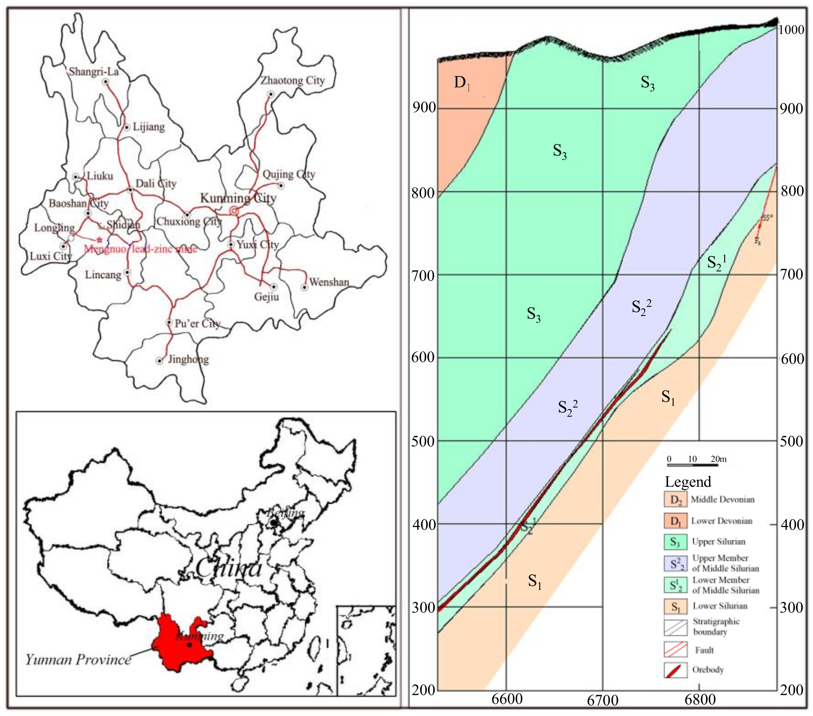
This Mengnuo Lead–Zinc Mine is located in Mengxing Town, Longling County, Baoshan City, Yunnan Province, China. The mining area is located in the east wing of the Mengxing secondary syncline structure, which is nearly north to south. The mining area is mainly divided into the 795 pit and the 860 pit. The outcropped strata in the area are mainly metamorphic rocks of Devonian Middle and Lower Series, Silurian, Ordovician and Cambrian Gongyanghe groups. The lithology mainly includes bedded limestone, crystalline limestone, general phyllite, carbonaceous phyllite, and sandstone. The hanging and footwall of the deposit is lamellar limestone. The average thickness of the orebody in the No. 20 exploration line of the 860 pit is 2.5 m, the dip angle of the orebody is 30–50 degrees, and the height of the middle section is 50 m. It is divided into seven levels. The buried depth of the orebody in level 600 is 386 m and extends 455 m along the dip direction. The surrounding rock of the orebody roof and floor is mainly laminated limestone, which belongs to type III surrounding rock. The surface topography of the mining area fluctuates slightly, and there is little groundwater impact on mining. The main orebody mined in the mining area is lead–zinc ore, which is mined by the room-and-pillar method. The room-and-pillar method is a kind of open-stope mining method, which divides the stage (gently inclined, inclined deposit) or panel (horizontal, slightly inclined deposit) into several rooms and pillars (leaving regular discontinuous pillars). The mining work is carried out in the room. In the stage, the room and the pillar are alternately arranged and the pillar is not recycled under normal circumstances. The geological data of the deposit are obtained from the geological survey report provided by the enterprise. Figure 1 shows the location of the mining area and the engineering geological profile.
4. Stope Mechanical Model of Room-and-Pillar Mining in Long-Dip, Thin Orebody
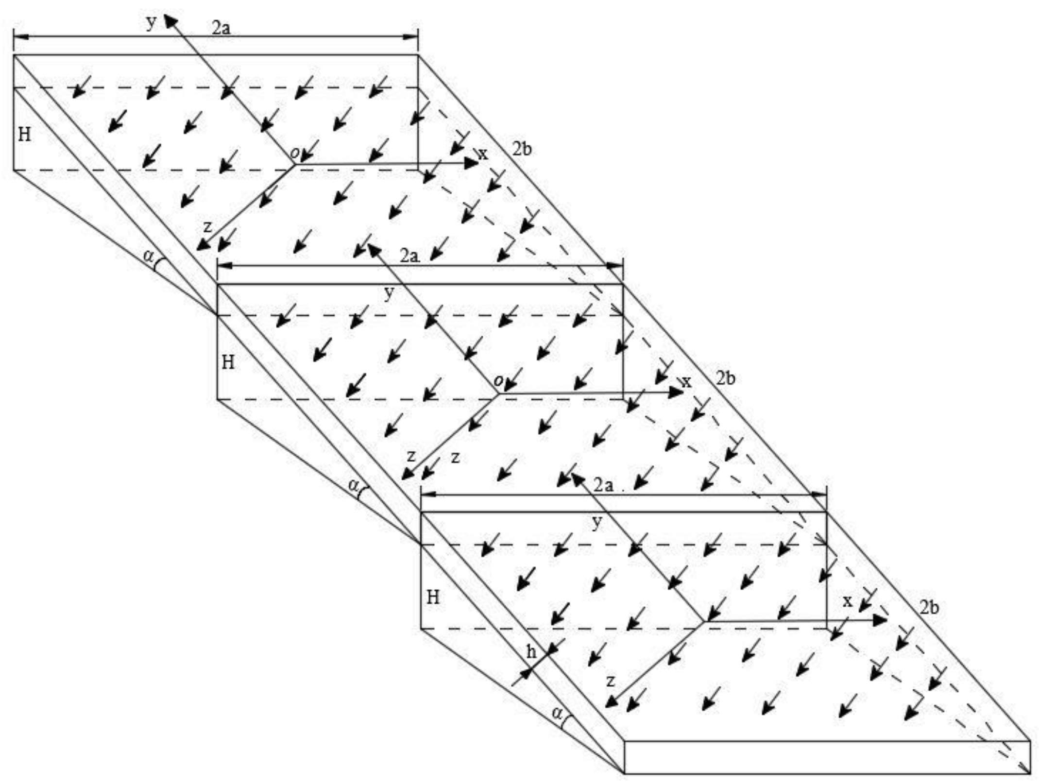
The room-and-pillar method is used to mine a long-inclined, thin orebody from top to bottom, and the goaf is under the stress balance state under the support of the top pillars, bottom pillars and point pillars. At this time, the pillars play a vital role in the process of the surrounding rock stability. Without considering the local failure of the roof, the roof of each middle-section goaf of a long-inclined, thin orebody mined by the room–pillar method is simplified as a set of equivalent elastic, rectangular, thin plates supported by a Burgers body [21,22], as shown in Figure 2. The elastic rectangular plate is assumed to be 2a in length, 2b in width (b ≥ a) and the thickness is h; E is the elastic modulus of the roof rock, is Poisson’s ratio, is the body density, is the tensile strength, α is the dip angle of the orebody, the average area of pillars is S, and the height is L. The total number of pillars in each room is m, n middle sections can be divided along the dip direction, and the height of each middle section is H.
Then, the roof control equation of the first middle section of the long-dip, inclined, thin orebody is as follows:
In the formula, is the curvature of the stope roof; D is the bending stiffness of the stope roof; is the coefficient of uniform surface force, which is equivalent to the pillar supporting force. It is assumed that is the stress on the roof of the first middle stope, the stress on the roof of the Nth middle section stope is , and H is the height of the middle section. The mechanical properties of the ore pillars are represented by a Burgers body [21], as shown in Figure 3.
Assuming that the pillars are equidistant, the total uniform load q acting on the roof is composed of , and the self-heavy load of the roof, that is, the uniform load of the first middle-section roof is , and the uniform load of the Nth middle-section roof is . If the uniform load is regarded as the pressure exerted by the overlying rock mass on the roof surface of the first middle section, then the roof uniform load of the Nth middle-section stope is , and the load of each of the middle-section pillars is treated as an equivalent uniform load.
Based on the results of the rheological tests conducted on the rock mass, a Burgers body can be used to simulate the pillar of a long-dip, thin orebody, as shown in Figure 4, and its constitutive relation is as follows:
where, and are the elastic coefficients of the Burgers model; and are the viscosity coefficients.
Then, the constitutive relation of the stope pillars in a long-dip, thin orebody mined with the room-and-pillar method is as follows:
The axial strain and displacement of the pillars in a goaf are related as follows:
By introducing the Burgers constitutive relation (6) and strain displacement relation (7) into the goaf roof-control Equation (2) of the long-dip, thin orebody, it can be drawn that [22]:
where, and are, respectively, the first derivative and the second derivative of the goaf roof-sinking deflection with respect to the time.
From the above-derived formula, it can be found that: For long-dip, inclined, thin orebody mining, when the stope structural parameters and pillar size remain unchanged, as the buried depth increases, the stress of the stope pillar increases, the greater the pillar strain and displacement, the more serious the deformation failure trend, the higher the stress concentration degree of the stope roof, and the roof subsidence and deformation range gradually increase.
5. Numerical Simulation of Stope Stability of Continuous Mining in Long-Dip, Thin Orebody
5.1. Justification of the Geomechanical Model
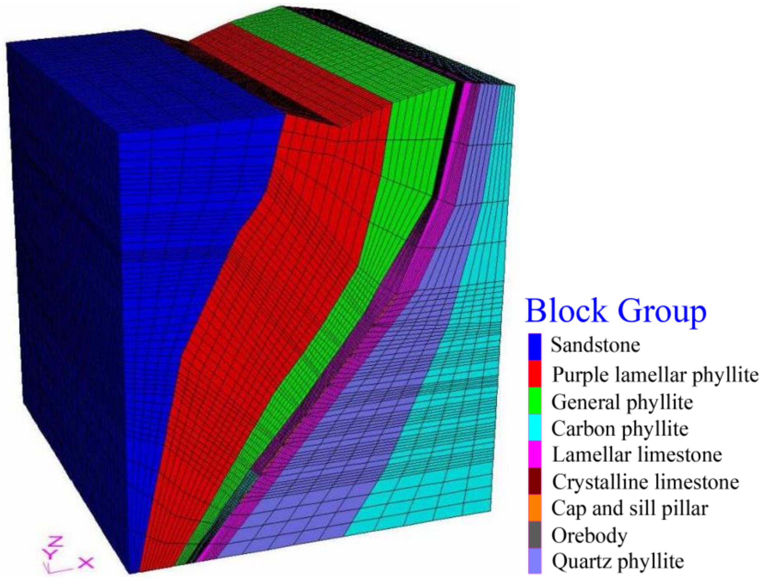
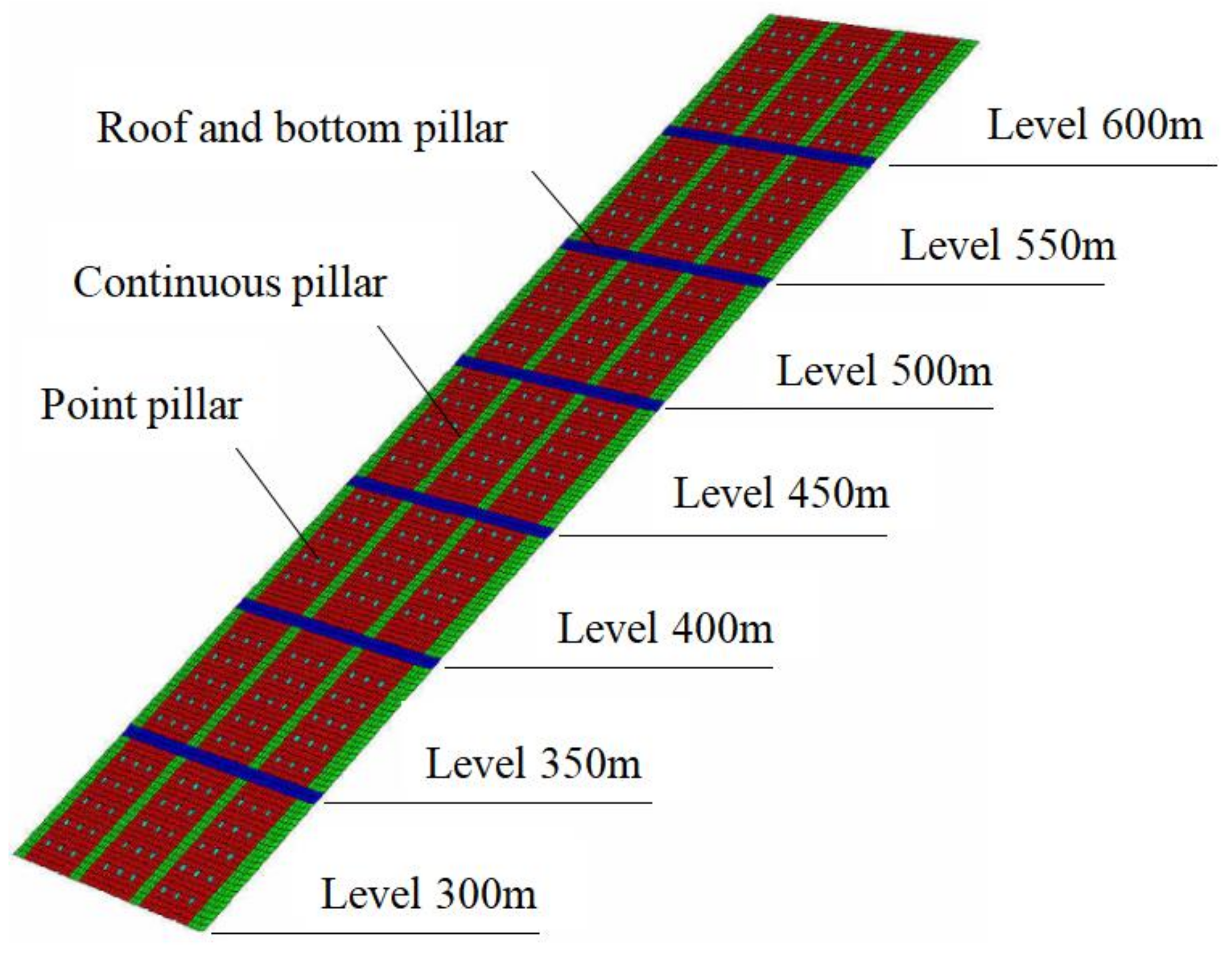
According to the occurrence condition, the actual shape and boundary selection principle of the No. 20 exploration line of the 860 pit, a three-dimensional numerical model is established by FLAC3D [23,24,25]. The length of the model in the X direction is 700 m, the length in the Y direction is 800 m, and the maximum height direction is 1015 m. The angle of the dip of the deposit is 50°. The constraints are fixed by the displacement at the bottom. The in situ stress is mainly gravity stress. The Mohr–Coulomb criterion is used in the constitutive model. There are 250,800 elements and 263,088 nodes in the model. Because this calculation focuses on the analysis of the relationship between the stability of the surrounding rock and the mining depth of the orebody, according to the actual situation, a total of seven middle sections are established from top to bottom, ranging from level 600 m to level 300 m, and each level height is 50 m. The stope structural parameters are set according to the actual parameters adopted in shallow mining, i.e., the length of the stope is 60 m, the size of the pillar is 2 m × 2 m, the spacing of the pillars is 6 m, the width of continuous pillars is 6 m, the width of the top and bottom pillars is 4 m, the width of the stope is 30 m, and three stopes are established in each middle section. The overall calculation model and stope model is shown in Figure 5, the room–pillar model is shown in Figure 6. The physical and mechanical properties of the massif are obtained by the reduction and correction of the physical and mechanical parameters of the rock through the Hoek–Brown strength criterion based on the physical and mechanical parameters of the rock obtained from laboratory tests, and the RMR value of the rock quality evaluation. Table 1 lists the physical and mechanical parameters of each lithology.
5.2. Computational Scheme
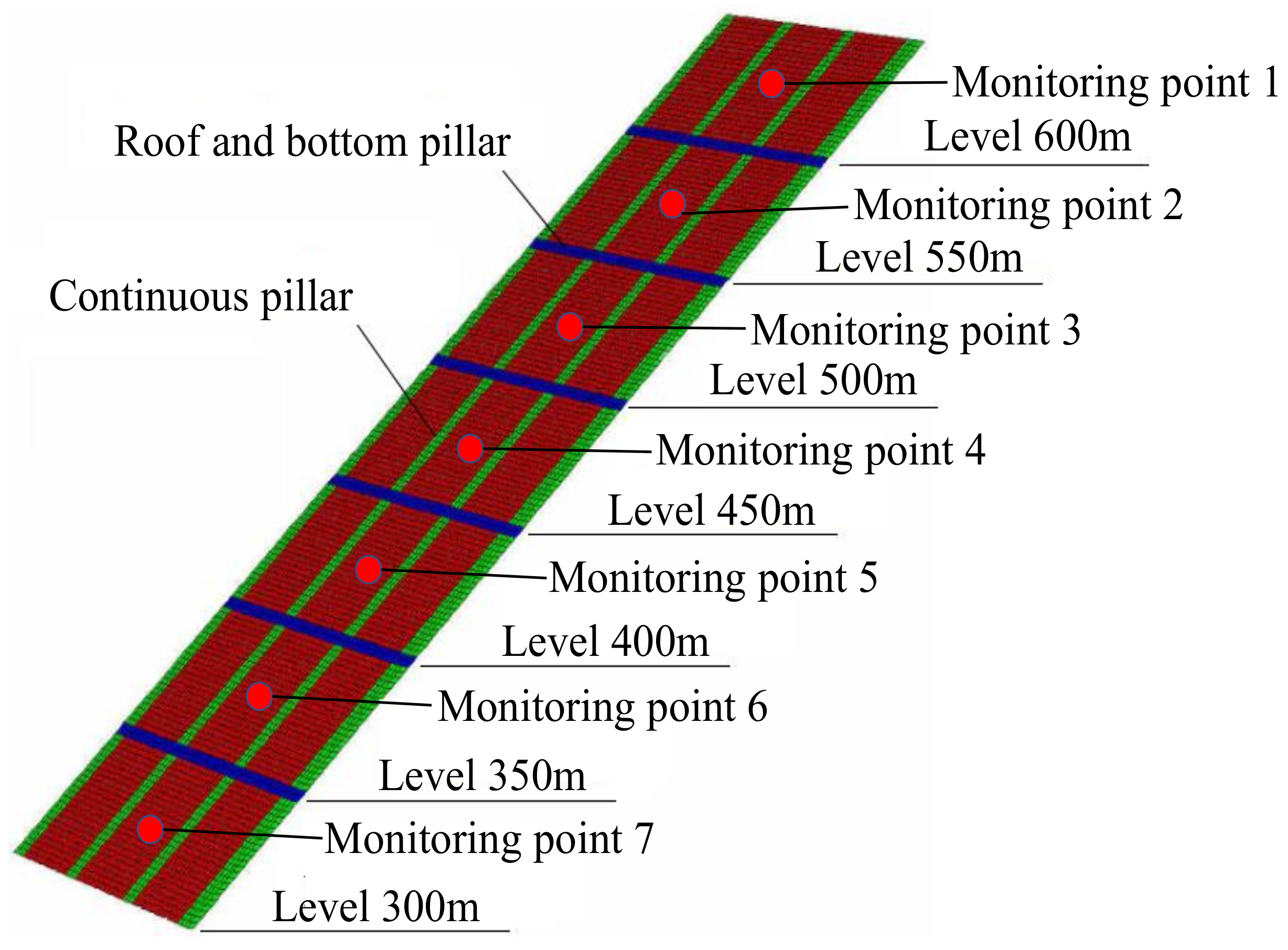
With the gradual downward mining of each middle section and the change in mining depth during mining, the law of deformation and stress of the surrounding rock is analyzed. Seven excavations are carried out in each level, namely level 600, level 550, level 500, level 450, level 400, level 350 and level 300. At the same time, the roof positions of each middle stope have corresponding monitoring points to monitor the displacement change with the decrease in mining depth.
5.3. Analysis of Calculation Results
5.3.1. Stress Analysis
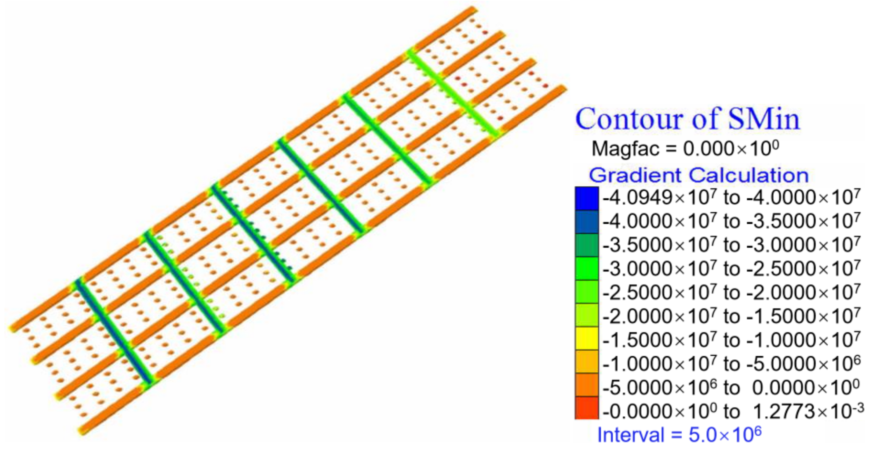
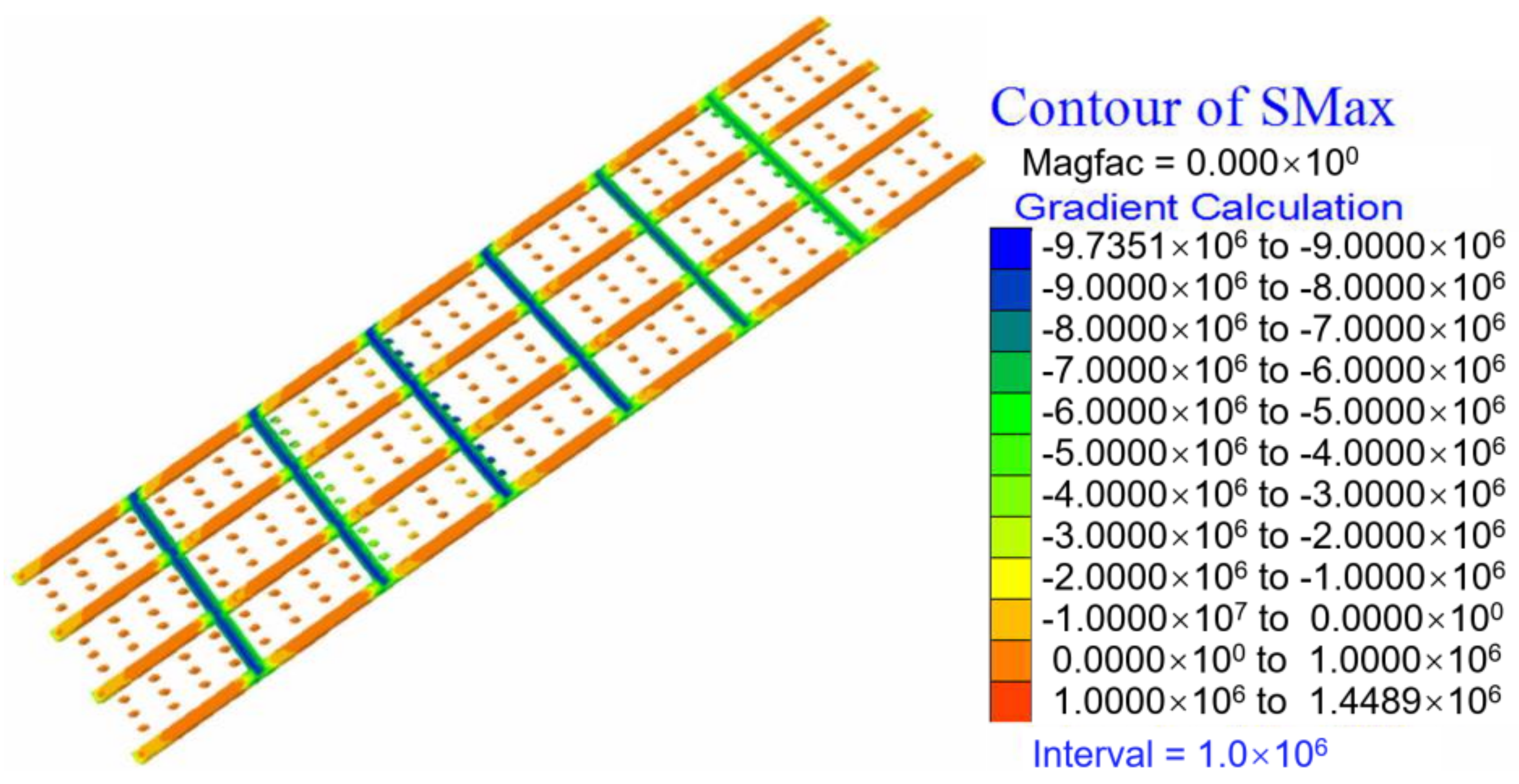
The maximum principal stress and minimum principal stress nephograms of each stope’s pillars, roof and floor are shown in Figure 7 and Figure 8, respectively.
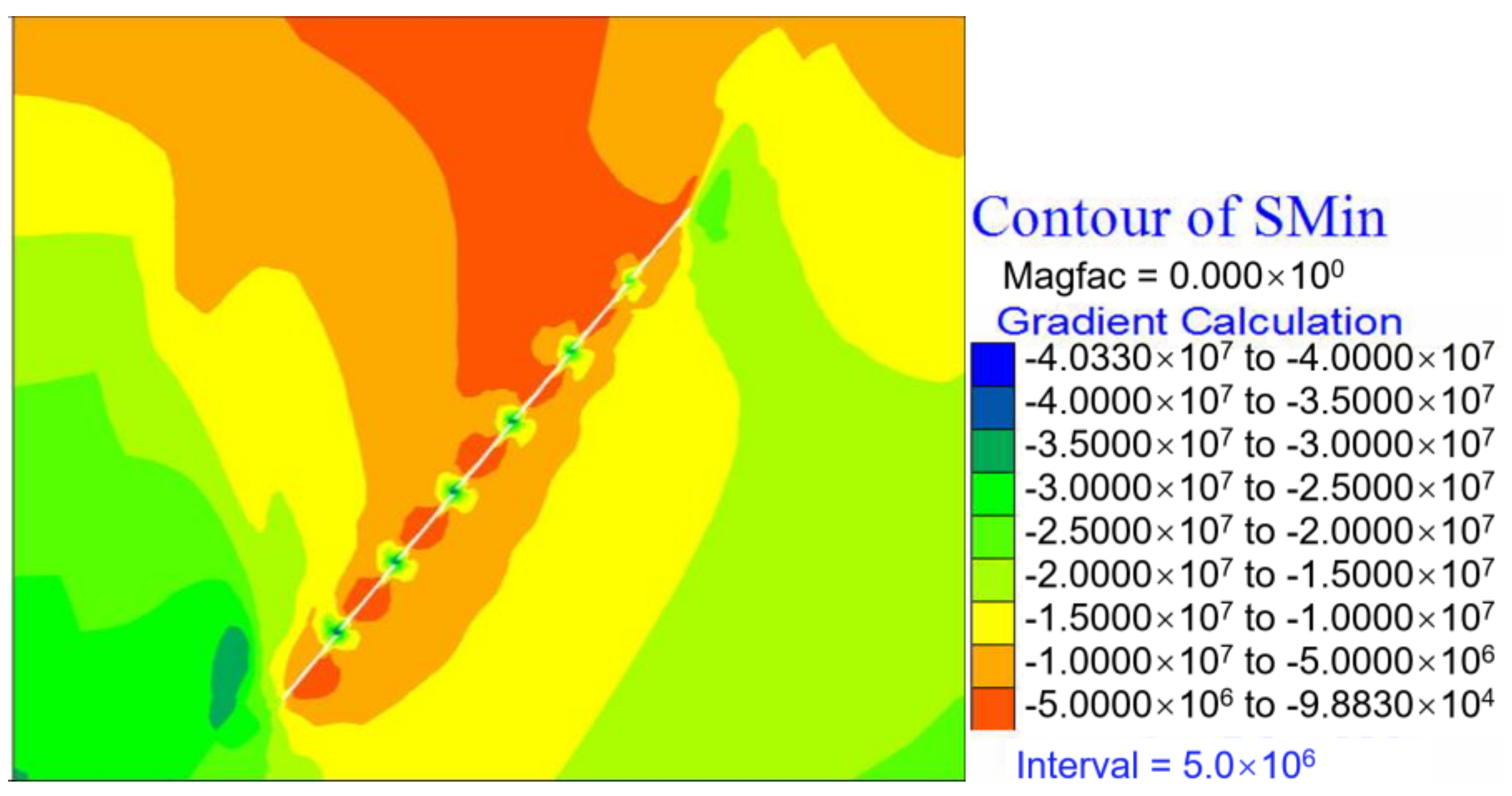
It can be seen that as the mining depth increases, the forces on the pillars also increase, all of which are compressive stress. The maximum principal stress of the top and bottom pillars is larger than that of the continuous pillars and point pillars. The maximum principal compressive stress increases from 15 MPa after level 600 is mined to 40.95 MPa after level 300 is mined, and the maximum tensile stress increases from 0.53 MPa after level 600 is mined to 1.449 MPa after level 300 is mined. The maximum principal stress map in the section direction also shows the same result in Figure 9. When mining to level 450, the stress values of the roof, floor and point pillars of deep stopes gradually begin to increase, and the maximum value reaches 40.33 MPa after level 300 is mined.
As can be seen here, the maximum compressive stress on the pillars reaches 40.95 MPa in the mining of level 300 due to the long mining length in the inclined direction. If the strength of the pillars is low and the structural planes are well developed, then it is easy to induce the first failure of a pillar, which will lead to a series of chain failure reactions of other pillars until reaching overall stope instability. Therefore, under the realistic condition that the mining depth cannot be changed, how to reasonably set the parameters of the pillar layout is the content that needs to be analyzed.
5.3.2. Displacement Analysis
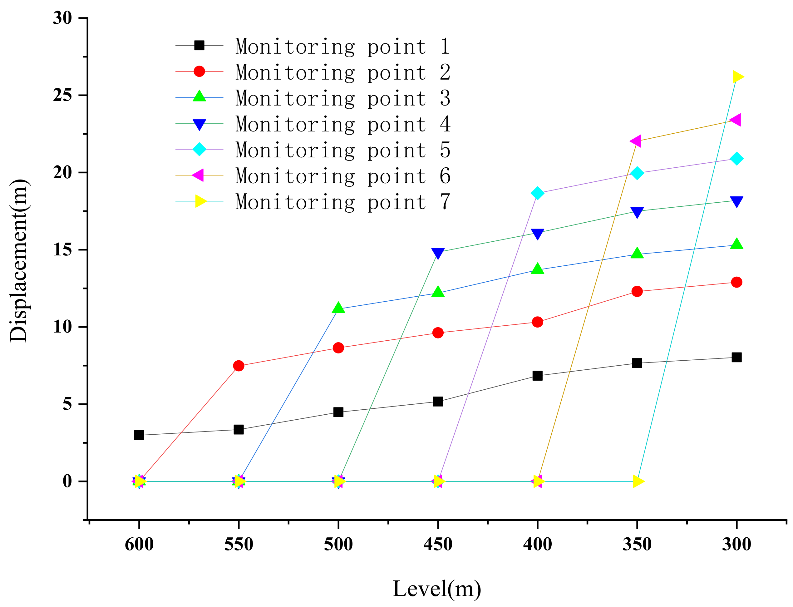
The displacement output of the monitoring point in the middle of the stope roof is arranged in each level, as shown in Figure 10, and the curve with the mining depth is drawn, as shown in Figure 11. It can be seen that the roof displacement of the stope increases with the mining depth, which shows the following rules: (1) When a middle mining section is finished, the current roof displacement of the stope will suddenly increase, and the roof settlement value is positively correlated with the mining depth. That is, the deeper the stope is buried, the larger the roof displacement. For example, the roof subsidence is only 2.99 mm after level 600 is mined, and the maximum subsidence of the roof is 16.1 mm after level 450 is mined, while the displacement of the roof increases to 26.2 mm after level 300 is mined. (2) With the continuous mining, the roof displacement of the previous mining stope will still increase, but the maximum subsidence increase will be smaller and smaller. The above analysis shows that although the working stope ends and moves down, the roof displacement will not stop, but will continue to increase. In addition, the deeper the mining, the greater the roof displacement value, and the stronger the ground pressure appearance. In consequence, if the orebody is buried deep along the inclination, not only do the deformation and stability of the surrounding rock in the deep stope need to be considered, but also the safety of the upper completed goaf, because if the roof lithology is poor or severely cut by the structural plane, then deep-mining activities will also cause the deformation, movement and even destruction of the upper goaf.
5.3.3. Plastic Zone Analysis
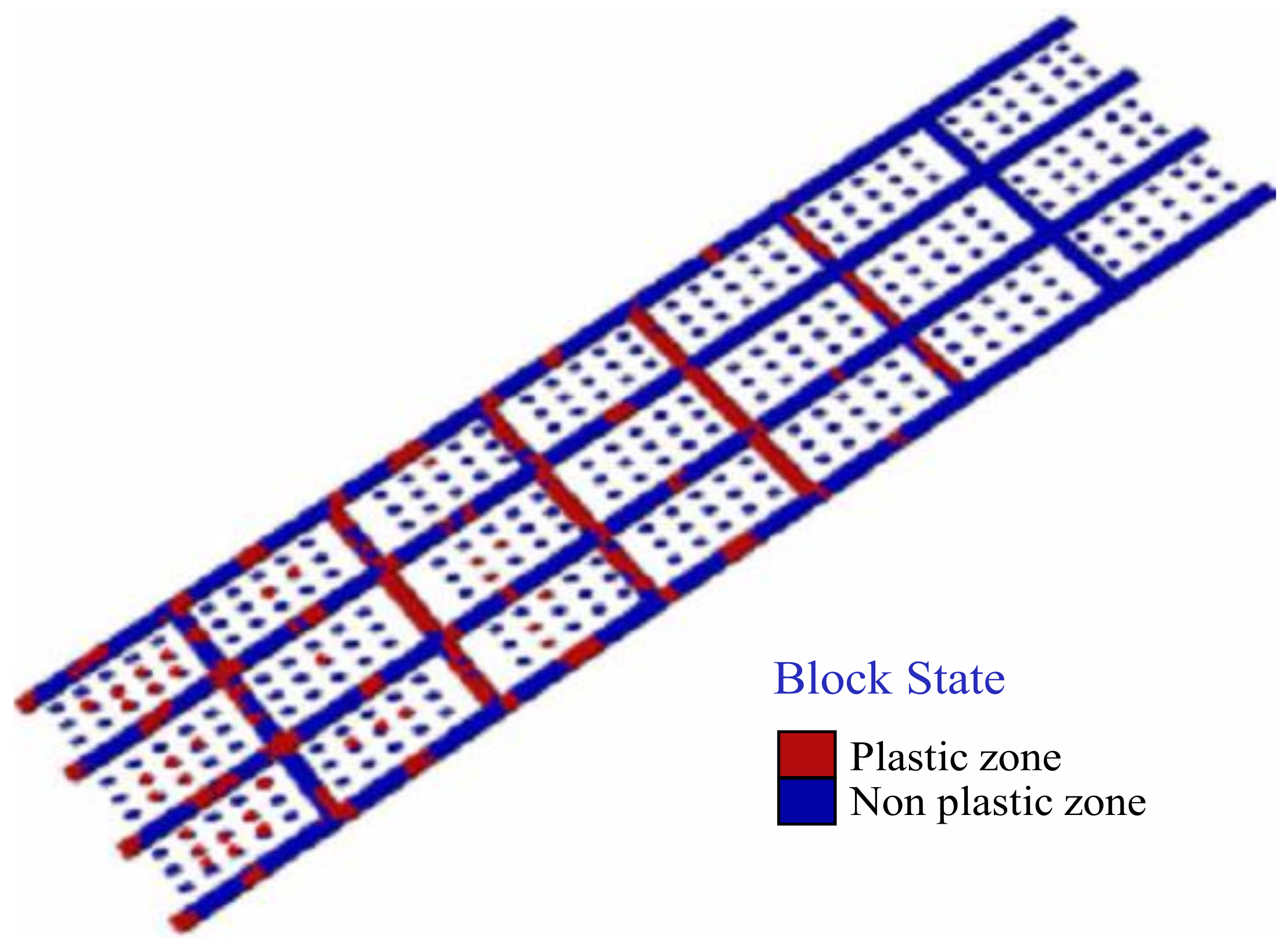
Observing the appearance law of the pillars’ plastic zone and the surrounding rock of the roof and the bottom pillars in the stope, although their spatial distribution is also closely related to mining depth, as shown by the stope stress, the occurrence time and failure mechanism of the plastic zone are different. In the pillars, after mining, the stope is relatively stable after level 600 and level 550 are mined. Plastic areas appear only in the roof and floor pillars of level 550. After mining in level 500 and level 450, some plastic areas also appear in the continuous pillars. When level 400 and level 350 are mined, pressure shear failure occurs in some areas of the point pillars. At this time, the roof and bottom pillars appear to be in the unstable state (Figure 12). The plastic zone of the slab surrounding rock appears much earlier, after mining level 500. As the stope continuously advances, the plastic zone scope becomes wider and wider. The failure mechanism of the rock mass also presents a variety of failure modes from single-compression shear failure to compression shear failure, tension shear failure, and so on.
6. Proposals for Continuous Mining of Long-Dip, Thin Orebody by Room–Pillar Method
From the previous simulation results, it is not difficult to see that although it is not strictly deep mining, the mining technical conditions of the upper and lower orebodies change due to the tendency for large extensions of the orebody, which leads to the different characteristics of the upper and lower stope stability with the same stope structural parameters. That is, with the gradual increase in orebody depth, the roof subsidence of the stope increases. The increase in the stress on the pillars and the extension of the plastic zone ultimately reduce the stability and safety of the whole stope.
Therefore, when arranging the stope structural parameters, it is not appropriate to simply copy the shallow parameters and the existing experience or to unify the production according to a given parameter without considering the change in mining depth. Orebodies with different mining depths should be treated differently. That is, with the gradual increase in mining depth, structural parameters such as pillars and chambers should be correspondingly adjusted, such as appropriately increasing the pillars. In this case, the above parameters should be adjusted in the mining of level 400, in particular the width of the roof and bottom pillars should be appropriately increased, so as to maintain the stability of the stope’s surrounding rock and ensure that the mine can continue to produce efficiently and safely.
7. Conclusions
- (1)
- The Burgers model of rock mechanics is introduced into the mining of a long-inclined, thin orebody, the failure mechanism of the goaf roof of the long-inclined, thin orebody is studied, and the rheological mechanical model of the stope of the long-inclined, thin orebody is established, providing a theoretical foundation for the optimization of the stope design and stope support of this kind of orebody.
- (2)
- In the room–pillar mining of thin orebodies with a greater tendency to extend, the roof displacement of the stope is proportional to the mining depth, that is, the deeper the stope is buried, the larger the roof subsidence. For instance, the roof subsidence is only 2.99 mm, while the displacement of the roof increases to 26.2 mm after level 300 is mined. With the continuation of mining, the roof displacement of the upper stope that has been finished will not stop, but will continue to increase, with the increasing range becoming smaller and smaller.
- (3)
- When the same stope structural parameters are used to extract long-dip orebodies, as mining depth increases, the compressive stress on the pillars and roofs obviously increases. For example, the maximum principal stress increases from 15 MPa to 40.95 MPa, and the maximum tensile stress increases from 0.53 MPa to 1.449 MPa. As the stope continuously advances, the plastic zone scope becomes wider and wider. The failure mechanism of the rock mass also presents a variety of failure modes from single-compression shear failure to compression shear failure, tension shear failure, and so on. This shows that the stability of the stope tends to decline under the existing stope structural parameters.
- (4)
- For long-dip, thin orebodies mined with the room-and-pillar method similar to the Mengnuo Lead–Zinc Mine, although its mining conditions are different from those of pure deep mining, the influence of the continuous variation of mining depth on the stability of the stope should also be noticed. When mining the lower part of the orebody, the existing stope structural parameters should be adjusted appropriately, such as reducing the spacing of the room or pillar, increasing the size of the point pillars, and increasing the width of the room and bottom pillars and the continuous pillars, so as to ensure the long-term stability of the stope surrounding rock.
Author Contributions
Conceptualization, Y.G.; methodology, Y.G.; validation, Y.G. and Y.M.; formal analysis, Y.G. and Y.M.; resources, Y.G.; writing—original draft preparation, Y.G.; writing—review and editing, Y.G. and Y.M.; funding acquisition, Y.G. All authors have read and agreed to the published version of the manuscript.
Funding
This work was supported by the Scientific research fund project of Yunnan Provincial Department of Education, China (no. 2022J0065), Key technology research and pilot test of underground coal gasification, a major scientific and technological research project of CNPC (no. 2019e-25), Key projects of analysis and testing fund of Kunming University of Science and Technology, China (no. 2021T20200145), China Postdoctoral Science Foundation Project (no. 2017M620433), General projects of Yunnan basic research program (no. 2018FB075).
Institutional Review Board Statement
Not applicable.
Informed Consent Statement
Not applicable.
Data Availability Statement
Not applicable.
Conflicts of Interest
The authors declare no conflict of interest.
References
- He, M.C.; Xie, H.P.; Peng, S.P.; Jiang, Y.D. Study on rock mechanics in deep mining engineering. Chin. J. Rock Mech. Eng. 2005, 24, 2803–2813. [Google Scholar]
- Davide, E.; Doug, S. An integrated numerical modeling-discrete fracture network approach applied to the characterization of rock mass strength of naturally fractured pillars. Rock Mech. Rock Eng. 2010, 43, 3–19. [Google Scholar]
- Tesarik, D.; Seymour, J.; Yanske, T. Post-failure behavior of two mine pillars confined with backfill. Int. J. Rock Mech. Min. Sci. 2003, 40, 221–232. [Google Scholar] [CrossRef]
- Swift, G.M.; Reddish, D.J. Stability problems associated with an abandoned ironstone mine. Bulletin Eng. Geol. Environ. 2002, 61, 227–239. [Google Scholar]
- Martin, C.D.; Chander, N.A. The progressive fracture of Lacdu Bonnet granite. Int. J. Rock Mech. Min. 1994, 31, 643–659. [Google Scholar] [CrossRef]
- Dong, J.K.; Feng, X.T.; Zhang, X.W.; Zhang, Z.H. Stability evaluation and param eter optim ization on the fractured rockmass around underground stope. J. Northeast. Univ. 2013, 34, 1322–1326. [Google Scholar]
- Zhang, Q.L.; Cao, X.G.; Wang, Y.L.; Liu, H.Q. Stability analysis of stope roof-pillar based on cusp catastrophe model. China Saf. Sci. J. 2011, 21, 52–57. [Google Scholar]
- Xu, W.B.; Song, W.D.; Cao, S.; Jiang, G.J.; Wu, F. Stopes stability in underground mine and its control technique. J. Min. Saf. Eng. 2015, 32, 658–664. [Google Scholar]
- Liu, H.Q.; Zhang, Q.L.; Pan, C.J.; Kang, Q. Analysis of the failure law and stability of the pillar in open stope mining. J. Min. Saf. Eng. 2011, 28, 138–143. [Google Scholar]
- Tao, G.Q.; Ren, Q.Y.; Luo, H.; Liu, Z.D. Stability analysis of stope in pillarless sublevel caving. Rock Soil Mech. 2011, 32, 3768–3799. [Google Scholar]
- Sun, Y.; Luo, L.M.; Deng, W.H. Stability Analysis and Parameter Optimization of Stope in Deep Metal Mines. Gold Sci. Technol. 2017, 25, 99–105. [Google Scholar]
- Chen, T.; Mitri, H.S. Strategic sill pillar design for reduced hanging wall overbreak in longhole mining. Int. J. Min. Sci. Technol. 2021, 31, 975–982. [Google Scholar] [CrossRef]
- Bazaluk, O.; Petlovanyi, M.; Zubko, S.; Lozynskyi, V.; Sai, K. Instability Assessment of Hanging Wall Rocks during Underground Mining of Iron Ores. Minerals 2021, 11, 858. [Google Scholar] [CrossRef]
- Takhanov, D.; Muratuly, B.; Rashid, Z.; Kydrashov, A. Geomechanics substantiation of pillars development parameters in case of combined mining the contiguous steep ore bodies. Min. Miner. Depos. 2021, 15, 50–58. [Google Scholar] [CrossRef]
- Garza-Cruz, T.; Pierce, M.; Board, M. Effect of Shear Stresses on Pillar Stability: A Back Analysis of the Troy Mine Experience to Predict Pillar Performance at Montanore Mine. Rock Mech. Rock Eng. 2019, 52, 4979–4996. [Google Scholar] [CrossRef]
- Guo, Y.H.; Luo, L.; Xu, H.H.; Zhu, C. Analysis of the Regularity and Mechanism of Fault Activation Caused by Deep Continuous Mining of Shizishan Copper Mine, China. Adv. Mater. Sci. Eng. 2022, 2022, 4027231. [Google Scholar] [CrossRef]
- Guo, Y.; Luo, L. Monitoring and Analysis of Deformation Evolution Law of Fault Activation Caused by Deep Mining in Shizishan Copper Mine, China. Appl. Sci. 2022, 12, 6863. [Google Scholar] [CrossRef]
- Guo, Y.H.; Hou, K.P. Loose Circle Test and Active-passive Combined Support Technology for Deep Buried Carbonaceous Phyllite Tunnel. Chin. J. Undergr. Sp. Eng. 2021, 17, 214–221. [Google Scholar]
- Potyondy, D.O. Simulating stress corrosion with a bonded-particle model for rock. Int. J. Rock Mech. Min. Sci. 2007, 44, 677–691. [Google Scholar] [CrossRef]
- Vyazmensky, A.; Stead, D.; Elmo, D.; Moss, A. Numerical Analysis of Block Caving-Induced Instability in Large Open Pit Slopes: A Finite Element/Discrete Element Approach. Rock Mech. Rock Eng. 2009, 43, 21–39. [Google Scholar] [CrossRef]
- Yu, G.B.; Yang, P.; Chen, Z.C. Study on surrounding rock stability of pillar extraction in thin gently inclined ore body. J. China Coal Soc. 2013, 38, 294–298. [Google Scholar]
- Wang, J.A.; Shang, X.C.; Liu, H.; Hou, Z.Y. Study on fracture mechanism and catastrophic collapse of strong roof strata above the mined area. J. China Coal Soc. 2008, 33, 850–855. [Google Scholar]
- Ghasemi, E.; Ataei, M.; Shahriar, K.; Sereshki, F.; Jlali, S.E.; Ramazanzadeh, A. Assessment of roof fall risk during retreat mining in room and pillar coal mines. Int. J. Rock Mech. Min. 2012, 12, 80–89. [Google Scholar] [CrossRef]
- Singh, G.S.P.; Singh, U.K.; Murthy, V.M.S.R. Application of numerical modeling for strata control in mines. Geotech. Geol. Eng. 2010, 513–524. [Google Scholar] [CrossRef]
- Ghasemi, E.; Shahriar, K. A new coal pillars design method in order to enhance safety of the retreat mining in room and pillar mines. Saf. Sci. 2012, 50, 579–585. [Google Scholar] [CrossRef]
Figure 1.
Mining area location and engineering geological profile.

Figure 2.
Stope mechanical model of long-dip, thin orebody with room-and-pillar mining method.

Figure 3.
Mechanical system of roof and pillar of long-inclined, thin orebody with room-and-pillar method.
Figure 3.
Mechanical system of roof and pillar of long-inclined, thin orebody with room-and-pillar method.

Figure 4.
Mechanical model of Burgers.

Figure 5.
Numerical calculation model.

Figure 6.
Numerical calculation model of room–pillar model.

Figure 7.
Maximum principal stress nephogram of pillars.

Figure 8.
Minimum principal stress nephogram of pillars.

Figure 9.
Maximum principal stress nephogram of stope surrounding rock and pillars.

Figure 10.
Layout of monitoring points in the middle of stope roof.

Figure 11.
Subsidence curves of stope roof subsidence with mining depth.

Figure 12.
Plastic zone of pillars.


Table 1.
Physical and mechanical parameters of rock mass and orebody.
| Lithology | Density (g/cm3) | Uniaxial Tensile Strength (MPa) | Elasticity Modulus (GPa) | Cohesion (MPa) | Friction Angle (°) | Poisson Ratio |
|---|---|---|---|---|---|---|
| Orebody | 4.15 | 1.2494 | 55.1 | 0.7036 | 33.93 | 0.319 |
| Sandstone | 2.71 | 0.8922 | 18.4 | 0.6659 | 49.19 | 0.084 |
| Lamellar limestone | 2.75 | 0.9801 | 21.1 | 0.5242 | 30.43 | 0.103 |
| Crystalline limestone | 2.82 | 0.9314 | 67.5 | 0.5443 | 33.32 | 0.309 |
| Phyllite | 2.64 | 0.5498 | 13.2 | 0.4448 | 32.05 | 0.300 |
Publisher’s Note: MDPI stays neutral with regard to jurisdictional claims in published maps and institutional affiliations. |
© 2022 by the authors. Licensee MDPI, Basel, Switzerland. This article is an open access article distributed under the terms and conditions of the Creative Commons Attribution (CC BY) license (https://creativecommons.org/licenses/by/4.0/).
Share and Cite
MDPI and ACS Style
Guo, Y.; Miao, Y. Study on Stope Stability in Continuous Mining of Long-Dip, Thin Orebody by Room–Pillar Method. Sustainability 2022, 14, 9601. https://doi.org/10.3390/su14159601
AMA Style
Guo Y, Miao Y. Study on Stope Stability in Continuous Mining of Long-Dip, Thin Orebody by Room–Pillar Method. Sustainability. 2022; 14(15):9601. https://doi.org/10.3390/su14159601
Chicago/Turabian StyleGuo, Yanhui, and Yichen Miao. 2022. "Study on Stope Stability in Continuous Mining of Long-Dip, Thin Orebody by Room–Pillar Method" Sustainability 14, no. 15: 9601. https://doi.org/10.3390/su14159601
Note that from the first issue of 2016, this journal uses article numbers instead of page numbers. See further details here.