Review

A Critical Assessment on Functional Attributes and Degradation Mechanism of Membrane Electrode Assembly Components in Direct Methanol Fuel Cells

by
Arunkumar Jayakumar
1,*,
Dinesh Kumar Madheswaran
1 and
Nallapaneni Manoj Kumar
2,*
1
Green Vehicle Technology Research Centre, Department of Automobile Engineering, SRM Institute of Science and Technology, Kattankulathur 603203, India
2
School of Energy and Environment, City University of Hong Kong, Kowloon, Hong Kong
*
Authors to whom correspondence should be addressed.
Sustainability 2021, 13(24), 13938; https://doi.org/10.3390/su132413938
Submission received: 15 November 2021 / Revised: 7 December 2021 / Accepted: 15 December 2021 / Published: 16 December 2021
(This article belongs to the Special Issue Resources Conservation, Recycling and Waste Management)

Abstract

:
Direct methanol fuel cells (DMFC) are typically a subset of polymer electrolyte membrane fuel cells (PEMFC) that possess benefits such as fuel flexibility, reduction in plant balance, and benign operation. Due to their benefits, DMFCs could play a substantial role in the future, specifically in replacing Li-ion batteries for portable and military applications. However, the critical concern with DMFCs is the degradation and inadequate reliability that affect the overall value chain and can potentially impede the commercialization of DMFCs. As a consequence, a reliability assessment can provide more insight into a DMFC component’s attributes. The membrane electrode assembly (MEA) is the integral component of the DMFC stack. A comprehensive understanding of its functional attributes and degradation mechanism plays a significant role in its commercialization. The methanol crossover through the membrane, carbon monoxide poisoning, high anode polarization by methanol oxidation, and operating parameters such as temperature, humidity, and others are significant contributions to MEA degradation. In addition, inadequate reliability of the MEA impacts the failure mechanism of DMFC, resulting in poor efficiency. Consequently, this paper provides a comprehensive assessment of several factors leading to the MEA degradation mechanism in order to develop a holistic understanding.

1. Introduction

Accelerated climate change and environmental degradation are being suffered globally due to the widespread use of fossil fuels [1]. Fuel cells fall under the category of potential reliable energy systems [2], as most of the renewable energy systems suffer due to their intermittent operational nature [3]. Amongst different types of fuel cells, polymer electrolyte membrane fuel cells (PEMFCs) are arguably the fastest-growing and most likely to be used in the near future because of their unique attributes such as high power density, low operating temperature (60–80 °C), quick start-up, and dynamic response [4]. In particular, when compared to redox flow batteries [5] and Li-ion batteries [6], PEMFC is deemed to be a superior candidate considering numerous factors such as capital cost, electrical efficiency, dynamic response, and power density. Incidentally, the widely used fuel for PEM fuel cells is hydrogen, which poses challenges and concerns in terms of storage and safety that subsequently impede its widespread commercialization [7]. Therefore, significant endeavors have been committed to incorporate direct alcohol fuel cells (DAFC), considering its distinctive benefits such as simple operation, capability, high energy density, safe fuel handling and reasonably low environmental impact. Additionally, DAFC was established to tackle the storage crisis of hydrogen as well as to avoid the necessity of a reformer for the conversion of alcohol to hydrogen [8].
DAFC that uses methanol as a fuel is normally referred to as direct methanol fuel cells (DMFC). Methanol is the extensively utilized fuel for DAFC applications and on a volumetric basis, it has 50% higher specific energy density (6.09 kWh kg−1) than liquid hydrogen (3.08 kWh kg−1), and it is simple alcohol, with only one carbon atom, which oxidizes more effectively than other liquid hydrocarbon fuels. In addition, the methanol infrastructure is well established and safer, unlike hydrogen. [9]. Low boiling point (65 °C), high flammability, and ability to flow through the membrane from the anode to the cathode side (i.e., high crossover) are the limitations of using methanol as a fuel for DAFCs, because the chemical oxidation of methanol and the fuel crossover throughout DMFC operation culminates in a reduced power output, which substantially limits the widespread usage of DMFCs. Additionally, the methanol feed is diluted with CO2 and probably nitrogen, which may comprise CO traces that act as a catalyst poison [10]. CO could be removed from fuel feed using water gas shift and oxidation reactors; however, the removal adversely affects the system efficiency and leads to an increase in volume, weight, start-up period, and response to variations in energy demand of the system [9,11]. Ethanol, on the other hand, can be used as an alternative fuel because of its advantages such as higher energy density than methanol, and its relatively low toxicity. Ethanol possesses additional benefits such as lower cross-over rates that have less detrimental impacts on DAFCs performance; however, ethanol has two carbon atoms (C-C) bonded, and this bond is quite complex to break at the lower operating temperatures of DAFCs [12]. Ethylene glycol is an alternative alcohol fuel for DAFCs, which is less toxic, safer in terms of handling, and has high energy density and lower volatility because of its high boiling point (about 198 °C) compared to methanol. Moreover, ethylene glycol has a theoretical energy density of 4.8 Ah mL−1, which is 17% greater than that of methanol, i.e., 4 Ah mL−1, which is particularly noteworthy for portable electronic applications [13]. Although various types of alcohol are employed as fuel for DAFC, the Direct Methanol Fuel Cells (DMFC) exhibit higher performance and lower crossover compared to DEFCs. This is because, when using ethanol as a fuel, there is a rapid decline in cell voltage at higher current densities, due to the rapid anode poisoning [14]. Owing to the aforementioned unique advantages, it is evident why DMFCs are the most widely employed alcohol-based fuel cells.
From the structural configuration, the DMFC comprises an anode/cathode gas diffusion layer (GDL), anode/cathode catalyst layers (CL), and an electrolyte (i.e., a proton conducting membrane), and bipolar plates (BPPs) on either side. Frequently, these components are engineered separately and pressed all together as a single unit at high pressure and temperature. The CL and GDL integrated with the membrane, as a single unit is referred to as membrane electrode assembly (MEA). This DMFCs’ configuration is similar to that of a PEMFC stack. Methanol with water is fed through the flow channels of BPPs on the anode side of the cell through the flow channel of the bipolar plates and oxygen is fed on the cathode side.
The methanol and water react electrochemically and generate protons, electrons, and CO2 at the anode, due to the methanol oxidation at the CL, as given in Equation (1). The membrane (Nafion®) conducts protons to the cathode and impede the electrons since the membrane is ionically conductive. The membrane also aids in CO2 rejection, because insoluble carbonates are produced in alkaline electrolytes. The electrons thus travel through an external circuit, producing electrical energy and recombining with protons on the cathode side with oxygen atoms and producing water, as given in Equation (2). The overall reactant flow and the ion transfer mechanism is depicted in Figure 1 and given in Equation (3) [15,16,17,18].
Anode   reaction :   C H 3 O H + H 2 O C O 2 + 6 H + + 6 e E a n o d e ° 0.046   V
Cathode   reaction :   3 2 O 2 + 6 H + + 6 e 3 H 2 O E c a t h o d e ° = 1.23   V
Overall   reaction :   C H 3 O H + 3 2 O 2 + H 2 O   C O 2 + 3 H 2 O E c e l l = 1.18   V
The most broadly employed membrane for DMFCs is Nafion®, as it demonstrates exceptional proton conductivity, as well as outstanding mechanical and chemical stability. However, Nafion® possess high fuel crossovers throughout the membrane and they are costly, have inadequate device lifespans, owing to the chemical and mechanical degradation. Hence, the potential constraint of the DMFC system is that it deteriorates from destitute anode kinetics, high catalyst loadings, low power density, and high cost [19,20,21]. Thus, DMFC and DEFC belong to the same family with marginally different characteristics.
In general, methanol should oxidize readily when the anode potential exceeds 0.046 V in proportion to the reversible hydrogen electrode (RHE). Correspondingly, when the cathode potential falls under 1.23 V, oxygen should be decreased gradually. In practice, the sluggish electrode kinetics (kinetic losses) drive electrode reactions to vary from their ideal thermodynamic values, resulting in a substantial reduction of the theoretical cell efficiency [22]. For any fuel cells, the performance, a good grade of stability is a vital requirement and subsequently, the degradation mechanisms for DMFC components have a direct influence on the performance of DMFCs [23]. In addition, the operating circumstances and the degradation processes are directly co-related, given that the degradation of active-type DMFC performance during cyclic voltage loading is significantly greater than under continuous voltage or current operation [24]. However, minimal consideration has been committed to studying the degradation mechanism of the membrane electrode assembly of DMFCs. The present paper provides prominence to the general MEA degradation mechanism of the DMFC system. Considering all these aspects, the paper is categorized into the following sections: Section 2 elaborates on the functional attributes of the various DAFC stack components including the membrane, CL, and the GDL. Section 3 expounds on the degradation involved in the MEA. Section 4 exemplifies the degradation mechanism in the DMFC component arranged systematically. Section 5 summarizes the significance of the work along with the critical assessment and limitations.

2. DMFC Functional Components
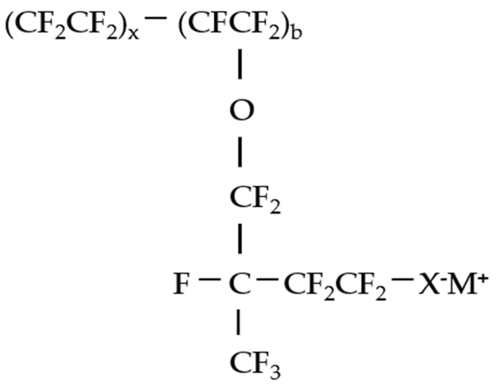
The critical components of the DMFC are the membrane electrode assembly which encompasses the membrane, CL and GDL. To be empathetic on the root causes in the MEA degradation involves the understanding of its functional attributes which are elaborated in the subsequent section.

2.1. Membrane

The membrane acts as a separating layer between the anode and cathode layer, which conducts protons and impedes the flow of electron. The membrane ought to have high proton conductivity, high chemical stability, and must be minimally permeable to methanol and water while possessing high durability at a reasonable cost [25,26]. The membranes for DMFC are normally based on fluorinated polymer and sulfonic acid groups similar to the PEMFC systems [27]. Nafion® is the widely used membrane, which is a perfluorinated polymer, primarily composed of a polytetrafluoroethylene (PTFE) support and lengthy perfluoro vinyl ether pendant side chains that are wrapped up by sulfonic functional groups. The polytetrafluoroethylene (PTFE) support offers chemical and thermal conductivity, while the sulfonated group ensures proton conductivity. The membrane is normally 175 microns in thickness, and the electrodes are typically 2 mm in thickness [28]. Many commercially available membranes are below 175 microns in thickness, but they are not reported to be efficient in proton conduction in the DMFC [29]. The chemical structure of a Nafion® perfluorinated ionomer is given in Figure 2 [30].
The X in the structure of Nafion® predominantly refers to the sulfonic ionic functional groups and the M refers to the metal cation in neutral form of a proton (H+) in the acidic form. Typically, a perfluoro sulfonyl fluoride copolymer-based Nafion® from DuPont, Delaware, USA is observed as the best-fit membrane for DMFCs, due to its high proton conductivity, exceptional mechanical properties, excellent chemical stability, and easy availability. However, it has shortcomings such as high manufacture expense, and at low humidity or high temperatures, these membranes are less proton conductive, have low mechanical property, high alcohol permeability, and are limited to operating temperatures [31]. As a result, such Nafion® membranes are susceptible to rapid dehydration at high temperatures, resulting in loss of proton conductivity, and in certain circumstances, causes irreversible changes in the microstructure of the membrane [32]. As a consequence, the key difficulties in contemporary DMFC research are to produce an alternate membrane capable of operating at higher temperatures or with low humidification of reactants. Choices of Nafion®, on the other hand, are frequently cheaper, i.e., sulfonated polyether ether ketone (sPEEK) membranes [33] and sulfonated poly aryl ethers (SPAEs) [34]. Few commercially available membranes for DMFCs are Aciplex (Asahi Kasei Chemicals, Tokyo, Japan) [35], Flemion (Asahi Glass, Chiba, Japan) [36], Gore-select (W. L. Gore & associates, Newark, DE, USA) [37] and the perfluoro sulfonic acid (PFSA) based Fumapen F-1850 and E-730, (Fumatech Bietigheim-Bissingen, Germany), [38] though Nafion from Dupont is the most prevalent.

2.2. Gas Diffusion Electrode (GDE)

The GDL and the electrode (catalyst) as a single unit is referred to as gas diffusion electrode (GDE) [39]. The GDE for DMFC is typically made of a porous mixture of carbon-backed platinum (Pt) or Ruthenium (Ru) [40]. Pt is predominantly used as the electrocatalyst for DMFC. However, with methanol as a fuel, there could be “CO poisoning.” Therefore, Ru is added to promote the electrocatalyst activity by adsorption of OH and stripping off adsorbed CO from nearby Pt sites. Thus, at the anode, the catalyst, namely, Pt/Ru, in appropriate proportion initiates the methanol electro-oxidation to generate protons and electrons [41]. For an effective electrochemical reaction, the catalyst particles should be in close proximity with the protonic and electronic conductors. Additionally, there should be sections for reactants (i.e., porosity) to reach the catalyst zone and for reaction products to leave the cell [42]. The contact point of reactants, catalyst, and the electrolyte is usually indicated as the three-phase interface [43]. To accomplish an adequate rate of reaction, the area of catalyst zones must be several times greater than the geometrical area of the catalyst. Consequently, the catalysts are made porous to form a three-dimensional network, where the three-phase interfaces are established [44]. The catalysts are typically 0.45 mm thick (before hot-pressing), with a catalyst loading that lies within the range of 0.2 to 0.5 mg/cm2. The catalyst loading is one of the cost-hindering aspects of the DMFC, compared to other MEA components, given that Pt-Ru/C anode catalyst constitutes 36% and Pt/C cathode catalyst constitute 21% of the overall cost of a single DMFC stack in mass production (10,000 units per year), while the membrane and GDL const 12% and 8%, respectively [45]. The DMFC stack cost could not be downsized unless the amount of Pt is reduced by any cost-effective element combined with it, or by entirely replacing Pt with any non-noble elements. Alternative catalysts can be investigated in addition to lessening the CO contamination, thereby reducing the overall cost of the DMFC [46]. Though in certain circumstances, the catalysts are coated onto the membrane, as in the present context, it is taken into the account the CL and GDL as the gas diffusion electrode. The precious catalyst is typically Pt, which has the highest activity towards oxygen reduction reaction (ORR) compared to all catalysts grounded on the Sabatier principle. This systematic configuration is termed as volcano plot and is illustrated in Figure 3 [47].
The GDL in general comprises a macroporous backing layer, usually made of porous, conductive carbon cloth or carbon cloth, and a microporous layer (MPL) [48]. Good diffusion characteristics (facilitating reactants to come in contact with the catalyst site); good electrical conductivity; stability in the DMFC environment; high permeability/pore size distribution for liquids and gases; good elasticity under compression; contact angle of the pores are the favorable features of GDE [49]. The most widely available carbon cloth-based GDL are ELAT [50], Avcarb [51] and CeTech [52], where carbon paper-based GDL are Avcarb [53], Toray [54], Freudenberg [55], Sigracet [56] and Spectracarb [57]. Carbon cloth has an ordered arrangement of fibers, larger pores, high porosity, and permeability, resulting in reduced mass transportation resistance and accelerating effective CO2 removal [58]. Carbon paper, on the other hand, has a packed high denser structure and could be utilized to improve back diffusion of water by retaining a hydraulic pressure at the cathode [59]. A study on structural multiplicity and acclimatization dependence of DMFC reported that, using carbon cloth as the anode GDL and carbon paper as cathode GDL for a DMFC outperformed all other configurations [60]. Metal foams, metal meshes, and sintered metals are used as alternative GDLs in DMFCs [61,62]. Studies reported that the metal foam-enhanced passive DMFC performed better in terms of oxygen transportation and consequently cell performance [63].

3. MEA Degradation and Mitigation Strategies in DMFC

The MEA has often been termed the heart of DMFC. An insight into the degradation mechanism of the MEA can apparently increase the reliability of the DMFC stack. As a consequence, an assessment of the degradation in the membrane and gas diffusion electrode of a DMFC stack is mandatory. A comprehensive and systematic review is a promising way of representing such degradation, as those events can be classified as the primary, secondary, and tertiary consequences which cause the degradation of the stack components. This article logically assesses the combinations of the undesired events that can potentially lead to the undesired state based on numerous research articles reported. The primary consequences are those unsought or most intricate causes, the secondary consequence is the intermediate cause, and the tertiary consequences are at the bottom. In the present work, an assessment is performed on those degradation mechanisms that can lead to the failure of MEA components of DMFC. Nevertheless, similar assessments have been already performed by several researchers that largely focus on hydrogen-based PEMFCs [64,65,66,67]. Though the degradation of DMFC is similar to hydrogen-based PEMFCs, there are significant alterations that have to be assessed. The following sections elaborate on the degradation mechanism in the MEA components of DMFC.

3.1. Electrolyte Membrane

The primary constituent of the membrane degradation is the methanol crossover, followed by various other constituents such as CO poisoning, membrane thickness, methanol concentration, and its impurities, membrane assembly defects, reaction parameters, thermal and mechanical stability, and radical (OH*/HOO*/ROO*).

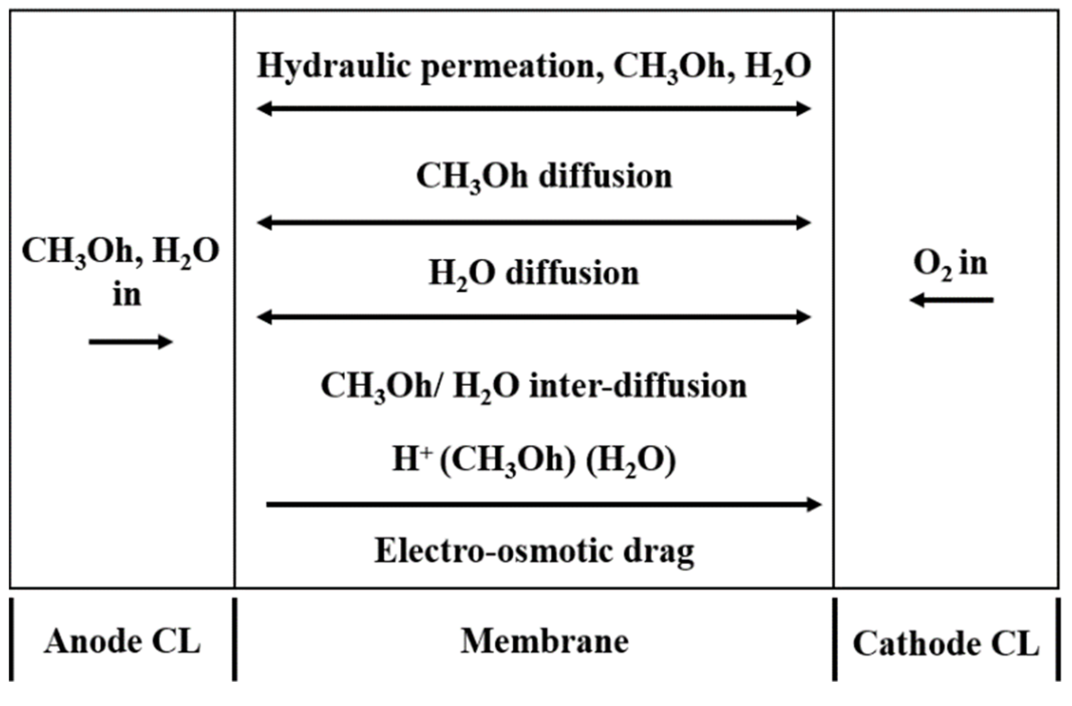
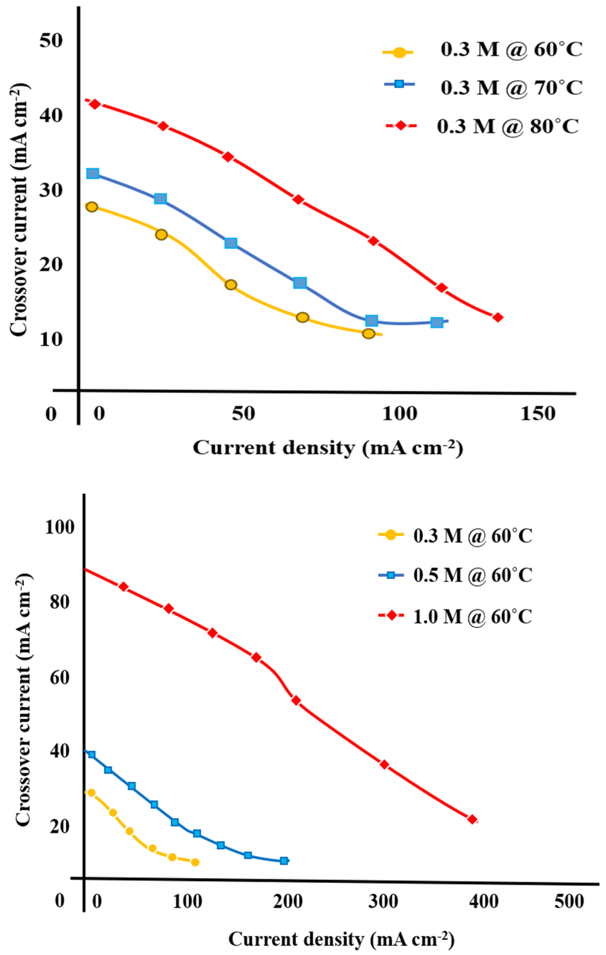
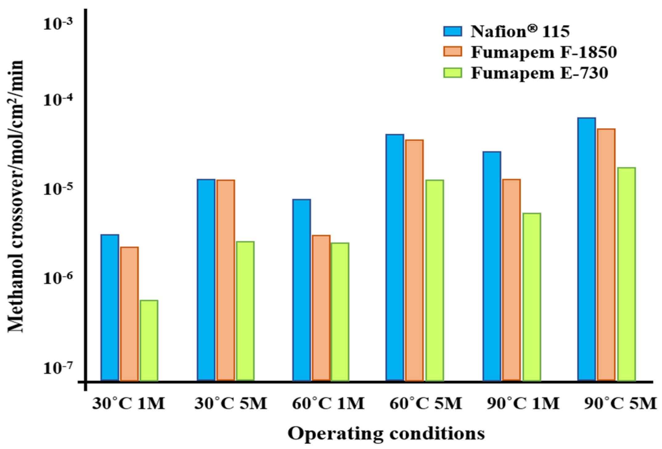
3.1.1. Methanol Crossover

In a liquid-fed DMFC, methanol in excess is provided to the anode of the MEA. It is desired to have all or for most of the methanol diffuse into the anode for the reaction. A phenomenon follows called “methanol crossover (MCO)” where a certain amount of the methanol diffuses over the membrane from the anode to the cathode [68]. The MCO in general is defined using Fick’s law for diffusion across a polymer membrane as given in Equation (4) [69] and its schematic representation is given in Figure 4 [70].
J = D d C d Z
where J is the methanol flux, D is the coefficient of diffusion, C is the methanol concentration and Z is the location within the membrane.
The Inherent water diffusion characteristic of the membrane and methanol solubility in water triggers MCO [71]. Consequently, merely a few elements of methanol oxidize at the anode layer, where the rest of the elements are diffused through the membrane resulting in MCO [72]. This transportation is primarily by the diffusion and electro-osmotic drag (EOD) mechanism [73]. The mass transportation diffusion mechanism is fundamental during MCO, and it is proportional to methanol feed concentration. EOD is generated when proton transfer drags several methanol molecules. The EOD contribution is proportional in MCO., i.e., it increases with increase in amount of methanol fraction at the membrane-electrode (anode) interface and the current generated by the cell [71].
The MCO occurs mostly owing to the nature of the Nafion membrane, as Nafion is made up of hydrophilic side chains that comprise ionic sulfonic acid (−SO3H) groups, which clustered in conjunction to produce ionic channels. While the water flow through ionic channels aids in the transport of protons, allowing for superior proton conductivity, it allows for the passage of methanol across the membrane. This aliphatic polymer structure of Nafion facilitates the development of larger ionic channels, resulting in enhanced methanol permeability [72].
Studies reported that the MCO mostly relies on the operating temperature [74,75,76] and the method of delivering the fuel [77]. It is given that the rate of fuel/oxidant delivered, and their concentration will substantially impact MCO [78]. The linear dependency of current density on temperature and methanol concentration was reported in numerous studies [79,80,81,82,83]. Figure 5 [84] represents cell current density versus methanol crossover current density as a function of temperature and methanol concentration, respectively. While the precise co-relation between permeability and MCO is complicated, certain variables such as the thickness of membrane [85] and methanol feed concentration [86] impact crossover in definite directions, i.e., for greater methanol concentration or thinner membrane, the crossover rates are higher [87]. In addition to permeability, the co-efficient of diffusion and solubility properties are often reported [88]. It is essential to measure these concepts and connect them to the MCO fluxes of operational DMFCs at this phase. This MCO leads to lower theoretical open-circuit voltage (OCV) of ~0.7 to 0.8 V vs. ~1.2 V and low power density of DMFC [89]. MCO produces a mixed potential at the cathode, and consequently decreases the methanol consumption in the anode, thereby decreasing the voltage of the DMFC around 400 mV [90].
The most amount of the MCO to the cathode will be electrochemically oxidized. This leads to the decrease in the performance of the cell and is subjected to the consumption of the cathode reactants [91]. In prevailing liquid feed DMFC, dilute methanol (6.41% to 9.61 vol% CH3OH or 2 to 3 mol) is provided to the anode side of MEA. In such instances, the methanol diffuses to the anode and reacts incompletely.
The residual methanol leaves the CL and thus diffuses through the membrane to the cathode. The deficit of fuel decreases efficiency, which consequently reduces the cathode performance. The methanol loss at the anode side initiates the concentration at the surface of the catalyst to deterioration in the vicinity of the membrane accelerates the mass transportation resistance [92,93].
The hydrophilic properties of Nafion are enhanced by the concentration of hydrophilic domains and as a result, DMFCs elements are easily transported over perfluoro sulfonic acid membranes (mostly water and methanol). This consequently influences MCO from the anode to the cathode, which is primarily accomplished by the diffusion via the water-filled channels inside the Nafion structure and active transportation with protons and associated water solvent molecules during EOD [94]. A rigid polymer matrix [95] and a small free-volume membrane [96] could potentially bring down the electro-osmosis methanol diffusion. At the cathode, the MCO is oxidized to CO2 and H2O, lowering fuel efficiency and leading to cathode depolarization [97]. It is postulated that MCO reduces the efficiency of DMFC by 35%. Although the loss of oxygen from the cathode to the anode has an adverse effect on the efficiency of DMFC, it may be overlooked in contrast to the impact of the MCO. On contrary, mass transfer of N and CO through the membrane has no substantial effect on DMFC performance [95].
It is evident from studies that the MCO is a significant factor that leads to the degradation of the membrane component. From the findings of various experiments reported, higher methanol concentration and substantial membrane thinning was detected, because the Nafion is soluble in methanol. This results in increased MCO and intense mixed potential formation on the cathode. Thus, the incompetence of the membrane to function as an efficient alcohol barrier decreases the performance of the cell as a result of mixed potential at the cathode [98,99,100,101]. Figure 6 [102] illustrates a graph comparing methanol crossover rates at OCV condition and in the presence of 1 and 5 M methanol concentration for some of the tested membranes including the commercial Nafion® 115. This measurement was performed by employing an online gas chromatograph to analyze the CO2 at the cathode. In the sequences E-730, F-1850, and Nafion®-115, the crossover increased.
Numerous studies have examined DMFC performance utilizing anion exchange membranes (AEMs) rather than the more typical proton-based Nafion membrane, with the vast majority reporting higher Ohmic resistance and lower MCO [103,104,105]. While AEM-DMFCs have a greater OCV and marginally improved initial performance compared to Nafion-based DMFCs, the resilience of such membranes often degrades in contrast to Nafion-based membranes, culminating in quick performance degradation [106,107,108]. The quaternized polyaromatics-based AEM polymers such as quaternized polyether ketone and quaternized polysulfone have recently received considerable attention, because of their outstanding conductivity properties, good mechanical and chemical stability [109,110]. However, synthesis of quaternized polyaromatics embraces hazardous compounds such as chloromethylation of benzene rings, which are highly carcinogenic and cytotoxic. Furthermore, the cost for tailoring polymers of quaternized polyaromatics is relatively expensive, which stands as the primary impediment to widespread commercialization [111,112]. Table 1 [113] provides the snapshot of electrochemical characteristics of different membranes used for DMFC.
Various studies have been conducted to control MCO [114,115]. The methanol concentration gradient through the Nafion membrane has high impacts over MCO; however, this approach is said to increase flooding and result in lower energy density [116]. Given that, the methanol tolerant catalysts cannot directly control the MCO rate, though it is capable of reducing the detrimental consequences of it [117,118,119].

3.1.2. Stack Assembly Effects

At high operating temperatures, the membrane degradation rate accelerates owing to the development of pinholes in the membrane in conjunction with cathode degradation and delamination [120]. If any flaw or pinhole appears on the membrane, the reactants blend under the catalytic effect that forms reaction intermediates such as CO, resulting in the hot-spot formation and, in turn, the pinhole dimensions or structural deformation [121]. In extreme circumstances, this could contribute to the explosion of cells, or structural flaws are caused by the following reasons: (i) When the membrane is stabbed by fibers or particles in the MEA during manufacturing and processor during stack assembly [122]; (ii) When the membrane is stabbed or lacerated by MEA or bipolar plate edges under stress produced by the stack bolts [123]; (iii) During long-term operation of the stack, peroxide corrosion makes the membrane thinner, and which leads to pinhole formation, that are more likely to be appeared in membrane drying cases [124]. Despite the above-mentioned reasons, membrane pinhole development can occur under extremely transient circumstances with a high number of humidity cycles. Because of the substantial volumetric expansion of ionomeric membranes under high humidity and in the presence of liquid water, variations in RH cause high mechanical stresses in the membrane, which contribute to membrane pinholes through in the lack of chemical degradation [122]. However, the pinhole formation triggered by short-term mechanical damage or steady long-term corrosion is not known as their effects on performance are not apparent; hence, it is imperative to develop approaches for perceiving membrane pinholes formation to circumvent the potential hazard of explosion or constant performance reduction, and subsequently the reduction in lifespan.
Studies have shown that stresses developed within the system could damage the membrane. These developed stresses are said to have various origins. The first is the initial stresses that arises within the MEA during stack assembly [125]. Numerous studies on optimizing the assembly procedure (such as bolt assembly), especially for the homogenization of the arising mechanical stresses have been reported [126]. A study on the mechanical response of membrane subjected to various clamping conditions observed the formation of pinhole at the center of the membrane which is due to the extreme form of non-uniformity in this constraint configuration [127]. One study observed that clamping stress is conducive to the durability and integrity of the membrane that, however, depends on the design specifications [128]. Evaluating various stack compression methods by considering the vibration effects in the clamping systems of the stack can offer better perceptions of optimal stack assembly procedure. Supplementary efforts are yet to be established to deliver models that combine the physical and electrochemical process concerning assembling and structural issues viz. stress, displacement (deformation), damage (cracks, delamination).

3.1.3. Thermal/Mechanical Stability

In general, Nafion membrane is volatile on operating the stack at temperatures range of above 100 °C. Better cell performance of the cell for Nafion-based membranes is achievable with the operating temperature range of 25 °C to 90 °C. Over 90 °C, the current density is limited as temperature increased, because of the membrane degradation [129]. In recent times, significant attention has been paid to Polybenzimidazole (PBI)-based membranes because of their high thermal stability, which is attributed to their tolerance when operating at higher temperatures (i.e., >100 °C) than Nafion membranes. To achieve maximum power output, it is desirable to increase the operating temperature; PBI membranes are able to endure while operating at temperatures in excess of 100 °C with a vaporized feed [130].

3.1.4. Methanol Concentration and Impurities

The other factors leading to the damage of the membranes are the impurities present in the methanol. DMFCs utilizing various types of commercial methanol con numerous compositions of impurities. The water content in the humidified methane encompasses cationic impurities namely Na+, Cl and Mg2+, that possibly contaminates the membrane surface [131]. The proton loss is more acute with low-valent cations, which is due to the decreased affinity of the sulfonic acid groups present in the Nafion membrane [132]. It was reported that that the MEA substantially degraded with an increase in the corrosion of austenitic stainless steel by the supply of various metal solution concentrations into the fuel stream of DMFC [133]. In addition to impurities with the methanol, the concentration of the fuel adversely affects the MEA performances. Optimum methanol concentration fall in the range of 1–2 M, which entails water dilution and subsequently far lower energy density. The higher alcohol concentration worsens the influence of permeated fuel on the performance of the membrane due to the MCO effect [134]. A study stated that the membrane becomes highly porous and the degree of membrane swelling is increased when there is an increase in alcohol concentration [135]. In general, the pure polar solvent has a greater membrane absorption than the pure non-polar solvent. When water is blended with a solvent, fortunately, the degree of swelling is negatively proportionate to the polarity of the solvent [136].

3.1.5. Membrane Thickness

Membrane thickness in a DMFC influences water crossover as well as water management, which thereby causes membrane degradation. A study reported that when the passive DMFC is worked with low methanol concentration and with a thicker membrane shows better performance at low current densities than at high current densities [137]. The thinnest sPEEK membrane was proven to have good DMFC performance, though also showing low Faradays efficiency (i.e., high methanol permeation with low Ohmic losses). On the other hand, the thickest membrane showed superior qualities concerning methanol permeation [138].

3.1.6. Reactive Oxygen Species

The formation of reactive oxygen species, such as the hydroxyl radical (OH), and hydroperoxyl/peroxyl radicals (HOO/ROO) can also cause the degradation of the membrane. Given that, the Nafion membranes are prone to the high absorption of reactive oxygen species, which leads to a high swelling ratio rate of membranes and fail to properly hold the contact between membrane and catalyst [139]. In the case of the PFSA membrane, the formation of reactive oxygen species also opens up the path for methanol permeability, which leads to high MCO [140].

3.1.7. Mitigation Strategies for Membrane Degradation

The contemporary reliance on Nafion membrane use for DMFC is significant due to its high conductivity and mechanical and chemical stability. The degradation of Nafion membranes, on the other hand, represents a considerable drawback. Hence, exploring an alternate membrane or increasing the performance of the Nafion is critical. Numerous literature has been reported to address the membrane degradation issue. Concerning the methanol crossover reduction, it can be accomplished by utilizing cross-linking procedures or adding up nanosized inorganic fillers within the membrane to improve the tortuosity path, as well as by fine-tuning the ion exchange capacity (IEC) [141]. The alternative approach contemplates the change of the chemical characteristics of the polymer network adjoining the ionic groups to modify the degree of dissociation and the degree of interpenetrated networks [142,143]. These approaches can reduce the level of methanol permeation permeability while keeping the proton conductivity at suitable levels; however, apparently, the cathode is less polarized in the presence of lower methanol permeation [144]. This corresponds to lower overpotentials for the oxygen reduction reaction. This strategy is further assisted by using methanol-tolerant cathode electro-catalysts with high activity for oxygen reduction [145]. FuMA-Tech created a new class of fluorinated membranes for use in DMFCs [146], which exhibited ion exchange capacities of 0.4 and 0.5 meq g−1, that is nominally equated to equivalent weights of 1800 and 2300 g mol−1, respectively. These results differed greatly from those of conventional PFSA membranes, such as Nafion® 115, with an equivalent weight of 1100 g mol−1 and an IEC of 0.91 meq g−1. These blend membranes were designed to restrict methanol crossing, while the cast membrane thickness of 30–50 m enabled minimizing the membrane area resistance and cost of material as contrasted to Nafion® 115, which has a thickness of 125 m.
A relationship (reciprocal of the product of the area-specific resistance and the crossover) between DMFC power density and membrane selectivity is reported in a study [102]. This equation could be used to estimate DMFC performance based on fundamental membrane parameters in the presence of identical catalyst-loading, mechanical, and interfacial features. As explained above, selectivity is connected to intrinsic membrane features. Consequently, determining membrane selectivity does not always necessitate testing in DMFCs. Conductivity, thickness, and methanol permeation properties may all be used to calculate selectivity. If the electrode parameters are known, membrane selectivity can provide an indicator of DMFC performance at low temperatures, according to our research.
Using reinforced composite membrane is another strategy to improve membrane durability in DMFCs. The membrane with silane grafted on graphene oxide-treated mordenite with graphene oxide shows improved durability than conventional Nafion [147]. A thin Nafion membrane comprised of highly surface-functionalized sulfonated silica-coated polyvinylidene fluoride (S-SiO2@PVDF) nanofiber mat and methanol-resistant chitosan. The proposed membrane showed three times greater wet tensile strength (25.2 MPa) and 1.6 times greater elongation (83.5%) than those of the pure Nafion membrane. More vitally, the improved ionic conductivity, reduced methanol permeability, and extremely limited swelling were attained for the composite membrane. These results show that the production of such a mechanically robust membrane with improved proton conductivity, and methanol resistance is a great structural design system. Likewise, in theory, decreasing the molecular weight or increasing the content of silane coupling agent coating could help enhance the conductivity of nanofibers. Similar studies were reported using quaternized chitosan reinforced with surface-functionalized PVDF electrospun nanofibers [148], Polyvinyl alcohol (PVA) reinforced composite membranes [149], poly(styrene sulfonic acid)-grafted poly(vinylidene fluoride) reinforced composites [150], Graphene quantum dot reinforced hyperbranched polyamide membrane [151], to improve the DMFC membrane durability.

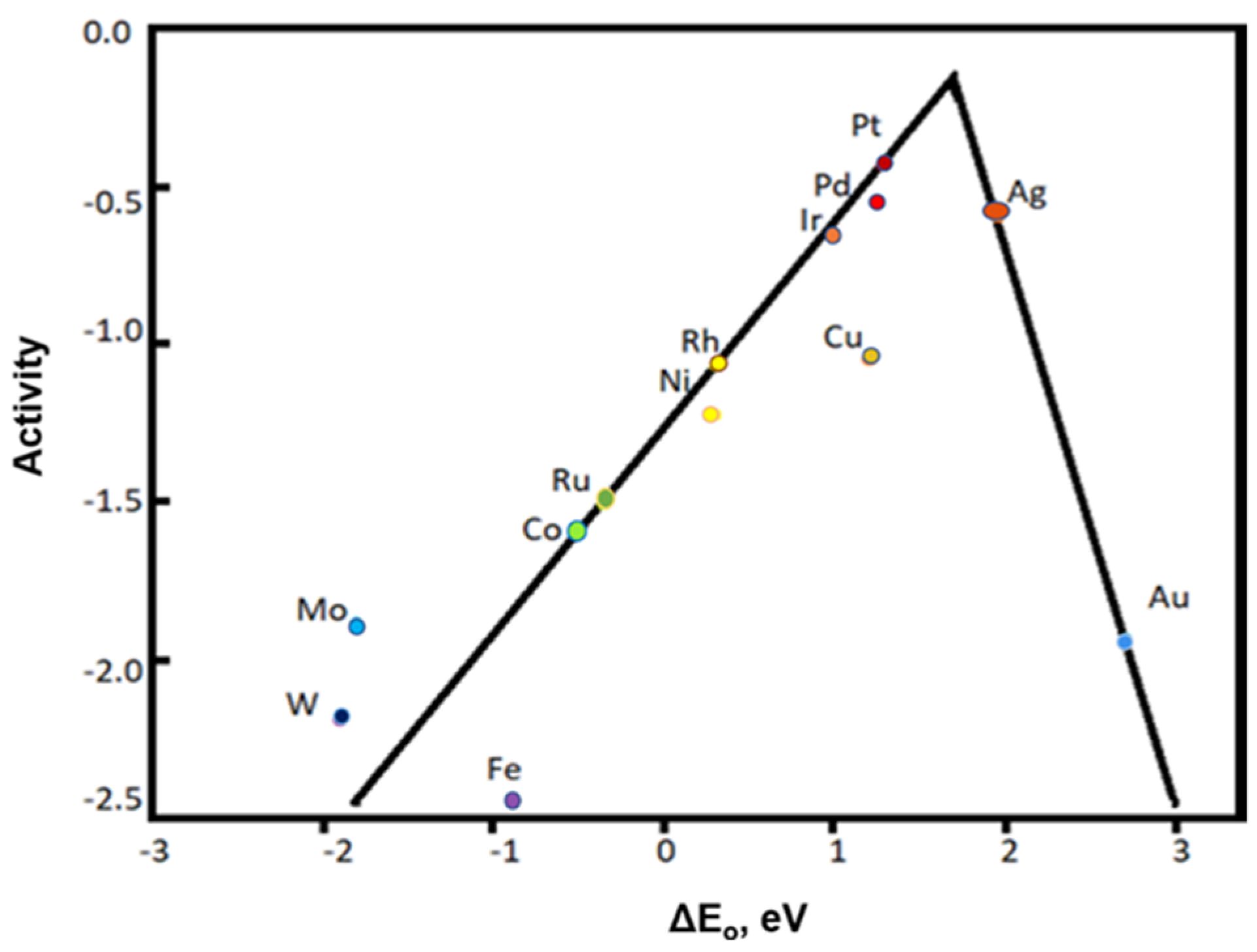
3.2. Electrocatalyst Degradation

The DMFC widespread hindrance is highly influenced by the degradation of the catalyst layer which is accelerated by the following reasons: Catalyst poisoning; Pt/Ru agglomeration; Pt/Ru delamination; Pt/Ru dissolution; Ru leaching from Pt/Ru surface; Surface oxide formation and the membrane dissolution.

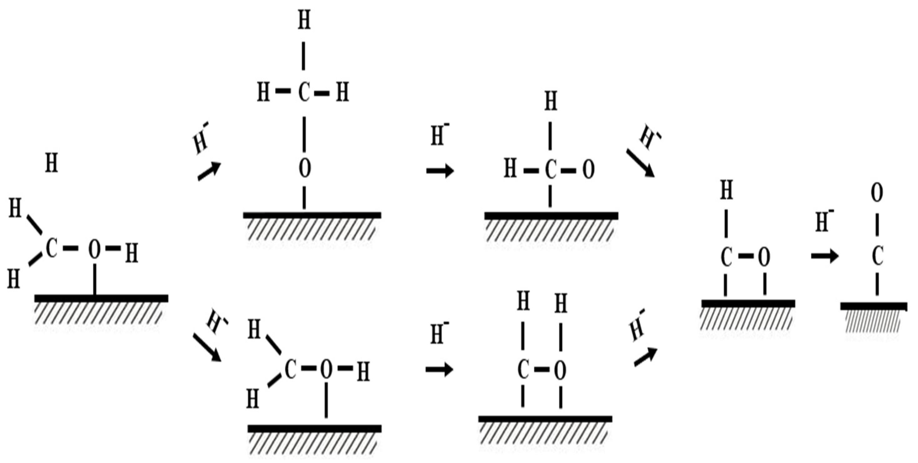
3.2.1. Catalytic Poisoning

CO poisoning, the most severe catalyst deactivation proc, is a critical concern, particularly in direct methanol fuel cells (DMFCs). Figure 7 [152] schematically illustrates the CO formation on the surface of the Pt catalyst.
The intermediates of methanol electro-oxidation impede alcohol oxidation and absorb CO molecules on the electrocatalyst surface which then leads to poisoning the electrocatalyst and hinders the electro-oxidation kinetics [153]. This consequence lead to the use of alloys. Ruthenium as a potentially promising circumvent the CO poisoning [154]. In addition, transition metal carbides have benefits in terms of poison resistance; for instance, tungsten carbide (WC) has unique character traits such as high electrical conductivity, acid resistance, relatively low cost, and resistance to CO poisoning during methanol electro-oxidation [155].

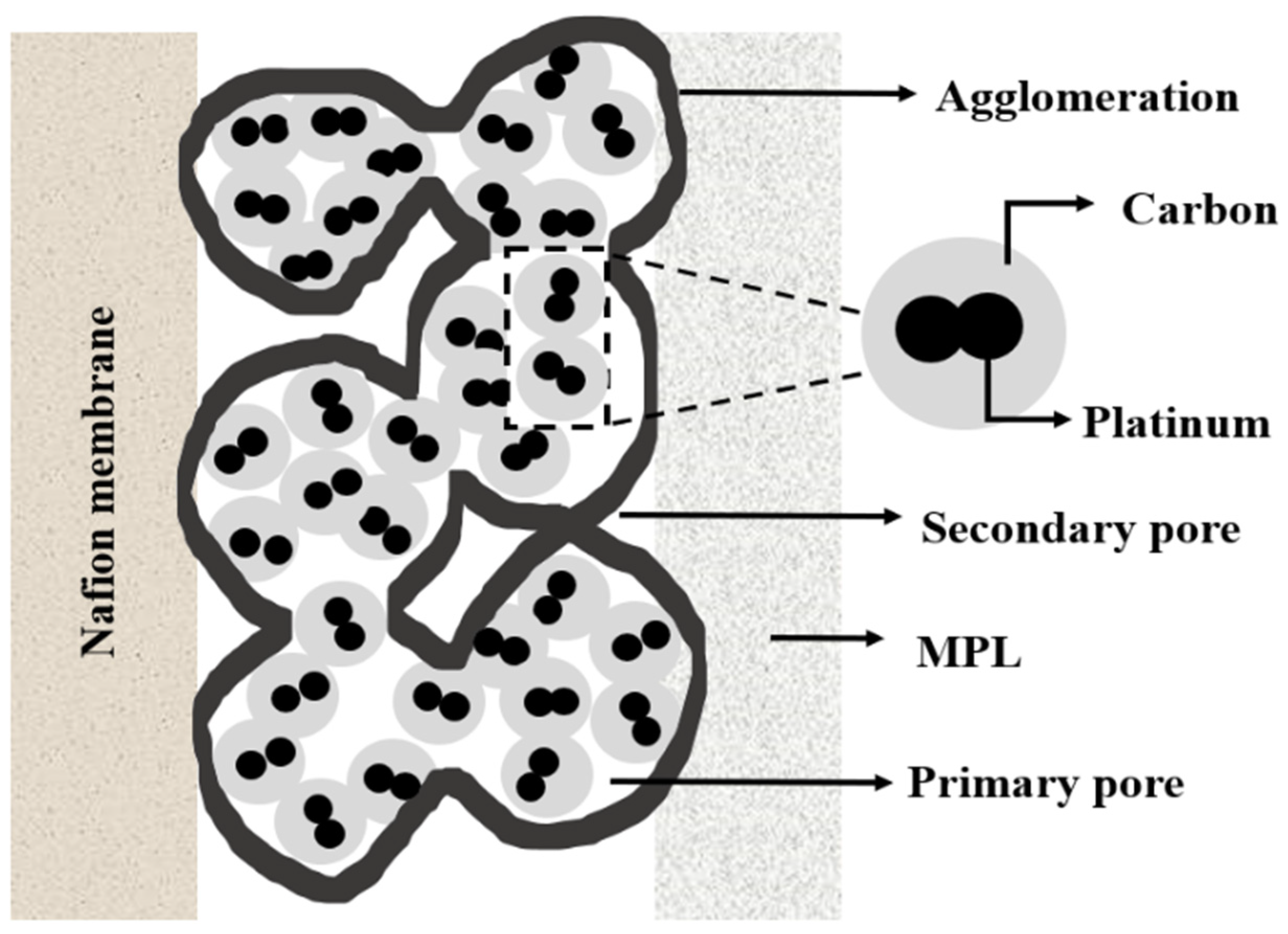
3.2.2. Pt/Ru Agglomeration

The overall growth in particle size during methanol oxidation is described by agglomeration. The mechanism varies on the particles’ distance and support characteristics. Given that the specific particles are in the nearby vicinity or linked to each other, thus producing the larger sized group, the catalyst material diffused and increase together throughout potential cycling. This further formed as a layer with the membrane and MPL on either side and degrades on constant operation [156]. The mechanism of Pt agglomeration at the cathode side of DMFC is given in Figure 8 [157]. Constant advancements in catalyst ink development have been attained such as decreasing the Pt/Ru loading and substituting Pt-black with Pt-supported carbon black [144]. The carbon support typically comprises several carbon black particles, namely, Vulcan (20 µm) or Ketjen black (50 µm). When the particles turn out to be coupled together by fusion bonding in the ink solution, then the aggregates produce agglomerates by attractive van der Waals forces [158].
In a study, aggregates of various forms were modelled as particle clusters and distributed randomly in space to develop an agglomerate composition of the catalyst layer. It was observed that when aggregates overlapped, a new spot of agglomeration was randomly formed [159].

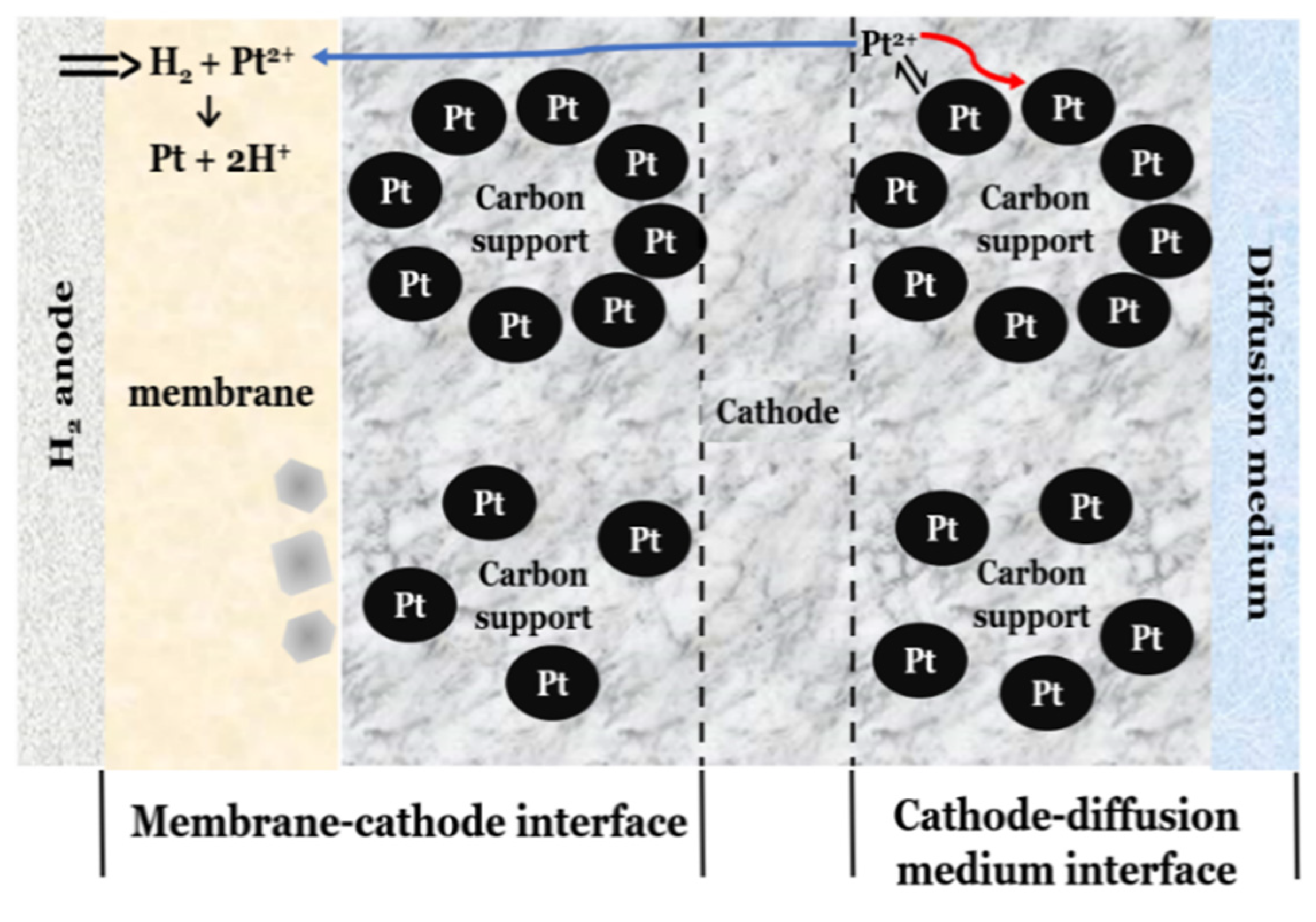
3.2.3. Pt/Ru Dissolution

Conventional Pt-Ru-based electrocatalysts are reported to comprehend a substantial quantity of unalloyed Ru in the form of intermetallic phases or segregated oxides, which are responsible for the dissolution of Ru under collapsed pseudocapacitive currents [160]. Pt or Ru dissolution from the Pt–Ru anode catalyst by potentials greater than 0.5 V vs. DHE, observed by migration and accumulation to the cathode can decrease the activity of both anode and cathode catalysts and a deterioration of cell performance [161]. Figure 9 [162] illustrates the Pt dissolution mechanism in a typical DMFC. In a study, it is reported that if the Pt/Ru atomic ratio is unchanged or decreased, it also can lead to Ru losses, relying on the comparative amount of Pt and Ru lost. The standard Pt/Ru atomic ratio of the Pt-Ru catalyst is 1:1, hence, a drop in Ru concentration in the catalyst leads to a decline in MOR. Nevertheless, based on the degree of alloying, the Pt–Ru catalyst’s MOR activity would increase after Ru loss [163].

3.2.4. Pt/Ru Delamination

Due to the low binding energy between the catalyst-coated membrane and the CLs, delamination of CLs often occurs throughout repetitive operations. The bonding force supplied by the direct pressing approach of CCM cannot withstand the swelling of the membrane during the operation of the DMFC, resulting in delamination [164]. A study reported that the isotropic membrane swelling (i.e., expansion coefficient difference between the CL and membrane) enhances the variance in swelling ratio with catalyst encompasses a Nafion binder, which would most likely increase electrode layer delamination [165].

3.2.5. Ru Leaching from Pt/Ru Catalyst

In the absence of Ru near the Pt catalyst, the firmly bonded CO molecule generated following reactant transfer will degrade the Pt surface. As a result, it is critical to avoid certain operating circumstances that lead to Ru leaching [166]. Additionally, the Ru leached from the anode will be deposited on the Nafion membrane, causing membrane fouling. Finally, the anode’s leached Ru can be deposited at the cathode, lowering the cathode catalyst’s total oxygen reduction activity. Though the existence of Ru is crucial for MOR, when the anode potential achieves 0.5 V vs. RHE, the Ru (in oxidized form) particles would be receptive to leaching [167]. By quantifying the amount of Ru oxide from various sections of the DMFC, we can ascertain that the potential distribution in the cell is not uniform even in a single cell arrangement under typical operating circumstances. Because of the comparatively large anodic potentials, this condition may also result in preferential Ru leaching from the methanol inflow area [168].

3.2.6. Surface Oxidation Formation and Practical Growth

The high binding energies of both CO and oxygen-containing species such as surface oxides or adsorbed OH groups induce the quite often substantiated poisoning of pure platinum utilized as an anodic catalyst [169]. Intermediate species may also poison the catalyst and deteriorate the fuel cell performance. For instance, methanol will partially oxidize to form intermediate species such as formic acid, methyl formate, and formaldehyde [170]. Pt surface oxidation at the cathode is investigated in numerous studies using the oxide reduction peak of cyclic-voltammetry measurements, and it is determined that the electrocatalytic activity for oxygen reduction decreases, which contributes to degradation in the catalyst layer [171]. The substantial, oxidized Ru percentage in the anode catalyst was demonstrated to exert a major influence in the development of particles at the anode side and was found to be disseminated throughout the cathode in its oxidized form and, therefore, can have a considerable impact on the oxygen reduction activity (ORR) [172].

3.2.7. Carbon Corrosion

Carbon black (specifically Vulcan XC-72) is the most frequently used backing layer for DMFCs. These are typically made using pyrolyzing hydrocarbons. The high surface area (∼250 m2 g−1 for Vulcan XC-72), low cost, and effortless accessibility of carbon black help decrease the total cost of the cell [173]. While widely used as a catalyst–support, CBs still endure complications such as (i) the presence of organo-sulfur impurities [174] and (ii) deep micropores or recesses which deceits the catalyst nanoparticles making them inaccessible to reactants consequently leading to reduced catalytic activity. Under the acidic environment of a conventional DMFC, thermochemical stability is essential, and its deficiency results in corrosion of the carbon support and dissolution of the catalyst layer [175]. Carbon black, on the other hand, is mostly made up of planar graphite carbon and amorphous carbon, both of which have a lot of dangling bonds and flaws. The dangling bonds quickly generate surface oxides, leading to a faster corrosion rate during electrochemical oxidation [176]. A study reported that agglomeration of catalysts which is triggered by reactant starvation is correlated to carbon support corrosion [177].

3.2.8. Mitigation Strategies for Catalyst Degradation

Among various degradation mechanisms, the Pt/Ru agglomeration and dissolution were found to be the most significant contributors to catalyst degradation in DMFCs. Therefore, considerable attention has been paid to reducing the catalysts agglomeration and dissolution. Pt/Ru supported on TiO2 embedded carbon nanofibers (Pt-Ru/TECNF), was reported as a highly active catalyst for methanol oxidation, which demonstrated reduced agglomeration compared to the conventional Pt catalysts supported on carbon [178,179]. A study reported that using ethanol solvent as catalyst ink for anode catalyst increased the interaction between Pt particles and ionomer, resulting in reduced agglomeration [180]. A similar study reported that using N-methyl pyrrolidone and dimethyl sulfoxide as catalyst ink enables the reduction of catalysts agglomeration [181]. Polyaniline-Silica (PANI-SiO2) nanocomposite was created as a support for improving the performance of Pt/Ni electrocatalysts, to improve catalyst stability. The Pt/Ni/SiO2-PANI electrocatalyst demonstrated exceptional catalytic activity. PANI-SiO2, as an organic–inorganic hybrid catalyst support, significantly increased the stability and CO poisoning tolerance of the resultant electrocatalyst, according to experimental and theoretical data [182]. A thin, permeable silicon oxide (SiOx) nanomembrane encapsulates a well-defined Pt thin film (SiOx/Pt), is used as a catalyst-coated membrane to improve durability. The proposed catalyst demonstrated exceptional CO tolerance and highly active methanol oxidation, which also shows an improved lifespan compared to conventional catalyst [183]. TiO2-Fe2O3@SiO2-incorporated graphene oxide nanohybrid prepared by the hydrothermal method was used as a catalyst for DMFC. The nanohybrid showed greater stability with 91.58% retaining the initial current density later on 5000 s in the life span current–time curve [184]. Nickel–palladium supported onto mesostructured silica nanoparticles (NiPd–MSN) was used as an electrocatalyst for DMFC. The results of the study showed greater stability toward oxidation with 61% current retention and superior tolerance to the carbonaceous species accumulation compared with other electrocatalysts [185]. Poly(3,4-ethyl) (PEDOT) backed with carbon-supported Pt is used as anode catalysts for DMFC methanol oxidation which exhibits high mass activity and superior stability after 500 durability cycles, which is greater than those of commercial Pt/C catalyst [186]. A study demonstrated a dual-template approach to produce well-defined cage-bell nanostructures containing Pt core and a mesoporous PtM (M ¼ Co, Ni) bimetallic shell (Pt@mPtM (M ¼ Co, Ni) CB). The unique nanostructure and bimetallic properties of Pt@mPtM (M ¼ Co, Ni) CBs showed higher catalytic activity, superior durability, and greater CO tolerance for the methanol oxidation reaction than commercial Pt/C [187].

3.3. Gas Diffusion Layer

GDL is the most often overlooked cell component subjected to degradation in the DMFC system. This is attributed to the fact that the GDL degradation is much limited by the factors such as cell potential, porosity, and the effect due to the temperature.

3.3.1. Cell Potential

The diffusion layers are usually made of a carbon cloth or carbon paper that contributes a substantial role to the species transportation and structural integrity of MEA for PEM and any alcohol fuel cells [188]. The carbon base provides DMFCs with fairly good electrical conductivity between the catalyst and current collecting plates [189]. In general, GDL is around 100–400 µm thick and porous, which permits gas diffusion to the catalyst. Thinner layers are normally better as they possess nominal electrical resistance and let fuel and oxidants effortlessly pass through [190]. Nevertheless, carbon corrosion occurs at different voltage rates under several fuel cell operating conditions; however, the severity is low compared to a H2-based PEM fuel cell as the nominal operating voltage is low for DMFC [191].

3.3.2. Porosity

GDL porosity can also be one of the parameters that can impact its durability and performance. The GDL is frequently wet-proofed with a hydrophobic material such as Teflon® (PTFE). The hydrophobic material permits excess water rejection, thereby inhibiting flooding [192,193]. The primary physical parameters influencing GDL degradation are the gas permeability and the pore size diameter [194]. A study reported that the optimal pore size diameter to be around 25–40 µm, and greater than that would result in excess flooding, which degrades the GDL; however, increased porosity increases the current density [195]. The Teflon® content and GDL thickness thus proven to have a larger impact on GDL degradation just than the porosity [196].

3.3.3. Operating Temperature

Limited water diffusion through the cathode GDL leads to flooding, and too much water diffusion can lead to cathode active layer and the polymer membrane dry triggering excessive cell resistance, which is called Ohmic polarization [197]. An increase in cell temperature than the standard defined level (60–100 °C) tends to dry the GDL, which consequently results in degradation [198]. On the other hand, low operating temperature is affected due to the progressive damage in carbon fiber and due to the change in the structure of the microporous layer [199]. Nevertheless, at higher operating temperatures, inherent mechanical characteristics of the GDL were drastically affected by the temperature-dependent parameters of the PTFE and epoxy resin resulting in a considerable reduction in resistance to GDL compression than found at lower operating temperatures [200].

3.3.4. Mitigation Strategies of GDL Degradation

The critical aspect impeding the output performance of conventional DMFCs is the minimum efficiency of the mass transport of oxygen, which is often a result of water flooding. Currently, researchers are largely determined on the water back diffusion from the cathode to the anode, as this can potentially solve the flooding at the cathode and decrease methanol crossover. A new hybrid catalyst layer (CL) was described in a study where relatively hydrophobic and hydrophilic CLs were integrated to form a hybrid CL [201]. The results of the study showed that the hydrophilic and hydrophobic control can efficiently generate a better distribution of methanol and water concentration. A three-dimensional graphene framework was applied to manufacture cathode MPL for improving water management [202]. The results indicated that the performance and stability were improved remarkably. From the literature review, water back diffusion improvement is an efficient approach for water management, inhibiting cathode flooding and reducing the MCO from the anode to the cathode. Though substantial improvements have been attained using the aforesaid techniques, the oxygen mass transport within the catalyst layer is however a challenge. A trilaminar-catalytic layered GDL design could accelerate the water back diffusion and encourage oxygen mass transportation. In a study, a trilaminar-catalytic layer comprises an inner, middle, and outer layer that is used for DMFC [203]. The middle layer has lower porosity compared to the inner and outer layers. This produces a water pressure gradient between the inner and middle layers and an oxygen concentration gradient between the outer and middle layers. Thus, the trilaminar-catalytic layered MEA can enhance water back diffusion from the cathode to the anode, as well as oxygen mass transportation, by creating beneficial gradients. An optimized MPL design is crucial to mitigate methanol crossover and improve DMFC performance. A study on the effects of MPL design in a DMFC indicated that anode MPL decreases the methanol concentration and liquid saturation in the anode CL. Cathode MPL improves the water back-flow from the cathode to the anode and Hydrophobic anode CL improves the water back-flow from the cathode to anode [204]. A study on the effect of porosity of the copper-fibre sintered felt (CFSF) demonstrated that GDL with a super-hydrophobic pattern that has a porosity of 60% attains the best performance compared to those of 50% and 70% porous, since it facilitates water removal when the water balance coefficient (WBC) is high [205].

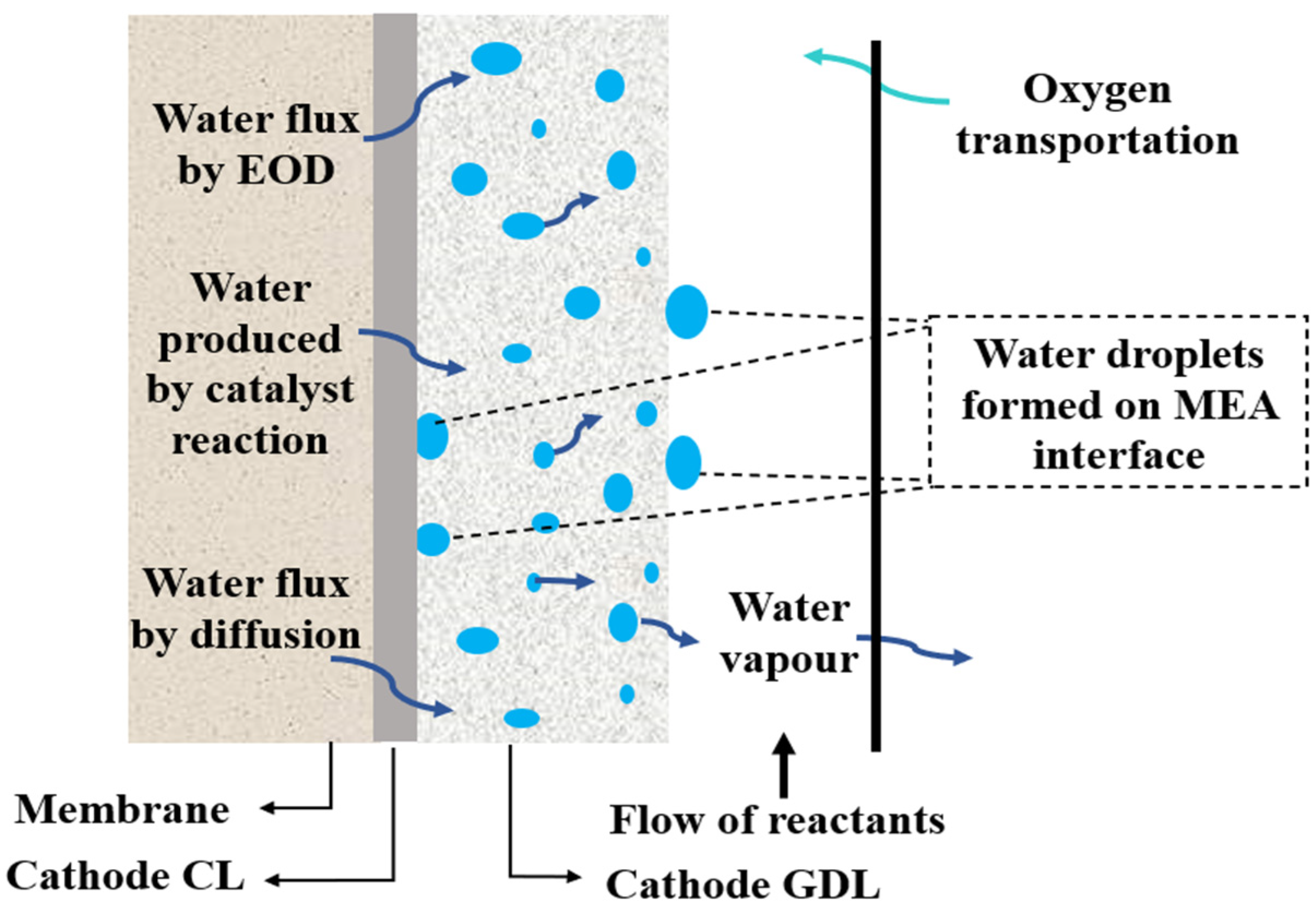
4. Influence of Water Flooding in MEA Degradation

Cathode flooding of DMFC is a key contributor to the recoverable operational losses in DMFCs. Cathode flooding is categorized as catalyst flooding and backing flooding. Catalyst flooding is associated with several ORR active sites, the catalyst thickness, pore size, and its distribution [206]. The backing flooding is associated with the hydrophobicity and porosity of the backing layer [207]. Figure 10 [208] depicts the schematic representation of the water flooding mechanism in DMFC. The effect of cathode flooding in DMFC is considerably hazardous than a PEMFC, because of the aqueous methanol feed in the anode [209]. Almost 80% of the overall water content of DMFC cathode originates from the anode side, primarily through diffusion and electro-osmotic drag processes. This mostly degrades the initial fuel cell efficiency and also leads to excessive voltage drop rates throughout prolonged operation [210].
In general, DMFCs provide stable performance during the initial phase of a durability test. However, when the operating period is expanded, voltage loss is accelerated owing to water accumulation [211]. Water flooding intensifies with time and is known to effectively halt the operation of DMFC after only a few hundred hours of operation, particularly while catalyst-coated membrane (CCM)-type MEAs are employed. The following performance recovery of a DMFC can be achieved by cathode drying over longer durations, that could be as extensive as a few days [212]. Water flooding in a DMFC is commonly ascribed to a lack of hydrophobicity in the cathode GDL/MPL due to the dispersion of the poly-tetrafluoroethylene (PTFE) additive [213]. However, emphasizing the loss of GDL hydrophobic character as the sole reason over such an early phase of cathode flooding acceleration led to a misinterpretation of the precise accelerated rate of structural changes of GDL and potentially trigger an overlook of the significant contribution by morphological changes in the CCL [214]. In a study, using the Sessile-drop method, it is observed that decreasing hydrophobicity leads to a small contact angle of water droplets in the GDL fibers [215]. Despite the irreversible performance reduction, there is a chance that the physical degradation of electrodes, especially the cathode, will have implications for water drainage characteristics during a prolonged test, potentially increasing the water flooding conflict [216]. However, the number of lite is limited with linked water flooding behavior to morphological alterations in the CCL during protracted DMFC operation.

5. Conclusions

The DMFCs have the potential to play an important role in the future, specifically in replacing the Li-ion-based batteries for able and military applications. Inadequate reliability can potentially impede the commercialization of DMFCs. As a consequence, a reliability assessment can provide more insight into the component’s attributes. Therefore, the present assessment emphasized the general degradation mechanism of MEA components of DMFCs. Incidentally, the durability of the MEA components needs to be circumvented for these systems to penetrate the market; specifically, the long-term durability of these systems should range from 3000 to 5000 operating hours. Aside from the durability of MEA components, operational methods and design can have a substantial influence on the durability characteristics of MEA, which might be a prerequisite for MEA robustness. This critical assessment can improve the reliability and, subsequently, complement the market penetration at a faster rate through a structured procedure which can be potentially useful for DMFC research. In this work, the reliability analysis is also carried out with the basic structured procedure, while excluding the system modelling and quantitative/qualitative analysis.
The authors believe that a systematic root cause analysis or a fault tree analysis (FTA) method of the present literature can help DMFC researchers and manufacturers to gain a holistic insight into the durability mechanism in a simple yet effective manner.

Author Contributions

Conceptualization, A.J., D.K.M. and N.M.K.; resources, A.J. and N.M.K.; data curation, A.J. and N.M.K.; writing—original draft preparation, A.J., D.K.M. and N.M.K.; writing—review and editing, A.J. and N.M.K.; visualization, D.K.M.; supervision, N.M.K.; project administration, A.J. and N.M.K. All authors have read and agreed to the published version of the manuscript.

Funding

This research received no external funding.

Institutional Review Board Statement

Not applicable.

Informed Consent Statement

Not applicable.

Data Availability Statement

Not applicable.

Acknowledgments

The author(s) would like to acknowledge the technical support from SusSo Foundation Cares, a Non-profitable Organization (NPO), India.

Conflicts of Interest

The authors declare no conflict of interest.

References

  1. Chakraborty, S.; Kumar, N.M.; Jayakumar, A.; Dash, S.K.; Elangovan, D. Selected Aspects of Sustainable Mobility Reveals Implementable Approaches and Conceivable Actions. Sustainability 2021, 13, 12918. [Google Scholar] [CrossRef]
  2. Jayakumar, A. An Assessment on Polymer Electrolyte Membrane Fuel Cell Stack Components. In Applied Physical Chemistry with Multidisciplinary Approaches; Apple Academic Press: Cambridge, MA, USA, 2018; ISBN 978-1-315-16941-5. [Google Scholar]
  3. Sun, C.; Negro, E.; Vezzù, K.; Pagot, G.; Cavinato, G.; Nale, A.; Herve Bang, Y.; Di Noto, V. Hybrid Inorganic-Organic Proton-Conducting Membranes Based on SPEEK Doped with WO3 Nanoparticles for Application in Vanadium Redox Flow Batteries. Electrochim. Acta 2019, 309, 311–325. [Google Scholar] [CrossRef]
  4. Garraín, D.; Banacloche, S.; Ferreira-Aparicio, P.; Martínez-Chaparro, A.; Lechón, Y. Sustainability Indicators for the Manufacturing and Use of a Fuel Cell Prototype and Hydrogen Storage for Portable Uses. Energies 2021, 14, 6558. [Google Scholar] [CrossRef]
  5. Cost-Effective Iron-Based Aqueous Redox Flow Batteries for Large-Scale Energy Storage Application: A Review. J. Power Sources 2021, 493, 229445. [CrossRef]
  6. Wu, F.; Maier, J.; Yu, Y. Guidelines and Trends for Next-Generation Rechargeable Lithium and Lithium-Ion Batteries. Chem. Soc. Rev. 2020, 49, 1569–1614. [Google Scholar] [CrossRef]
  7. Staffell, I.; Scamman, D.; Abad, A.V.; Balcombe, P.; Dodds, P.E.; Ekins, P.; Shah, N.; Ward, K.R. The Role of Hydrogen and Fuel Cells in the Global Energy System. Energy Environ. Sci. 2019, 12, 463–491. [Google Scholar] [CrossRef] [Green Version]
  8. Halme, A.; Selkäinaho, J.; Noponen, T.; Kohonen, A. An Alternative Concept for DMFC—Combined Electrolyzer and H2 PEMFC. Int. J. Hydrogen Energy 2016, 41, 2154–2164. [Google Scholar] [CrossRef]
  9. Munjewar, S.S.; Thombre, S.B.; Patil, A.P. Passive Direct Alcohol Fuel Cell Using Methanol and 2-Propanol Mixture as a Fuel. Ionics 2019, 25, 2231–2241. [Google Scholar] [CrossRef]
  10. Cheng, Y.; Zhang, J.; Lu, S.; Jiang, S.P. Significantly Enhanced Performance of Direct Methanol Fuel Cells at Elevated Temperatures. J. Power Sources 2020, 450, 227620. [Google Scholar] [CrossRef]
  11. Dao, D.V.; Adilbish, G.; Le, T.D.; Nguyen, T.T.D.; Lee, I.-H.; Yu, Y.-T. Au@CeO2 Nanoparticles Supported Pt/C Electrocatalyst to Improve the Removal of CO in Methanol Oxidation Reaction. J. Catal. 2019, 377, 589–599. [Google Scholar] [CrossRef]
  12. Badwal, S.P.S.; Giddey, S.; Kulkarni, A.; Goel, J.; Basu, S. Direct Ethanol Fuel Cells for Transport and Stationary Applications—A Comprehensive Review. Appl. Energy 2015, 145, 80–103. [Google Scholar] [CrossRef]
  13. Pan, Z.; Bi, Y.; An, L. Mathematical Modeling of Direct Ethylene Glycol Fuel Cells Incorporating the Effect of the Competitive Adsorption. Appl. Therm. Eng. 2019, 147, 1115–1124. [Google Scholar] [CrossRef]
  14. Chu, Y.H.; Shul, Y.G. Combinatorial Investigation of Pt–Ru–Sn Alloys as an Anode Electrocatalysts for Direct Alcohol Fuel Cells. Int. J. Hydrogen Energy 2010, 35, 11261–11270. [Google Scholar] [CrossRef]
  15. Achmad, F.; Kamarudin, S.K.; Daud, W.R.W.; Majlan, E.H. Passive Direct Methanol Fuel Cells for Portable Electronic Devices. Appl. Energy 2011, 88, 1681–1689. [Google Scholar] [CrossRef]
  16. Bahrami, H.; Faghri, A. Review and Advances of Direct Methanol Fuel Cells: Part II: Modeling and Numerical Simulation. J. Power Sources 2013, 230, 303–320. [Google Scholar] [CrossRef]
  17. Mallick, R.K.; Thombre, S.B.; Shrivastava, N.K. Vapor Feed Direct Methanol Fuel Cells (DMFCs): A Review. Renew. Sustain. Energy Rev. 2016, 56, 51–74. [Google Scholar] [CrossRef]
  18. Falcão, D.S.; Oliveira, V.B.; Rangel, C.M.; Pinto, A.M.F.R. Review on Micro-Direct Methanol Fuel Cells. Renew. Sustain. Energy Rev. 2014, 34, 58–70. [Google Scholar] [CrossRef] [Green Version]
  19. Karimi, M.B.; Mohammadi, F.; Hooshyari, K. Recent Approaches to Improve Nafion Performance for Fuel Cell Applications: A Review. Int. J. Hydrogen Energy 2019, 44, 28919–28938. [Google Scholar] [CrossRef]
  20. Lufrano, F.; Baglio, V.; Staiti, P.; Antonucci, V.; Arico’, A.S. Performance Analysis of Polymer Electrolyte Membranes for Direct Methanol Fuel Cells. J. Power Sources 2013, 243, 519–534. [Google Scholar] [CrossRef]
  21. Pethaiah, S.S.; Arunkumar, J.; Ramos, M.; Al-Jumaily, A.; Manivannan, N. The Impact of Anode Design on Fuel Crossover of Direct Ethanol Fuel Cell. Bull. Mater. Sci. 2016, 39, 273–278. [Google Scholar] [CrossRef] [Green Version]
  22. Kumar, P.; Dutta, K.; Das, S.; Kundu, P.P. An Overview of Unsolved Deficiencies of Direct Methanol Fuel Cell Technology: Factors and Parameters Affecting Its Widespread Use. Int. J. Energy Res. 2014, 38, 1367–1390. [Google Scholar] [CrossRef]
  23. Park, J.-Y.; Park, K.-Y.; Kim, K.B.; Na, Y.; Cho, H.; Kim, J.-H. Influence and Mitigation Methods of Reaction Intermediates on Cell Performance in Direct Methanol Fuel Cell System. J. Power Sources 2011, 196, 5446–5452. [Google Scholar] [CrossRef]
  24. Bresciani, F.; Rabissi, C.; Zago, M.; Gazdzicki, P.; Schulze, M.; Guétaz, L.; Escribano, S.; Bonde, J.L.; Marchesi, R.; Casalegno, A. A Combined In-Situ and Post-Mortem Investigation on Local Permanent Degradation in a Direct Methanol Fuel Cell. J. Power Sources 2016, 306, 49–61. [Google Scholar] [CrossRef]
  25. Kreuer, K.-D. Ion Conducting Membranes for Fuel Cells and Other Electrochemical Devices. Chem. Mater. 2014, 26, 361–380. [Google Scholar] [CrossRef]
  26. Ahmad, H.; Kamarudin, S.K.; Hasran, U.A.; Daud, W.R.W. Overview of Hybrid Membranes for Direct-Methanol Fuel-Cell Applications. Int. J. Hydrogen Energy 2010, 35, 2160–2175. [Google Scholar] [CrossRef]
  27. Kim, D.S.; Guiver, M.; McGrath, J.; Pivovar, B.; Kim, Y.S. Molecular Design Aspect of Sulfonated Polymers for Direct Methanol Fuel Cells. ECS Trans. 2010, 33, 711. [Google Scholar] [CrossRef] [Green Version]
  28. Sharma, S. Membranes for Low Temperature Fuel Cells: New Concepts, Single-Cell Studies and Applications; De Gruyter: Berlin, Germany, 2019; ISBN 978-3-11-064732-7. [Google Scholar]
  29. Lin, H.-L.; Wang, S.-H. Nafion/Poly(Vinyl Alcohol) Nano-Fiber Composite and Nafion/Poly(Vinyl Alcohol) Blend Membranes for Direct Methanol Fuel Cells. J. Membr. Sci. 2014, 452, 253–262. [Google Scholar] [CrossRef]
  30. Choi, J.S.; Sohn, J.-Y.; Shin, J. A Comparative Study on EB-Radiation Deterioration of Nafion Membrane in Water and Isopropanol Solvents. Energies 2015, 8, 5370–5380. [Google Scholar] [CrossRef] [Green Version]
  31. Aydın Ünal, F.; Erduran, V.; Timuralp, C.; Şen, F. 15—Fabrication and Properties of Polymer Electrolyte Membranes (PEM) for Direct Methanol Fuel Cell Application. In Nanomaterials for Direct Alcohol Fuel Cells; Şen, F., Ed.; Micro and Nano Technologies; Elsevier: Amsterdam, The Netherlands, 2021; pp. 283–302. ISBN 978-0-12-821713-9. [Google Scholar]
  32. Ercelik, M.; Ozden, A.; Devrim, Y.; Colpan, C.O. Investigation of Nafion Based Composite Membranes on the Performance of DMFCs. Int. J. Hydrogen Energy 2017, 42, 2658–2668. [Google Scholar] [CrossRef]
  33. Wang, J.; Liao, J.; Yang, L.; Zhang, S.; Huang, X.; Ji, J. Highly Compatible Acid–Base Blend Membranes Based on Sulfonated Poly(Ether Ether Ketone) and Poly(Ether Ether Ketone-Alt-Benzimidazole) for Fuel Cells Application. J. Membr. Sci. 2012, 415–416, 644–653. [Google Scholar] [CrossRef]
  34. Liu, C.; Wang, X.; Xu, J.; Wang, C.; Chen, H.; Liu, W.; Chen, Z.; Du, X.; Wang, S.; Wang, Z. PEMs with High Proton Conductivity and Excellent Methanol Resistance Based on Sulfonated Poly (Aryl Ether Ketone Sulfone) Containing Comb-Shaped Structures for DMFCs Applications. Int. J. Hydrogen Energy 2020, 45, 945–957. [Google Scholar] [CrossRef]
  35. Dutta, K.; Das, S.; Kundu, P.P. Synthesis, Preparation, and Performance of Blends and Composites of π-Conjugated Polymers and Their Copolymers in DMFCs. Polym. Rev. 2015, 55, 630–677. [Google Scholar] [CrossRef]
  36. Kludský, M.; Vopička, O.; Matějka, P.; Hovorka, Š.; Friess, K. Nafion® Modified with Primary Amines: Chemical Structure, Sorption Properties and Pervaporative Separation of Methanol-Dimethyl Carbonate Mixtures. Eur. Polym. J. 2018, 99, 268–276. [Google Scholar] [CrossRef]
  37. Klose, C.; Breitwieser, M.; Vierrath, S.; Klingele, M.; Cho, H.; Büchler, A.; Kerres, J.; Thiele, S. Electrospun Sulfonated Poly(Ether Ketone) Nanofibers as Proton Conductive Reinforcement for Durable Nafion Composite Membranes. J. Power Sources 2017, 361, 237–242. [Google Scholar] [CrossRef]
  38. Pérez, L.C.; Brandão, L.; Sousa, J.M.; Mendes, A. Segmented Polymer Electrolyte Membrane Fuel Cells—A Review. Renew. Sustain. Energy Rev. 2011, 15, 169–185. [Google Scholar] [CrossRef]
  39. Prokop, M.; Kodym, R.; Bystron, T.; Drakselova, M.; Paidar, M.; Bouzek, K. Degradation Kinetics of Pt during High-Temperature PEM Fuel Cell Operation Part II: Dissolution Kinetics of Pt Incorporated in a Catalyst Layer of a Gas-Diffusion Electrode. Electrochim. Acta 2020, 333, 135509. [Google Scholar] [CrossRef]
  40. Kamarudin, S.K.; Hashim, N. Materials, Morphologies and Structures of MEAs in DMFCs. Renew. Sustain. Energy Rev. 2012, 16, 2494–2515. [Google Scholar] [CrossRef]
  41. Xinyao, Y.; Zhongqing, J.; Yuedong, M. Preparation of Anodes for DMFC by Co-Sputtering of Platinum and Ruthenium. Plasma Sci. Technol. 2010, 12, 224–229. [Google Scholar] [CrossRef]
  42. Dutta, K.; Das, S.; Rana, D.; Kundu, P.P. Enhancements of Catalyst Distribution and Functioning Upon Utilization of Conducting Polymers as Supporting Matrices in DMFCs: A Review. Polym. Rev. 2015, 55, 1–56. [Google Scholar] [CrossRef]
  43. Gulaboski, R.; Mirceski, V.; Komorsky-Lovric, S.; Lovric, M. Three-Phase Electrodes: Simple and Efficient Tool for Analysis of Ion Transfer Processes across Liquid-Liquid Interface—Twenty Years On. J Solid State Electrochem. 2020, 24, 2575–2583. [Google Scholar] [CrossRef]
  44. Li, Q.; Wang, T.; Havas, D.; Zhang, H.; Xu, P.; Han, J.; Cho, J.; Wu, G. High-Performance Direct Methanol Fuel Cells with Precious-Metal-Free Cathode. Adv. Sci. 2016, 3, 1600140. [Google Scholar] [CrossRef] [PubMed] [Green Version]
  45. Sgroi, M.F.; Zedde, F.; Barbera, O.; Stassi, A.; Sebastián, D.; Lufrano, F.; Baglio, V.; Aricò, A.S.; Bonde, J.L.; Schuster, M. Cost Analysis of Direct Methanol Fuel Cell Stacks for Mass Production. Energies 2016, 9, 1008. [Google Scholar] [CrossRef]
  46. Samad, S.; Loh, K.S.; Wong, W.Y.; Lee, T.K.; Sunarso, J.; Chong, S.T.; Wan Daud, W.R. Carbon and Non-Carbon Support Materials for Platinum-Based Catalysts in Fuel Cells. Int. J. Hydrogen Energy 2018, 43, 7823–7854. [Google Scholar] [CrossRef]
  47. Khotseng, L. Oxygen Reduction Reaction; IntechOpen: Gujarat, India, 2018; ISBN 978-1-78984-813-7. [Google Scholar]
  48. Yan, X.H.; Zhao, T.S.; An, L.; Zhao, G.; Zeng, L. A Crack-Free and Super-Hydrophobic Cathode Micro-Porous Layer for Direct Methanol Fuel Cells. Appl. Energy 2015, 138, 331–336. [Google Scholar] [CrossRef]
  49. Abdelkareem, M.A.; Sayed, E.T.; Nakagawa, N. Significance of Diffusion Layers on the Performance of Liquid and Vapor Feed Passive Direct Methanol Fuel Cells. Energy 2020, 209, 118492. [Google Scholar] [CrossRef]
  50. Ivanova, N.A.; Alekseeva, O.K.; Fateev, V.N.; Shapir, B.L.; Spasov, D.D.; Nikitin, S.M.; Presnyakov, M.Y.; Kolobylina, N.N.; Soloviev, M.A.; Mikhalev, A.I.; et al. Activity and Durability of Electrocatalytic Layers with Low Platinum Loading Prepared by Magnetron Sputtering onto Gas Diffusion Electrodes. Int. J. Hydrogen Energy 2019, 44, 29529–29536. [Google Scholar] [CrossRef]
  51. Netzeband, C.; Arlt, T.; Wippermann, K.; Lehnert, W.; Manke, I. Three-Dimensional Multiscale Analysis of Degradation of Nano- and Micro-Structure in Direct Methanol Fuel Cell Electrodes after Methanol Starvation. J. Power Sources 2016, 327, 481–487. [Google Scholar] [CrossRef]
  52. Nagy, K.A.; Tóth, I.Y.; Ballai, G.; Varga, Á.T.; Szenti, I.; Sebők, D.; Kopniczky, J.; Hopp, B.; Kukovecz, Á. Wetting and Evaporation on a Carbon Cloth Type Gas Diffusion Layer for Passive Direct Alcohol Fuel Cells. J. Mol. Liq. 2020, 304, 112698. [Google Scholar] [CrossRef]
  53. Poplavsky, V.V.; Dorozhko, A.V.; Matys, V.G. Ion-Beam Formation of Electrocatalysts for Fuel Cells with Polymer Membrane Electrolyte. J. Synch. Investig. 2017, 11, 326–332. [Google Scholar] [CrossRef]
  54. Liu, G.; Li, X.; Wang, M.; Wang, M.; Kim, J.Y.; Woo, J.Y.; Wang, X.; Lee, J.K. A Study on Anode Diffusion Layer for Performance Enhancement of a Direct Methanol Fuel Cell. Energy Convers. Manag. 2016, 126, 697–703. [Google Scholar] [CrossRef]
  55. Falcão, D.S.; Silva, R.A.; Rangel, C.M.; Pinto, A.M.F.R. Performance of an Active Micro Direct Methanol Fuel Cell Using Reduced Catalyst Loading MEAs. Energies 2017, 10, 1683. [Google Scholar] [CrossRef] [Green Version]
  56. Hsieh, S.-S.; Hung, L.-C.; Liu, C.-C.; Huang, C.-F. Analyses of Electrochemical Impedance Spectroscopy and Cyclic Voltammetry in Micro-Direct Methanol Fuel Cell Stacks. Int. J. Energy Res. 2016, 40, 2162–2175. [Google Scholar] [CrossRef]
  57. Rashed, M.K.; Mohd Salleh, M.A.; Abdulbari, H.A.; Shah Ismail, M.H.; Izhar, S. The Effects of Electrode and Catalyst Selection on Microfluidic Fuel Cell Performance. ChemBioEng Rev. 2015, 2, 356–372. [Google Scholar] [CrossRef]
  58. Gauthier, E.; Benziger, J.B. Gas Management and Multiphase Flow in Direct Alcohol Fuel Cells. Electrochim. Acta 2014, 128, 238–247. [Google Scholar] [CrossRef]
  59. Xue, R.; Zhang, Y.; Liu, X. A Novel Cathode Gas Diffusion Layer for Water Management of Passive μ-DMFC. Energy 2017, 139, 535–541. [Google Scholar] [CrossRef]
  60. Yuan, W.; Tang, Y.; Yang, X.; Liu, B.; Wan, Z. Structural Diversity and Orientation Dependence of a Liquid-Fed Passive Air-Breathing Direct Methanol Fuel Cell. Int. J. Hydrogen Energy 2012, 37, 9298–9313. [Google Scholar] [CrossRef]
  61. Yi, P.; Peng, L.; Lai, X.; Li, M.; Ni, J. Investigation of Sintered Stainless Steel Fiber Felt as Gas Diffusion Layer in Proton Exchange Membrane Fuel Cells. Int. J. Hydrogen Energy 2012, 37, 11334–11344. [Google Scholar] [CrossRef]
  62. Zhao, Z.; Zhang, F.; Zhang, Y.; Zhang, D. Performance Optimization of ΜDMFC with Foamed Stainless Steel Cathode Current Collector. Energies 2021, 14, 6608. [Google Scholar] [CrossRef]
  63. Zhang, J.; Zhu, Y.L.; Qi, G.; Li, J.Y. Current Development of Key Materials for Low Temperature Fuel Cells. Key Eng. Mater. 2017, 727, 670–677. [Google Scholar] [CrossRef]
  64. Madheswaran, D.K.; Jayakumar, A. Recent Advancements on Non-Platinum Based Catalyst Electrode Material for Polymer Electrolyte Membrane Fuel Cells: A Mini Techno-Economic Review. Bull. Mater. Sci. 2021, 44, 287. [Google Scholar] [CrossRef]
  65. Yao, D.; Jao, T.-C.; Zhang, W.; Xu, L.; Xing, L.; Ma, Q.; Xu, Q.; Li, H.; Pasupathi, S.; Su, H. In-Situ Diagnosis on Performance Degradation of High Temperature Polymer Electrolyte Membrane Fuel Cell by Examining Its Electrochemical Properties under Operation. Int. J. Hydrogen Energy 2018, 43, 21006–21016. [Google Scholar] [CrossRef]
  66. Han, J.; Han, J.; Yu, S. Experimental Analysis of Performance Degradation of 3-Cell PEMFC Stack under Dynamic Load Cycle. Int. J. Hydrogen Energy 2020, 45, 13045–13054. [Google Scholar] [CrossRef]
  67. Chu, T.; Zhang, R.; Wang, Y.; Ou, M.; Xie, M.; Shao, H.; Yang, D.; Li, B.; Ming, P.; Zhang, C. Performance Degradation and Process Engineering of the 10 KW Proton Exchange Membrane Fuel Cell Stack. Energy 2021, 219, 119623. [Google Scholar] [CrossRef]
  68. Casalegno, A.; Bresciani, F.; Zago, M.; Marchesi, R. Experimental Investigation of Methanol Crossover Evolution during Direct Methanol Fuel Cell Degradation Tests. J. Power Sources 2014, 249, 103–109. [Google Scholar] [CrossRef]
  69. Shrivastava, N.K.; Chadge, R.B.; Bankar, S.L. Modelling and Simulation of Passive Feed Direct Methanol Fuel Cell. Int. J. Energy Technol. Policy 2017, 13, 4–18. [Google Scholar] [CrossRef]
  70. Direct Methanol Fuel Cell Methanol and Water Crossover. Available online: https://www.wpclipart.com/science/how_things_work/Direct_Methanol_Fuel_Cell__Methanol_and_Water_Crossover.png.html (accessed on 13 November 2021).
  71. Xu, C.; Faghri, A.; Li, X.; Ward, T. Methanol and Water Crossover in a Passive Liquid-Feed Direct Methanol Fuel Cell. Int. J. Hydrogen Energy 2010, 35, 1769–1777. [Google Scholar] [CrossRef]
  72. Sharifi, S.; Rahimi, R.; Mohebbi-Kalhori, D.; Colpan, C.O. Numerical Investigation of Methanol Crossover through the Membrane in a Direct Methanol Fuel Cell. Iran. J. Hydrog. Fuel Cell 2018, 5, 21–33. [Google Scholar] [CrossRef]
  73. Chi, N.T.Q.; Bae, B.; Kim, D. Electro-Osmotic Drag Effect on the Methanol Permeation for Sulfonated Poly(Ether Ether Ketone) and Nafion117 Membranes. J. Nanosci. Nanotechnol. 2013, 13, 7529–7534. [Google Scholar] [CrossRef]
  74. García-Nieto, D.; Barragán, V.M. A Comparative Study of the Electro-Osmotic Behavior of Cation and Anion Exchange Membranes in Alcohol-Water Media. Electrochim. Acta 2015, 154, 166–176. [Google Scholar] [CrossRef]
  75. Endo, N.; Ogawa, Y.; Ukai, K.; Kakihana, Y.; Higa, M. DMFC Performance of Polymer Electrolyte Membranes Prepared from a Graft-Copolymer Consisting of a Polysulfone Main Chain and Styrene Sulfonic Acid Side Chains. Energies 2016, 9, 658. [Google Scholar] [CrossRef] [Green Version]
  76. Huang, K.-L.; Liao, Y.-H.; Chen, S.-J. Effects of Operating Parameters on Gas-Phase PAH Emissions from a Direct Methanol Fuel Cell. Aerosol Air Qual. Res. 2019, 19, 2196–2204. [Google Scholar] [CrossRef]
  77. Yuan, Z.; Chuai, W.; Guo, Z.; Tu, Z.; Kong, F. The Self-Adaptive Fuel Supply Mechanism in Micro DMFC Based on the Microvalve. Micromachines 2019, 10, 353. [Google Scholar] [CrossRef] [PubMed] [Green Version]
  78. Araya, S.S.; Andreasen, S.J.; Kær, S.K. Experimental Characterization of the Poisoning Effects of Methanol-Based Reformate Impurities on a PBI-Based High Temperature PEM Fuel Cell. Energies 2012, 5, 4251. [Google Scholar] [CrossRef]
  79. Bogolowski, N.; Drillet, J.-F. Appropriate Balance between Methanol Yield and Power Density in Portable Direct Methanol Fuel Cell. Chem. Eng. J. 2015, 270, 91–100. [Google Scholar] [CrossRef]
  80. Ji, F.; Yang, L.; Sun, H.; Wang, S.; Li, H.; Jiang, L.; Sun, G. A Novel Method for Analysis and Prediction of Methanol Mass Transfer in Direct Methanol Fuel Cell. Energy Convers. Manag. 2017, 154, 482–490. [Google Scholar] [CrossRef]
  81. Ramesh, V.; Krishnamurthy, B. Modeling the Transient Temperature Distribution in a Direct Methanol Fuel Cell. J. Electroanal. Chem. 2018, 809, 1–7. [Google Scholar] [CrossRef]
  82. Govindarasu, R.; Somasundaram, S. Studies on Influence of Cell Temperature in Direct Methanol Fuel Cell Operation. Processes 2020, 8, 353. [Google Scholar] [CrossRef] [Green Version]
  83. Andoh, S.; Fujita, A.; Miitsu, T.; Kuroda, Y.; Mitsushima, S. Practical and Reliable Methanol Concentration Sensor for Direct Methanol Fuel Cells. Electrochemistry 2021, 89, 250–255. [Google Scholar] [CrossRef]
  84. Tsen, W.-C. Composite Proton Exchange Membranes Based on Chitosan and Phosphotungstic Acid Immobilized One-Dimensional Attapulgite for Direct Methanol Fuel Cells. Nanomaterials 2020, 10, 1641. [Google Scholar] [CrossRef]
  85. Sudaroli, B.M.; Kolar, A.K. An Experimental Study on the Effect of Membrane Thickness and PTFE (Polytetrafluoroethylene) Loading on Methanol Crossover in Direct Methanol Fuel Cell. Energy 2016, 98, 204–214. [Google Scholar] [CrossRef]
  86. Gwak, G.; Lee, K.; Ferekh, S.; Lee, S.; Ju, H. Analyzing the Effects of Fluctuating Methanol Feed Concentration in Active-Type Direct Methanol Fuel Cell (DMFC) Systems. Int. J. Hydrogen Energy 2015, 40, 5396–5407. [Google Scholar] [CrossRef]
  87. Zhang, C.; Yue, X.; Yang, Y.; Lu, N.; Zhang, S.; Wang, G. Thin and Methanol-Resistant Reinforced Composite Membrane Based on Semi-Crystalline Poly (Ether Ether Ketone) for Fuel Cell Applications. J. Power Sources 2020, 450, 227664. [Google Scholar] [CrossRef]
  88. Wippermann, K.; Klafki, K.; Kulikovsky, A.A. In Situ Measurement of the Oxygen Diffusion Coefficient in the Cathode Catalyst Layer of a Direct Methanol Fuel Cell. Electrochim. Acta 2014, 141, 212–215. [Google Scholar] [CrossRef]
  89. Gago, A.S.; Esquivel, J.-P.; Sabaté, N.; Santander, J.; Alonso-Vante, N. Comprehensive Characterization and Understanding of Micro-Fuel Cells Operating at High Methanol Concentrations. Beilstein J. Nanotechnol. 2015, 6, 2000–2006. [Google Scholar] [CrossRef] [PubMed] [Green Version]
  90. Zago, M.; Bisello, A.; Baricci, A.; Rabissi, C.; Brightman, E.; Hinds, G.; Casalegno, A. On the Actual Cathode Mixed Potential in Direct Methanol Fuel Cells. J. Power Sources 2016, 325, 714–722. [Google Scholar] [CrossRef]
  91. Majidi, P.; Altarawneh, R.M.; Ryan, N.D.W.; Pickup, P.G. Determination of the Efficiency of Methanol Oxidation in a Direct Methanol Fuel Cell. Electrochim. Acta 2016, 199, 210–217. [Google Scholar] [CrossRef]
  92. Zhao, X.; Yuan, W.; Wu, Q.; Sun, H.; Luo, Z.; Fu, H. High-Temperature Passive Direct Methanol Fuel Cells Operating with Concentrated Fuels. J. Power Sources 2015, 273, 517–521. [Google Scholar] [CrossRef]
  93. Wan, N. High Performance Direct Methanol Fuel Cell with Thin Electrolyte Membrane. J. Power Sources 2017, 354, 167–171. [Google Scholar] [CrossRef]
  94. Xue, Y.; Chan, S. Layer-by-Layer Self-Assembly of CHI/PVS–Nafion Composite Membrane for Reduced Methanol Crossover and Enhanced DMFC Performance. Int. J. Hydrogen Energy 2015, 40, 1877–1885. [Google Scholar] [CrossRef]
  95. Rambabu, G.; Bhat, S.D. Carbon-Polymer Nanocomposite Membranes as Electrolytes for Direct Methanol Fuel Cells. In Membrane Technology; CRC Press: Boca Raton, FL, USA, 2018; ISBN 978-1-315-10566-6. [Google Scholar]
  96. Yee, R.S.L.; Zhang, K.; Ladewig, B.P. The Effects of Sulfonated Poly(Ether Ether Ketone) Ion Exchange Preparation Conditions on Membrane Properties. Membranes 2013, 3, 182–195. [Google Scholar] [CrossRef] [PubMed]
  97. Iannaci, A.; Mecheri, B.; D’Epifanio, A.; Licoccia, S. Sulfated Zirconium Oxide as Electrode and Electrolyte Additive for Direct Methanol Fuel Cell Applications. Int. J. Hydrogen Energy 2014, 39, 11241–11249. [Google Scholar] [CrossRef]
  98. Yang, C.-C. Fabrication and Characterization of Poly(Vinyl Alcohol)/Montmorillonite/Poly(Styrene Sulfonic Acid) Proton-Conducting Composite Membranes for Direct Methanol Fuel Cells. Int. J. Hydrogen Energy 2011, 36, 4419–4431. [Google Scholar] [CrossRef]
  99. Maiti, J.; Kakati, N.; Lee, S.H.; Jee, S.H.; Viswanathan, B.; Yoon, Y.S. Where Do Poly(Vinyl Alcohol) Based Membranes Stand in Relation to Nafion® for Direct Methanol Fuel Cell Applications? J. Power Sources 2012, 216, 48–66. [Google Scholar] [CrossRef]
  100. Zhong, S.; Cui, X.; Gao, Y.; Liu, W.; Dou, S. Fabrication and Properties of Poly(Vinyl Alcohol)-Based Polymer Electrolyte Membranes for Direct Methanol Fuel Cell Applications. Int. J. Hydrogen Energy 2014, 39, 17857–17864. [Google Scholar] [CrossRef]
  101. Sidharthan, K.A.; Joseph, S. Preparation and Characterization of Polyvinyl Alcohol Based Nanocomposite Membrane for Direct Methanol Fuel Cell. AIP Conf. Proc. 2019, 2162, 020143. [Google Scholar] [CrossRef]
  102. Aricò, A.S.; Sebastian, D.; Schuster, M.; Bauer, B.; D’Urso, C.; Lufrano, F.; Baglio, V. Selectivity of Direct Methanol Fuel Cell Membranes. Membranes 2015, 5, 793–809. [Google Scholar] [CrossRef] [PubMed]
  103. Katzfuß, A.; Poynton, S.; Varcoe, J.; Gogel, V.; Storr, U.; Kerres, J. Methylated Polybenzimidazole and Its Application as a Blend Component in Covalently Cross-Linked Anion-Exchange Membranes for DMFC. J. Membr. Sci. 2014, 465, 129–137. [Google Scholar] [CrossRef]
  104. Alam, T.M.; Hibbs, M.R. Characterization of Heterogeneous Solvent Diffusion Environments in Anion Exchange Membranes. Macromolecules 2014, 47, 1073–1084. [Google Scholar] [CrossRef]
  105. Xu, W.; Zhao, Y.; Yuan, Z.; Li, X.; Zhang, H.; Vankelecom, I.F.J. Highly Stable Anion Exchange Membranes with Internal Cross-Linking Networks. Adv. Funct. Mater. 2015, 25, 2583–2589. [Google Scholar] [CrossRef]
  106. Verjulio, R.W.; Santander, J.; Ma, J.; Alonso-Vante, N. Selective CoSe2/C Cathode Catalyst for Passive Air-Breathing Alkaline Anion Exchange Membrane μ-Direct Methanol Fuel Cell (AEM-ΜDMFC). Int. J. Hydrogen Energy 2016, 41, 19595–19600. [Google Scholar] [CrossRef]
  107. Benvenuti, T.; García-Gabaldón, M.; Ortega, E.M.; Rodrigues, M.A.S.; Bernardes, A.M.; Pérez-Herranz, V.; Zoppas-Ferreira, J. Influence of the Co-Ions on the Transport of Sulfate through Anion Exchange Membranes. J. Membr. Sci. 2017, 542, 320–328. [Google Scholar] [CrossRef] [Green Version]
  108. Higa, M.; Mehdizadeh, S.; Feng, S.; Endo, N.; Kakihana, Y. Cell Performance of Direct Methanol Alkaline Fuel Cell (DMAFC) Using Anion Exchange Membranes Prepared from PVA-Based Block Copolymer. J. Membr. Sci. 2020, 597, 117618. [Google Scholar] [CrossRef]
  109. Hu, X.; Huang, Y.; Liu, L.; Ju, Q.; Zhou, X.; Qiao, X.; Zheng, Z.; Li, N. Piperidinium Functionalized Aryl Ether-Free Polyaromatics as Anion Exchange Membrane for Water Electrolysers: Performance and Durability. J. Membr. Sci. 2021, 621, 118964. [Google Scholar] [CrossRef]
  110. Zakaria, Z.; Kamarudin, S.K. A Review of Quaternized Polyvinyl Alcohol as an Alternative Polymeric Membrane in DMFCs and DEFCs. Int. J. Energy Res. 2020, 44, 6223–6239. [Google Scholar] [CrossRef]
  111. Mustain, W.E.; Chatenet, M.; Page, M.; Kim, Y.S. Durability Challenges of Anion Exchange Membrane Fuel Cells. Energy Environ. Sci. 2020, 13, 2805–2838. [Google Scholar] [CrossRef]
  112. Chen, N.; Wang, H.H.; Kim, S.P.; Kim, H.M.; Lee, W.H.; Hu, C.; Bae, J.Y.; Sim, E.S.; Chung, Y.-C.; Jang, J.-H.; et al. Poly(Fluorenyl Aryl Piperidinium) Membranes and Ionomers for Anion Exchange Membrane Fuel Cells. Nat Commun. 2021, 12, 2367. [Google Scholar] [CrossRef] [PubMed]
  113. Electrochemical Characteristics of Different Membranes Used for DMFC. Available online: https://www.fumatech.com/EN/Membranes/Fuel-cells/Products%2Bfumapem/index.html (accessed on 13 November 2021).
  114. Chen, X.; Li, T.; Shen, J.; Hu, Z. From Structures, Packaging to Application: A System-Level Review for Micro Direct Methanol Fuel Cell. Renew. Sustain. Energy Rev. 2017, 80, 669–678. [Google Scholar] [CrossRef]
  115. Xia, Z.; Zhang, X.; Sun, H.; Wang, S.; Sun, G. Recent Advances in Multi-Scale Design and Construction of Materials for Direct Methanol Fuel Cells. Nano Energy 2019, 65, 104048. [Google Scholar] [CrossRef]
  116. Yan, X.H.; Gao, P.; Zhao, G.; Shi, L.; Xu, J.B.; Zhao, T.S. Transport of Highly Concentrated Fuel in Direct Methanol Fuel Cells. Appl. Therm. Eng. 2017, 126, 290–295. [Google Scholar] [CrossRef]
  117. Kim, J.; Jang, J.-S.; Peck, D.-H.; Lee, B.; Yoon, S.-H.; Jung, D.-H. Methanol-Tolerant Platinum-Palladium Catalyst Supported on Nitrogen-Doped Carbon Nanofiber for High Concentration Direct Methanol Fuel Cells. Nanomaterials 2016, 6, 148. [Google Scholar] [CrossRef] [Green Version]
  118. Lo Vecchio, C.; Sebastián, D.; Lázaro, M.J.; Aricò, A.S.; Baglio, V. Methanol-Tolerant M–N–C Catalysts for Oxygen Reduction Reactions in Acidic Media and Their Application in Direct Methanol Fuel Cells. Catalysts 2018, 8, 650. [Google Scholar] [CrossRef] [Green Version]
  119. Elangovan, A.; Xu, J.; Sekar, A.; Rajendran, S.; Liu, B.; Li, J. Platinum Deposited Nitrogen-Doped Vertically Aligned Carbon Nanofibers as Methanol Tolerant Catalyst for Oxygen Reduction Reaction with Improved Durability. Appl. Nano 2021, 2, 303–318. [Google Scholar] [CrossRef]
  120. Prapainainar, P.; Du, Z.; Theampetch, A.; Prapainainar, C.; Kongkachuichay, P.; Holmes, S.M. Properties and DMFC Performance of Nafion/Mordenite Composite Membrane Fabricated by Solution-Casting Method with Different Solvent Ratio. Energy 2020, 190, 116451. [Google Scholar] [CrossRef]
  121. Divya, K.; Sri Abirami Saraswathi, M.S.; Rana, D.; Alwarappan, S.; Nagendran, A. Custom-Made Sulfonated Poly (Ether Sulfone) Nanocomposite Proton Exchange Membranes Using Exfoliated Molybdenum Disulfide Nanosheets for DMFC Applications. Polymer 2018, 147, 48–55. [Google Scholar] [CrossRef]
  122. Barbera, O.; Stassi, A.; Sebastian, D.; Bonde, J.L.; Giacoppo, G.; D’Urso, C.; Baglio, V.; Aricò, A.S. Simple and Functional Direct Methanol Fuel Cell Stack Designs for Application in Portable and Auxiliary Power Units. Int. J. Hydrogen Energy 2016, 41, 12320–12329. [Google Scholar] [CrossRef]
  123. Wang, L.; Yuan, Z.; Wen, F.; Cheng, Y.; Zhang, Y.; Wang, G. A Bipolar Passive DMFC Stack for Portable Applications. Energy 2018, 144, 587–593. [Google Scholar] [CrossRef]
  124. Sombatmankhong, K.; Yunus, K.; Fisher, A.C. Electrocogeneration of Hydrogen Peroxide: Confocal and Potentiostatic Investigations of Hydrogen Peroxide Formation in a Direct Methanol Fuel Cell. J. Power Sources 2013, 240, 219–231. [Google Scholar] [CrossRef]
  125. Li, Y.; Liang, L.; Liu, C.; Li, Y.; Xing, W.; Sun, J. Self-Healing Proton-Exchange Membranes Composed of Nafion–Poly(Vinyl Alcohol) Complexes for Durable Direct Methanol Fuel Cells. Adv. Mater. 2018, 30, 1707146. [Google Scholar] [CrossRef]
  126. Wang, A.; Yuan, W.; Huang, S.; Tang, Y.; Chen, Y. Structural Effects of Expanded Metal Mesh Used as a Flow Field for a Passive Direct Methanol Fuel Cell. Appl. Energy 2017, 208, 184–194. [Google Scholar] [CrossRef]
  127. Sakurai, Y.; Kawai, A. Mechanical Stress Effect on Ionic Conductivity of Perflurosulfonic Acid (PFSA) Film by Photolithography. J. Photopolym. Sci. Technol. 2012, 25, 723–727. [Google Scholar] [CrossRef]
  128. Yuan, Z.Y.; Zhang, Y.F.; Fu, W.T.; Li, Z.P.; Liu, X.W. Investigation of the Direct Methanol Fuel Cell with Novel Assembly Method. Fuel Cells 2013, 13, 794–803. [Google Scholar] [CrossRef]
  129. Ince, A.C.; Karaoglan, M.U.; Glüsen, A.; Colpan, C.O.; Müller, M.; Stolten, D. Semiempirical Thermodynamic Modeling of a Direct Methanol Fuel Cell System. Int. J. Energy Res. 2019, 43, 3601–3615. [Google Scholar] [CrossRef]
  130. Li, L.-Y.; Yu, B.-C.; Shih, C.-M.; Lue, S.J. Polybenzimidazole Membranes for Direct Methanol Fuel Cell: Acid-Doped or Alkali-Doped? J. Power Sources 2015, 287, 386–395. [Google Scholar] [CrossRef]
  131. Kimiaie, N.; Trappmann, C.; Janßen, H.; Hehemann, M.; Echsler, H.; Müller, M. Influence of Contamination with Inorganic Impurities on the Durability of a 1 KW DMFC System. Fuel Cells 2014, 14, 64–75. [Google Scholar] [CrossRef]
  132. Nicotera, I.; Simari, C.; Enotiadis, A. 2—Nafion-Based Cation-Exchange Membranes for Direct Methanol Fuel Cells. In Direct Methanol Fuel Cell Technology; Dutta, K., Ed.; Elsevier: Amsterdam, The Netherlands, 2020; pp. 13–36. ISBN 978-0-12-819158-3. [Google Scholar]
  133. Wang, L.; Kang, B.; Gao, N.; Du, X.; Jia, L.; Sun, J. Corrosion Behaviour of Austenitic Stainless Steel as a Function of Methanol Concentration for Direct Methanol Fuel Cell Bipolar Plate. J. Power Sources 2014, 253, 332–341. [Google Scholar] [CrossRef]
  134. Simari, C.; Nicotera, I.; Aricò, A.S.; Baglio, V.; Lufrano, F. New Insights into Properties of Methanol Transport in Sulfonated Polysulfone Composite Membranes for Direct Methanol Fuel Cells. Polymers 2021, 13, 1386. [Google Scholar] [CrossRef]
  135. Lufrano, E.; Simari, C.; Lo Vecchio, C.; Aricò, A.S.; Baglio, V.; Nicotera, I. Barrier Properties of Sulfonated Polysulfone/Layered Double Hydroxides Nanocomposite Membrane for Direct Methanol Fuel Cell Operating at High Methanol Concentrations. Int. J. Hydrogen Energy 2020, 45, 20647–20658. [Google Scholar] [CrossRef]
  136. Li, J.; Fan, K.; Cai, W.; Ma, L.; Xu, G.; Xu, S.; Ma, L.; Cheng, H. An In-Situ Nano-Scale Swelling-Filling Strategy to Improve Overall Performance of Nafion Membrane for Direct Methanol Fuel Cell Application. J. Power Sources 2016, 332, 37–41. [Google Scholar] [CrossRef]
  137. Li, X.; Miao, Z.; Marten, L.; Blankenau, I. Experimental Measurements of Fuel and Water Crossover in an Active DMFC. Int. J. Hydrogen Energy 2021, 46, 4437–4446. [Google Scholar] [CrossRef]
  138. Mollá, S.; Compañ, V. Polymer Blends of SPEEK for DMFC Application at Intermediate Temperatures. Int. J. Hydrogen Energy 2014, 39, 5121–5136. [Google Scholar] [CrossRef]
  139. Krishnan, N.N.; Henkensmeier, D.; Jang, J.H.; Kim, H.-J. Nanocomposite Membranes for Polymer Electrolyte Fuel Cells. Macromol. Mater. Eng. 2014, 299, 1031–1041. [Google Scholar] [CrossRef]
  140. Zatoń, M.; Rozière, J.; Jones, D.J. Current Understanding of Chemical Degradation Mechanisms of Perfluorosulfonic Acid Membranes and Their Mitigation Strategies: A Review. Sustain. Energy Fuels 2017, 1, 409–438. [Google Scholar] [CrossRef]
  141. Bunlengsuwan, P.; Paradee, N.; Sirivat, A. Influence of Sulfonated Graphene Oxide on Sulfonated Polysulfone Membrane for Direct Methanol Fuel Cell. Polym.-Plast. Technol. Eng. 2017, 56, 1695–1703. [Google Scholar] [CrossRef]
  142. Dutta, K.; Kumar, P.; Das, S.; Kundu, P.P. Utilization of Conducting Polymers in Fabricating Polymer Electrolyte Membranes for Application in Direct Methanol Fuel Cells. Polym. Rev. 2014, 54, 1–32. [Google Scholar] [CrossRef]
  143. Rosli, N.A.H.; Loh, K.S.; Wong, W.Y.; Yunus, R.M.; Lee, T.K.; Ahmad, A.; Chong, S.T. Review of Chitosan-Based Polymers as Proton Exchange Membranes and Roles of Chitosan-Supported Ionic Liquids. Int. J. Mol. Sci. 2020, 21, 632. [Google Scholar] [CrossRef] [Green Version]
  144. Aricò, A.S.; Stassi, A.; D’Urso, C.; Sebastián, D.; Baglio, V. Synthesis of Pd3Co1@Pt/C Core-Shell Catalysts for Methanol-Tolerant Cathodes of Direct Methanol Fuel Cells. Chem.-A Eur. J. 2014, 20, 10679–10684. [Google Scholar] [CrossRef]
  145. Choi, B.; Nam, W.-H.; Chung, D.Y.; Park, I.-S.; Yoo, S.J.; Song, J.C.; Sung, Y.-E. Enhanced Methanol Tolerance of Highly Pd Rich Pd-Pt Cathode Electrocatalysts in Direct Methanol Fuel Cells. Electrochim. Acta 2015, 164, 235–242. [Google Scholar] [CrossRef]
  146. Baglio, V.; Stassi, A.; Barbera, O.; Giacoppo, G.; Sebastian, D.; D’Urso, C.; Schuster, M.; Bauer, B.; Bonde, J.L.; Aricò, A.S. Direct Methanol Fuel Cell Stack for Auxiliary Power Units Applications Based on Fumapem® F-1850 Membrane. Int. J. Hydrogen Energy 2017, 42, 26889–26896. [Google Scholar] [CrossRef]
  147. Prapainainar, P.; Pattanapisutkun, N.; Prapainainar, C.; Kongkachuichay, P. Incorporating Graphene Oxide to Improve the Performance of Nafion-Mordenite Composite Membranes for a Direct Methanol Fuel Cell. Int. J. Hydrogen Energy 2019, 44, 362–378. [Google Scholar] [CrossRef]
  148. Liu, G.; Tsen, W.-C.; Jang, S.-C.; Hu, F.; Zhong, F.; Zhang, B.; Wang, J.; Liu, H.; Wang, G.; Wen, S.; et al. Composite Membranes from Quaternized Chitosan Reinforced with Surface-Functionalized PVDF Electrospun Nanofibers for Alkaline Direct Methanol Fuel Cells. J. Membr. Sci. 2020, 611, 118242. [Google Scholar] [CrossRef]
  149. Mollá, S.; Compañ, V. Polyvinyl Alcohol Nanofiber Reinforced Nafion Membranes for Fuel Cell Applications. J. Membr. Sci. 2011, 372, 191–200. [Google Scholar] [CrossRef]
  150. Li, H.-Y.; Lee, Y.-Y.; Lai, J.-Y.; Liu, Y.-L. Composite Membranes of Nafion and Poly(Styrene Sulfonic Acid)-Grafted Poly(Vinylidene Fluoride) Electrospun Nanofiber Mats for Fuel Cells. J. Membr. Sci. 2014, 466, 238–245. [Google Scholar] [CrossRef]
  151. Xu, G.; Wu, Z.; Xie, Z.; Wei, Z.; Li, J.; Qu, K.; Li, Y.; Cai, W. Graphene Quantum Dot Reinforced Hyperbranched Polyamide Proton Exchange Membrane for Direct Methanol Fuel Cell. Int. J. Hydrogen Energy 2021, 46, 9782–9789. [Google Scholar] [CrossRef]
  152. Zhang, X.; Zhang, M.; Deng, Y.; Xu, M.; Artiglia, L.; Wen, W.; Gao, R.; Chen, B.; Yao, S.; Zhang, X.; et al. A Stable Low-Temperature H2-Production Catalyst by Crowding Pt on α-MoC. Nature 2021, 589, 396–401. [Google Scholar] [CrossRef]
  153. Ramli, Z.A.C.; Kamarudin, S.K. Platinum-Based Catalysts on Various Carbon Supports and Conducting Polymers for Direct Methanol Fuel Cell Applications: A Review. Nanoscale Res. Lett. 2018, 13, 1–25. [Google Scholar] [CrossRef] [Green Version]
  154. Sahin, O.; Kivrak, H. A Comparative Study of Electrochemical Methods on Pt–Ru DMFC Anode Catalysts: The Effect of Ru Addition. Int. J. Hydrogen Energy 2013, 38, 901–909. [Google Scholar] [CrossRef]
  155. Nie, M.; Du, S.; Li, Q.; Hummel, M.; Gu, Z.; Lu, S. Tungsten Carbide as Supports for Trimetallic AuPdPt Electrocatalysts for Methanol Oxidation. J. Electrochem. Soc. 2020, 167, 044510. [Google Scholar] [CrossRef]
  156. Bresciani, F.; Rabissi, C.; Casalegno, A.; Zago, M.; Marchesi, R. Experimental Investigation on DMFC Temporary Degradation. Int. J. Hydrogen Energy 2014, 39, 21647–21656. [Google Scholar] [CrossRef]
  157. Yaldagard, M.; Jahanshahi, M.; Seghatoleslami, N. Carbonaceous Nanostructured Support Materials for Low Temperature Fuel Cell Electrocatalysts—A Review. World J. Nano Sci. Eng. 2013, 3, 33. [Google Scholar] [CrossRef] [Green Version]
  158. Yang, Z.; Kim, C.; Hirata, S.; Fujigaya, T.; Nakashima, N. Facile Enhancement in CO-Tolerance of a Polymer-Coated Pt Electrocatalyst Supported on Carbon Black: Comparison between Vulcan and Ketjenblack. ACS Appl. Mater. Interfaces 2015, 7, 15885–15891. [Google Scholar] [CrossRef]
  159. Motsoeneng, R.G.; Modibedi, R.M.; Mathe, M.K.; Khotseng, L.E.; Ozoemena, K.I. The Synthesis of PdPt/Carbon Paper via Surface Limited Redox Replacement Reactions for Oxygen Reduction Reaction. Int. J. Hydrogen Energy 2015, 40, 16734–16744. [Google Scholar] [CrossRef]
  160. Xie, J.; Zhang, Q.; Gu, L.; Xu, S.; Wang, P.; Liu, J.; Ding, Y.; Yao, Y.F.; Nan, C.; Zhao, M.; et al. Ruthenium–Platinum Core–Shell Nanocatalysts with Substantially Enhanced Activity and Durability towards Methanol Oxidation. Nano Energy 2016, 21, 247–257. [Google Scholar] [CrossRef]
  161. Jovanovič, P.; Šelih, V.S.; Šala, M.; Hočevar, S.; Ruiz-Zepeda, F.; Hodnik, N.; Bele, M.; Gaberšček, M. Potentiodynamic Dissolution Study of PtRu/C Electrocatalyst in the Presence of Methanol. Electrochim. Acta 2016, 211, 851–859. [Google Scholar] [CrossRef]
  162. Kovtunenko, V.A.; Karpenko-Jereb, L. Lifetime of Catalyst under Voltage Cycling in Polymer Electrolyte Fuel Cell Due to Platinum Oxidation and Dissolution. Technologies 2021, 9, 80. [Google Scholar] [CrossRef]
  163. Han, M.; Zeng, J.; Xia, J.; Liao, S. Effect of Thermal Treatment on Structural Change of Anode Electrocatalysts for Direct Methanol Fuel Cells. Particuology 2014, 15, 45–50. [Google Scholar] [CrossRef]
  164. Sharma, R.; Gyergyek, S.; Lund, P.B.; Andersen, S.M. Recovery of Pt and Ru from Spent Low-Temperature Polymer Electrolyte Membrane Fuel Cell Electrodes and Recycling of Pt by Direct Redeposition of the Dissolved Precursor on Carbon. ACS Appl. Energy Mater. 2021, 4, 6842–6852. [Google Scholar] [CrossRef]
  165. Zhang, C.; Yue, X.; Luan, J.; Lu, N.; Mu, Y.; Zhang, S.; Wang, G. Reinforced Poly(Ether Ether Ketone)/Nafion Composite Membrane with Highly Improved Proton Conductivity for High Concentration Direct Methanol Fuel Cells. ACS Appl. Energy Mater. 2020, 3, 7180–7190. [Google Scholar] [CrossRef]
  166. Schoekel, A.; Melke, J.; Bruns, M.; Wippermann, K.; Kuppler, F.; Roth, C. Quantitative Study of Ruthenium Cross-over in Direct Methanol Fuel Cells during Early Operation Hours. J. Power Sources 2016, 301, 210–218. [Google Scholar] [CrossRef]
  167. Lee, K.-S.; Jeon, T.-Y.; Yoo, S.J.; Park, I.-S.; Cho, Y.-H.; Kang, S.H.; Choi, K.H.; Sung, Y.-E. Effect of PtRu Alloying Degree on Electrocatalytic Activities and Stabilities. Appl. Catal. B Environ. 2011, 102, 334–342. [Google Scholar] [CrossRef]
  168. Arlt, T.; Manke, I.; Wippermann, K.; Riesemeier, H.; Mergel, J.; Banhart, J. Investigation of the Local Catalyst Distribution in an Aged Direct Methanol Fuel Cell MEA by Means of Differential Synchrotron X-Ray Absorption Edge Imaging with High Energy Resolution. J. Power Sources 2013, 221, 210–216. [Google Scholar] [CrossRef]
  169. Sun, Y.; Zhou, Y.; Zhu, C.; Hu, L.; Han, M.; Wang, A.; Huang, H.; Liu, Y.; Kang, Z. A Pt–Co3O4–CD Electrocatalyst with Enhanced Electrocatalytic Performance and Resistance to CO Poisoning Achieved by Carbon Dots and Co3O4 for Direct Methanol Fuel Cells. Nanoscale 2017, 9, 5467–5474. [Google Scholar] [CrossRef] [PubMed]
  170. Abdelkareem, M.A.; Masdar, M.S.; Tsujiguchi, T.; Nakagawa, N.; Sayed, E.T.; Barakat, N.A.M. Elimination of Toxic Products Formation in Vapor-Feed Passive DMFC Operated by Absolute Methanol Using Air Cathode Filter. Chem. Eng. J. 2014, 240, 38–44. [Google Scholar] [CrossRef]
  171. Chung, D.Y.; Lee, K.-J.; Sung, Y.-E. Methanol Electro-Oxidation on the Pt Surface: Revisiting the Cyclic Voltammetry Interpretation. J. Phys. Chem. C 2016, 120, 9028–9035. [Google Scholar] [CrossRef]
  172. Park, S.-H.; Joo, S.-J.; Kim, H.-S. An Investigation into Methanol Oxidation Reactions and CO, OH Adsorption on Pt-Ru-Mo Catalysts for a Direct Methanol Fuel Cell. J. Electrochem. Soc. 2014, 161, F405. [Google Scholar] [CrossRef]
  173. Siller-Ceniceros, A.A.; Sánchez-Castro, M.E.; Morales-Acosta, D.; Torres-Lubian, J.R.; Martínez, G.E.; Rodríguez-Varela, F.J. Innovative Functionalization of Vulcan XC-72 with Ru Organometallic Complex: Significant Enhancement in Catalytic Activity of Pt/C Electrocatalyst for the Methanol Oxidation Reaction (MOR). Appl. Catal. B Environ. 2017, 209, 455–467. [Google Scholar] [CrossRef]
  174. Karuppanan, K.K.; Panthalingal, M.K.; Biji, P. Chapter 26—Nanoscale, Catalyst Support Materials for Proton-Exchange Membrane Fuel Cells. In Handbook of Nanomaterials for Industrial Applications; Hussain, C.M., Ed.; Micro and Nano Technologies; Elsevier: Amsterdam, The Netherlands, 2018; pp. 468–495. ISBN 978-0-12-813351-4. [Google Scholar]
  175. Baruah, B.; Deb, P. Performance and Application of Carbon-Based Electrocatalysts in Direct Methanol Fuel Cell. Mater. Adv. 2021, 2, 5344–5364. [Google Scholar] [CrossRef]
  176. Sundqvist, B. Carbon under Pressure. Phys. Rep. 2021, 909, 1–73. [Google Scholar] [CrossRef]
  177. Zainoodin, A.M.; Kamarudin, S.K.; Masdar, M.S.; Daud, W.R.W.; Mohamad, A.B.; Sahari, J. Investigation of MEA Degradation in a Passive Direct Methanol Fuel Cell under Different Modes of Operation. Appl. Energy 2014, 135, 364–372. [Google Scholar] [CrossRef]
  178. Tsukagoshi, Y.; Ishitobi, H.; Nakagawa, N. Improved Performance of Direct Methanol Fuel Cells with the Porous Catalyst Layer Using Highly-Active Nanofiber Catalyst. Carbon Resour. Convers. 2018, 1, 61–72. [Google Scholar] [CrossRef]
  179. Abdullah, N.; Kamarudin, S.K.; Shyuan, L.K. Novel Anodic Catalyst Support for Direct Methanol Fuel Cell: Characterizations and Single-Cell Performances. Nanoscale Res. Lett. 2018, 13, 1–13. [Google Scholar] [CrossRef] [Green Version]
  180. Vu, T.H.T.; Nguyen, M.D.; Mai, A.T.N. Influence of Solvents on the Electroactivity of PtAl/RGO Catalyst Inks and Anode in Direct Ethanol Fuel Cell. J. Chem. 2021, 2021, 6649089. [Google Scholar] [CrossRef]
  181. So, M.; Ohnishi, T.; Park, K.; Ono, M.; Tsuge, Y.; Inoue, G. The Effect of Solvent and Ionomer on Agglomeration in Fuel Cell Catalyst Inks: Simulation by the Discrete Element Method. Int. J. Hydrogen Energy 2019, 44, 28984–28995. [Google Scholar] [CrossRef]
  182. Lashkenari, M.S.; Ghorbani, M.; Silakhori, N.; Karimi-Maleh, H. Enhanced Electrochemical Performance and Stability of Pt/Ni Electrocatalyst Supported on SiO2-PANI Nanocomposite: A Combined Experimental and Theoretical Study. Mater. Chem. Phys. 2021, 262, 124290. [Google Scholar] [CrossRef]
  183. Robinson, J.E.; Labrador, N.Y.; Chen, H.; Sartor, B.E.; Esposito, D.V. Silicon Oxide-Encapsulated Platinum Thin Films as Highly Active Electrocatalysts for Carbon Monoxide and Methanol Oxidation. ACS Catal. 2018, 8, 11423–11434. [Google Scholar] [CrossRef]
  184. Yusoff, N.; Kumar, S.V.; Rameshkumar, P.; Pandikumar, A.; Shahid, M.M.; Rahman, M.A.; Huang, N.M. A Facile Preparation of Titanium Dioxide-Iron Oxide@Silicon Dioxide Incorporated Reduced Graphene Oxide Nanohybrid for Electrooxidation of Methanol in Alkaline Medium. Electrochim. Acta 2016, 192, 167–176. [Google Scholar] [CrossRef]
  185. Mansor, M.; Timmiati, S.N.; Wong, W.Y.; Mohd Zainoodin, A.; Lim, K.L.; Kamarudin, S.K. NiPd Supported on Mesostructured Silica Nanoparticle as Efficient Anode Electrocatalyst for Methanol Electrooxidation in Alkaline Media. Catalysts 2020, 10, 1235. [Google Scholar] [CrossRef]
  186. Niyaz, M.; Sawut, N.; Jamal, R.; Abdiryim, T.; Helil, Z.; Liu, H.; Xie, S.; Song, Y. Preparation of PEDOT-Modified Double-Layered Hollow Carbon Spheres as Pt Catalyst Support for Methanol Oxidation. Int. J. Hydrogen Energy 2021, 46, 31623–31633. [Google Scholar] [CrossRef]
  187. Yin, S.; Wang, Z.; Li, C.; Yu, H.; Deng, K.; Xu, Y.; Li, X.; Wang, L.; Wang, H. Mesoporous Pt@PtM (M = Co, Ni) Cage-Bell Nanostructures toward Methanol Electro-Oxidation. Nanoscale Adv. 2020, 2, 1084–1089. [Google Scholar] [CrossRef] [Green Version]
  188. Jayakumar, A.; Sethu, S.P.; Ramos, M.; Robertson, J.; Al-Jumaily, A. A Technical Review on Gas Diffusion, Mechanism and Medium of PEM Fuel Cell. Ionics 2015, 21, 1–18. [Google Scholar] [CrossRef]
  189. Deng, H.; Zhang, Y.; Zheng, X.; Li, Y.; Zhang, X.; Liu, X. A CNT (Carbon Nanotube) Paper as Cathode Gas Diffusion Electrode for Water Management of Passive μ-DMFC (Micro-Direct Methanol Fuel Cell) with Highly Concentrated Methanol. Energy 2015, 82, 236–241. [Google Scholar] [CrossRef]
  190. Chen, Y.; Ke, Y.; Xia, Y.; Cho, C. Investigation on Mechanical Properties of a Carbon Paper Gas Diffusion Layer through a 3-D Nonlinear and Orthotropic Constitutive Model. Energies 2021, 14, 6341. [Google Scholar] [CrossRef]
  191. Randrianarizafy, B.; Schott, P.; Gerard, M.; Bultel, Y. Modelling Carbon Corrosion during a PEMFC Startup: Simulation of Mitigation Strategies. Energies 2020, 13, 2338. [Google Scholar] [CrossRef]
  192. Jayakumar, A. A Comprehensive Assessment on the Durability of Gas Diffusion Electrode Materials in PEM Fuel Cell Stack. Front. Energy 2019, 13, 325–338. [Google Scholar] [CrossRef]
  193. Pethaiah, S.S.; Sadasivuni, K.K.; Jayakumar, A.; Ponnamma, D.; Tiwary, C.S.; Sasikumar, G. Methanol Electrolysis for Hydrogen Production Using Polymer Electrolyte Membrane: A Mini-Review. Energies 2020, 13, 5879. [Google Scholar] [CrossRef]
  194. Kothekar, K.P.; Shrivastava, N.K.; Thombre, S.B. 11—Gas Diffusion Layers for Direct Methanol Fuel Cells. In Direct Methanol Fuel Cell Technology; Dutta, K., Ed.; Elsevier: Amsterdam, The Netherlands, 2020; pp. 317–339. ISBN 978-0-12-819158-3. [Google Scholar]
  195. Hsieh, S.-S.; Chen, I.-C.; Hwong, C.-H. Development of a Four-Cell DMFC Stack with Air-Breathing Cathode and Dendrite Flow Field. Int. J. Energy Res. 2014, 38, 1693–1711. [Google Scholar] [CrossRef]
  196. Hwang, C.M.; Ishida, M.; Ito, H.; Maeda, T.; Nakano, A.; Hasegawa, Y.; Yokoi, N.; Kato, A.; Yoshida, T. Influence of Properties of Gas Diffusion Layers on the Performance of Polymer Electrolyte-Based Unitized Reversible Fuel Cells. Int. J. Hydrogen Energy 2011, 36, 1740–1753. [Google Scholar] [CrossRef] [Green Version]
  197. Liu, G.; Li, X.; Wang, H.; Liu, X.; Chen, M.; Woo, J.Y.; Kim, J.Y.; Wang, X.; Lee, J.K. Design of 3-Electrode System for in Situ Monitoring Direct Methanol Fuel Cells during Long-Time Running Test at High Temperature. Appl. Energy 2017, 197, 163–168. [Google Scholar] [CrossRef]
  198. García-Salaberri, P.A.; Vera, M. On the Effect of Operating Conditions in Liquid-Feed Direct Methanol Fuel Cells: A Multiphysics Modeling Approach. Energy 2016, 113, 1265–1287. [Google Scholar] [CrossRef]
  199. Kim, Y.-S.; Peck, D.-H.; Kim, S.-K.; Jung, D.-H.; Lim, S.; Kim, S.-H. Effects of the Microstructure and Powder Compositions of a Micro-Porous Layer for the Anode on the Performance of High Concentration Methanol Fuel Cell. Int. J. Hydrogen Energy 2013, 38, 7159–7168. [Google Scholar] [CrossRef]
  200. He, Y.-L.; Miao, Z.; Zhao, T.-S.; Yang, W.-W. Numerical Study of the Effect of the GDL Structure on Water Crossover in a Direct Methanol Fuel Cell. Int. J. Hydrogen Energy 2012, 37, 4422–4438. [Google Scholar] [CrossRef]
  201. Lee, K.; Ferekh, S.; Jo, A.; Lee, S.; Ju, H. Effects of Hybrid Catalyst Layer Design on Methanol and Water Transport in a Direct Methanol Fuel Cell. Electrochim. Acta 2015, 177, 209–216. [Google Scholar] [CrossRef]
  202. Yuan, W.; Zhang, X.; Hou, C.; Zhang, Y.; Wang, H.; Liu, X. Enhanced Water Management via the Optimization of Cathode Microporous Layer Using 3D Graphene Frameworks for Direct Methanol Fuel Cell. J. Power Sources 2020, 451, 227800. [Google Scholar] [CrossRef]
  203. Deng, H.; Zhou, J.; Zhang, Y. A Trilaminar-Catalytic Layered MEA Structure for a Passive Micro-Direct Methanol Fuel Cell. Micromachines 2021, 12, 381. [Google Scholar] [CrossRef]
  204. Ko, J.; Kang, K.; Park, S.; Kim, W.-G.; Lee, S.-H.; Ju, H. Effect of Design of Multilayer Electrodes in Direct Methanol Fuel Cells (DMFCs). Int. J. Hydrogen Energy 2014, 39, 1571–1579. [Google Scholar] [CrossRef]
  205. Yuan, W.; Han, F.; Chen, Y.; Chen, W.; Hu, J.; Tang, Y. Enhanced Water Management and Fuel Efficiency of a Fully Passive Direct Methanol Fuel Cell with Super-Hydrophilic/ -Hydrophobic Cathode Porous Flow-Field. J. Electrochem. Energy Convers. Storage 2018, 15, 031003. [Google Scholar] [CrossRef]
  206. Chan, D.-S.; Hsueh, K.-L. A Transient Model for Fuel Cell Cathode-Water Propagation Behavior inside a Cathode after a Step Potential. Energies 2010, 3, 920–939. [Google Scholar] [CrossRef] [Green Version]
  207. Wu, Q.X.; Zhao, T.S.; Yang, W.W. Effect of the Cathode Gas Diffusion Layer on the Water Transport Behavior and the Performance of Passive Direct Methanol Fuel Cells Operating with Neat Methanol. Int. J. Heat Mass Transf. 2011, 54, 1132–1143. [Google Scholar] [CrossRef]
  208. Shrestha, S. Fuel Cell: Direct Methanol Fuel Cell (DMFC). Available online: https://energyandclimatechangeinfo.blogspot.com/2021/06/direct-methanol-fuel-cell-dmfc-uses.html (accessed on 12 February 2021).
  209. Kim, J.H.; Lee, G.G.; Kim, W.T. Comparison of Liquid Water Dynamics in Bent Gas Channels of a Polymer Electrolyte Membrane Fuel Cell with Different Channel Cross Sections in a Channel Flooding Situation. Energies 2017, 10, 748. [Google Scholar] [CrossRef] [Green Version]
  210. Li, X.; Faghri, A.; Xu, C. Water Management of the DMFC Passively Fed with a High-Concentration Methanol Solution. Int. J. Hydrogen Energy 2010, 35, 8690–8698. [Google Scholar] [CrossRef]
  211. Wang, Z.; Zhang, X.; Nie, L.; Zhang, Y.; Liu, X. Elimination of Water Flooding of Cathode Current Collector of Micro Passive Direct Methanol Fuel Cell by Superhydrophilic Surface Treatment. Appl. Energy 2014, 126, 107–112. [Google Scholar] [CrossRef]
  212. Sun, J.; Zhang, G.; Guo, T.; Che, G.; Jiao, K.; Huang, X. Effect of Anisotropy in Cathode Diffusion Layers on Direct Methanol Fuel Cell. Appl. Therm. Eng. 2020, 165, 114589. [Google Scholar] [CrossRef]
  213. Zhang, J.; Feng, L.; Cai, W.; Liu, C.; Xing, W. The Function of Hydrophobic Cathodic Backing Layers for High Energy Passive Direct Methanol Fuel Cell. J. Power Sources 2011, 196, 9510–9515. [Google Scholar] [CrossRef]
  214. Fu, X.; Ni, H.; Zhang, F.; Yang, Y.; Shao, X.; Huang, Z.; Zhang, R.; Liu, Q.; Hu, S. Polypyrrole Nanowires as a Cathode Microporous Layer for Direct Methanol Fuel Cell to Enhance Oxygen Transport. Int. J. Energy Res. 2021, 45, 3375–3384. [Google Scholar] [CrossRef]
  215. Hutzenlaub, T.; Paust, N.; Zengerle, R.; Ziegler, C. The Effect of Wetting Properties on the Bubble Dynamics in the Flow Field of Direct Methanol Fuel Cells. Meet. Abstr. 2010, 3, 177. [Google Scholar] [CrossRef]
  216. Yuan, W.; Hou, C.; Zhang, X.; Zhong, S.; Luo, Z.; Mo, D.; Zhang, Y.; Liu, X. Constructing a Cathode Catalyst Layer of a Passive Direct Methanol Fuel Cell with Highly Hydrophilic Carbon Aerogel for Improved Water Management. ACS Appl. Mater. Interfaces 2019, 11, 37626–37634. [Google Scholar] [CrossRef]
Figure 1. Schematic of DAFC and the Ion transfer Mechanism.
Sustainability 13 13938 g001
Figure 2. Typical structure of Nafion® perfluorinated ionomer [30].
Sustainability 13 13938 g002
Figure 3. Volcano plots showing the catalytic activity trends as a function of the binding energy [47].
Sustainability 13 13938 g003
Figure 4. Schematic representation of methanol crossover in DMFC [70].
Sustainability 13 13938 g004
Figure 5. Cell current density versus methanol crossover current density as a function of temperature a methanol concentration [84].
Sustainability 13 13938 g005
Figure 6. Methanol crossover rate of different membranes under different operating conditions (temperature and methanol concentration) [102].
Sustainability 13 13938 g006
Figure 7. CO formation on the surface of Pt catalyst [152].
Sustainability 13 13938 g007
Figure 8. Pt agglomeration at cathode catalyst of DMFC [157].
Sustainability 13 13938 g008
Figure 9. Dissolution of Pt from the surface of carbon-supported catalyst [162].
Sustainability 13 13938 g009
Figure 10. Water flooding mechanism in DMFC [208].
Sustainability 13 13938 g010
Table 1. Electrochemical characteristics of different membranes used for DMFC [113].
Membrane AcronymE-730F-1850Nafion® 115
Type of polymerSPEEKPFSAPFSA
Equivalent weight (g mol−1)70018001100
Membrane thickness (µm)30120125
Crossover current (mA cm−2)48100195
Maximum power density @ 90 °C (mW cm−2)773864
Publisher’s Note: MDPI stays neutral with regard to jurisdictional claims in published maps and institutional affiliations.

