
Technical Note on Unilateral Biportal Lumbar Endoscopic Interbody Fusion


Abstract
:1. Introduction
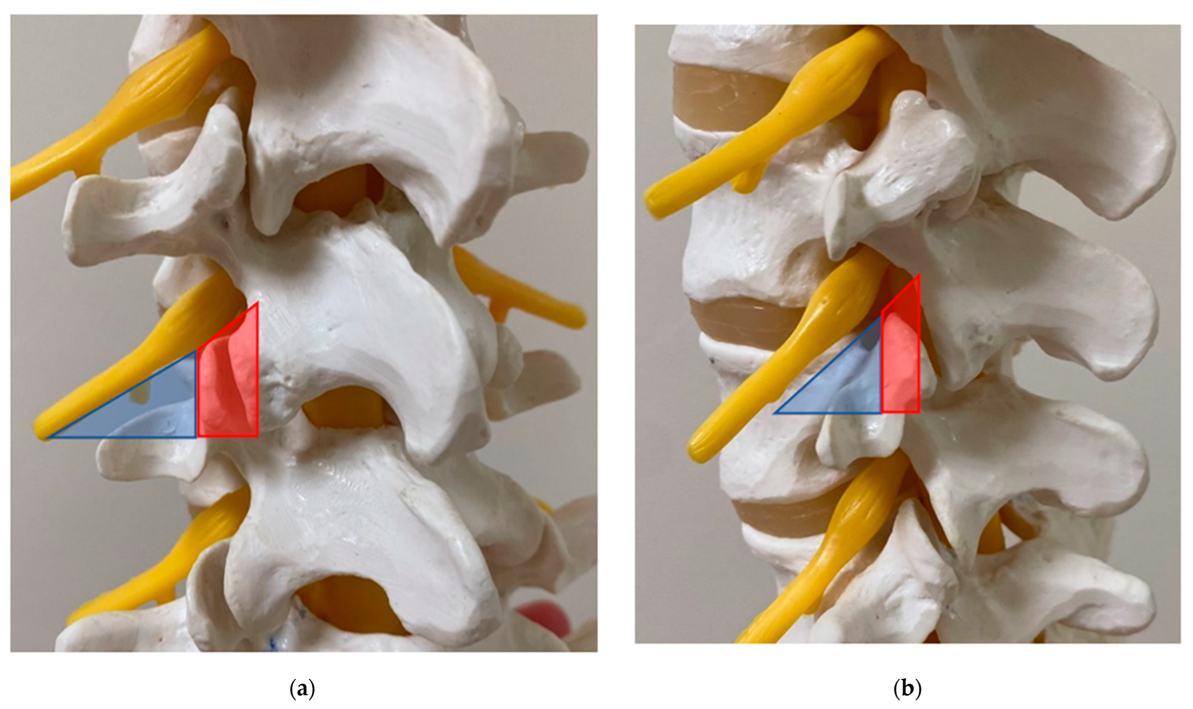
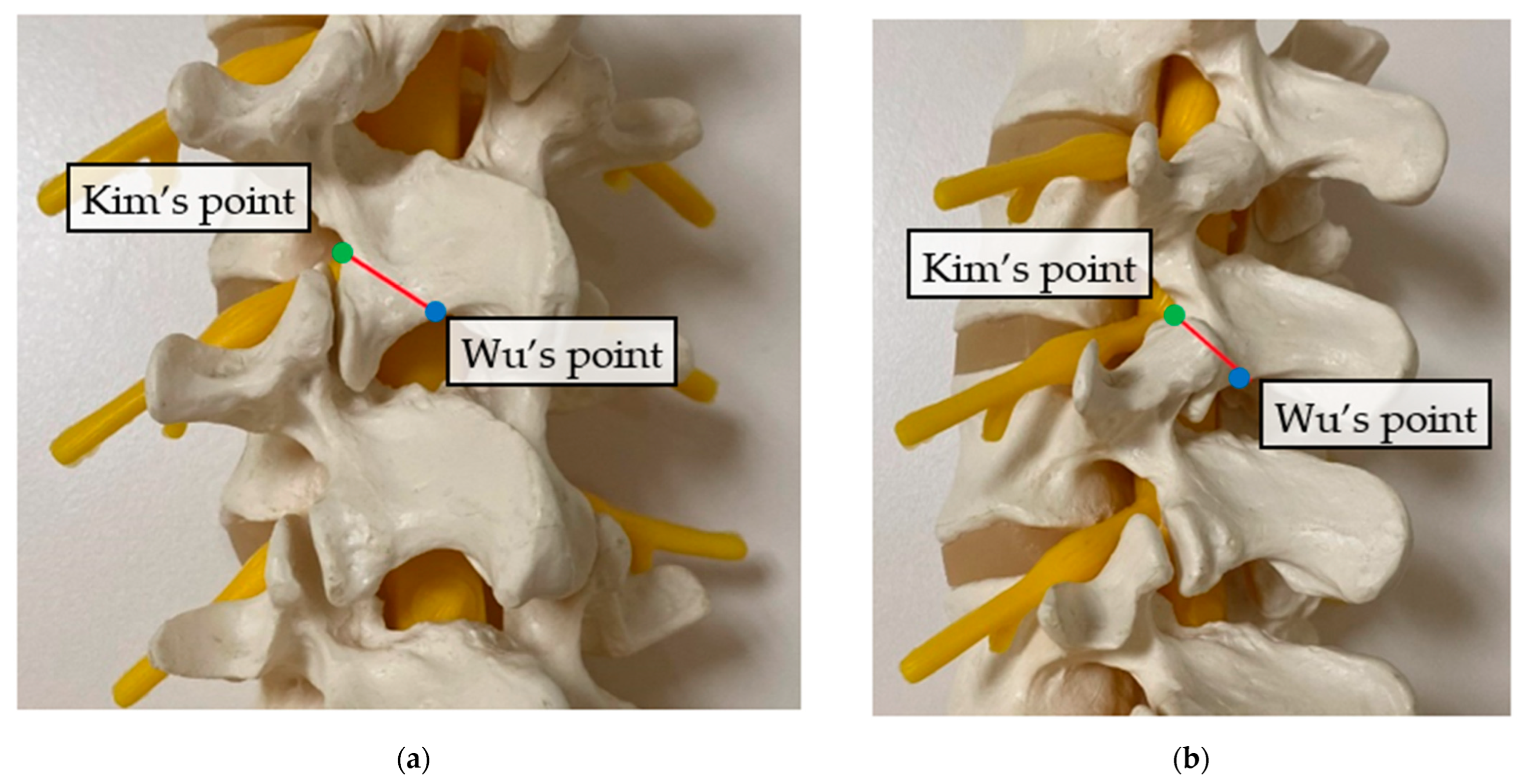
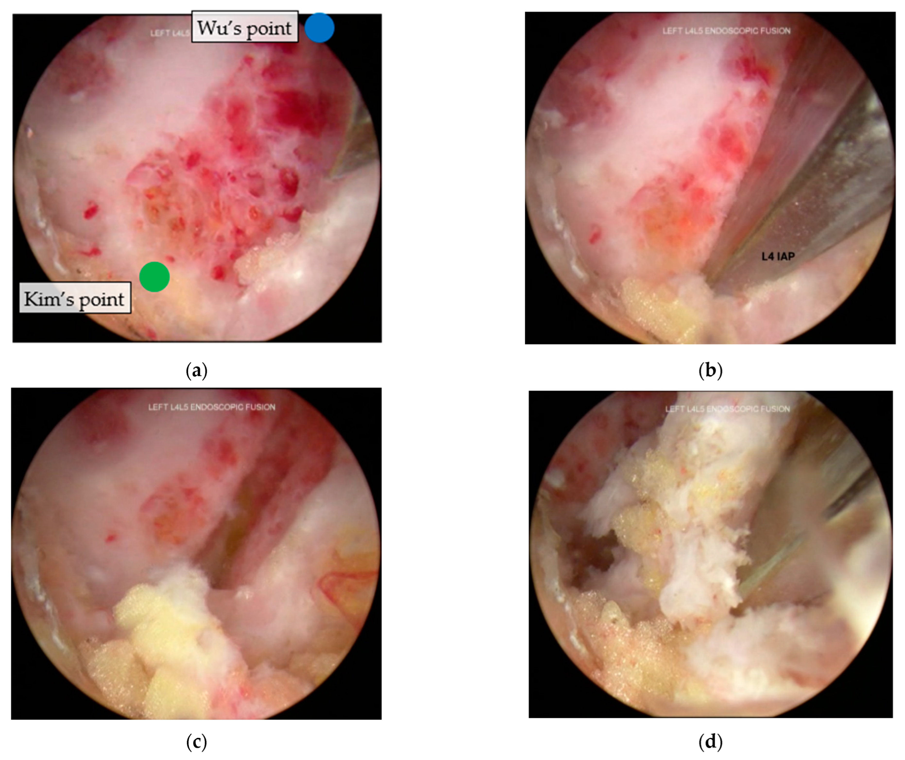
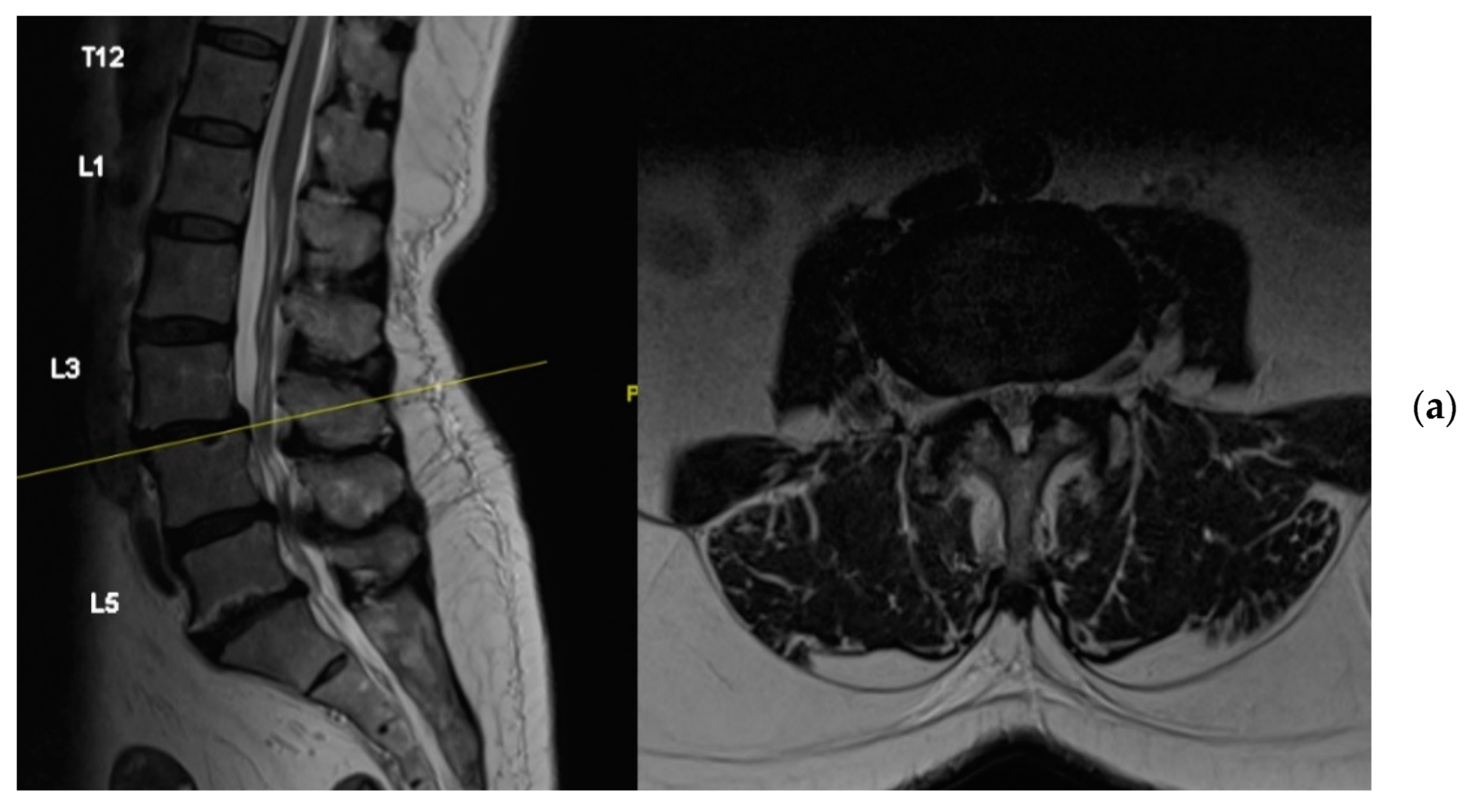
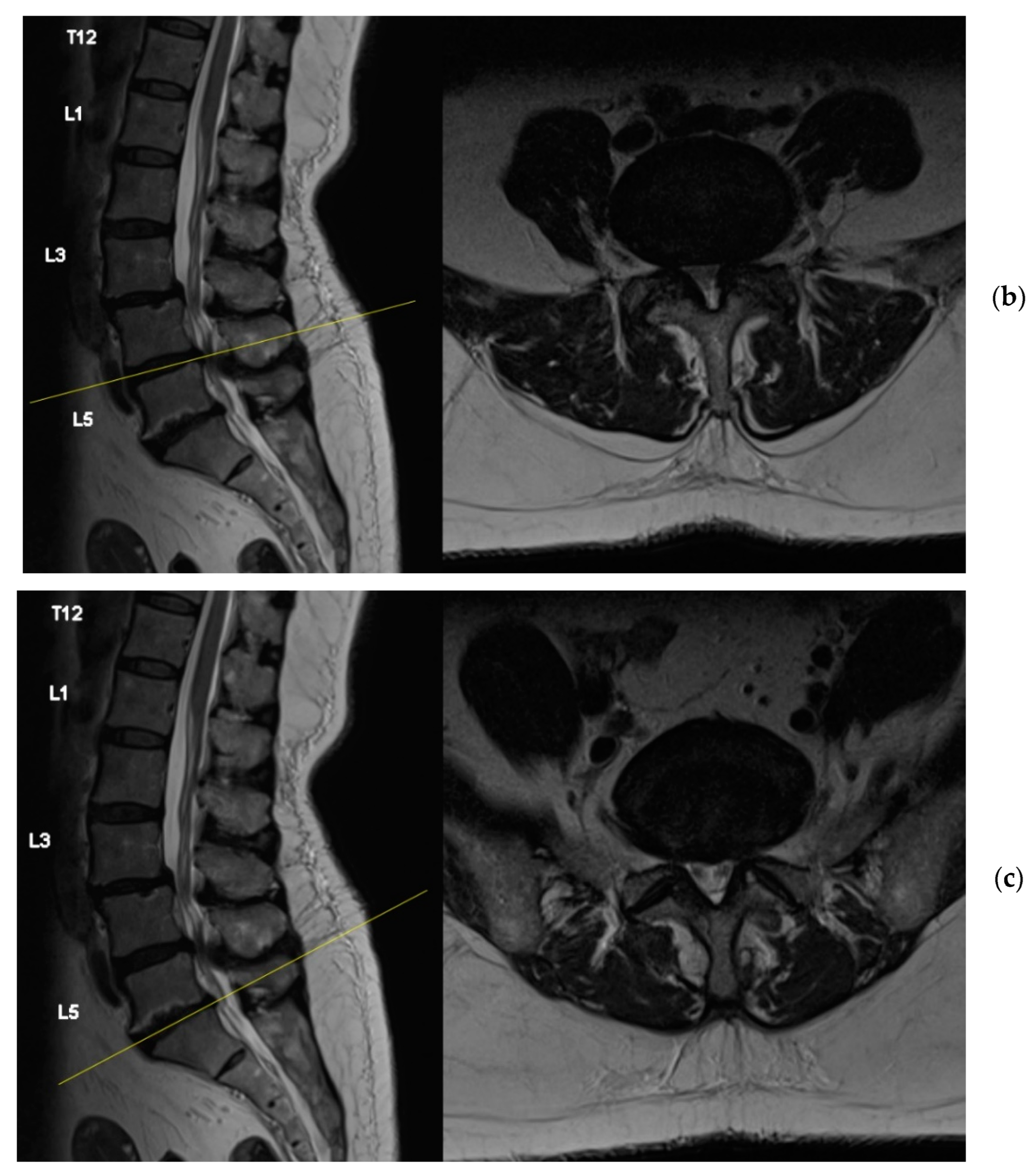
2. Surgical Anatomy
3. Surgical Technique
3.1. Anaesthesia and Positioning
3.2. Equipment
3.3. Skin Incision and Docking
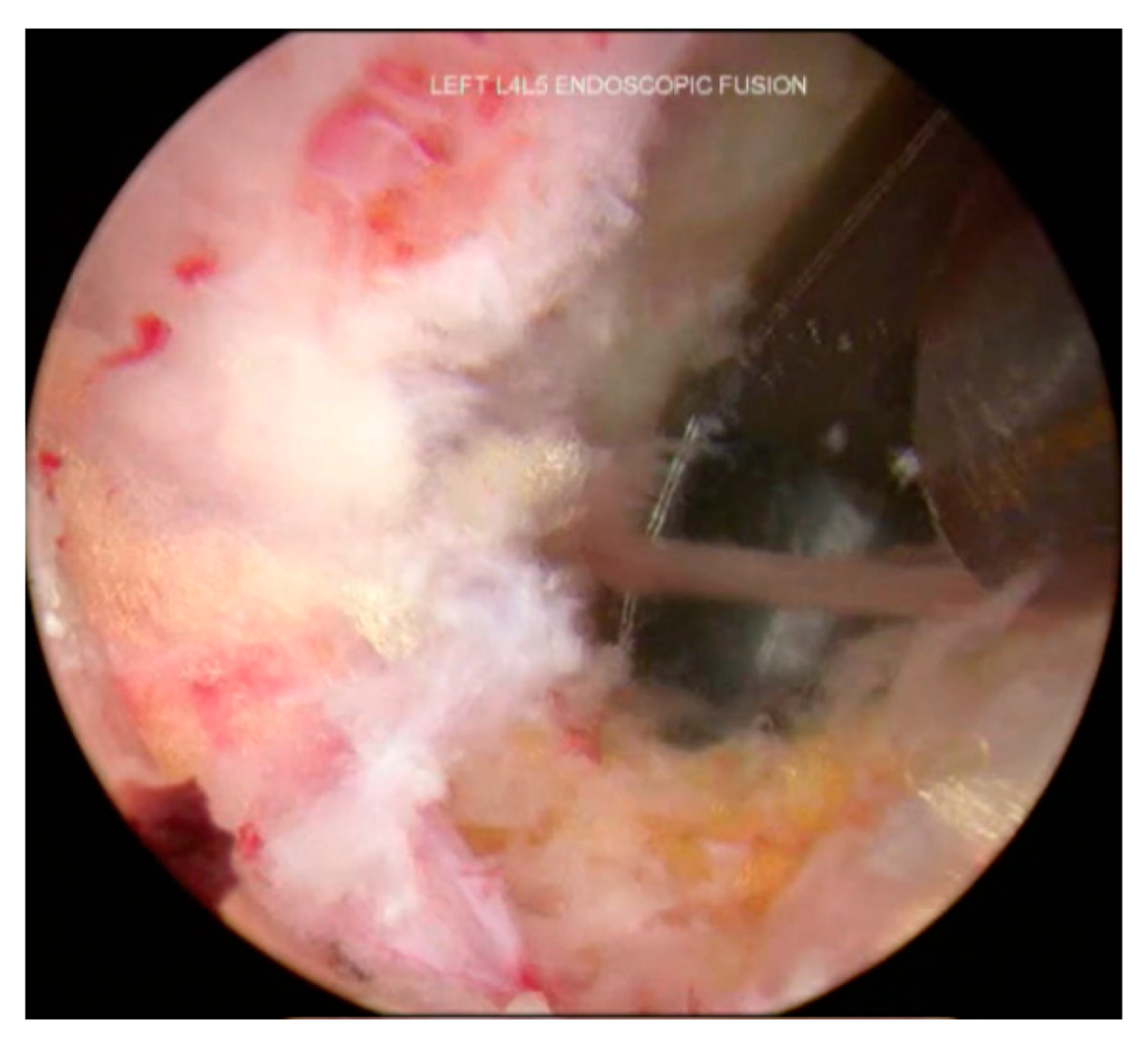
3.4. Inferior Articular Process Facetectomy
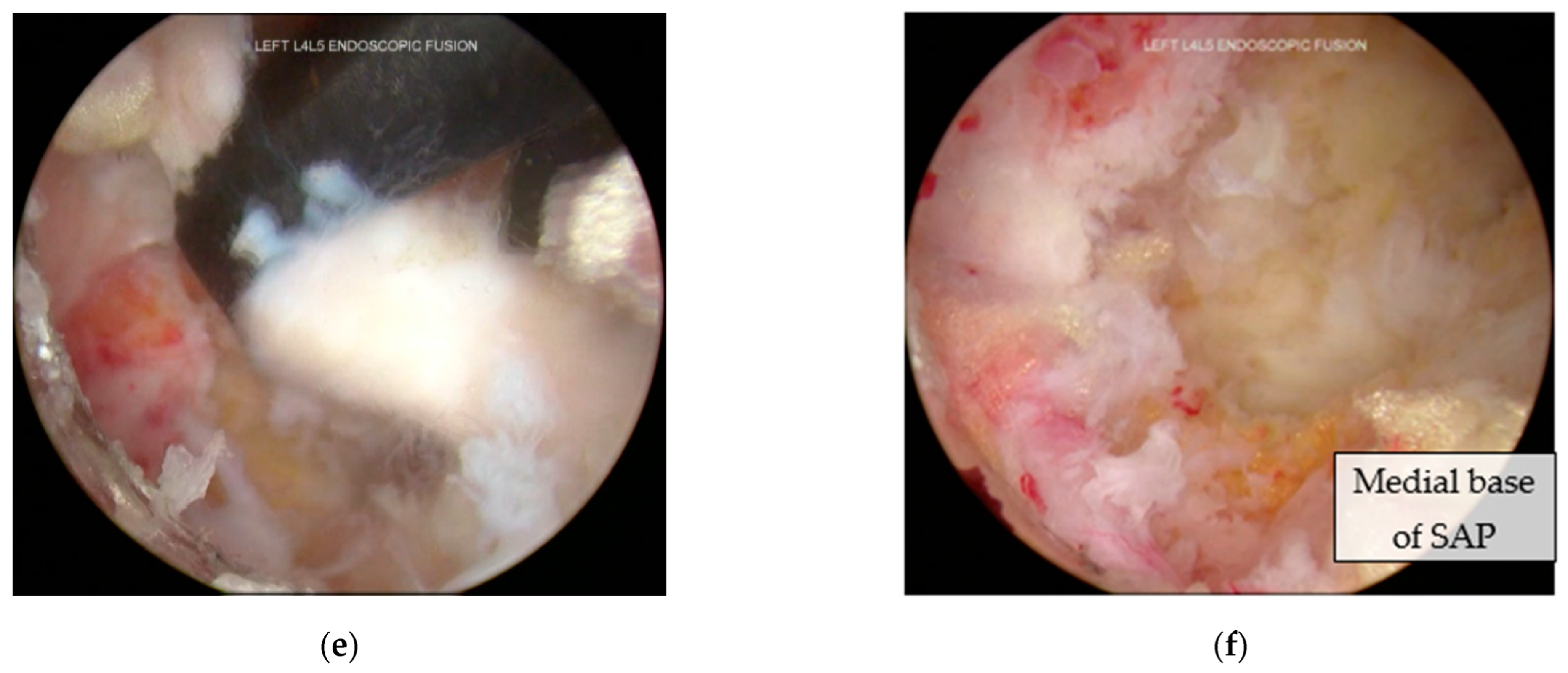
3.5. Superior Articular Process Facetectomy
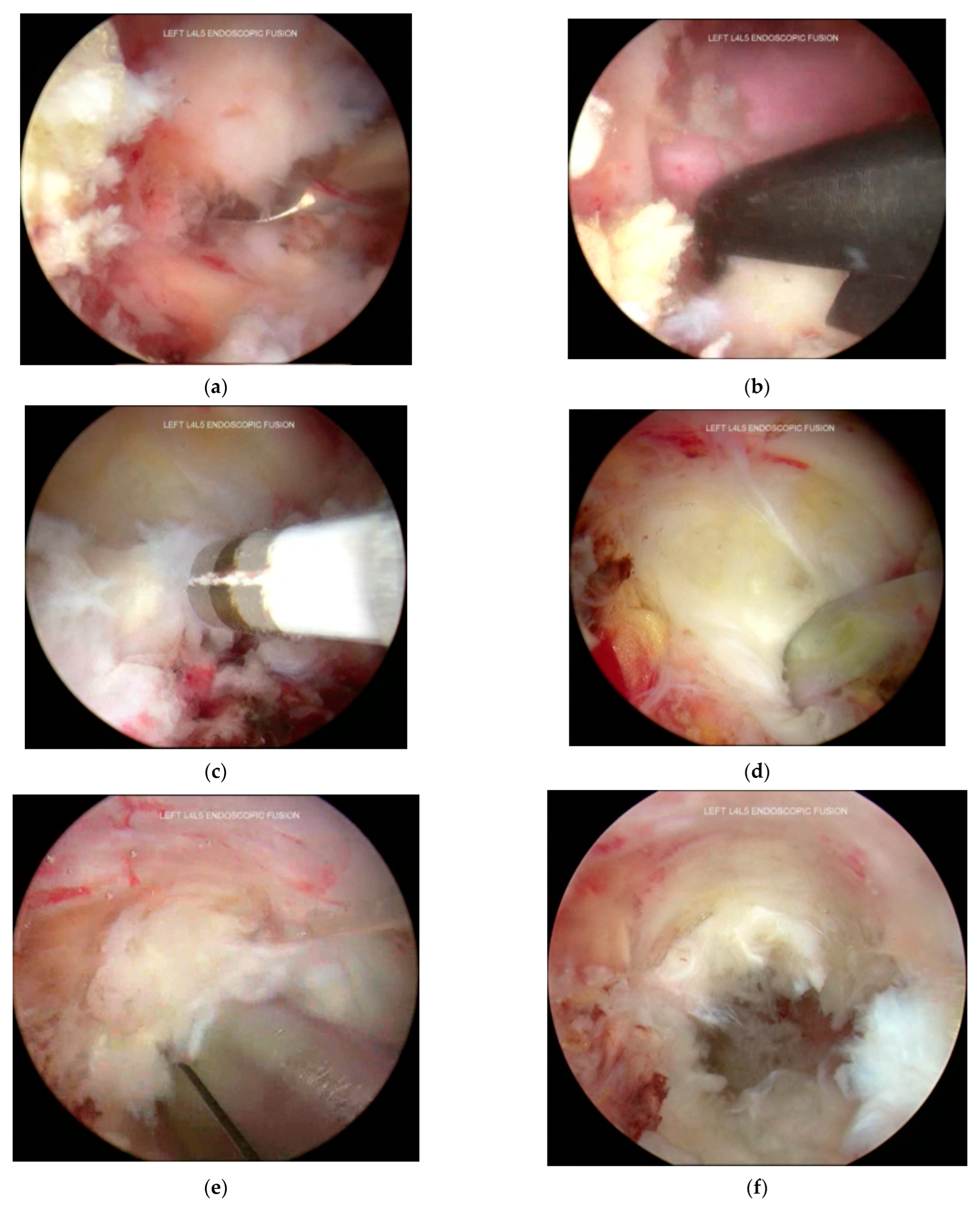
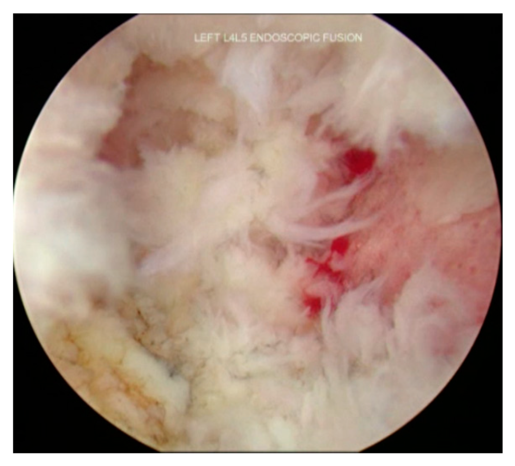
3.6. Decompression and Discectomy
3.7. Endplate Preparation
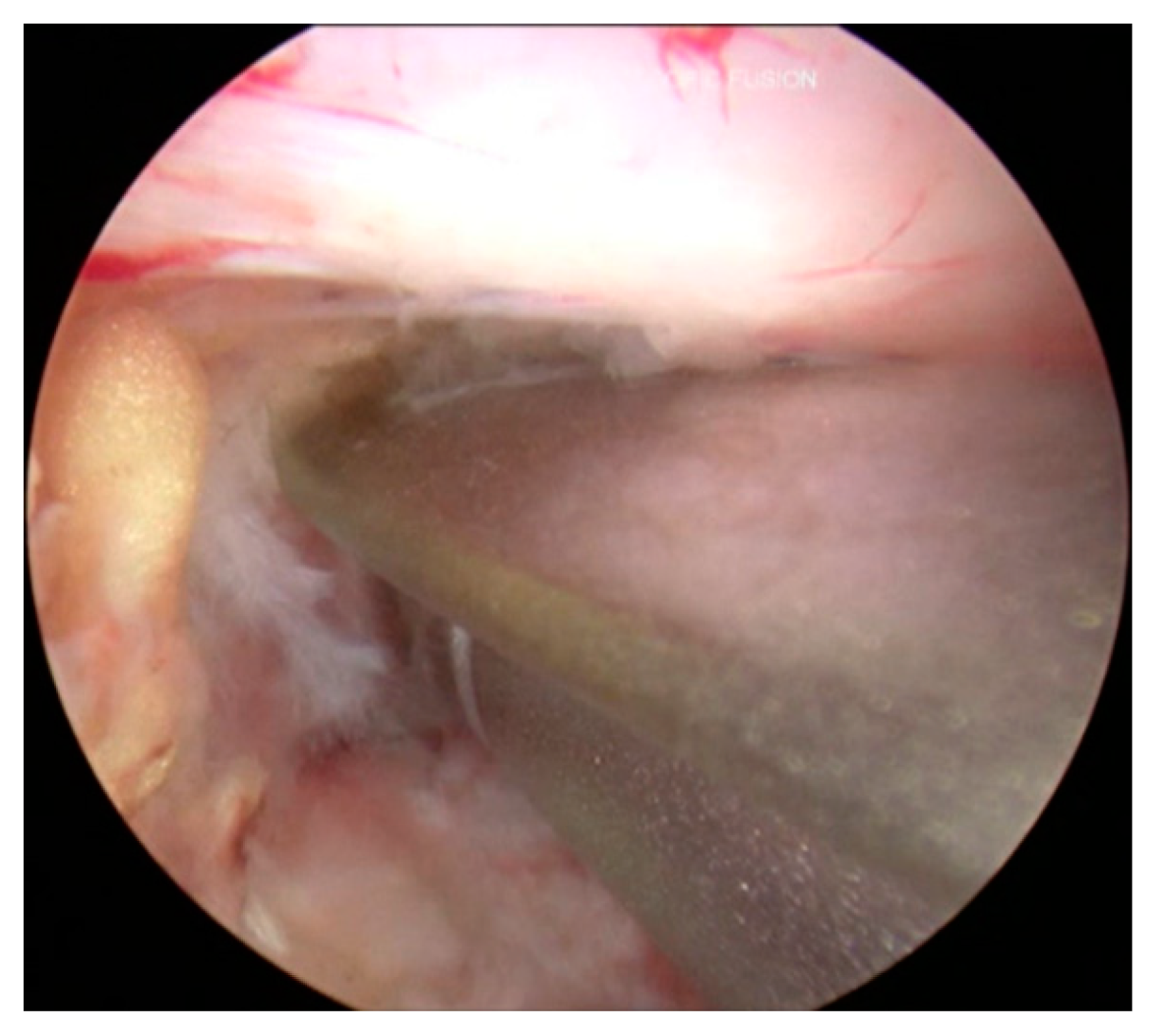
3.8. Cage Insertion with Retractors
3.9. Percutaneous Posterior Instrumentation under Fluoroscopic Guidance
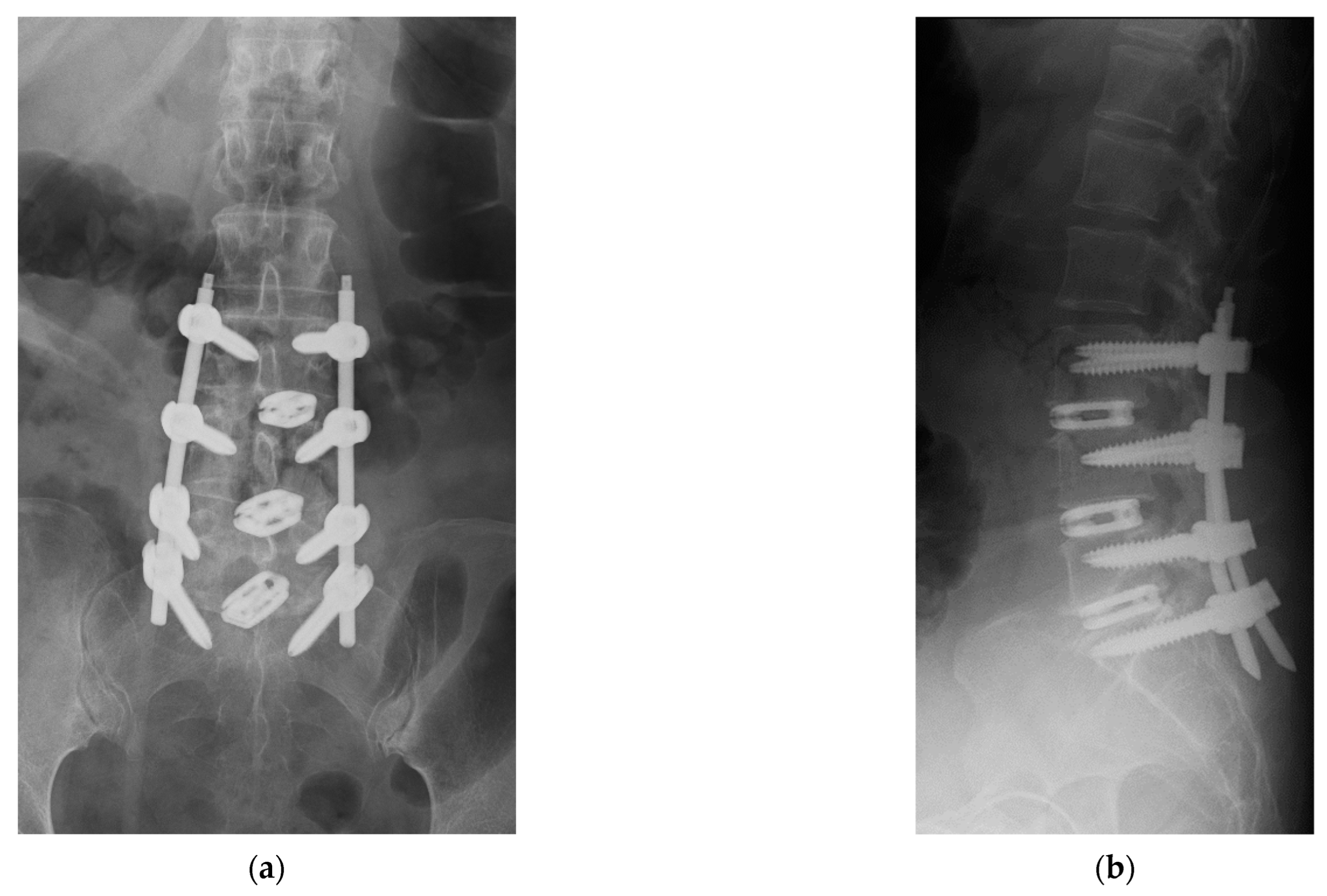
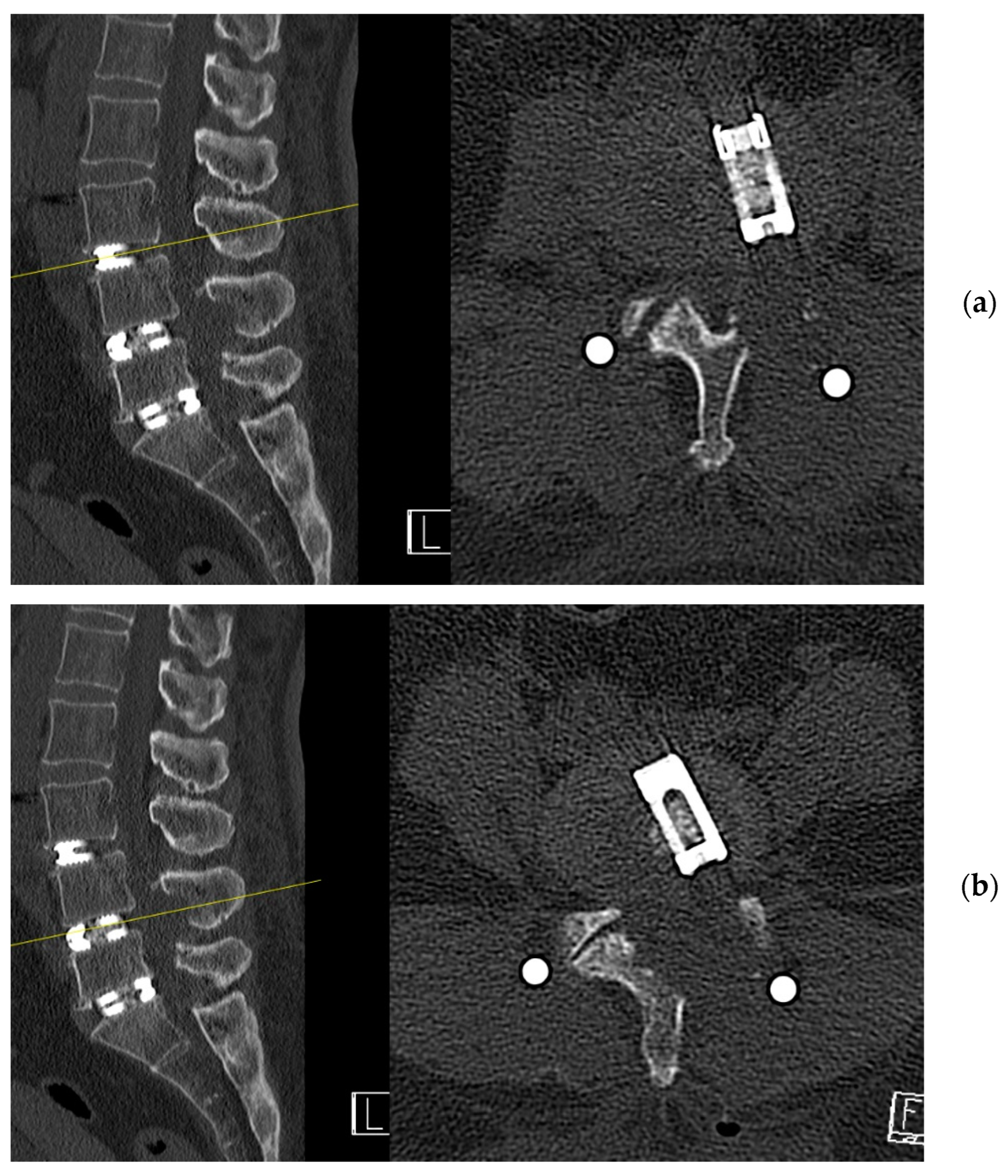
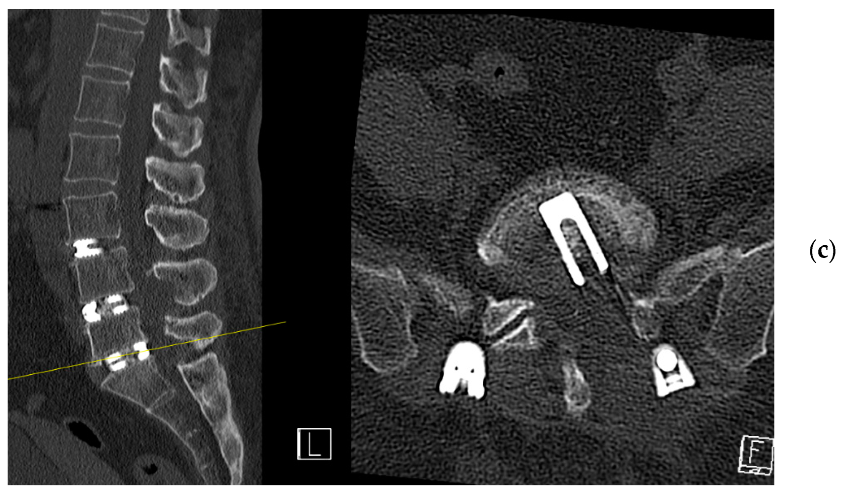
4. Case Example
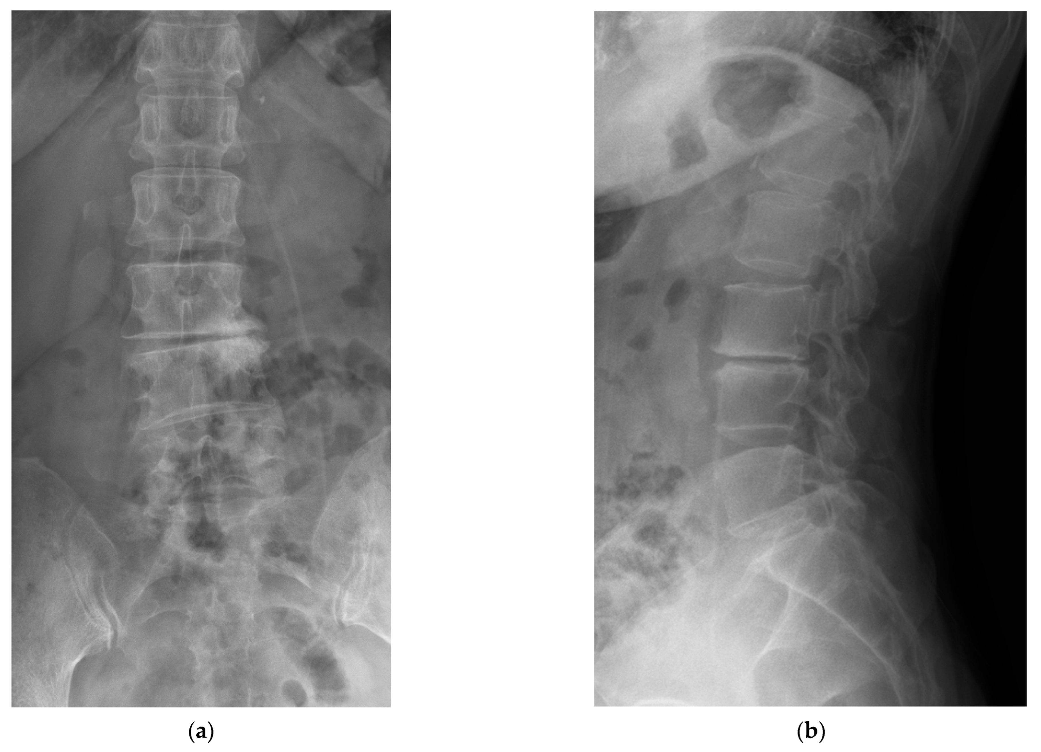
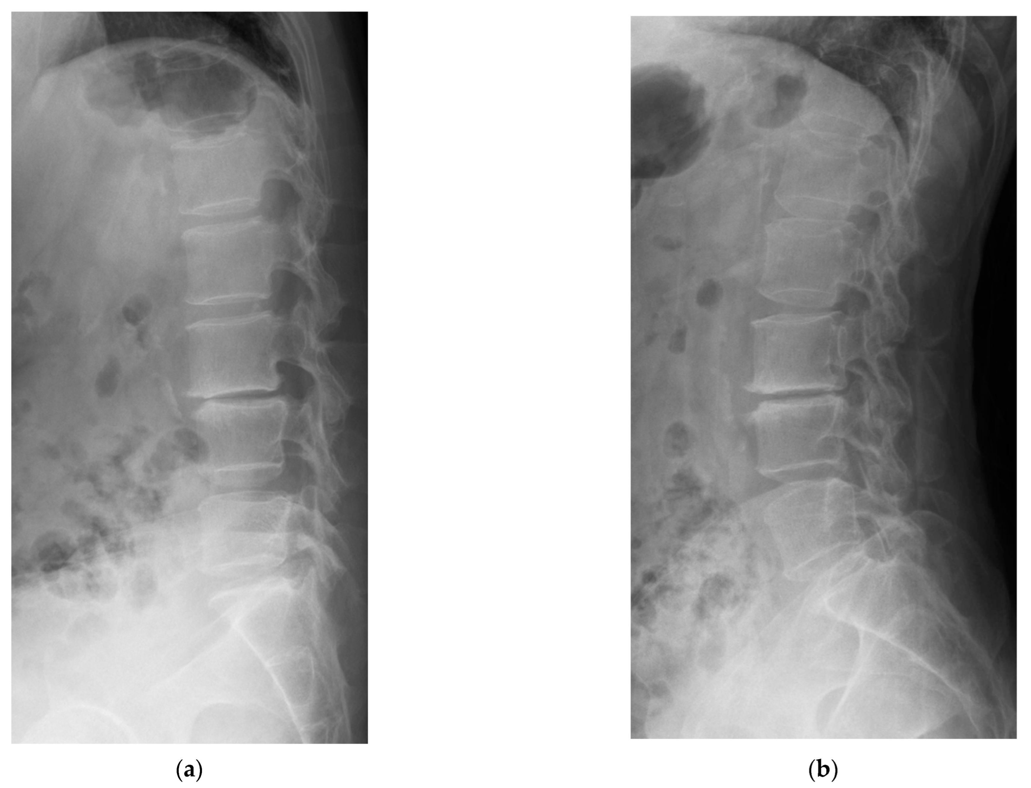
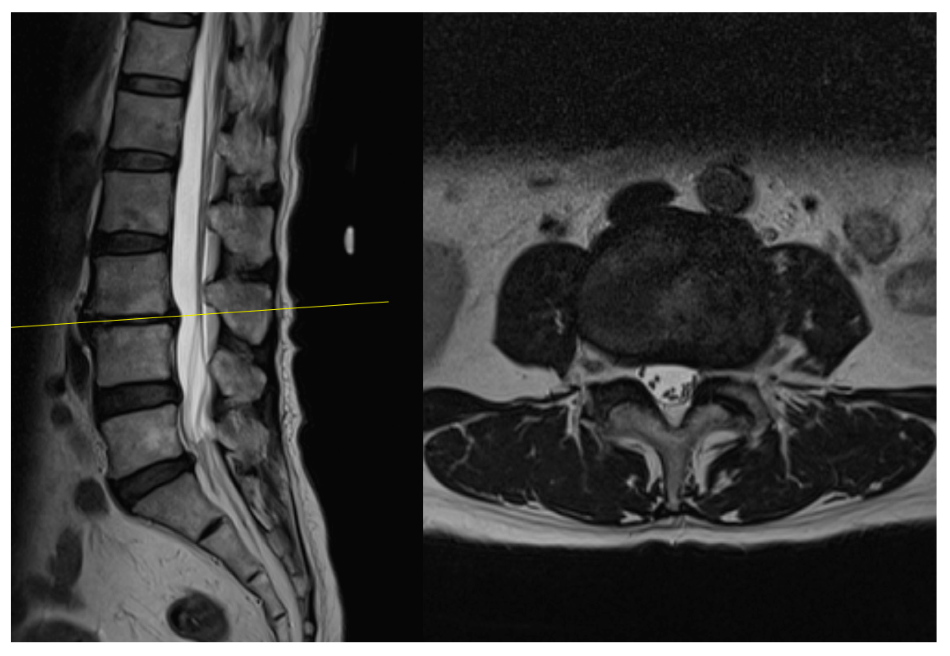
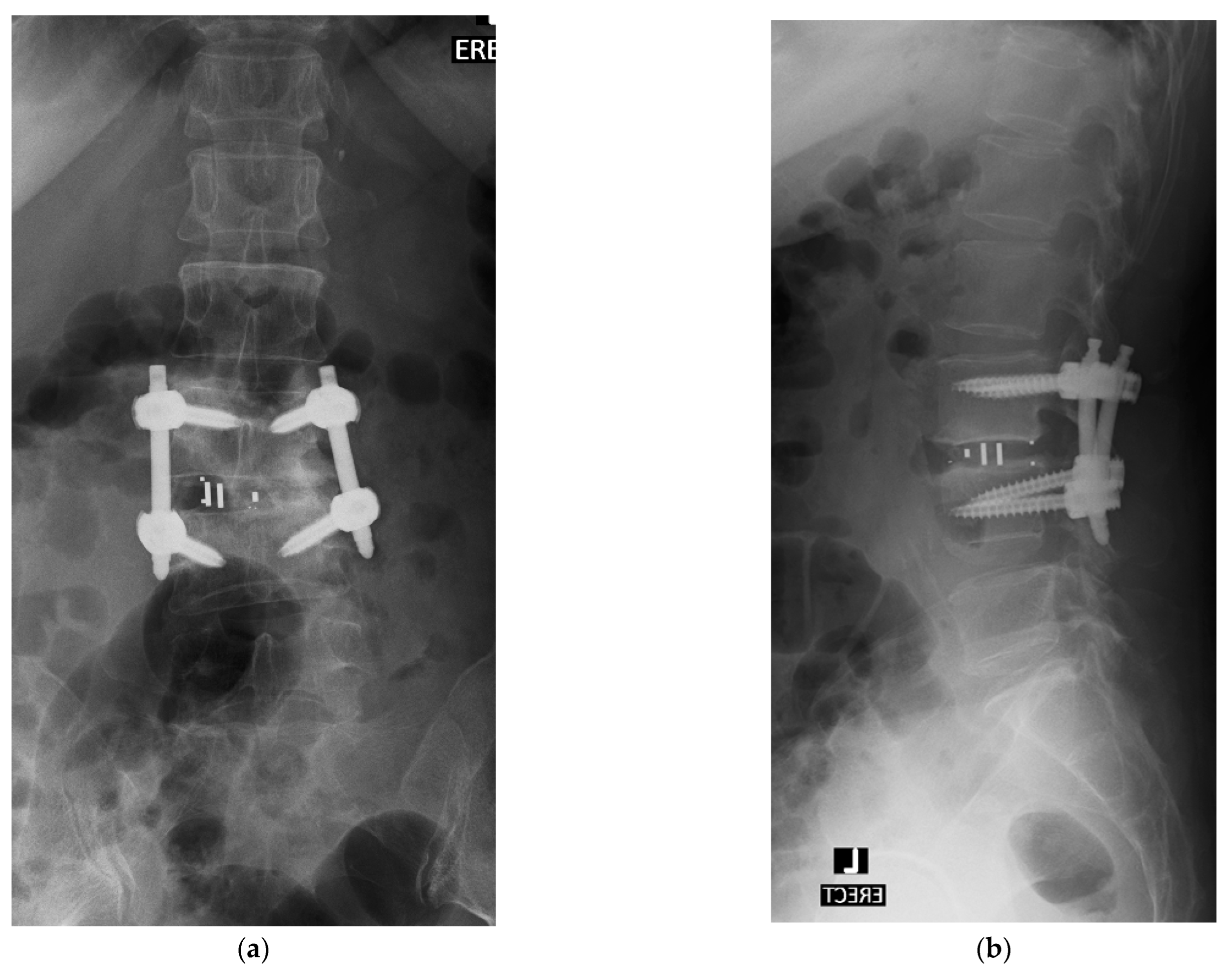
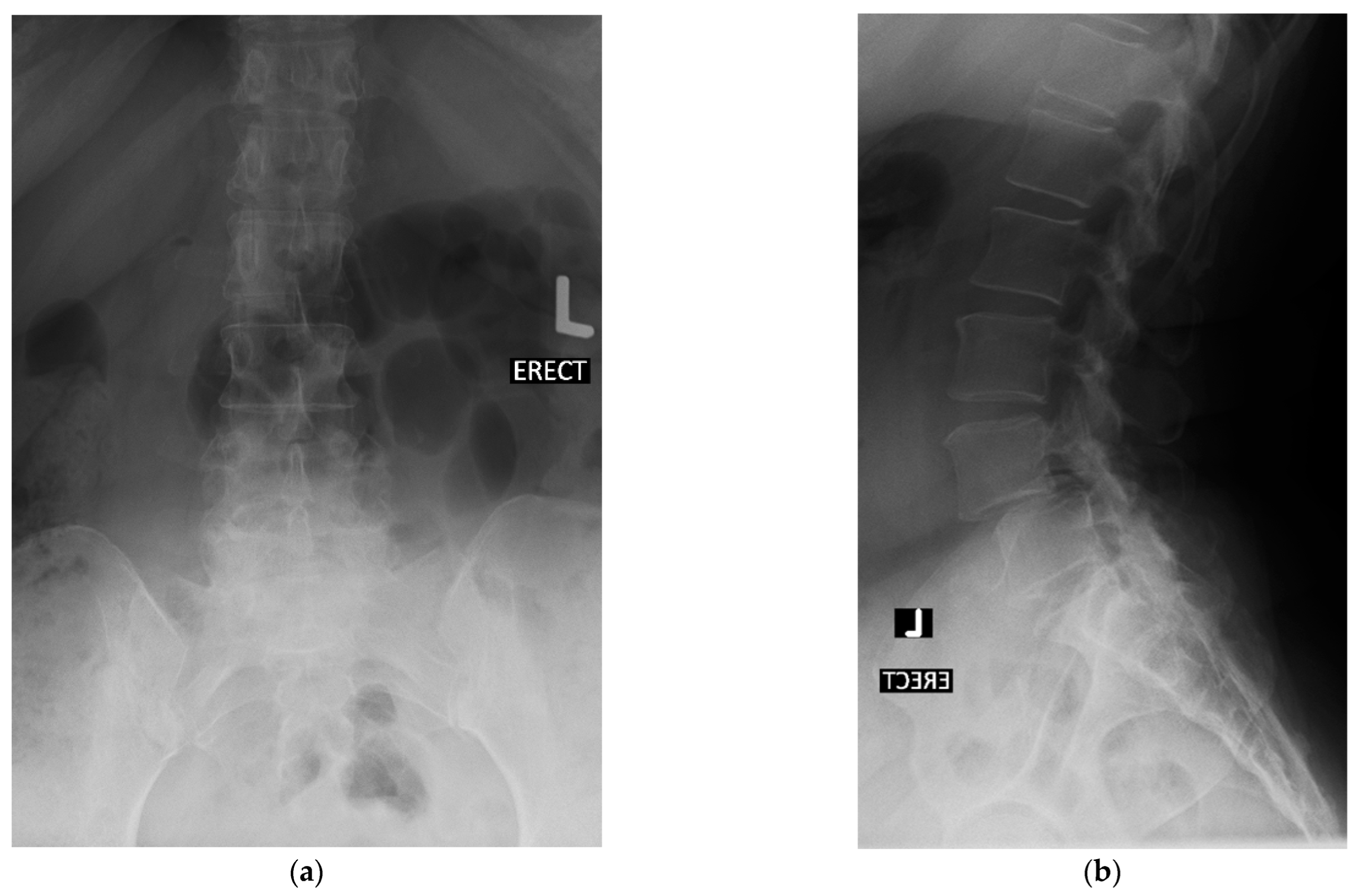
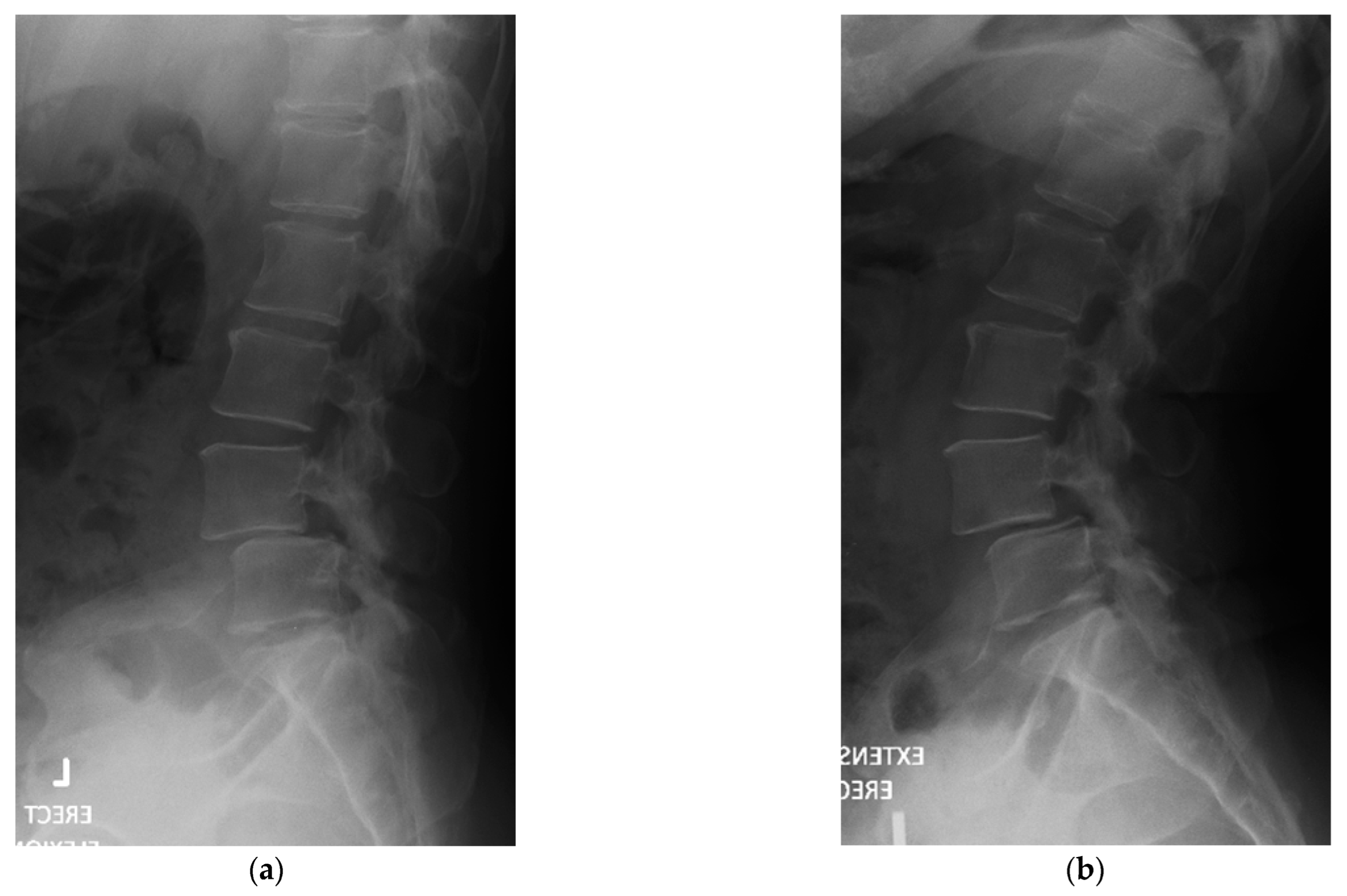
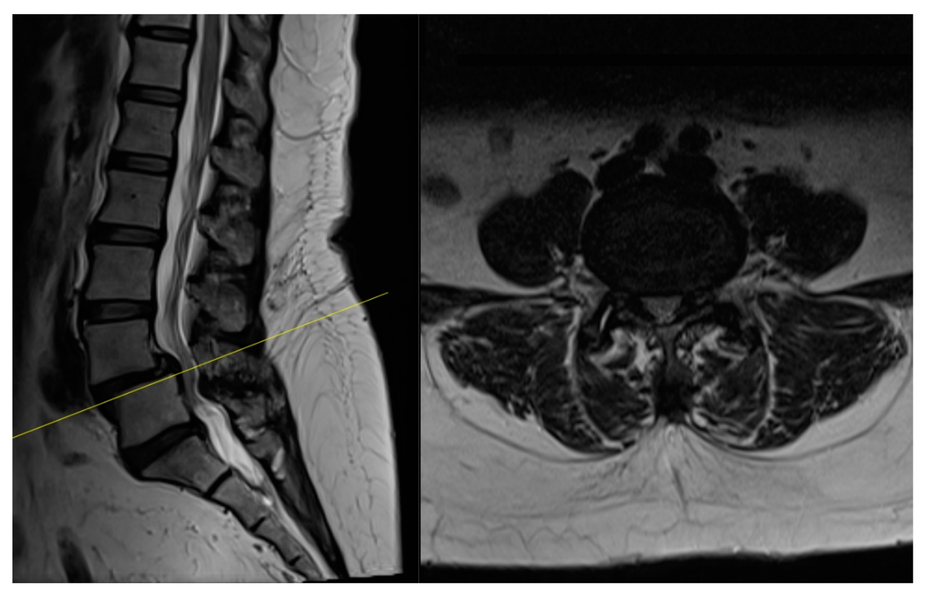
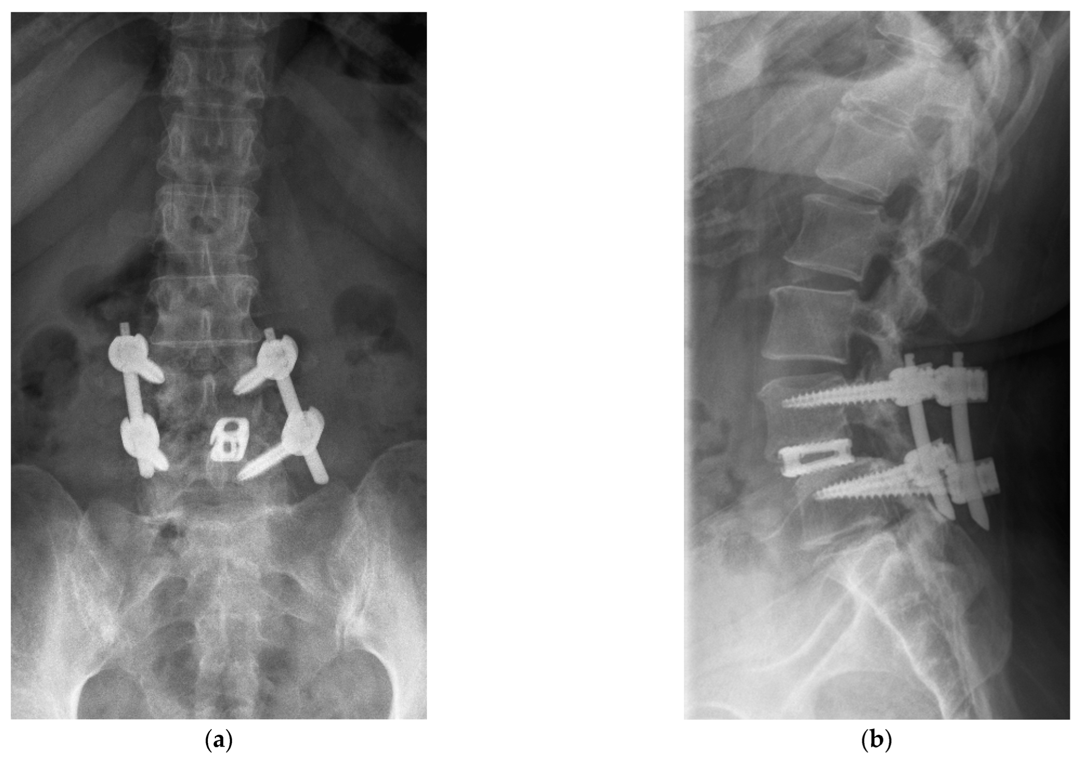
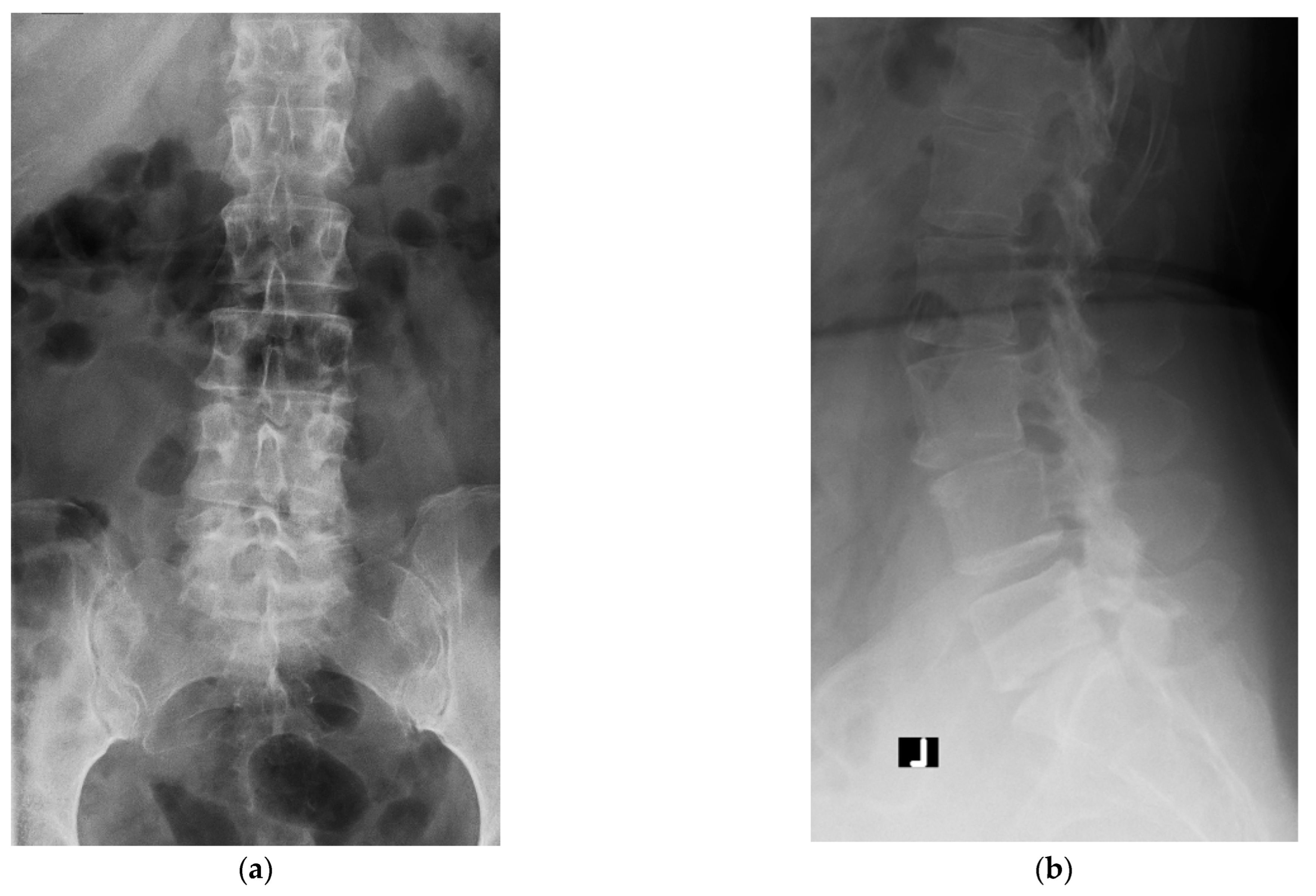
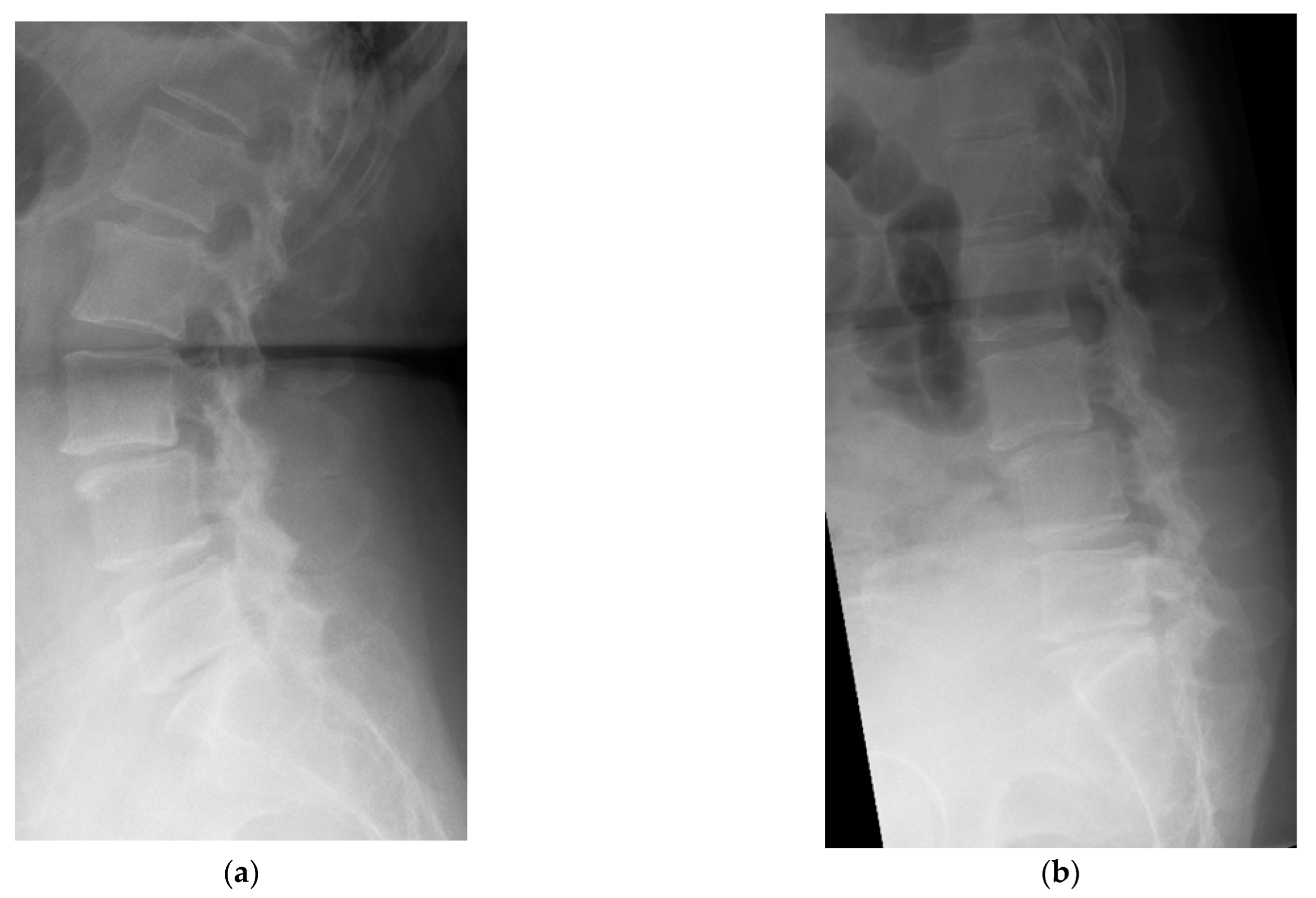
4.1. Case 1: Madam M
4.2. Case 2: Madam R
4.3. Case 3: Madam M
5. Discussion
6. Conclusions
Author Contributions
Funding
Informed Consent Statement
Data Availability Statement
Acknowledgments
Conflicts of Interest
References
- Derman, P.B.; Albert, T.J. Interbody fusion techniques in the surgical management of degenerative lumbar spondylolisthesis. Curr. Rev. Musculoskelet. Med. 2017, 10, 530–538. [Google Scholar] [CrossRef] [PubMed]
- Fritzell, P.; Hägg, O.; Wessberg, P.; Nordwall, A.; Swedish Lumbar Spine Study Group. 2001 Volvo Award Winner in Clinical Studies: Lumbar fusion versus nonsurgical treatment for chronic low back pain: A multicenter randomized controlled trial from the Swedish Lumbar Spine Study Group. Spine 2001, 26, 2521–2532. [Google Scholar] [CrossRef] [PubMed]
- Harms, J. Dorsale repositions spondylodese bei lumbalen spondylolisthesis. Oper. Orthopädie Traumatol. 1999, 11, 79. [Google Scholar] [CrossRef] [PubMed]
- Hilibrand, A.S.; Robbins, M. Adjacent segment degeneration and adjacent segment disease: The consequences of spinal fusion? Spine J. 2004, 4, S190–S194. [Google Scholar] [CrossRef] [PubMed]
- Yee, T.J.; Terman, S.W.; La Marca, F.; Park, P. Comparison of adjacent segment disease after minimally invasive or open transforaminal lumbar interbody fusion. J. Clin. Neurosci. 2014, 21, 1796–1801. [Google Scholar] [CrossRef] [PubMed]
- Foley, K.T. Advances in minimally invasive spine surgery. Clin. Neurosurg. 2002, 49, 499–517. [Google Scholar] [PubMed]
- Khan, N.R.; Clark, A.J.; Lee, S.L.; Venable, G.T.; Rossi, N.B.; Foley, K.T. Surgical outcomes for minimally invasive vs open transforaminal lumbar interbody fusion: An updated systematic review and meta-analysis. Neurosurgery 2015, 77, 847–874. [Google Scholar] [CrossRef] [PubMed]
- Ishihama, Y.; Morimoto, M.; Tezuka, F.; Yamashita, K.; Manabe, H.; Sugiura, K.; Takeuchi, M.; Takata, Y.; Sakai, T.; Maeda, T.; et al. Full-endoscopic trans-Kambin triangle lumbar interbody fusion: Surgical technique and nomenclature. J. Neurol. Surg. Part A Cent. Eur. Neurosurg. 2021, 6, S123–S129. [Google Scholar] [CrossRef] [PubMed]
- Kim, H.S.; Wu, P.H.; Sairyo, K.; Jang, I.T. A Narrative Review of Uniportal Endoscopic Lumbar Interbody Fusion: Comparison of Uniportal Facet-Preserving Trans-Kambin Endoscopic Fusion and Uniportal Facet-Sacrificing Posterolateral Transforaminal Lumbar Interbody Fusion. Int. J. Spine Surg. 2021, 15 (Suppl. S3), S72–S83. [Google Scholar] [CrossRef] [PubMed]
- Wu, P.H.; Kim, H.S.; Choi, D.J.; Gamaliel, Y.H. Overview of tips in overcoming learning curve in uniportal and biportal endoscopic spine surgery. J. Minim. Invasive Spine Surg. Tech. 2021, 6 (Suppl. S1), S84–S96. [Google Scholar] [CrossRef]
- Kambin, P.; Brager, M.D. Percutaneous posterolateral discectomy. Anatomy and mechanism. Clin. Orthop. Relat. Res. 1987, 223, 145–154. [Google Scholar] [CrossRef]
- Kim, H.S.; Wu, P.H.; An, J.W.; Lee, Y.J.; Lee, J.H.; Kim, M.H.; Lee, I.; Park, J.S.; Lee, J.H.; Park, J.H.; et al. Evaluation of two methods (inside-out/outside-in) inferior articular process resection for uniportal full endoscopic posterolateral transforaminal lumbar interbody fusion. Brain Sci. 2021, 11, 1169. [Google Scholar] [CrossRef]
- Hsu, H.T.; Chang, S.J.; Yang, S.S.; Chai, C.L. Learning curve of full-endoscopic lumbar discectomy. Eur. Spine J. 2013, 22, 727–733. [Google Scholar] [CrossRef]
- Kong, F.; Zhou, Q.; Qiao, Y.; Wang, W.; Zhang, C.; Pan, Q.; Zhu, H. Comparison of unilateral biportal endoscopic transforaminal lumbar interbody fusion versus minimally invasive tubular transforaminal lumbar interbody fusion for lumbar degenerative disease. Chin. J. Reparative Reconstr. Surg. 2022, 36, 592–599. [Google Scholar]
- Park, M.K.; Park, S.A.; Son, S.K.; Park, W.W.; Choi, S.H. Clinical and radiological outcomes of unilateral biportal endoscopic lumbar interbody fusion (ULIF) compared with conventional posterior lumbar interbody fusion (PLIF): 1-year follow-up. Neurosurg. Rev. 2019, 42, 753–761. [Google Scholar] [CrossRef] [PubMed]


Publisher’s Note: MDPI stays neutral with regard to jurisdictional claims in published maps and institutional affiliations. |
© 2022 by the authors. Licensee MDPI, Basel, Switzerland. This article is an open access article distributed under the terms and conditions of the Creative Commons Attribution (CC BY) license (https://creativecommons.org/licenses/by/4.0/).
Share and Cite
Lau, E.T.-C.; Wu, P.H. Technical Note on Unilateral Biportal Lumbar Endoscopic Interbody Fusion. Surg. Tech. Dev. 2022, 11, 71-89. https://doi.org/10.3390/std11020007
Lau ET-C, Wu PH. Technical Note on Unilateral Biportal Lumbar Endoscopic Interbody Fusion. Surgical Techniques Development. 2022; 11(2):71-89. https://doi.org/10.3390/std11020007
Chicago/Turabian StyleLau, Eugene Tze-Chun, and Pang Hung Wu. 2022. "Technical Note on Unilateral Biportal Lumbar Endoscopic Interbody Fusion" Surgical Techniques Development 11, no. 2: 71-89. https://doi.org/10.3390/std11020007