Article

Optimal Electric Vehicle Fleet Charging Management with a Frequency Regulation Service

1
LS2N, CNRS, École Centrale Nantes, Nantes Université, UMR 6004, 44321 Nantes, France
2
Renault Group Technocentre Guyancourt, 78288 Guyancourt, France
*
Author to whom correspondence should be addressed.
Current address: Envision Digital, 92400 Courbevoie, France.
World Electr. Veh. J. 2023, 14(6), 152; https://doi.org/10.3390/wevj14060152
Submission received: 13 April 2023 / Revised: 22 May 2023 / Accepted: 6 June 2023 / Published: 9 June 2023
(This article belongs to the Topic Electric Vehicles Energy Management)

Abstract

:
Electric vehicles are able to provide immediate power through the vehicle-to-grid function, and they can adjust their charging power level when in the grid-to-vehicle mode. This allows them to provide ancillary services such as frequency control. Their batteries differ from conventional energy storage systems in that the owner’s energy requirement constraint must be met when the vehicles participate in a frequency control system. An optimization problem was defined by considering both the owner satisfaction and frequency control performance. The main contribution of the proposed paper, compared to the literature, are (1) to keep the total available energy stored in the batteries connected to a charging station in an optimal region that favors the frequency regulation capability of the station and the proposed QoS and (2) to consider the optimal region bounded by the efficiency thresholds of the charger to allow for maximum regulation power. The problem is expressed as a multi-criteria optimization problem with time-dependent references. The paper presents an energy management strategy for frequency control, describes a concept of an optimal time-dependent state of charge for electric vehicle charging demands, and considers the power dependence of the electric vehicle charger efficiency. Finally, the simulation results are presented via Matlab/Simulink to prove the effectiveness of the proposed algorithm.

Graphical Abstract

1. Introduction

Electric vehicles (EVs) can help improve the quality of the power grid by participating in ancillary services such as valley filling, reactive power compensations, voltage drops, and frequency regulation. The massive integration of vehicle-to-grid (V2G) functionality in the EVs’ charger will make EVs flexible with connected energy resources. In addition, the fast response of EVs and the high-power density of lithium batteries make EVs suitable for frequency regulation [1,2,3].
The problem of charging EVs with a frequency control service has been the subject of several studies. The EV charging problem, which considers frequency regulation with a control theory has been, for example, addressed in [4,5,6,7,8,9,10,11]. Others, such as [1,12,13,14,15,16] use the optimization approach to find the optimal charging power. Other methods based on fuzzy logic, deep reinforcement learning, and priority models have been used in [17,18,19,20].
To solve the problem of frequency-controlled EV charging, several considerations must be taken into account. The objective of keeping the operational capacity limit in the optimal region—where the up-regulation power is at the maximum and the down-regulation power is also at the maximum—is considered in [14,16], whereas [13,15] did not consider this aspect. Furthermore, refs. [14,15] considered a constant value for the upward power control, as well as for the downward power control of the EV. Therefore, they did not take into account the dependence of the regulation capacity on the up and down state in the charge of the battery (SoC). In addition, addressing the expectations of EV owners’ is a major challenge in this area. In [13,14,16,21], the user satisfaction was taken into account, while this point was completely ignored in [22,23]. Ignoring this aspect could discourage EV owners from participating in ancillary services.
Many studies have considered a large number of EVs participating in ancillary services. In [14], the study was conducted with a large number of EVs, equal to 100,000, while [1] assumes the use of 1000 EVs in the simulation, and [6] sets the total number of EVs involved in the simulation of the frequency control algorithm to 500. The focus of this paper is to investigate the feasibility of providing a frequency control service with a small number of EVs. Therefore, in all simulations, the maximum number of EVs is 20. In addition, refs. [14,16] used an assigned symmetric disturbance signal that simplified the problem of achieving the SoC objective and maintained the problem of the control capacity. Moreover, refs. [6,14] considered an equally likely distribution of the number of EVs in each SoC category (low, medium, and high).
Most of the research using the [14,16] optimization approach set a strict equality constraint in their optimization models. Equalities are harder to satisfy exactly, and they are not compatible with all solvers. One modeling trick is to reformulate each equality as two inequalities, but this increases the number of constraints and thus the size of the problem [12]. Accordingly, only inequality constraints are used in the proposed optimization model.
In control theory, the perturbation is distributed uniformly among the EVs. In the case of a small disturbance and a high number of controlled EVs, each EV with small power fluctuations will participate in frequency regulation to maintain the SoC without considering the poor efficiency of the charger in low-power regions. However, according to [22], the charger is designed to operate more efficiently closer to the maximum power levels. In the same context, refs. [13,22] study the effect of charger efficiency on the tracking accuracy of the spurious signal and assume that, without considering the dependence of charger efficiency on power, the tracking error increases.
Charger efficiency constraint: To our best knowledge, none of the existing work takes into account the dependence of charger efficiency on power. Almost all studies assume a constant charger efficiency in the range [ 0.8 , 1 ] . Some of them do not use a discharge efficiency or assume a perfect charger with unit efficiency.
In an EV charging management, the available energy provides information about the accumulation of energy to charge the EV. Thus, the energy provides a kind of future energy-usage possibility, such as the maximum charging and discharging rates, as well as the energy remaining to reach full capacity or full discharge. However, energy cannot convey long-term knowledge about the state of the EV or its history, but it does provide short-term information. Combining two heterogeneous physical quantities, such as energy and power, in the same objective function provides a global vision of the charging management of the EV fleet in both the long and short term, as well as in its past, present, and future. This model allows solving the optimization planning problem as a moment problem. Thus, the scheduling problem, whose solution is hard in terms of computational time and memory consumption, will be replaced by an instantaneous dispatching problem, whose solution is simple and fast. The added value in this model allows us to reduce the execution time; thus, we can tackle real-time problems such as frequency regulation for the coordinated charging of electric vehicles, as well as reducing the time step as much as the desired accuracy.
The main contribution of this paper, compared to the previously investigated literature, is to propose an optimal EV fleet charging management system that takes into account the power dependence of charger efficiencies, and which extends our previous work [20] (which is significantly improved upon) to the case of bidirectional charging. In detail, the contributions highlighting the proposed strategy are to
  • Maximize the regulatory reserve by using an EV charging algorithm based on preventive actions, replacing the planning problem with one on the fly;
  • Avoid the use of hard constraints, as well as reducing the number of decision variables and the number of constraints to reduce computation time and memory usage;
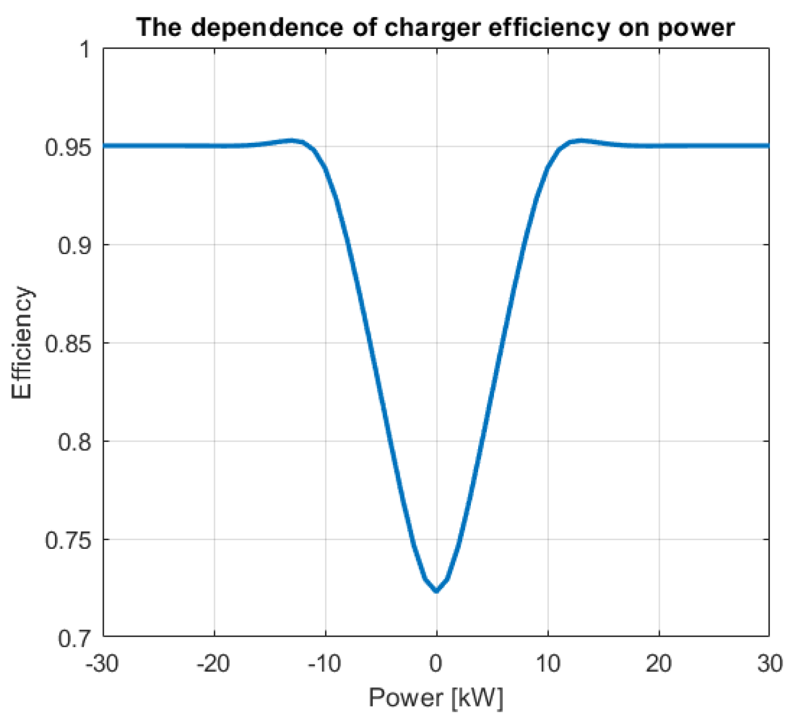
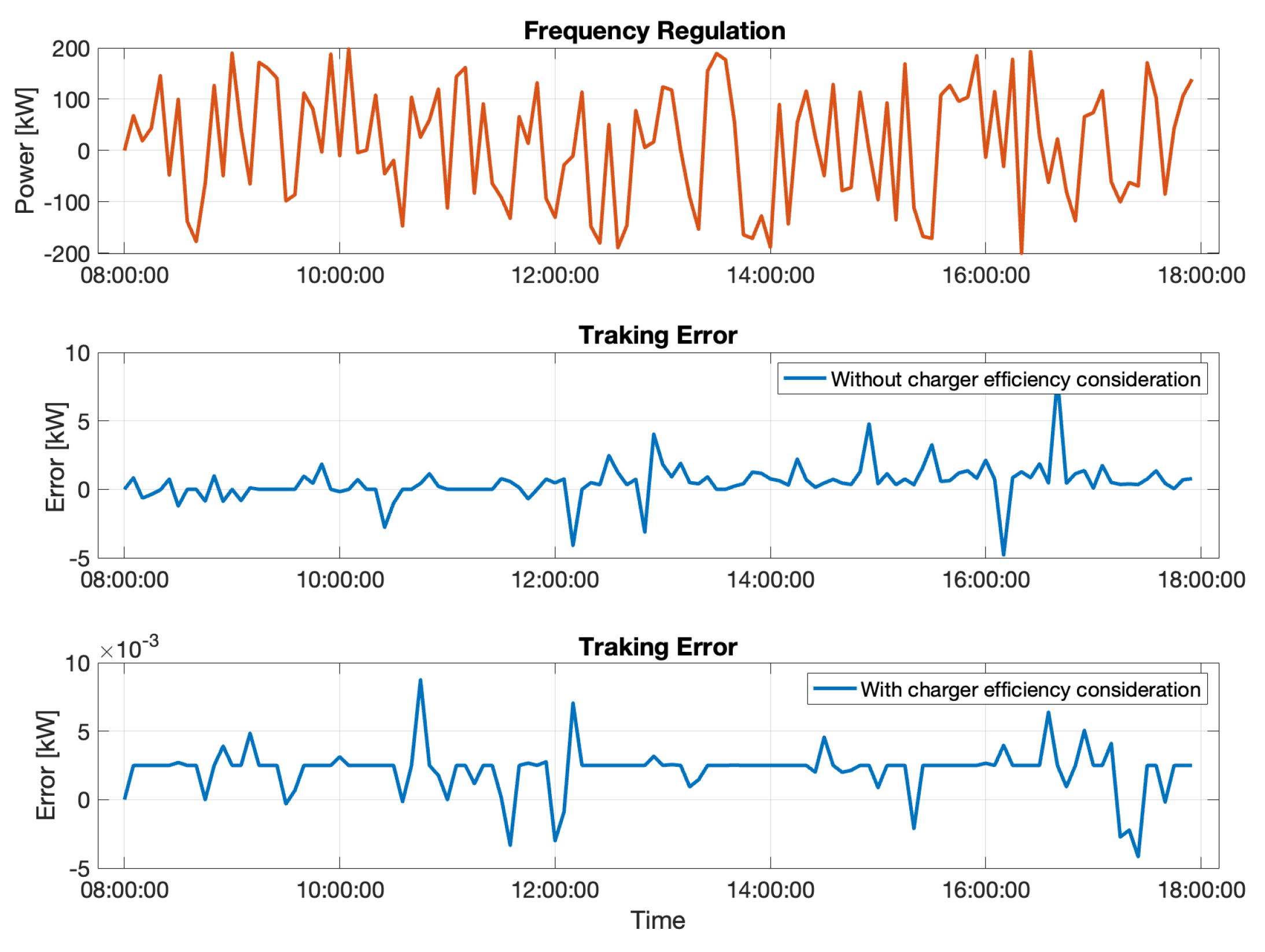
  • Take into account the efficiency of the charger and its dependence on power and therefore maximizing charging efficiency;
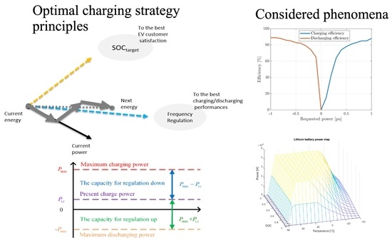
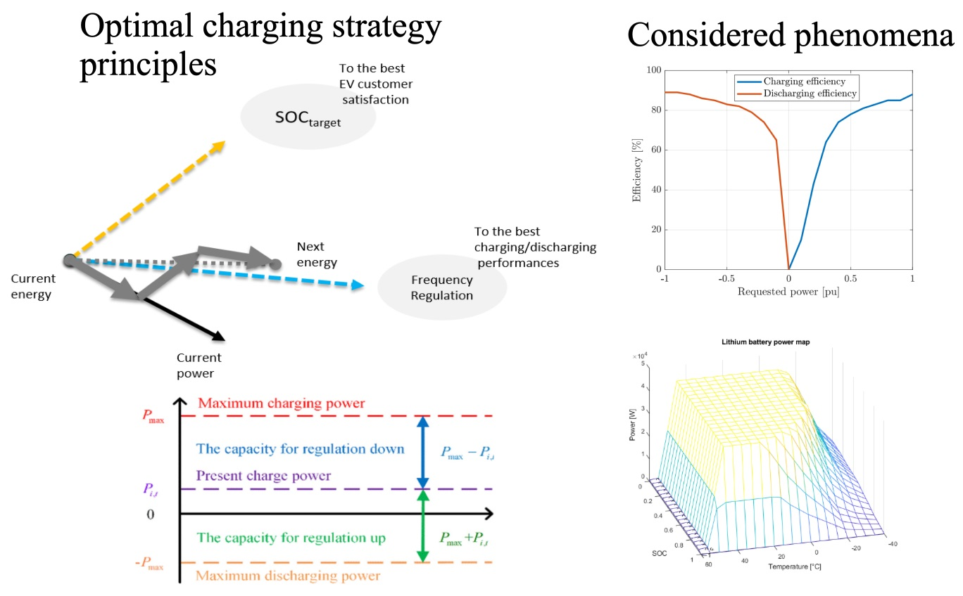
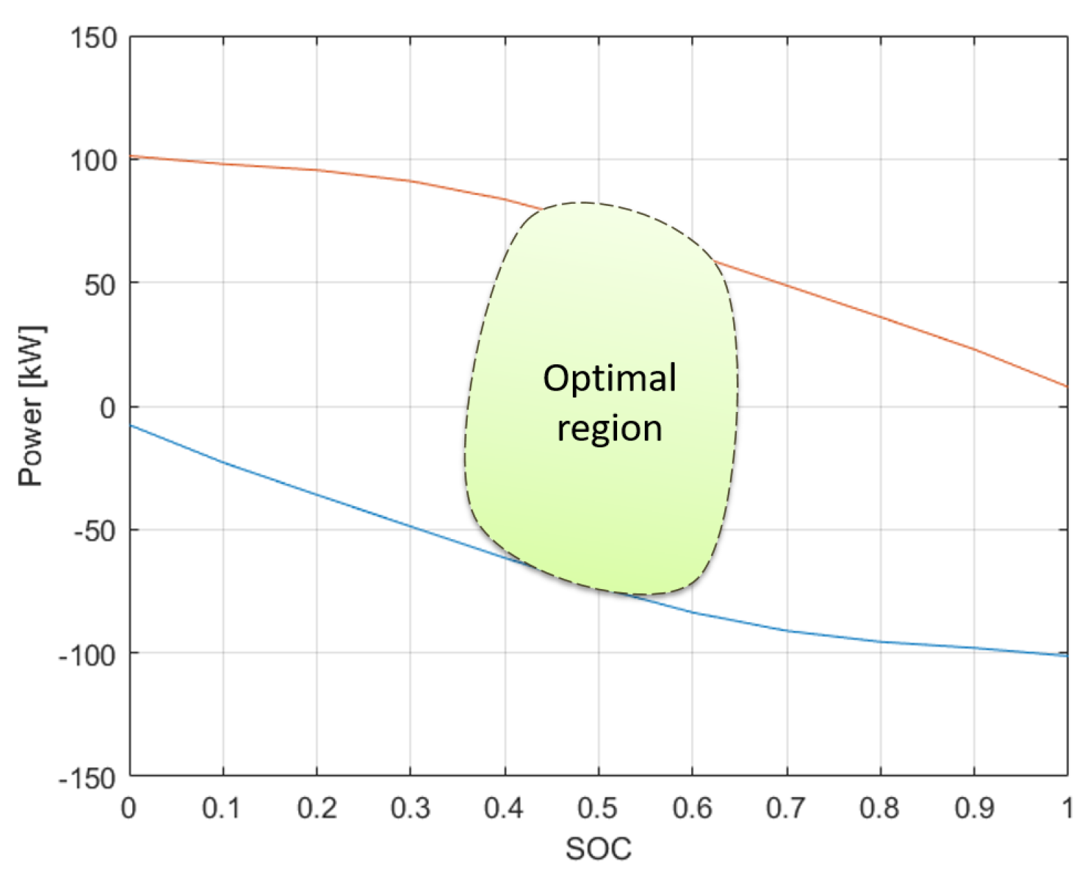
  • Take into account the SoC and temperature dependence of regulation capacity and keeping the total regulation capacity in the optimal zone;
  • Control the bi-directional charging of EVs (V2G), taking into account both the power demand of the grid operator and the satisfaction of the SoC target of the EVs’ users.
The remaining sections of the paper are structured as follows: In Section 2, the optimization problem modeling is detailed. The simulation results of the control strategy are presented in Section 3. Finally, in Section 4, the paper conclusion and future works are discussed.

2. Optimization Problem Modeling

In this paper, we formulate the EV charging problem as a power dispatch problem and consider two distinct cases:
  • Case 1 (namely P1): the standard power dispatch problem with a frequency disturbance. In this context, the main goal is to charge EVs, but the idea is to also keep a regulation capability of up and down, i.e., to keep EVs in an optimal region to be able to better face the second case;
  • Case 2 (namely P2): the frequency regulation problem with a power request from or to the power grid. The main goal, then, becomes to answer this power demand emerging from the power grid, while trying to consider EVs charging expectations.
In P1, the problem is expressed as a general quadratic optimization problem, where the objective function aggregates two criteria:
F 1 = w 1 C 1 2 + w 2 C 2 2
The criterion C 1 computes the sum of gaps between an energy target and the energy in EV batteries at each time step. This target is determined by considering the optimal region to obtain the best regulation capability (up and down) as depicted on Figure 1.
C 1 = ( E i 1 + j = 1 N E V P i j Δ t ) E i r e f
where E i is calculated by the given Equation (3):
E i = j = 1 N E V S o C i j · E b a t t j · S o H j
E i r e f is tracked to maintain the regulation capacity at the maximal value and is computed (considering Figure 1 optimal region) as follows:
E i r e f = j = 1 N E V S o C i r e f · E b a t t j · S o H j
As shown by the example of Figure 1, the best tradeoff between charging and discharging capability is at a SoC of 0.5 with a maximal charging power of 80 kW and a discharging power of −80 kW. The optimal region is defined between a SoC of 0.4 and a SoC of 0.6, where both charging and discharging powers stay high. In these conditions, EVs can be managed in a flexible way to 1. charge their batteries and 2. answer a power demand from or to the grid. In order to give a priority to the charging of EVs, the optimal SoC ( S o C i r e f ) may be set over 0.5. In our benchmark, we set S o C i r e f to 0.6.
At the global EV fleet level, the global strategy has to consider various subtleties to deal with conflicting objectives, such that the SoC of EVs is maximized at the end of the day. The total available energy stays in an optimal region and obtains the best response for a frequency regulation demand, as is illustrated on Figure 2.
A frequency deviation and its duration are unpredictable when considering the planning horizon of a day. Then, the EV fleet must be able, at any moment, to face any disturbances in the power grid, but must be able of taking into account two opposing criteria for each EV:
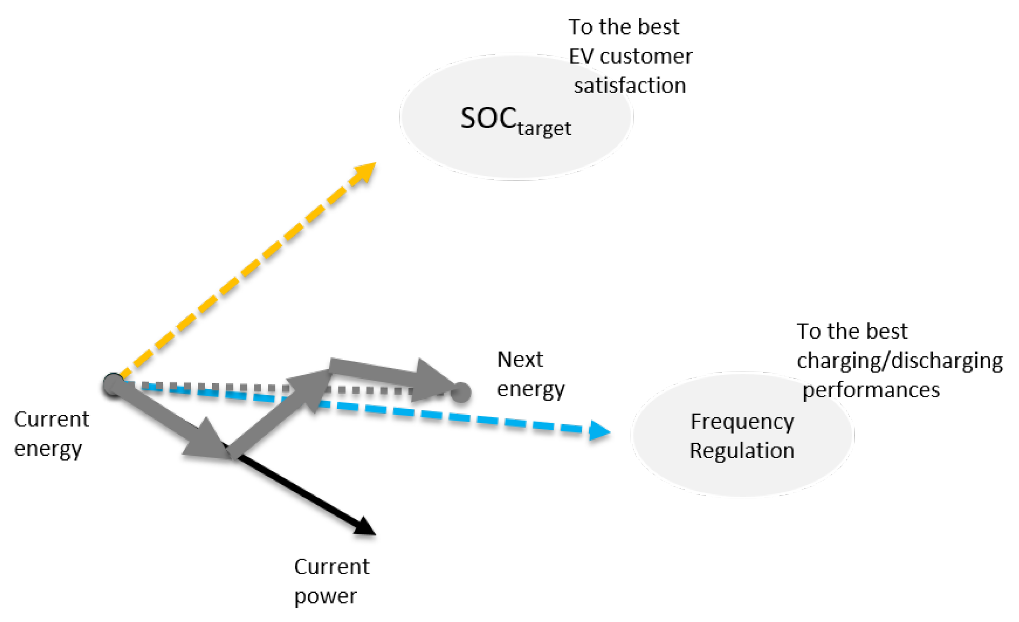
  • To charge its battery in order to obtain a high SoC to meet the EV owner needs (>0.7);
  • To keep the SoC within an optimal range to improve the capability of the fleet to answer a frequency control request (>0.4 and <0.6).
This strategy allows a better power management for the EV fleet charging and a quick response to the power request in case of a frequency deviation.
Then, the purpose of the criterion C 2 is to keep the EV charging, such that the total power approaches P i r e f ; thus, the total available energy stored in the EVs increases gradually to the maximal capacity of the EVs’ battery by the end of the day (cf. Figure 3). The strategy of increasing the EVs’ SoC at the end of the day is fully justified because of high-power demands during the peak period between 6 PM and 10 PM. Thus, there is a necessity to discharge EVs for the relief of the power grid.
C 2 = ( j = 1 N E V P i j ) P i r e f
P i r e f is defined as the average power that must be used to reach E s a t u r a t i o n at the end of the day, with a total station opening time of t o p hours. The detailed expression of P i r e f is given in the following equations:
E s a t u r a t i o n = j = 1 N E V S o C l i m i t · E b a t t j · S o H j
E i r e m a i n = E s a t u r a t i o n E i
P i r e f = E i r e m a i n t o p
P1 aims to prepare the EV fleet to respond to any power request by keeping the average SoC of the EV fleet in the optimal region and by charging the EVs that have a higher priority. However, the main goal of P2 is to minimize the error between the requested power and the used charging power, as well as to maximize the charging efficiency of the fleet.
When there is a power request, P2 is activated and the optimization problem is expressed as a multi-criteria minimization:
F 2 = w 3 C 3 2 + w 4 C 4
The purpose of criterion C 3 is to offer the best answer to the power request by minimizing the tracking error, i.e., P P r e q u e s t :
C 3 = ( j = 1 N E V P i j ) P i r e q u e s t
Criterion C 4 take into account the chargers’ efficiency to minimize the losses related to this component.
C 4 = j = 1 N E V P i j ( 1 η ( P i j ) )
P1 and P2 have a different objective function, but they are subjected to the same set of constraints related to physical limits or operational constraints.
The amount of power used to charge or discharge a battery that is bounded is defined in (12):
P i j C i j P i j D i j
The definition of C i j and D i j is given by the following equations:
C i j = s i j · α i j , u b · P i j , m a x + D i j = s i j · α i j , l b · P i j , m a x
P i j , m a x + = m i n ( P c h p t + j , P C h a r g e r + j , P i , B a t + j ) P i j , m a x = m a x ( P c h p t j , P C h a r g e r j , P i , B a t j )
s i j , α i j , u b , and α i j , u b are defined in the Equations (15)–(17) as follows:
s i j = 1 , pluged-in 0 , pluged-out
α i j , u b = 1 , S o C i j < 0.9 0 , S o C i j 0.9
α i j , l b = 1 , S o C i j 0.2 0 , S o C i j < 0.2
To avoid overloading the transformers, a maximal power limits the sum of power that is dispatched to EVs for each time slot:
j = 1 N E V P i j P t o t a l
The SoC of EVs is dynamically evaluated through the following equations:
In charging mode : P i j 0 S o C i + 1 j = S o C i j + η ( P i j ) P i j · Δ t E b a t t j · S o H j In discharging mode : P i j < 0 S o C i + 1 j = S o C i j + ( P i j / η ( P i j ) ) · Δ t E b a t t j · S o H j
For the sake of simplicity, the joule heat generation is considered as evenly distributed. As a consequence, the temperature in battery cells is also considered well distributed. Then, for the estimation of the temperature, a first-order equation is used:
T i + 1 j = T i j + 1 m j C p j ( P j o u l e , i j + P c o n v e c t i v e , i j )
To compute the joule power, a linear approximation is used:
P j o u l e , i j = k j × P i j i , j
The Newton law is applied for computation of the convective power:
P c o n v e c t i v e , i j = T i j T i o u t R t h _ o u t j i = 1 , , N
The presented results were obtained with the MATLAB optimization toolbox when using f m i n c o n with an Intel Core i7 CPU @ 2.70GHz.

3. Simulations and Results

The parameters used for the simulations are summarized in Table 1. The default full-rate power for the charging stations was 22 kW.

3.1. Impacts of the Charger Efficiency

The charger efficiency can have a significant impact on the amount of energy put in batteries. Approximating the efficiency with a constant value may lead to a low accuracy in the results, as shown in Figure 4, with variations ranging from 0.72 to 0.96 percent. The fixed arrival and departure times (see Table 2), with a constant number of EVs, were used to focus on the tracking errors related to the proposed strategy.
Figure 5 shows the results obtained on a scenario with a frequency regulation between 8:00 to 18:00. In this case, P2 was used, and multiple charging and discharging decisions were applied, thus increasing the energy transfers between the power grid and the EVs. By using efficiency as a function of power (see Figure 4), the tracking error is much smaller compared to a fixed efficiency (around the kilowatt threshold). In the first case with a constant efficiency, the tracking error is at the order of magnitude of kW when compared to the varying efficiency scenario where it falls down to the order of magnitude of W.

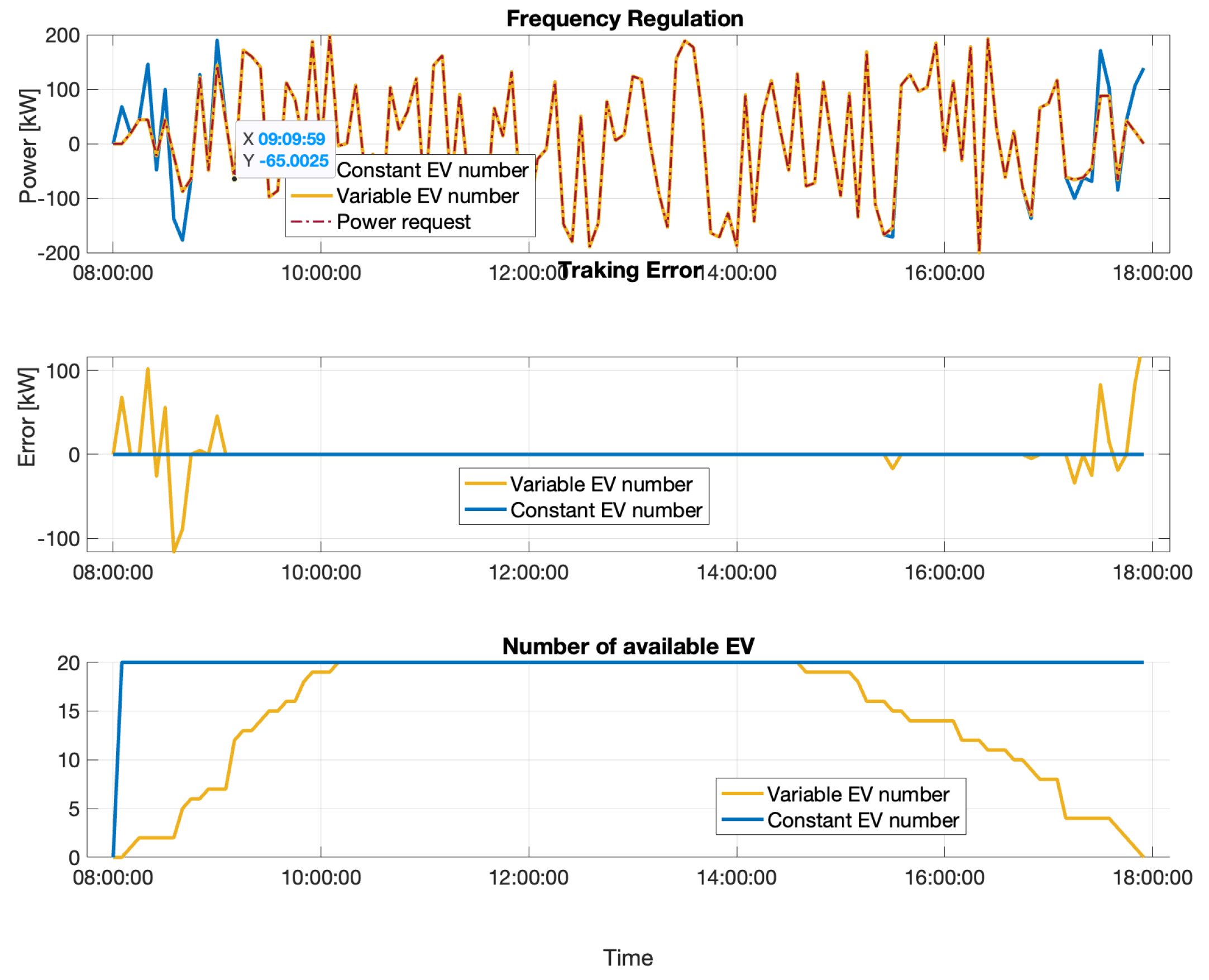
3.2. Impacts of the Number of EVs

Figure 6 shows a comparison of two scenarios for the same power request (the parameters are summarized in Table 3. In the first case (blue line), the number of EVs is constant, whereas in the more realistic second case (yellow line), it varies with all arrivals between 8:00 to 10:00 and with the departures between 15:00 and 18:00. In the first case, tracking errors are low, whereas in the second case, it becomes more significant as the number of EVs is low. This is due to the low-regulation capacity when fewer EVs are available at the charging station. As shown in Figure 6, the tracking error is close to zero when the number of EVs is greater than ten. Then, the EVs offer a high-regulation reserve. In such a scenario, the charging station cannot ensure a regulation request with a low number of EVs and another energy storage solution should be considered to compensate for the lack of EVs in certain periods of the day.

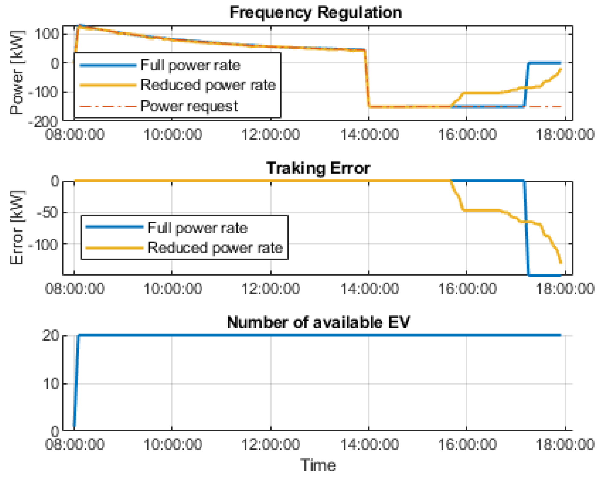
3.3. Impact of Long Frequency Drops and the Maximum Charging Rate

A power plant shutdown or failure may lead to high-frequency drops for a long period of time. This critical situation may lead to a blackout on the power network. The simulation detailed in this subsection shows how EVs can play a crucial role in supporting the power grid. Two scenarios were investigated with a fixed number of available EVs. The first one considered a full power rate of 22 kW, whereas in the second scenario, each EV selected a random maximal power rate from 3.2 ,   7.4 ,   11 , and 22. In the charging station, the charging points had the following ratios: 30 % ,   30 % ,   20 % , and 20 % , respectively.
As shown on Figure 7, the EVs were charged until 14:00—where a high-frequency drop occurred. In both scenarios, the power request could not be met until the end, but in both cases support was offered for most of the duration.
The SoC evolution of the EVs is illustrated in Figure 8 for the first scenario and in Figure 9 for the second one. We can see that the constraints for the minimal SoC threshold are active at the end of the two scenarios and that the tracking errors increase from this moment since no more energy can be taken from EVs.
In the first scenario and before some EVs reached the minimal SoC threshold, the discharge rate was homogeneously divided between all of the EVs. After that event, the slopes of the remaining EVs changed, i.e., the slops went up to the maximal discharge power rate but only for a short period after which all EVs reached the minimal SoC of 0.2. In the second scenario, the maximal discharging power constraint acted to limit the discharging rate. Some EVs were no longer able to supply the grid around 15:45 and the tracking error became sensitive sooner than in the first scenario. However, the supply of the grid was provided until the end, even if it was only for a small amount and even if the decrease in the grid support was smoother.

3.4. Discussions about EV Usage in the Frequency Regulation Market

Previous results show the good behavior of fleets of EVs in terms of participating in frequency regulation. This is even the case with a relatively low number of EVs as the relevant charging strategy maintains their SoC in an optimal region. The ancillary services market is mainly divided into a primary reserve and a secondary reserve, which require different condition to satisfy. These conditions are, in general, specific to each country, but the most common conditions are presented in Table 4.
From the previous results and Table 4, participation with the primary reserve can be ensured by EVs. However, a station should better contain a limited number of charging points, but with a high-charging rate in order to be able to attain the minimum limit of 1MW. The uncertainties about the availability of EVs (arrival and departure times) and their number are not the main issue since the major constraint is the minimum contracted reserve. The duration of the primary reserve activation is 15 min. Since EVs charge for a longer period, the charging station can easily interrupt the charging to satisfy the primary reserve requirements and can resume the charging afterward. This short interruption may not significantly reduce the satisfaction of EV owners in terms of obtaining the expected SoC when leaving at the departure time. In the case of a V2G support, the action may contribute to owners while compensating the extra cycling of the battery.
The case of secondary reserve participation requires a greater capacity than for the primary reserve, mainly because of the longer activation time. Thus, it is better to consider charging stations with a high number of charging points, as well as high-attendance rates with long periods of EVs availability. Depending on the spatial organization of the power network, small charging stations that are close enough can be grouped on the same aggregator to build a virtual station that meet the requirements for secondary reserve participation. In this context, the mix of slow- and fast-charging points is not an issue as demonstrated by our results.

4. Conclusions

This work addresses the possibility of using EVs for the ancillary services related to frequency regulation. This paper describes a strategy to manage EVs to be able to participate in a frequency regulation, as well as in meeting EV owners’ expectations. This strategy is implemented as two optimization problems. The first one addresses the normal situation without any frequency deviation and tries to enforce a maximum-power availability. A SoC target (0.6%) for regulation was defined for the EVs, such that the EVs in this region can better answer any kind of frequency regulation. This criterion is combined with the SoC target defined by EVs owners to satisfy both criteria at the same time. The second optimization problem is used when a frequency regulation request occurs. In this scenario, the objective is also composed of two criteria to be minimized at the same time: the tracking error with the power request and the losses relating to charger efficiencies.
Several simulations were presented to highlight the impact of the charger efficiency, the number of available EVs, and the duration of the frequency regulation request. Most existing works focus on a high number of EVs, but—as we show in this paper—even with as low as 20 EVs, good behavior can be observed in most cases. Thus, this paper discusses the position of EV charging stations for primary and secondary reserve participation.

Author Contributions

Conceptualization, Y.D., M.G. and R.C.; methodology, Y.D. and R.C.; software, Y.D.; validation, Y.D., M.G. and M.A.R.; writing—original draft preparation, Y.D.; writing—review and editing, R.C. and M.G.; visualization, Y.D.; supervision, M.G. and M.A.R.; All authors have read and agreed to the published version of the manuscript.

Funding

This research was funded by the chair between Renault Group and Ecole Centrale de Nantes regarding the performances of electric vehicle propulsion.

Conflicts of Interest

The authors declare no conflict of interest. Mario Alvarado Ruiz is employee of Renault Group Technocentre Guyancourt. The paper reflects the views of the scientists, and not the company.

Abbreviations

The following abbreviations are used in this manuscript:
w 1 , w 2 , w 3 , w 4 Weighting factors
E i Total available energy stored in the EVs
N E V Number of EVs
P i j Charging power of the j-th EV at time i
Δ t Sampling time
E i r e f Energy reference at time i
S o C i j State of charge of the j-th EV in time step i
E b a t t j Battery capacity of the j-th EV
S o H j State of health of the j-th EV’ battery
S o C i r e f SoC reference at time i
P i r e f Power reference at time i
E s a t u r a t i o n Energy threshold of the charging station
S o C l i m i t Maximum SoC limit
E i r e m a i n Remaining energy before reaching
E s a t u r a t i o n time i
t o p Station opening hours
P i r e q u e s t Power request at time i
η Charger efficiency
C i j , D i j Power upper/lower bound of the j-th EV during time step i
s i j ]State of the j-th EV at time i
α i j , u b , α i j , l b Binary variables depending on the SoC of the j-th EV at time i
P i j , m a x + , P i j , m a x Maximal authorized charging/discharging rate for j-th EV at time step i
P c h p t + j , P c h p t j Maximum charging/discharging power of the charging point of the j-th EV
P c h a r g e r + j , P c h a r g e r j Maximum power of the j-th charger in charging or discharging mode
P B a t + , i j , P B a t , i j Maximum accepted/delivered battery’s power of the j-th EV at time i
depending on the SoC and the battery’s temperature
P t o t a l Maximum transformer power of the charging station
m j Mass of the j-th EV battery
C p j Specific heat coefficient of the j-th EV battery
T i j Temperature of the j-th EV battery at time i
P j o u l e , i j Power dissipated by the joule effect of the j-th EV battery at time i
P c o n v e c t i v e , i j Power heat transfer between the battery and the outside of the j-th EV battery
at time i
k j Thermal factor depending on the thermal inertia of the j-th EV battery
T i o u t Outside temperature at time i
R t h _ o u t j Heat convection coefficient between the j-th EV battery and outside

References

  1. Amamra, S.A.; Marco, J. Vehicle-to-Grid Aggregator to Support Power Grid and Reduce Electric Vehicle Charging Cost. IEEE Access 2019, 7, 178528–178538. [Google Scholar] [CrossRef]
  2. Tchagang, A.; Yoo, Y. V2B/V2G on Energy Cost and Battery Degradation under Different Driving Scenarios, Peak Shaving, and Frequency Regulations. World Electr. Veh. J. 2020, 11, 14. [Google Scholar] [CrossRef] [Green Version]
  3. Calearo, L.; Marinelli, M. Profitability of frequency regulation by electric vehicles in Denmark and Japan considering battery degradation costs. World Electr. Veh. J. 2020, 11, 48. [Google Scholar] [CrossRef]
  4. Liu, H.; Hu, Z.; Song, Y.; Lin, J. Decentralized vehicle-to-grid control for primary frequency regulation considering charging demands. IEEE Trans. Power Syst. 2013, 28, 3480–3489. [Google Scholar] [CrossRef]
  5. Xu, X.; Zhang, C.; Gu, L. Decentralized primary frequency regulation control strategy for vehicle-to-grid. In Proceedings of the 2016 3rd International Conference on Systems and Informatics (ICSAI), Shanghai, China, 19–21 November 2016; pp. 217–222. [Google Scholar]
  6. Liu, H.; Qi, J.; Wang, J.; Li, P.; Li, C.; Wei, H. EV dispatch control for supplementary frequency regulation considering the expectation of EV owners. IEEE Trans. Smart Grid 2018, 9, 3763–3772. [Google Scholar] [CrossRef] [Green Version]
  7. Izadkhast, S.; Garcia-Gonzalez, P.; Frías, P. An aggregate model of plug-in electric vehicles for primary frequency control. IEEE Trans. Power Syst. 2015, 30, 1475–1482. [Google Scholar] [CrossRef]
  8. Liu, H.; Huang, K.; Yang, Y.; Wei, H.; Ma, S. Real-time vehicle-to-grid control for frequency regulation with high frequency regulating signal. Prot. Control. Mod. Power Syst. 2018, 3, 13. [Google Scholar] [CrossRef]
  9. Iqbal, S.; Habib, S.; Khan, N.H.; Ali, M.; Aurangzeb, M.; Ahmed, E.M. Electric Vehicles Aggregation for Frequency Control of Microgrid under Various Operation Conditions Using an Optimal Coordinated Strategy. Sustainability 2022, 14, 3108. [Google Scholar] [CrossRef]
  10. Sahu, P.C.; Prusty, R.C.; Panda, S. Frequency regulation of an electric vehicle-operated micro-grid under WOA-tuned fuzzy cascade controller. Int. J. Ambient. Energy 2022, 43, 2900–2911. [Google Scholar] [CrossRef]
  11. Hajiakbari Fini, M.; Golshan, M.E.H.; Martí, J.R. Coordinated Participation of Electric Vehicles and Generating Units in Primary Frequency Control in the Presence of Renewables. IEEE Trans. Transp. Electrif. 2023, 9, 130–141. [Google Scholar] [CrossRef]
  12. Yao, E.; Wong, V.W.S.; Schober, R. Robust Frequency Regulation Capacity Scheduling Algorithm for Electric Vehicles. IEEE Trans. Smart Grid 2017, 8, 984–997. [Google Scholar] [CrossRef]
  13. Wenzel, G.; Negrete-Pincetic, M.; Olivares, D.E.; MacDonald, J.; Callaway, D.S. Real-time charging strategies for an electric vehicle aggregator to provide ancillary services. IEEE Trans. Smart Grid 2018, 9, 5141–5151. [Google Scholar] [CrossRef] [Green Version]
  14. Liu, H.; Huang, K.; Wang, N.; Qi, J.; Wu, Q.; Ma, S.; Li, C. Optimal dispatch for participation of electric vehicles in frequency regulation based on area control error and area regulation requirement. Appl. Energy 2019, 240, 46–55. [Google Scholar] [CrossRef]
  15. Kaur, K.; Kumar, N.; Singh, M. Coordinated power control of electric vehicles for grid frequency support: MILP-based hierarchical control design. IEEE Trans. Smart Grid 2019, 10, 3364–3373. [Google Scholar] [CrossRef]
  16. Kaur, K.; Singh, M.; Kumar, N. Multiobjective optimization for frequency support using electric vehicles: An aggregator-based hierarchical control mechanism. IEEE Syst. J. 2019, 13, 771–782. [Google Scholar] [CrossRef]
  17. Jeong, H.; Jeong, M.; Lee, S. Vehicle-To-Grid Based Frequency Regulation Method In An Isolated Microgrid Considering Charging Requests Of Electric Vehicles. In Proceedings of the 2019 International Conference and Exhibition on Electricity Distribution (CIRED), Madrid, Spain, 3–6 June 2019; pp. 1–5. [Google Scholar]
  18. Wang, M.; Mu, Y.; Li, F.; Jia, H.; Li, X.; Shi, Q.; Jiang, T. State Space Model of Aggregated Electric Vehicles for Frequency Regulation. IEEE Trans. Smart Grid 2019, 11, 981–994. [Google Scholar] [CrossRef]
  19. Khooban, M.H.; Gheisarnejad, M. A Novel Deep Reinforcement Learning Controller Based Type-II Fuzzy System: Frequency Regulation in Microgrids. IEEE Trans. Emerg. Top. Comput. Intell. 2020, 5, 689–699. [Google Scholar] [CrossRef]
  20. Dahmane, Y.; Ghanes, M.; Chenouard, R.; Alvarado-Ruiz, M. Coordinated Charging of Large Electric Vehicle Fleet in a Charging Station With Limited Transformer Power. In Proceedings of the 2020 4th IEEE Conference on Control Technology and Applications (IEEE CCTA), Montreal, QC, Canada, 24–26 August 2020; pp. 1–6. [Google Scholar]
  21. Dahmane, Y.; Ghanes, M.; Chenouard, R.; Alvarado-Ruiz, M. Decentralized Control of Electric Vehicle Smart Charging for Cost Minimization Considering Temperature and Battery Health. In Proceedings of the 2019 IEEE International Conference on Communications, Control, and Computing Technologies for Smart Grids (SmartGridComm), Beijing, China, 21–23 October 2019; pp. 1–6. [Google Scholar] [CrossRef]
  22. Ziras, C.; Zecchino, A.; Marinelli, M. Response accuracy and tracking errors with decentralized control of commercial v2g chargers. In Proceedings of the 2018 Power Systems Computation Conference (PSCC), Dublin, Ireland, 11–15 June 2018; pp. 1–7. [Google Scholar]
  23. Ye, X.; Ji, T.; Li, M.; Wu, Q. Optimal control strategy for plug-in electric vehicles based on reinforcement learning in distribution networks. In Proceedings of the 2018 International Conference on Power System Technology (POWERCON), Guangzhou, China, 6–8 November 2018; pp. 1706–1711. [Google Scholar]
  24. Zeller, M.; Blake, S.; Cedillos, D.; Gertz, A.; Boyd, E. Flexibility within the Electrical Systems through Demand Side Response: Introduction to Balancing Products and Markets in Germany, France, and the UK; Technical Report 3027514; European Commission: Brussels, Belgium, 2017.
Figure 1. Optimal capability region for charging or discharging lithium−ion batteries, depending on their SoC.
Wevj 14 00152 g001
Figure 2. An illustration of two conflicting objectives.
Wevj 14 00152 g002
Figure 3. Example of a reference energy and actual energy in the scope of a day.
Wevj 14 00152 g003
Figure 4. EV charger efficiency.
Wevj 14 00152 g004
Figure 5. Frequency regulation (FR) signal, and the impact of charger efficiency response errors.
Wevj 14 00152 g005
Figure 6. FR signal, response error, and EV availability.
Wevj 14 00152 g006
Figure 7. FR signal, response error, and EV availability.
Wevj 14 00152 g007
Figure 8. The SoC evolution of every EV in the charging station for a full power rate of 22 kW.
Wevj 14 00152 g008
Figure 9. The SoC evolution of each EV in the charging station at a reduced power rate.
Wevj 14 00152 g009
Table 1. EV parameters used for simulations.
ParametersValue
Sampling time5 min
Maximum number of EVs20
Battery capacity60 kWh
Starting SoC [ 0.1 , 0.6 ]
Desired SoC [ 0.3 , 0.9 ]
Maximum/minimum SoC0.9/0.2
Table 2. Simulation parameters of EVs in Section 3.1.
ParametersTime (h)
Arrival times8 h
Departure times18 h
Table 3. Simulation parameters of the EVs in Section 3.2.
ParametersTime (h)
Arrival times N ( 9 , 0.5 )
Departure times N ( 17 , 0.5 )
Table 4. General condition of the primary and secondary reserves [24].
Primary ReserveSecondary Reserve
Dynamic of activation 50 % within 15 s and 100 % of the reserve enabled within 30 s 100 % of the reserve activated within 5 min
Duration of activationMaximum of 15 minunlimited during the duration of the contract
Minimum power1 MW5 MW
Power directionNegative AND PositiveNegative OR Positive
Disclaimer/Publisher’s Note: The statements, opinions and data contained in all publications are solely those of the individual author(s) and contributor(s) and not of MDPI and/or the editor(s). MDPI and/or the editor(s) disclaim responsibility for any injury to people or property resulting from any ideas, methods, instructions or products referred to in the content.

