
A Critical Comparison of the Cuk and the Sheppard–Taylor Converter

 ,
,  , ,
, ,  and
and
Abstract
:1. Introduction
2. Modeling of the Converters
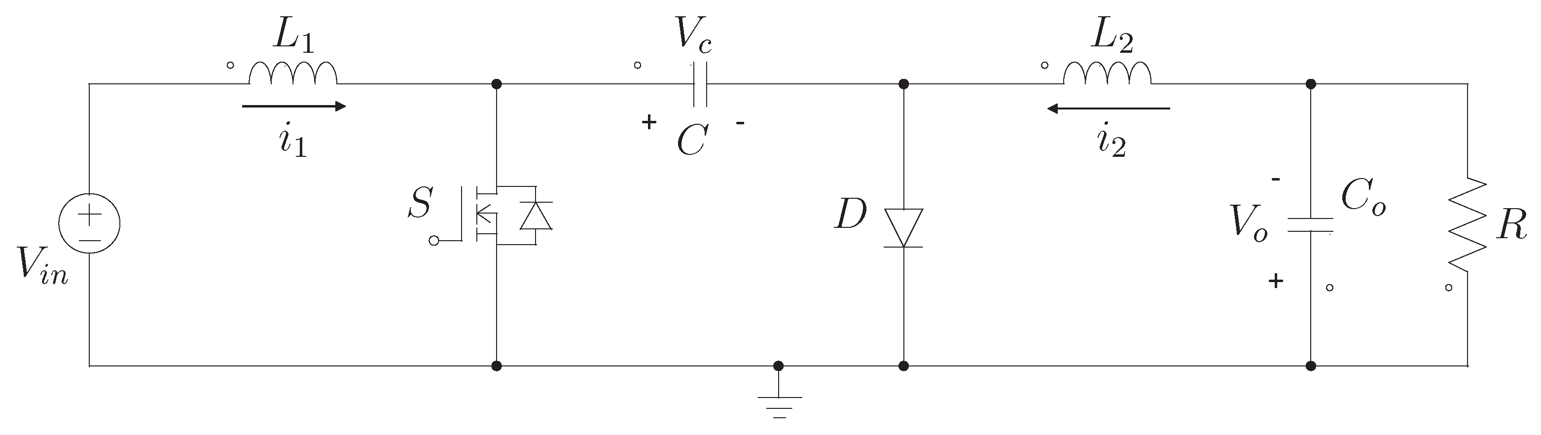
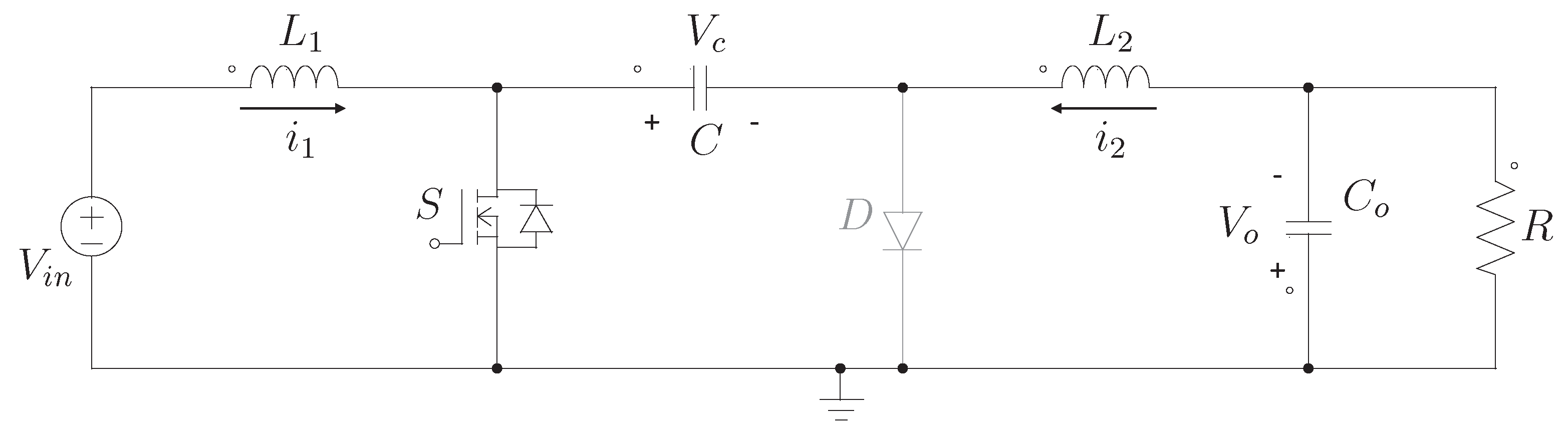
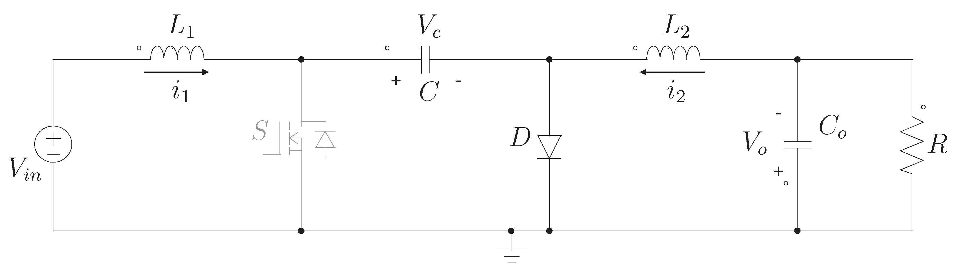
2.1. Cuk Converter
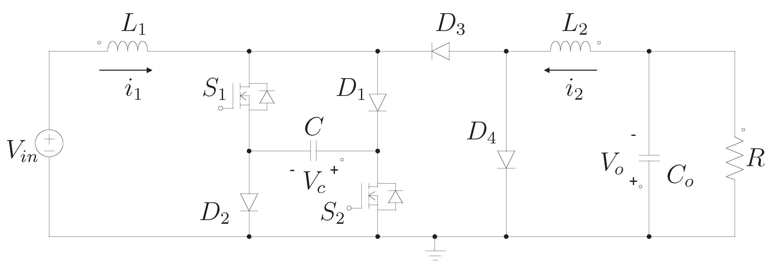
2.2. Sheppard–Taylor Converter
3. Simulation Results
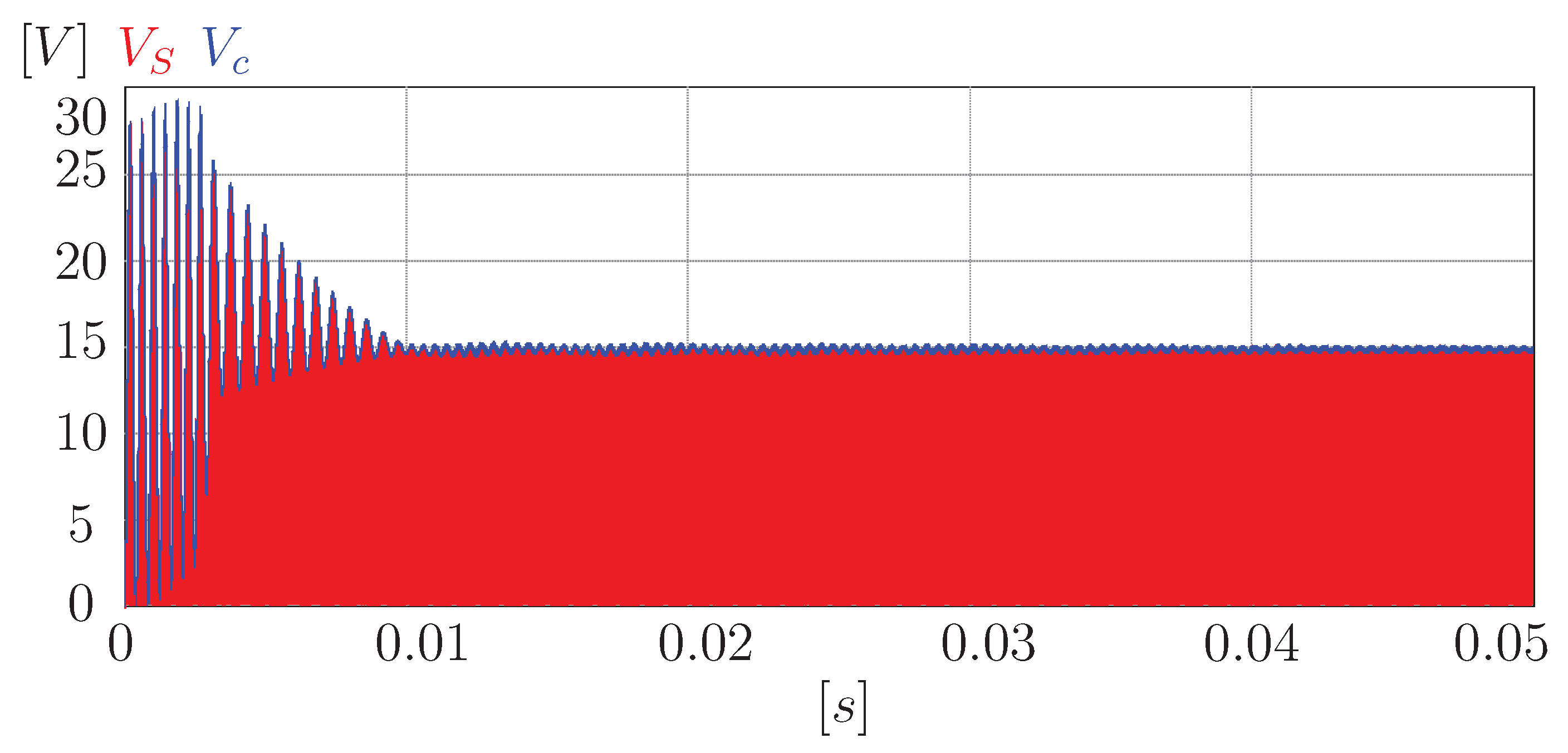
3.1. Cuk Converter
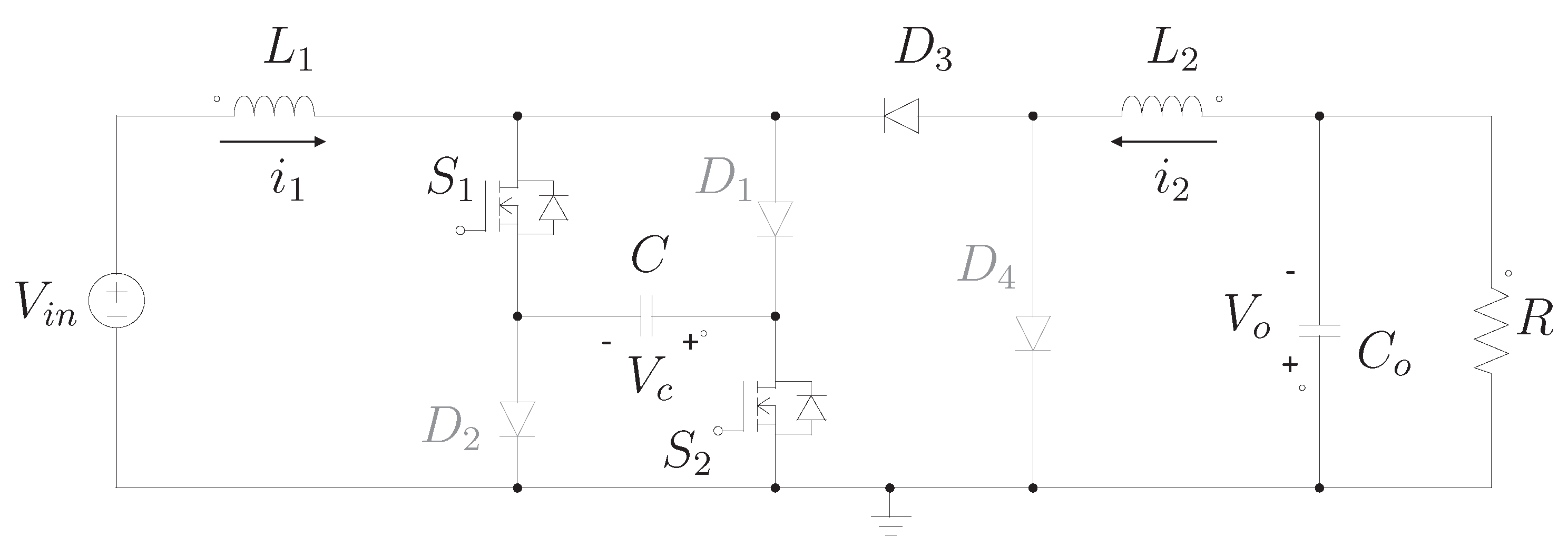
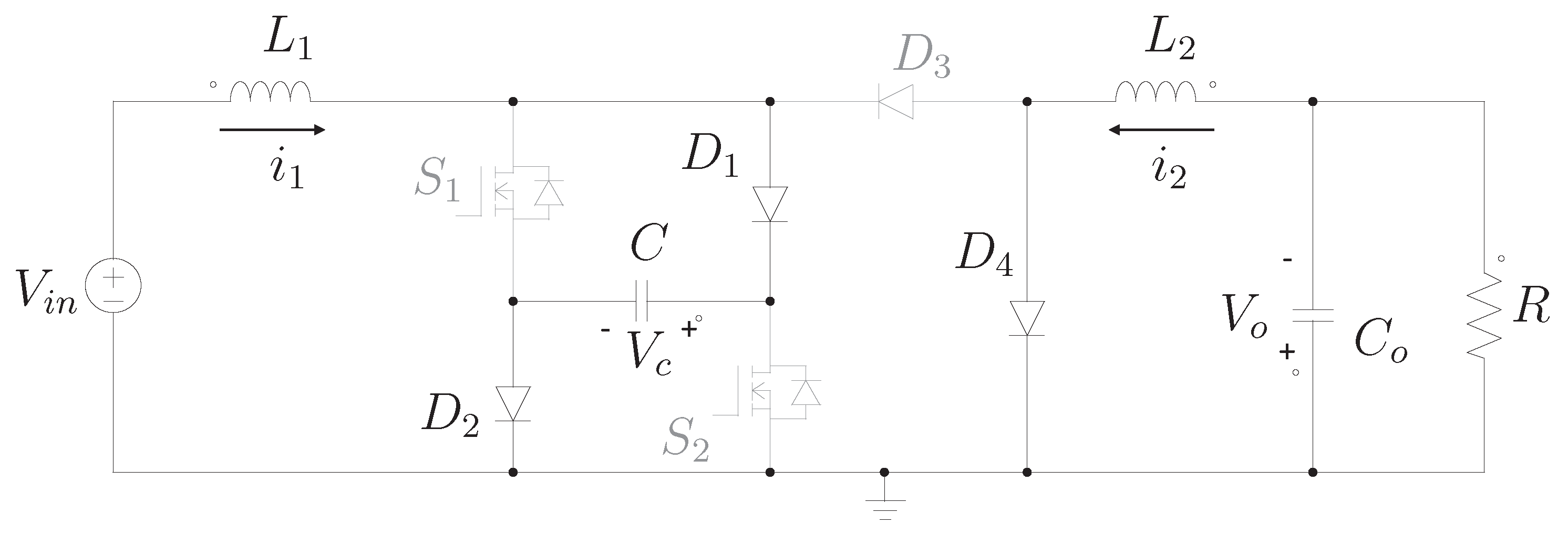
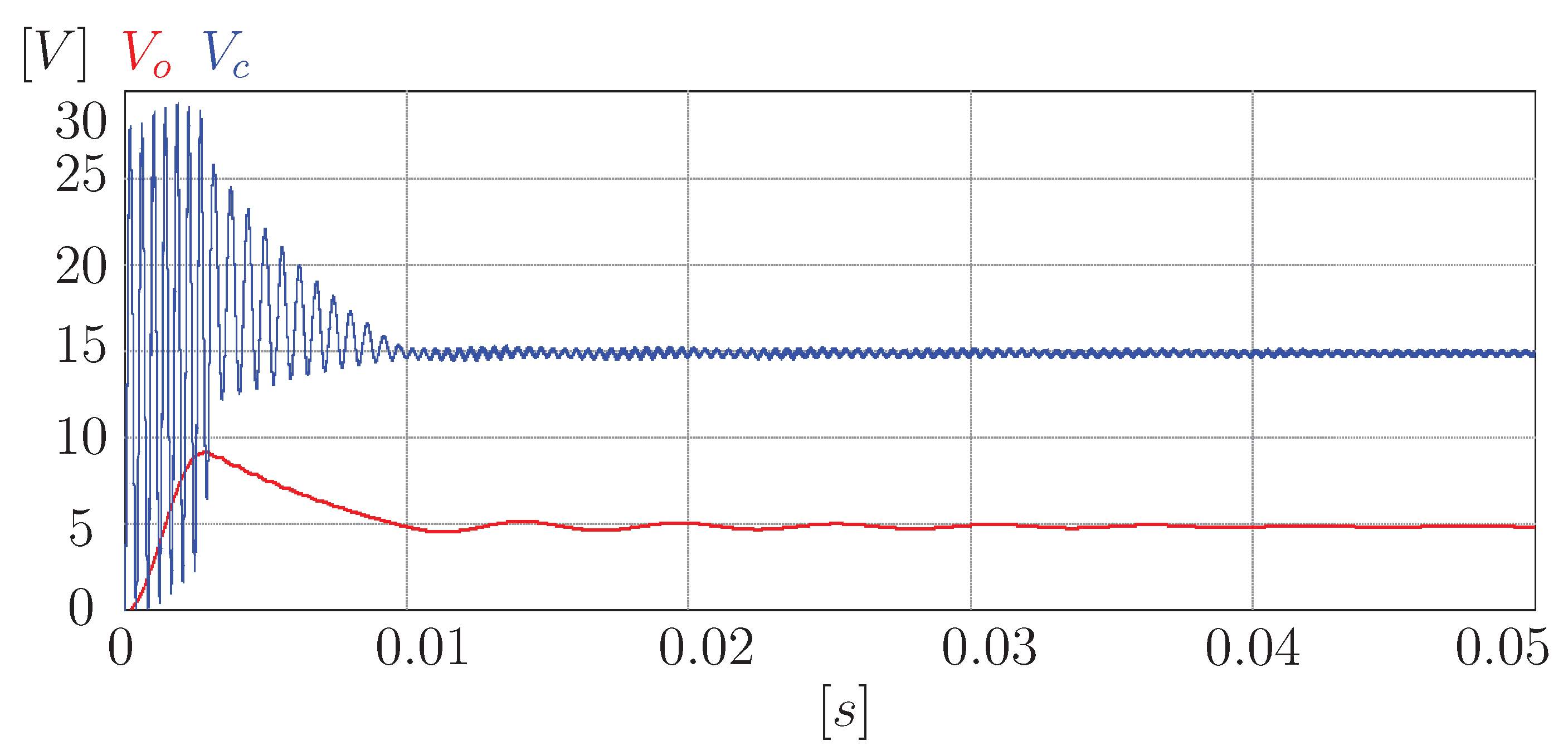
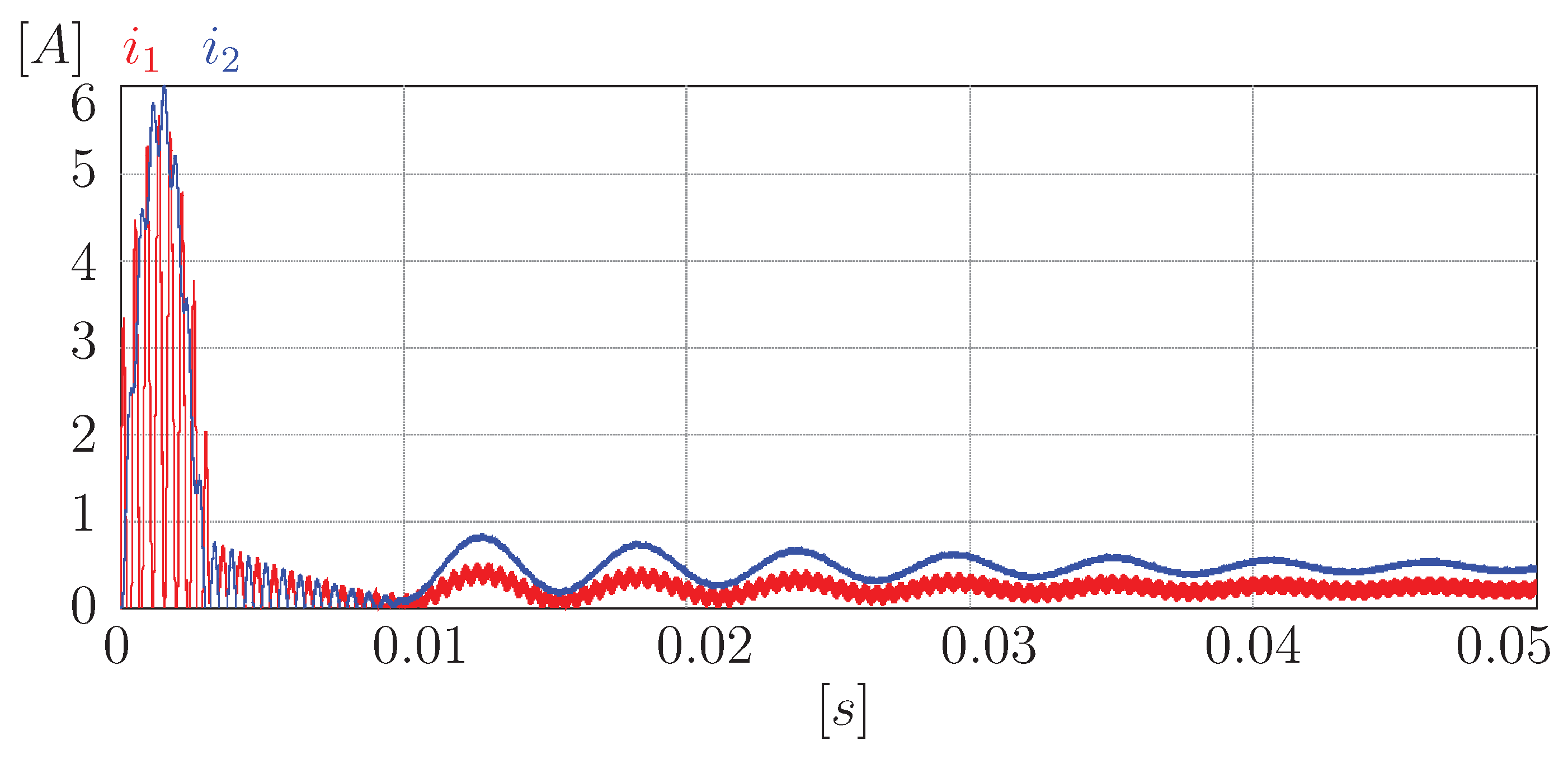
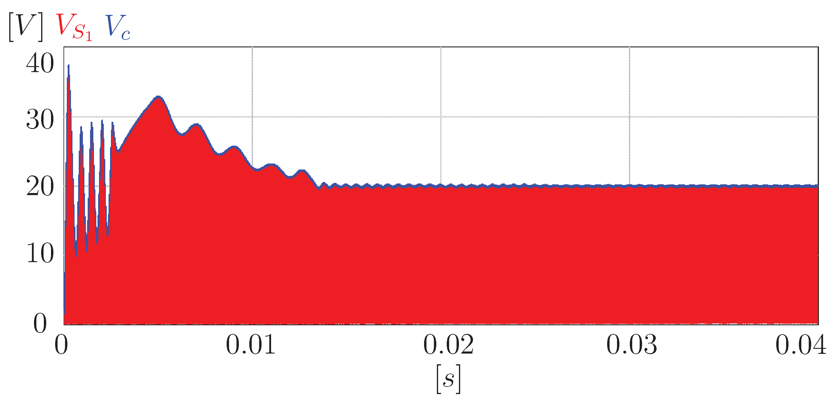
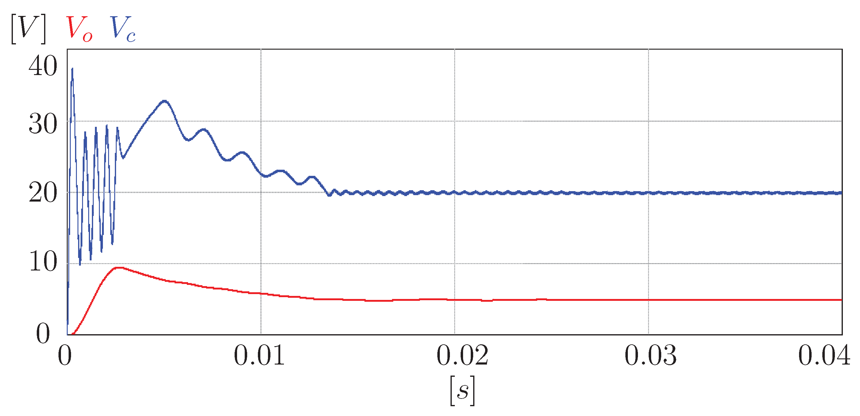
3.2. Sheppard–Taylor Converter
4. Discussion
5. Conclusions
Author Contributions
Funding
Data Availability Statement
Conflicts of Interest
References
- Estévez-Bén, A.A.; Alvarez-Diazcomas, A.; Rodríguez-Reséndiz, J. Transformerless multilevel voltage-source inverter topology comparative study for PV systems. Energies 2020, 13, 3261. [Google Scholar] [CrossRef]
- Tzermias, G.; Akehurst, S.; Burke, R.; Brace, C.; George, S.; Bernards, J.; Smith, C. Methodology for the Optimisation of Battery Hybrid Energy Storage Systems for Mass and Volume Using a Power-To-Energy Ratio Analysis. Batteries 2021, 7, 37. [Google Scholar] [CrossRef]
- Kusch-Brandt, S. Urban Renewable Energy on the Upswing: A Spotlight on Renewable Energy in Cities in REN21’s “Renewables 2019 Global Status Report”. Resources 2019, 8, 139. [Google Scholar] [CrossRef] [Green Version]
- Wang, Y.; Li, W.; Liu, Z.; Li, L. An Energy Management Strategy for Hybrid Energy Storage System Based on Reinforcement Learning. World Electr. Veh. J. 2023, 14, 57. [Google Scholar] [CrossRef]
- Alvarez-Diazcomas, A.; López, H.; Carrillo-Serrano, R.V.; Rodríguez-Reséndiz, J.; Vázquez, N.; Herrera-Ruiz, G. A novel integrated topology to interface electric vehicles and renewable energies with the grid. Energies 2019, 12, 4091. [Google Scholar] [CrossRef] [Green Version]
- Bhajana, V.V.S.K.; Drabek, P.; Jara, M.; Peroutka, Z. Comparison of main design concepts of auxiliary drives for DC catenary fed light traction vehicles: SiC JFET vs. Si IGBT technology. EPE J. 2020, 31, 17–31. [Google Scholar] [CrossRef]
- Lee, H.; Smet, V.; Tummala, R. A review of SiC power module packaging technologies: Challenges, advances, and emerging issues. IEEE J. Emerg. Sel. Top. Power Electron. 2019, 8, 239–255. [Google Scholar] [CrossRef]
- Rashid, M.H. Power Electronics Handbook; Butterworth-Heinemann: Oxford, UK, 2017. [Google Scholar]
- Hidalgo, H.; Vázquez, N.; Orosco, R.; Huerta-Ávila, H.; Pinto, S.; Estrada, L. Floating Interleaved Boost Converter with Zero-Ripple Input Current Using Variable Inductor. Technologies 2023, 11, 21. [Google Scholar] [CrossRef]
- Koundi, M.; El Idrissi, Z.; El Fadil, H.; Belhaj, F.Z.; Lassioui, A.; Gaouzi, K.; Rachid, A.; Giri, F. State-Feedback Control of Interleaved Buck–Boost DC–DC Power Converter with Continuous Input Current for Fuel Cell Energy Sources: Theoretical Design and Experimental Validation. World Electr. Veh. J. 2022, 13, 124. [Google Scholar] [CrossRef]
- Cuk, S.; Middlebrook, R. A new optimum topology switching dc-to-dc converter. In Proceedings of the 1977 IEEE Power Electronics Specialists Conference, Palo Alto, CA, USA, 14–16 June 1977; IEEE: Piscataway, NJ, USA, 1977; pp. 160–179. [Google Scholar]
- Zhang, Z.; Cuk, S. A high efficiency 500 W step-up Cuk converter. In Proceedings of the Proceedings IPEMC 2000—Third International Power Electronics and Motion Control Conference (IEEE Cat. No. 00EX435), Beijing, China, 15–18 August 2000; IEEE: Piscataway, NJ, USA, 2000; Volume 2, pp. 909–914. [Google Scholar]
- Durán, E.; Galán, J.; Andújar, J.; Sidrach-de Cardona, M. A new method to obtain IV characteristics curves of photovoltaic modules based on SEPIC and cuk converters. EPE J. 2008, 18, 5–15. [Google Scholar] [CrossRef]
- Cocor, A.; Florescu, A.; Popescu, A.M.; Stoichescu, D.A.; Oprea, S. Power supply blocks with Cúk and self-lift Cúk converters for telecommunication sites. In Proceedings of the 2014 International Symposium on Fundamentals of Electrical Engineering (ISFEE), Bucharest, Romania, 28–29 November 2014; IEEE: Piscataway, NJ, USA, 2014; pp. 1–6. [Google Scholar]
- Maroti, P.K.; Padmanaban, S.; Wheeler, P.; Blaabjerg, F.; Rivera, M. Modified high voltage conversion inverting cuk DC-DC converter for renewable energy application. In Proceedings of the 2017 IEEE Southern Power Electronics Conference (SPEC), Puerto Varas, Chile, 4–7 December 2017; IEEE: Piscataway, NJ, USA, 2017; pp. 1–5. [Google Scholar]
- Kumar, K.; Babu, N.R.; Prabhu, K. Analysis of integrated Boost-Cuk high voltage gain DC-DC converter with RBFN MPPT for solar PV application. In Proceedings of the 2017 Innovations in Power and Advanced Computing Technologies (i-PACT), Vellore, India, 21–22 April 2017; IEEE: Piscataway, NJ, USA, 2017; pp. 1–6. [Google Scholar]
- Pandey, R.; Singh, B. A power-factor-corrected LLC resonant converter for electric vehicle charger using Cuk converter. IEEE Trans. Ind. Appl. 2019, 55, 6278–6286. [Google Scholar] [CrossRef]
- Pathare, P.S.; Panchade, V. Power quality improvement of BLDC motor drive using Cuk PFC converter. In Proceedings of the 2020 IEEE International Conference on Computing, Power and Communication Technologies (GUCON), Greater Noida, India, 2–4 October 2020; IEEE: Piscataway, NJ, USA, 2020; pp. 177–181. [Google Scholar]
- Sheppard, D.; Taylor, B. A new converter topology imparts non-pulsating currents to input and output lines. Proc. PCI/Motor-Con 1983, 60–73. [Google Scholar]
- Bist, V.; Singh, B. A PFC based bridgeless Sheppard-Taylor converter fed brushless DC motor drive. In Proceedings of the 2014 Innovative Applications of Computational Intelligence on Power, Energy and Controls with Their Impact on Humanity (CIPECH), Ghaziabad, India, 28–29 November 2014; IEEE: Piscataway, NJ, USA, 2014; pp. 262–267. [Google Scholar]
- Singh, P.; Vinjamuri, R.; Wang, X.; Reisner, D. Design and implementation of a fuzzy logic-based state-of-charge meter for Li-ion batteries used in portable defibrillators. J. Power Sources 2006, 162, 829–836. [Google Scholar] [CrossRef]
- Kushwaha, R.; Singh, B. An EV battery charger based on PFC Sheppard Taylor Converter. In Proceedings of the 2016 National Power Systems Conference (NPSC), Bhubaneswar, India, 19–21 December 2016; IEEE: Piscataway, NJ, USA, 2016; pp. 1–6. [Google Scholar]
- Abedi, M.; Ernzen, B. A hybrid-switching based bridgeless PFC converter for on-board battery chargers using predictive current control. Int. J. Renew. Energy Res. (IJRER) 2012, 2, 645–651. [Google Scholar]
- Tse, C.K.; Chow, M. Single stage high power factor converter using the Sheppard-Taylor topology. In Proceedings of the PESC Record. 27th Annual IEEE Power Electronics Specialists Conference, Baveno, Italy, 23–27 June 1996; IEEE: Piscataway, NJ, USA, 1996; Volume 2, pp. 1191–1197. [Google Scholar]
- Soedibyo; Amri, B.; Ashari, M. The comparative study of Buck-boost, Cuk, Sepic and Zeta converters for maximum power point tracking photovoltaic using P&O method. In Proceedings of the 2015 2nd International Conference on Information Technology, Computer, and Electrical Engineering (ICITACEE), Semarang, Indonesia, 16–18 October 2015; IEEE: Piscataway, NJ, USA, 2015; pp. 327–332. [Google Scholar]
- Sakasegawa, E.; Chishiki, R.; Sedutsu, R.; Soeda, T.; Haga, H.; Kennel, R.M. Comparison of Interleaved Boost Converter and Two-Phase Boost Converter Characteristics for Three-Level Inverters. World Electr. Veh. J. 2023, 14, 7. [Google Scholar] [CrossRef]
- Raghavendra, K.V.G.; Zeb, K.; Muthusamy, A.; Krishna, T.; Kumar, S.; Kim, D.H.; Kim, M.S.; Cho, H.G.; Kim, H.J. A comprehensive review of DC–DC converter topologies and modulation strategies with recent advances in solar photovoltaic systems. Electronics 2020, 9, 31. [Google Scholar] [CrossRef] [Green Version]
- Kanaan, H.Y.; Al-Haddad, K. A unified approach for the analysis of single-phase power factor correction converters. In Proceedings of the IECON 2011—37th Annual Conference of the IEEE Industrial Electronics Society, Melbourne, VIC, Australia, 7–10 November 2011; IEEE: Piscataway, NJ, USA, 2011; pp. 1167–1172. [Google Scholar]
- Mondal, S.; Nandi, A.; Mallick, I.; Ghosh, C.; Giri, A. Performance evaluation of brushless DC motor drive for three different types of MOSFET based DC-DC converters. In Proceedings of the 2017 Devices for Integrated Circuit (DevIC), Kalyani, India, 23–24 March 2017; IEEE: Piscataway, NJ, USA, 2017; pp. 589–593. [Google Scholar]
- Shen, Y.; Xia, J.; Cai, C. Flicker-Free LED Driver Based on Cuk Converter with Integrated Magnetics. World Electr. Veh. J. 2023, 14, 75. [Google Scholar] [CrossRef]
- Xie, W.; Luo, W.; Qin, Y. Integrated DC/DC Converter Topology Study for Fuel Cell Hybrid Vehicles with Two Energy Sources. World Electr. Veh. J. 2023, 14, 9. [Google Scholar] [CrossRef]
- Wang, X.; Tan, Z.; Cai, L.; Lei, G.; Dai, N. Bi-Directional Cuk Equalizer-Based Li-Ion Battery Pack Equalization Control Strategy Research. World Electr. Veh. J. 2023, 14, 86. [Google Scholar] [CrossRef]
- Singh, B.; Bist, V. An Improved Power Quality Based Sheppard–Taylor Converter Fed BLDC Motor Drive. J. Inst. Eng. (India) Ser. B 2014, 96, 327–337. [Google Scholar] [CrossRef]
- Chitra, L.; Kumar, S.; Sarang, K.P.; Clinton, J. High Gain Sheppard Taylor Fed EV in a Grid Connected PV System. In Proceedings of the 2023 Third International Conference on Artificial Intelligence and Smart Energy (ICAIS), Coimbatore, India, 2–4 February 2023; IEEE: Piscataway, NJ, USA, 2023. [Google Scholar] [CrossRef]
- Ang, S.; Oliva, A.; Griffiths, G.; Harrison, R. Power-Switching Converters; CRC Press: Boca Raton, FL, USA, 2010. [Google Scholar]
- Shen, C.L.; Chen, L.Z.; Chen, H.Y. Dual-input isolated DC-DC converter with ultra-high step-up ability based on sheppard taylor circuit. Electronics 2019, 8, 1125. [Google Scholar] [CrossRef] [Green Version]
- Huertas, J.I.; Mogro, A.E.; Jiménez, J.P. Configuration of Electric Vehicles for Specific Applications from a Holistic Perspective. World Electr. Veh. J. 2022, 13, 29. [Google Scholar] [CrossRef]


| Reference/Year | Contribution to the Field of Study |
|---|---|
| [30] | In this paper, a flicker-free LED driver based on an isolated Cuk converter with integrated magnetic technique is proposed. Two inductors and a power transformer are combined into one magnetic core to eliminate the wave current as much as possible. |
| [31] | In this study is an optimized on-board integrated DC/DC converter with a non-isolated multi-port scheme that integrates a unidirectional port for the fuel cell and a bidirectional port for the battery and load. This can achieve combined energy supply and recovery with a single integrated converter, effectively overcoming the above disadvantages. |
| [32] | The authors perform an improved bidirectional Cuk equalizer (BCEQ) structure based on a variable-domain fuzzy PID (VFPID) control equalization strategy which is recommended in stages. |
| [33] | This paper deals with the design and analysis of a power factor correction-based Sheppard–Taylor converter-fed brushless DC motor (BLDCM) drive. |
| [34] | This paper proposes a high-gain Sheppard–Taylor-fed electric vehicle in a grid-connected PV system. The Sheppard–Taylor converter is used to maintain the voltage of solar panels at a constant. The output of this Sheppard–Taylor converter is maintained at a constant with the assistance of the PI controller. |
| Component | Symbol | Value |
|---|---|---|
| Input Voltage | 10 V | |
| Inductor 1 | 210 H | |
| Capacitor | C | 10 F |
| Inductor 2 | 735 H | |
| Output Capacitor | 1 mF | |
| Load | R | 10 |
| Variable | Cuk Converter | Sheppard–Taylor Converter |
|---|---|---|
| Stabilized voltage in capacitor (V) | 10 | 20 |
| Steady time (ms) | 10 | 15 |
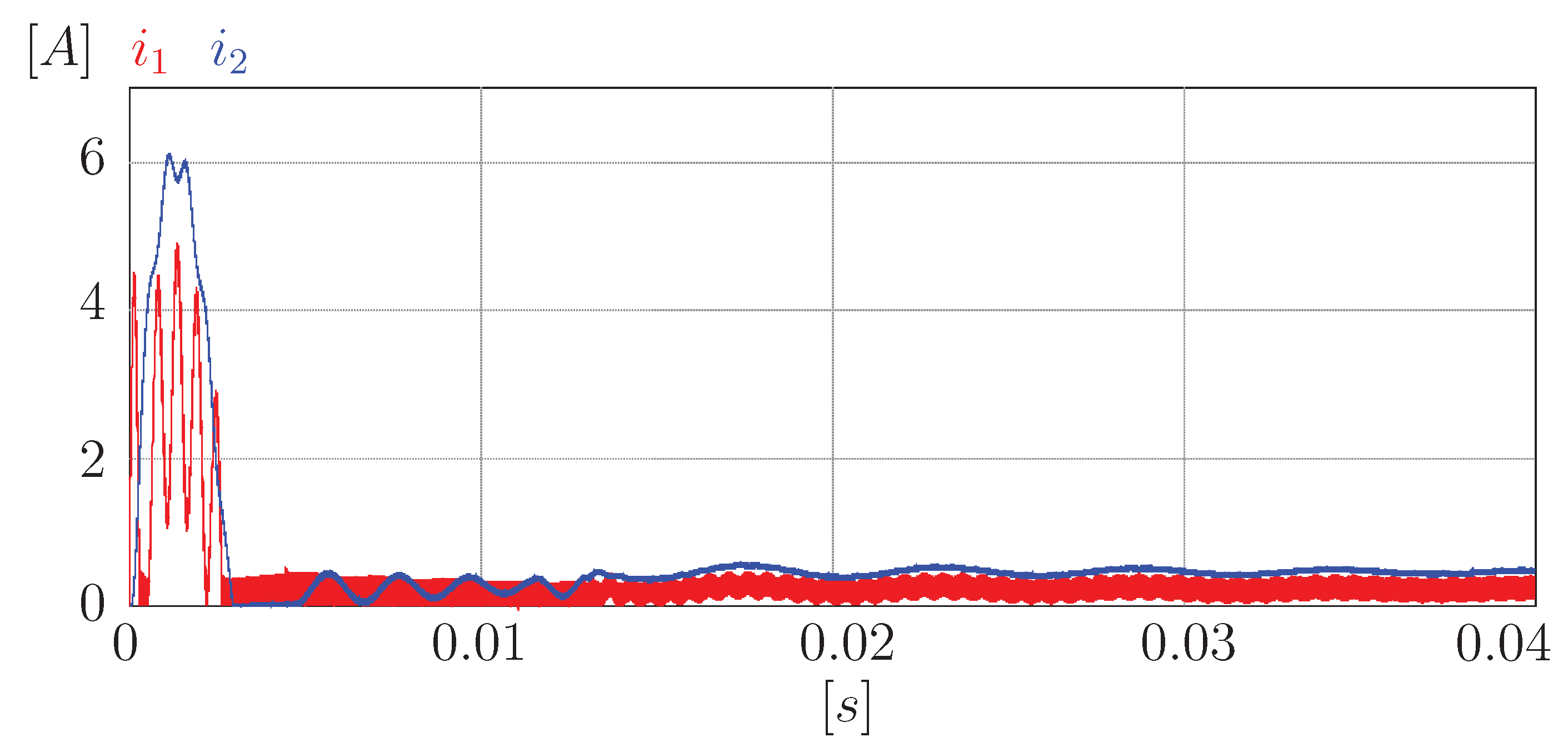
| Average steady state for (A) | 0.5 | 0.25 |
| Average steady state for (A) | 0.5 | 0.25 |
| Reaching current (A) | 6 | 6 |
| Reaching current (A) | 4 | 6 |
Disclaimer/Publisher’s Note: The statements, opinions and data contained in all publications are solely those of the individual author(s) and contributor(s) and not of MDPI and/or the editor(s). MDPI and/or the editor(s) disclaim responsibility for any injury to people or property resulting from any ideas, methods, instructions or products referred to in the content. |
© 2023 by the authors. Licensee MDPI, Basel, Switzerland. This article is an open access article distributed under the terms and conditions of the Creative Commons Attribution (CC BY) license (https://creativecommons.org/licenses/by/4.0/).
Share and Cite
Alvarez-Diazcomas, A.; Rodríguez-Reséndiz, J.; Carrillo-Serrano, R.V.; Estévez-Bén, A.A.; Álvarez-Alvarado, J.M. A Critical Comparison of the Cuk and the Sheppard–Taylor Converter. World Electr. Veh. J. 2023, 14, 148. https://doi.org/10.3390/wevj14060148
Alvarez-Diazcomas A, Rodríguez-Reséndiz J, Carrillo-Serrano RV, Estévez-Bén AA, Álvarez-Alvarado JM. A Critical Comparison of the Cuk and the Sheppard–Taylor Converter. World Electric Vehicle Journal. 2023; 14(6):148. https://doi.org/10.3390/wevj14060148
Chicago/Turabian StyleAlvarez-Diazcomas, Alfredo, Juvenal Rodríguez-Reséndiz, Roberto V. Carrillo-Serrano, Adyr A. Estévez-Bén, and José Manuel Álvarez-Alvarado. 2023. "A Critical Comparison of the Cuk and the Sheppard–Taylor Converter" World Electric Vehicle Journal 14, no. 6: 148. https://doi.org/10.3390/wevj14060148