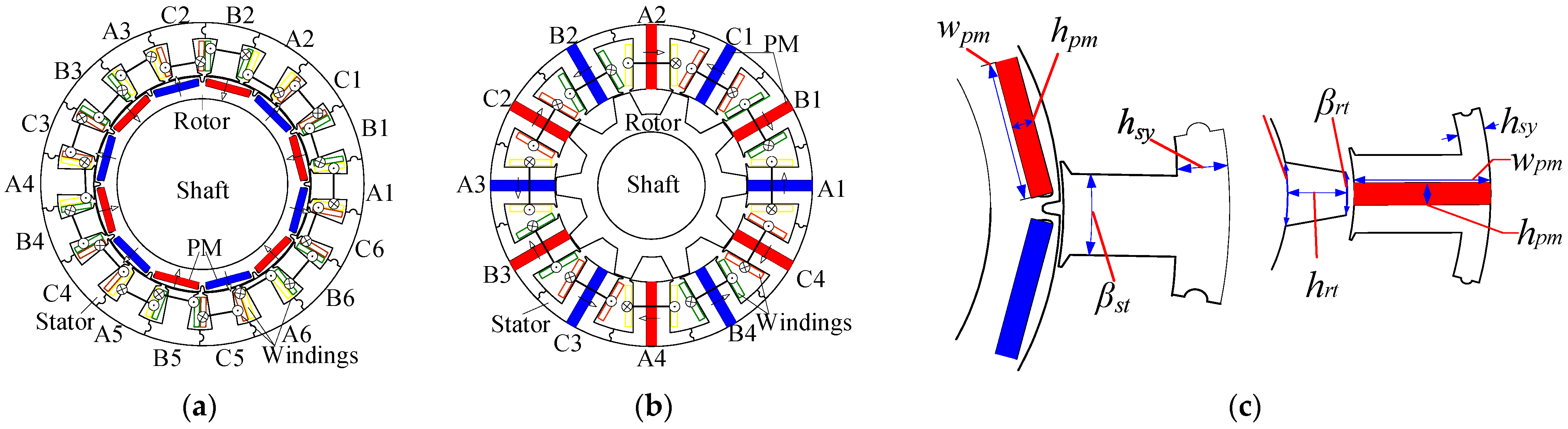
Figure 1.
Topologies of the IPM machine and the SPM-FS machine with different PM locations. (a) IPM machine, (b) SPM-FS machine, (c) modular stator elements of the IPM machine and the SPM-FS machine.
Figure 1.
Topologies of the IPM machine and the SPM-FS machine with different PM locations. (a) IPM machine, (b) SPM-FS machine, (c) modular stator elements of the IPM machine and the SPM-FS machine.
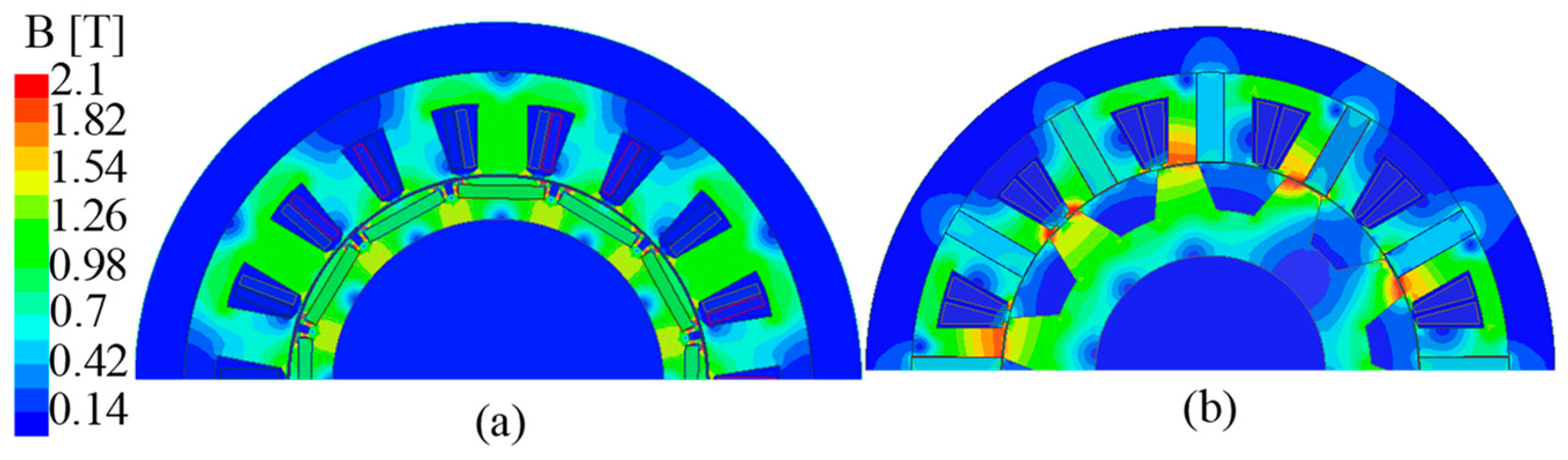
Figure 2.
No-load flux density of the two machines. (a) IPM, (b) SPM-FS.
Figure 2.
No-load flux density of the two machines. (a) IPM, (b) SPM-FS.
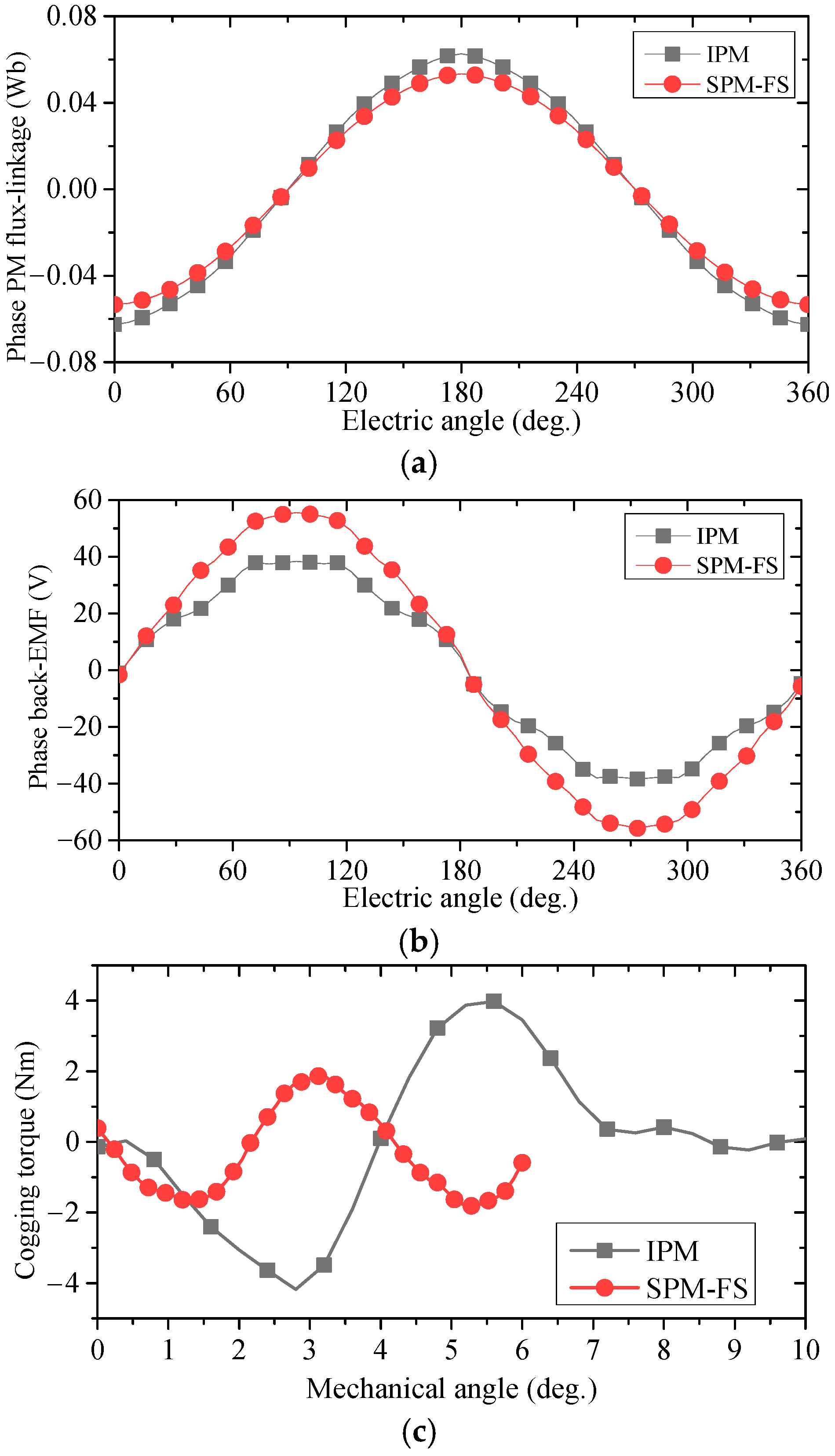
Figure 3.
PM flux-linkage, back-EMF @1000 rpm and cogging torque waveforms of the two machines. (a) PM flux-linkage, (b) back-EMF. (c) cogging torque.
Figure 3.
PM flux-linkage, back-EMF @1000 rpm and cogging torque waveforms of the two machines. (a) PM flux-linkage, (b) back-EMF. (c) cogging torque.
Figure 4.
Effect of current angle on electromagnetic torque@ 150 Arms.
Figure 4.
Effect of current angle on electromagnetic torque@ 150 Arms.
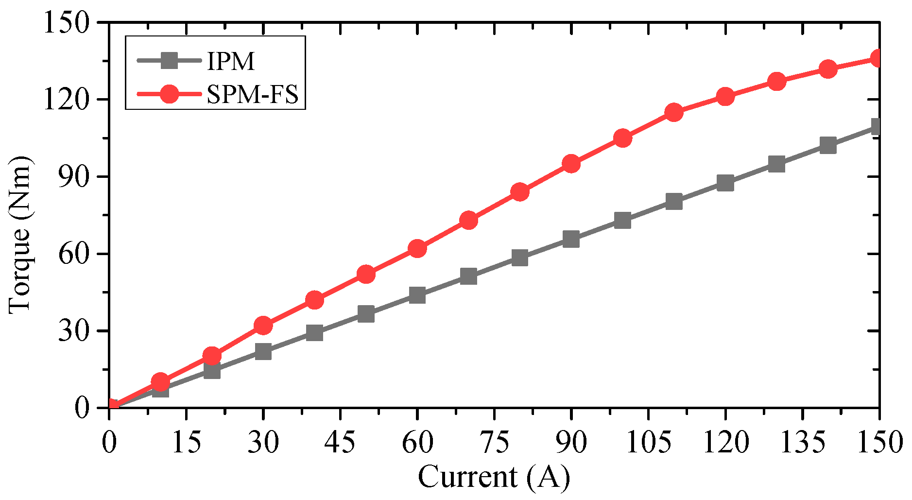
Figure 5.
Torque versus current density of the IPM and SPM-FS machines.
Figure 5.
Torque versus current density of the IPM and SPM-FS machines.
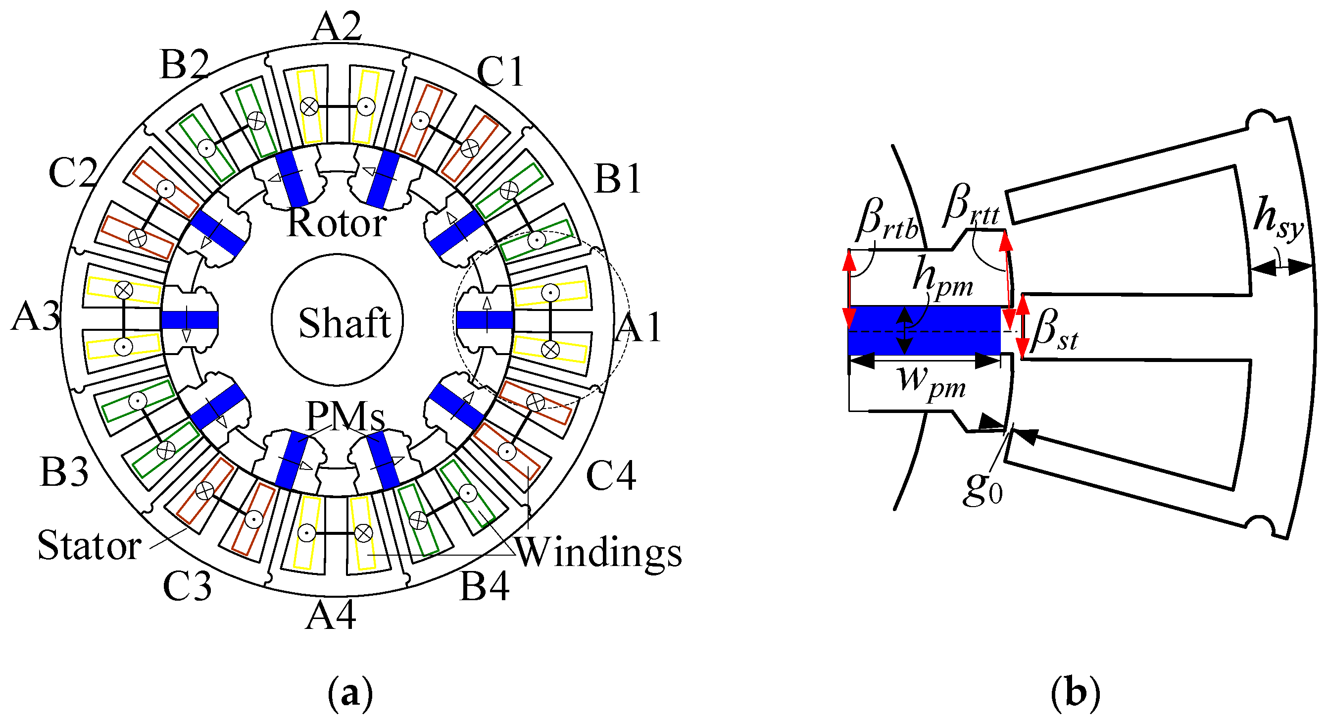
Figure 6.
The 12/10 RPM-FS machine. (a) Cross-section, (b) modular element.
Figure 6.
The 12/10 RPM-FS machine. (a) Cross-section, (b) modular element.
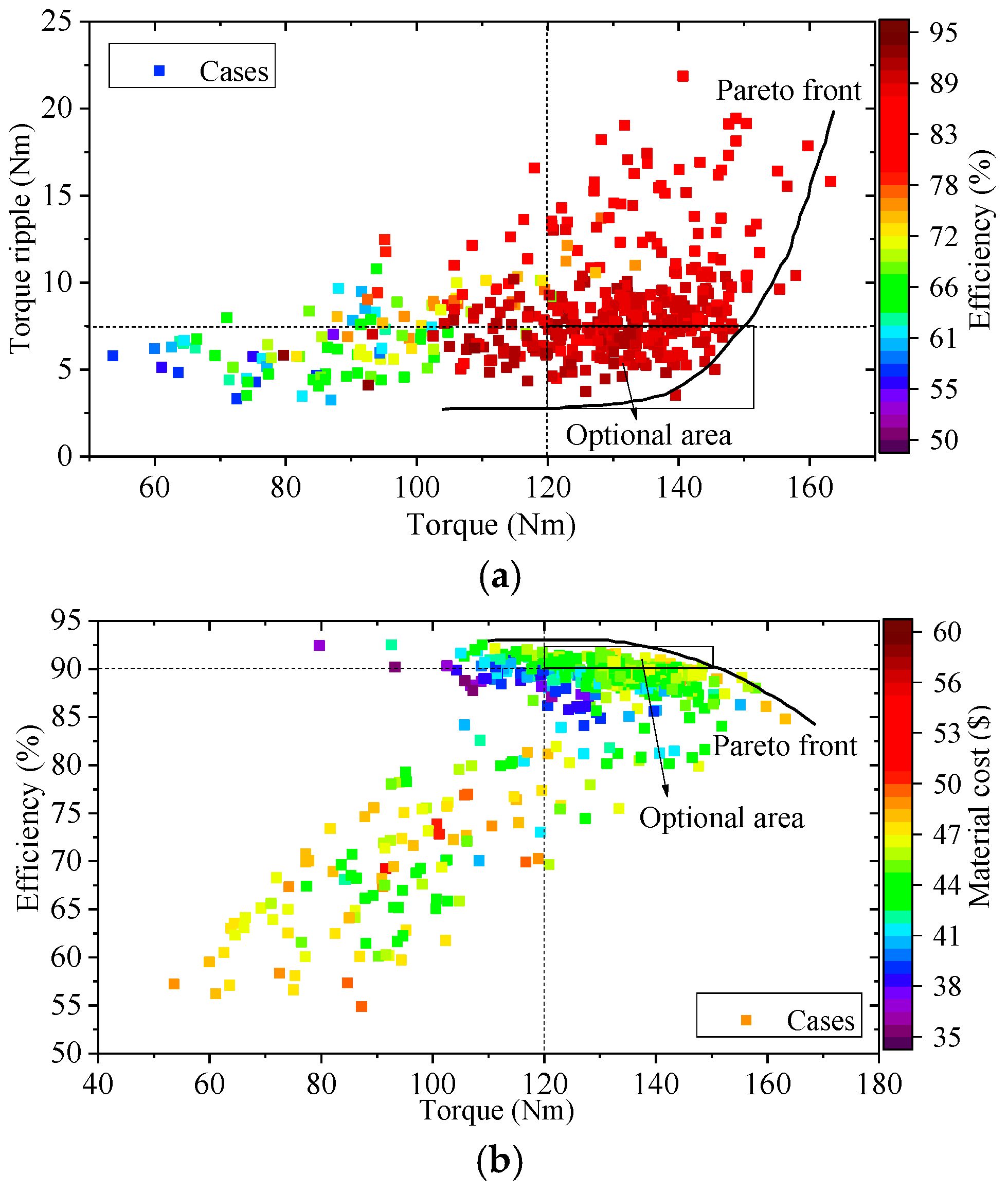
Figure 7.
Optimization results of RPM-FS machine. (a) Considering torque, torque ripple, and efficiency, (b) considering torque, efficiency and material cost.
Figure 7.
Optimization results of RPM-FS machine. (a) Considering torque, torque ripple, and efficiency, (b) considering torque, efficiency and material cost.
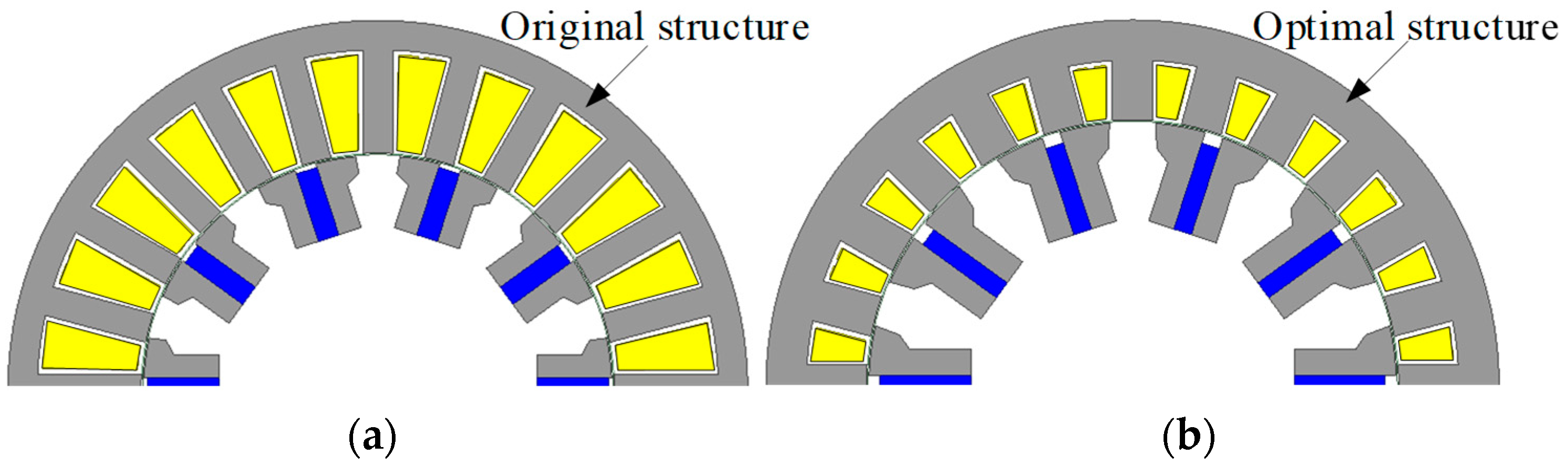
Figure 8.
The original and optimal RPM-FS machines: (a) original, (b) optimal.
Figure 8.
The original and optimal RPM-FS machines: (a) original, (b) optimal.
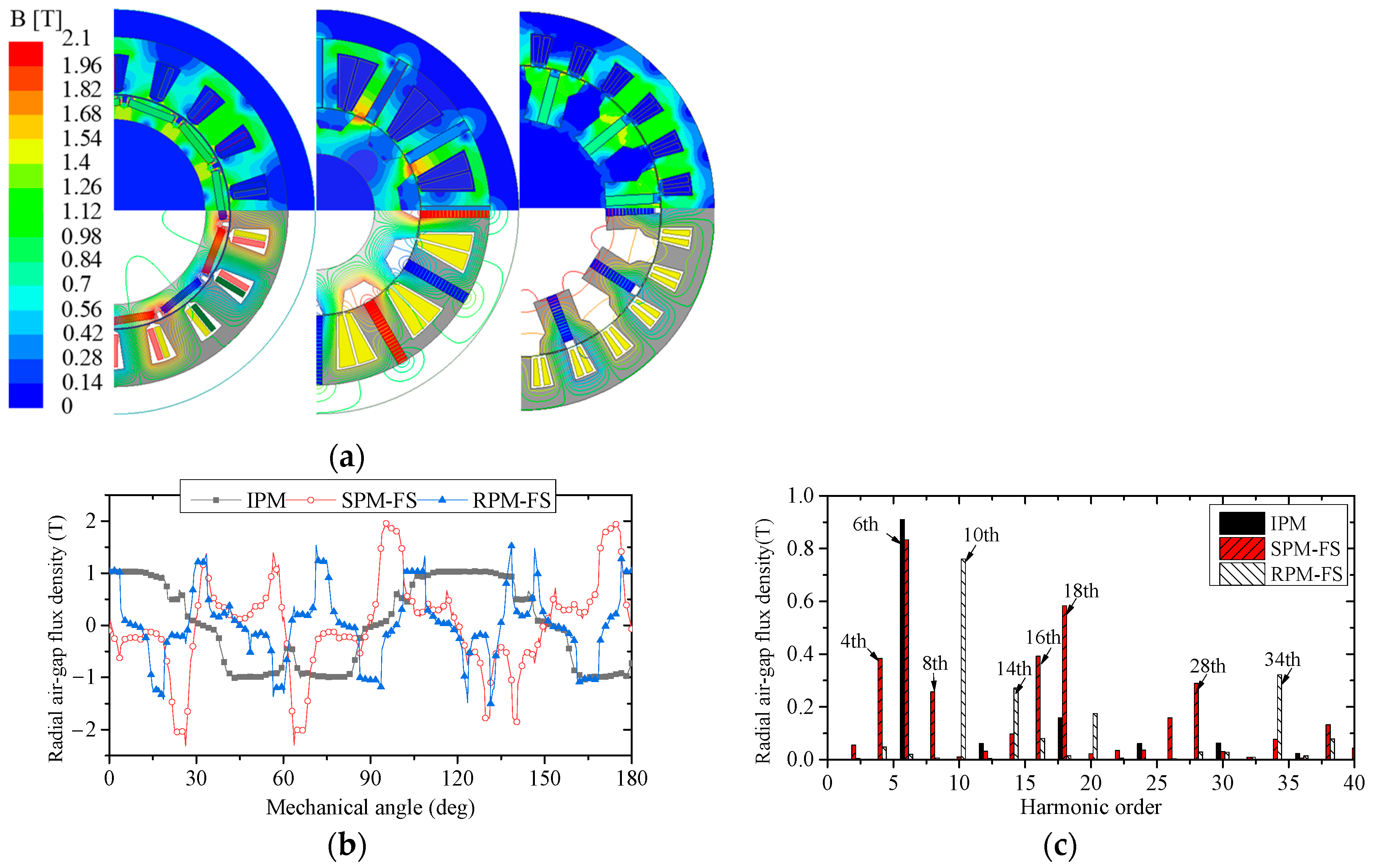
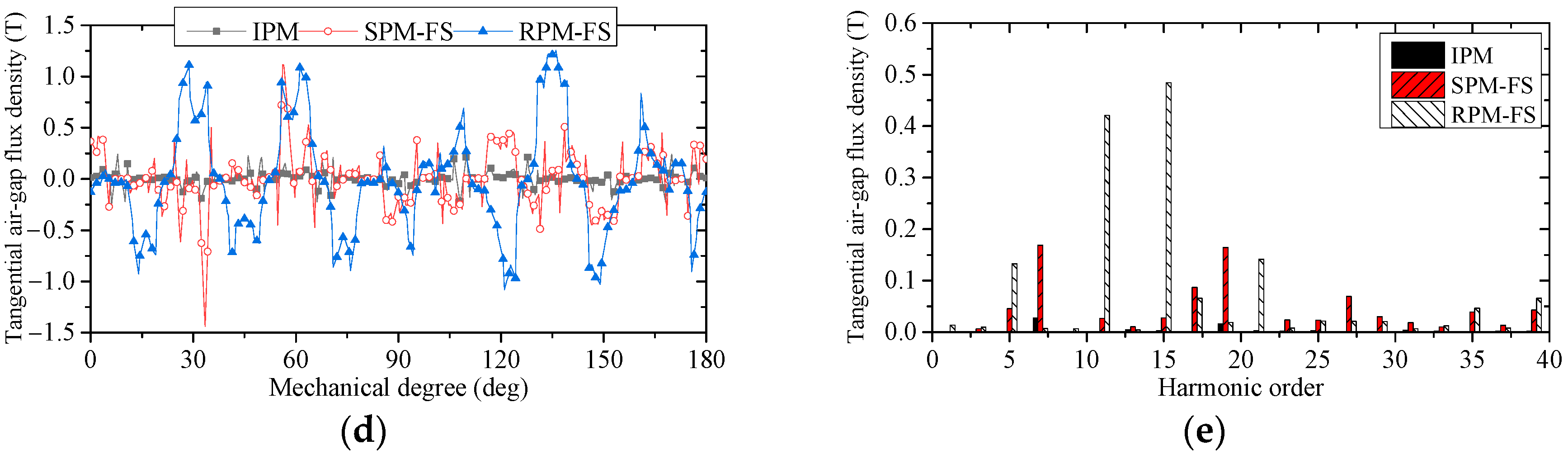
Figure 9.
Open-circuit performance of the three machines. (a) PM field distribution, (b) radial air-gap PM flux density, (c) radial air-gap PM flux density harmonic distributions, (d) tangential air-gap PM flux density, (e) tangential air-gap PM flux density harmonic distributions.
Figure 9.
Open-circuit performance of the three machines. (a) PM field distribution, (b) radial air-gap PM flux density, (c) radial air-gap PM flux density harmonic distributions, (d) tangential air-gap PM flux density, (e) tangential air-gap PM flux density harmonic distributions.
Figure 10.
Predicted cogging torque waveforms of the three machines by FEM.
Figure 10.
Predicted cogging torque waveforms of the three machines by FEM.
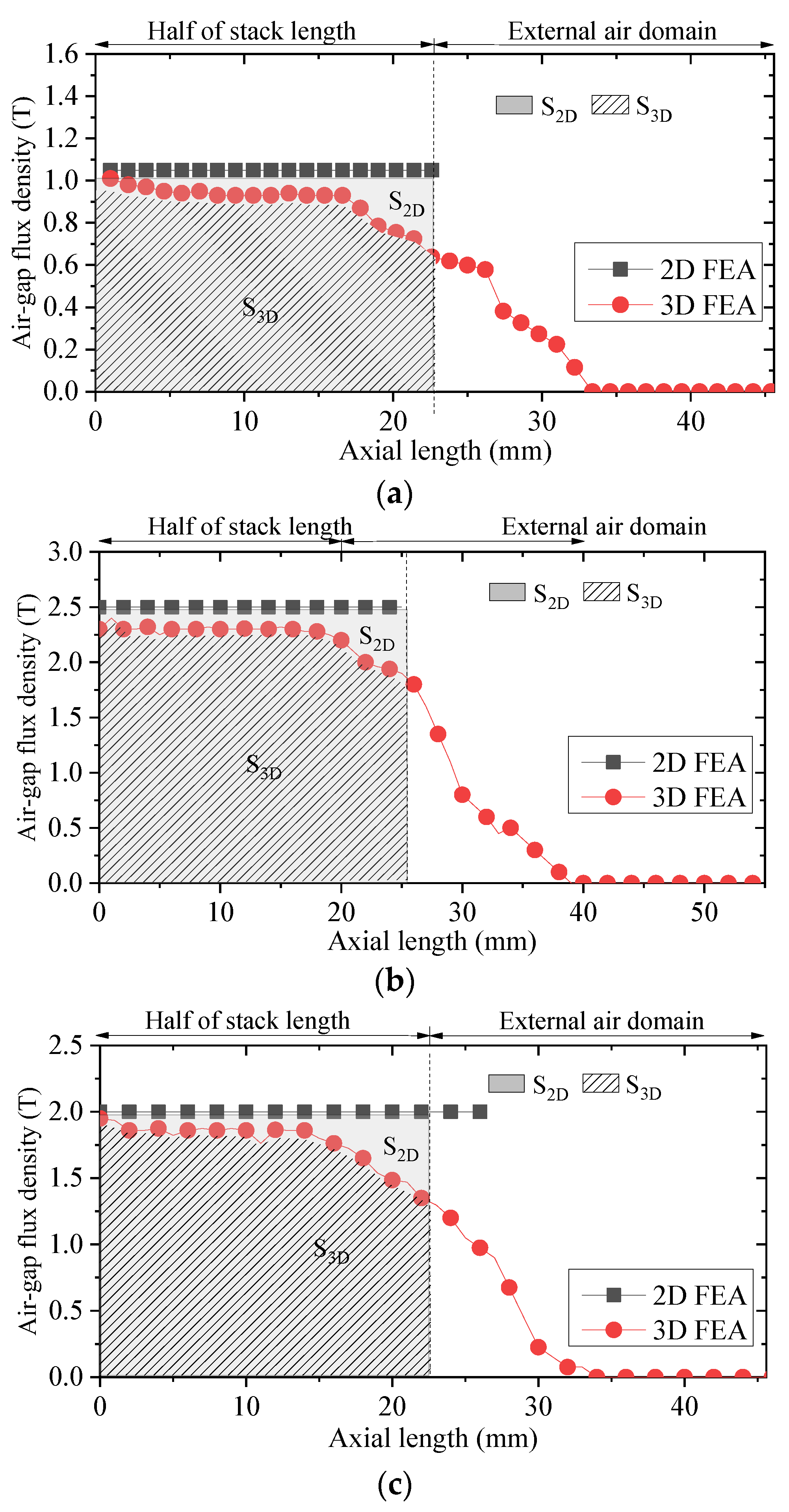
Figure 11.
Amplitude variations of air-gap PM flux density in axial direction. (a) IPM machine, (b) SPM-FS machine, (c) RPM-FS machine.
Figure 11.
Amplitude variations of air-gap PM flux density in axial direction. (a) IPM machine, (b) SPM-FS machine, (c) RPM-FS machine.
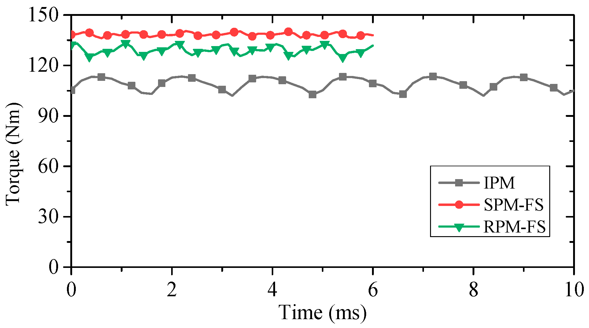
Figure 12.
Rated torque waveforms of the three machines @150Arms.
Figure 12.
Rated torque waveforms of the three machines @150Arms.
Figure 13.
Output torque versus phase current of the three machines.
Figure 13.
Output torque versus phase current of the three machines.
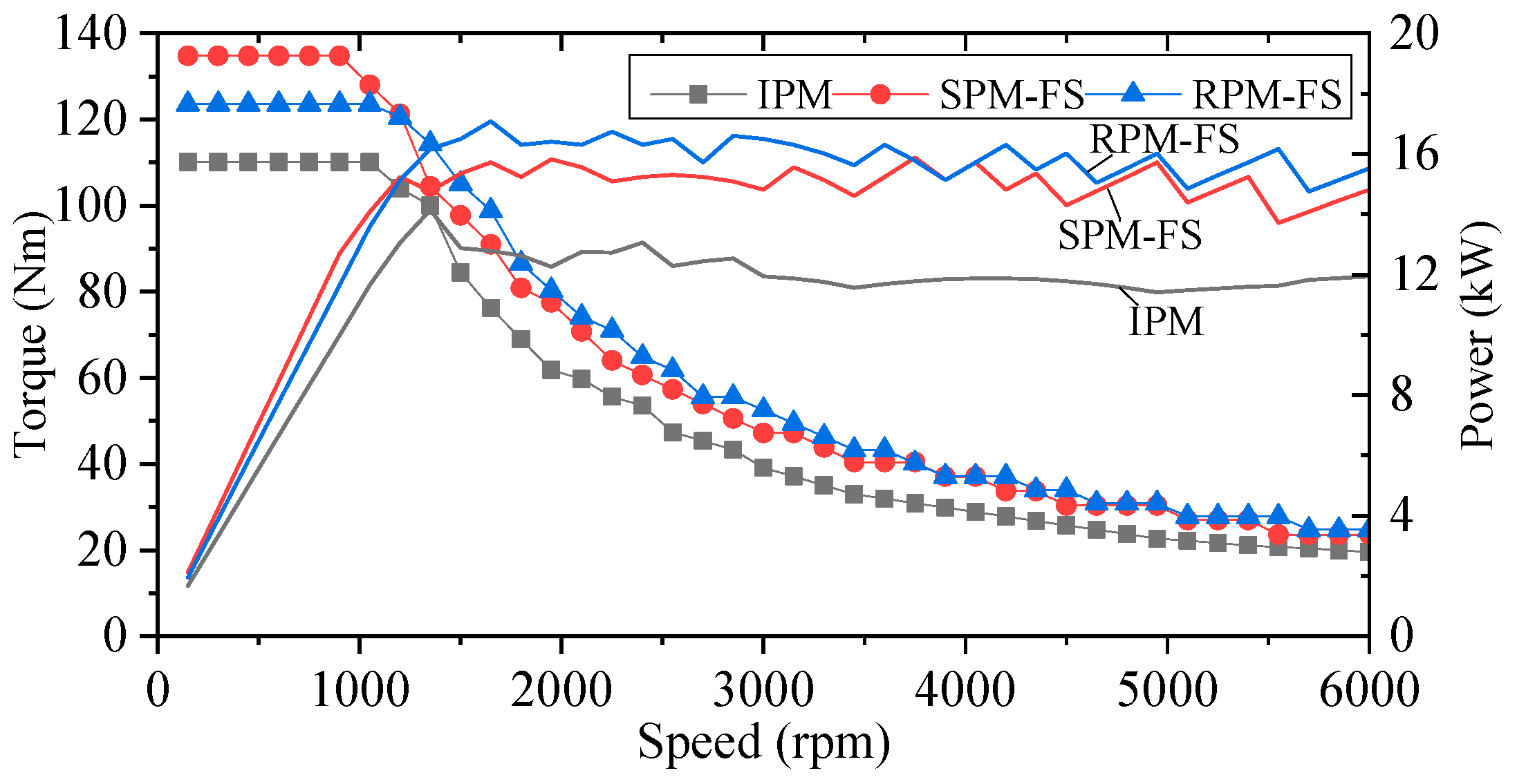
Figure 14.
Electromagnetic torque and power vs. speed of the three machines @ Udc = 158 V and Iph = 150 Arms.
Figure 14.
Electromagnetic torque and power vs. speed of the three machines @ Udc = 158 V and Iph = 150 Arms.
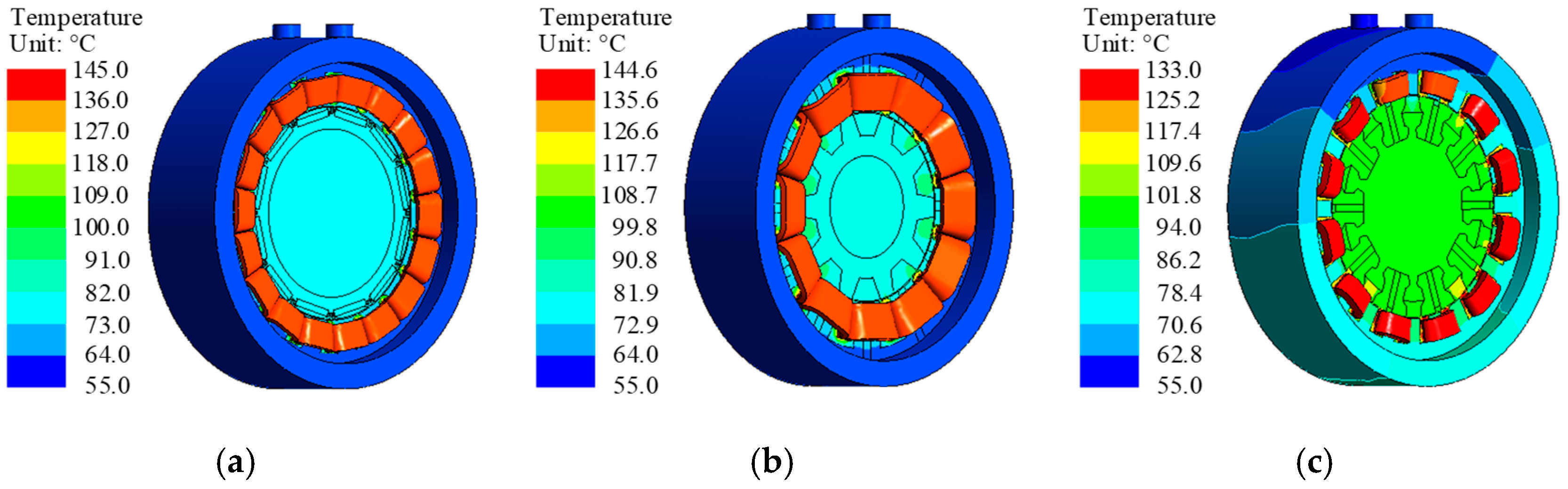
Figure 15.
Temperature distribution of the three machines. (a) IPM machine, (b) SPM-FS machine, (c) RPM-FS machine.
Figure 15.
Temperature distribution of the three machines. (a) IPM machine, (b) SPM-FS machine, (c) RPM-FS machine.
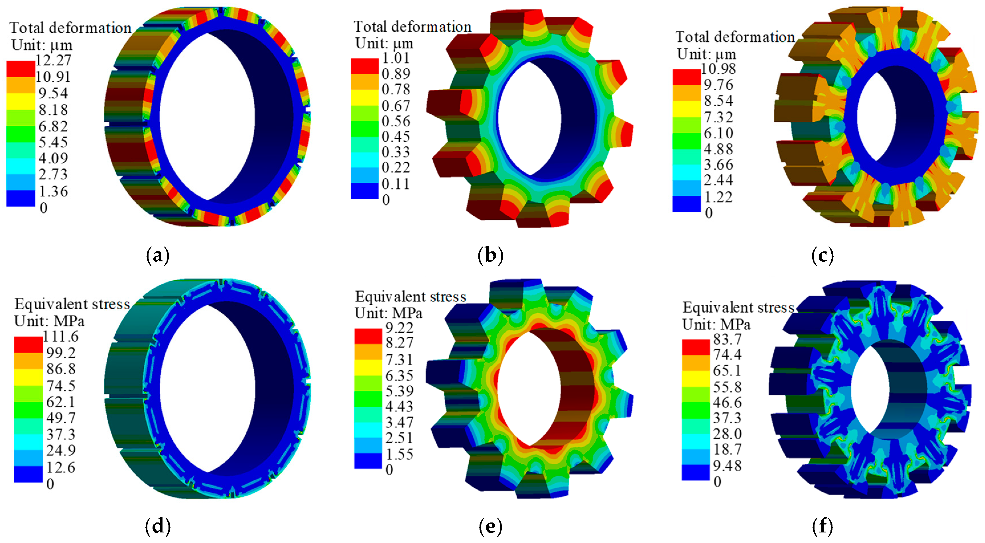
Figure 16.
Stress and deformation of the three machines. (a) IPM machine rotor, (b) SPM-FS machine rotor, (c) RPM-FS machine rotor, (d) IPM machine rotor, (e) SPM-FS machine rotor, (f) RPM-FS machine rotor.
Figure 16.
Stress and deformation of the three machines. (a) IPM machine rotor, (b) SPM-FS machine rotor, (c) RPM-FS machine rotor, (d) IPM machine rotor, (e) SPM-FS machine rotor, (f) RPM-FS machine rotor.
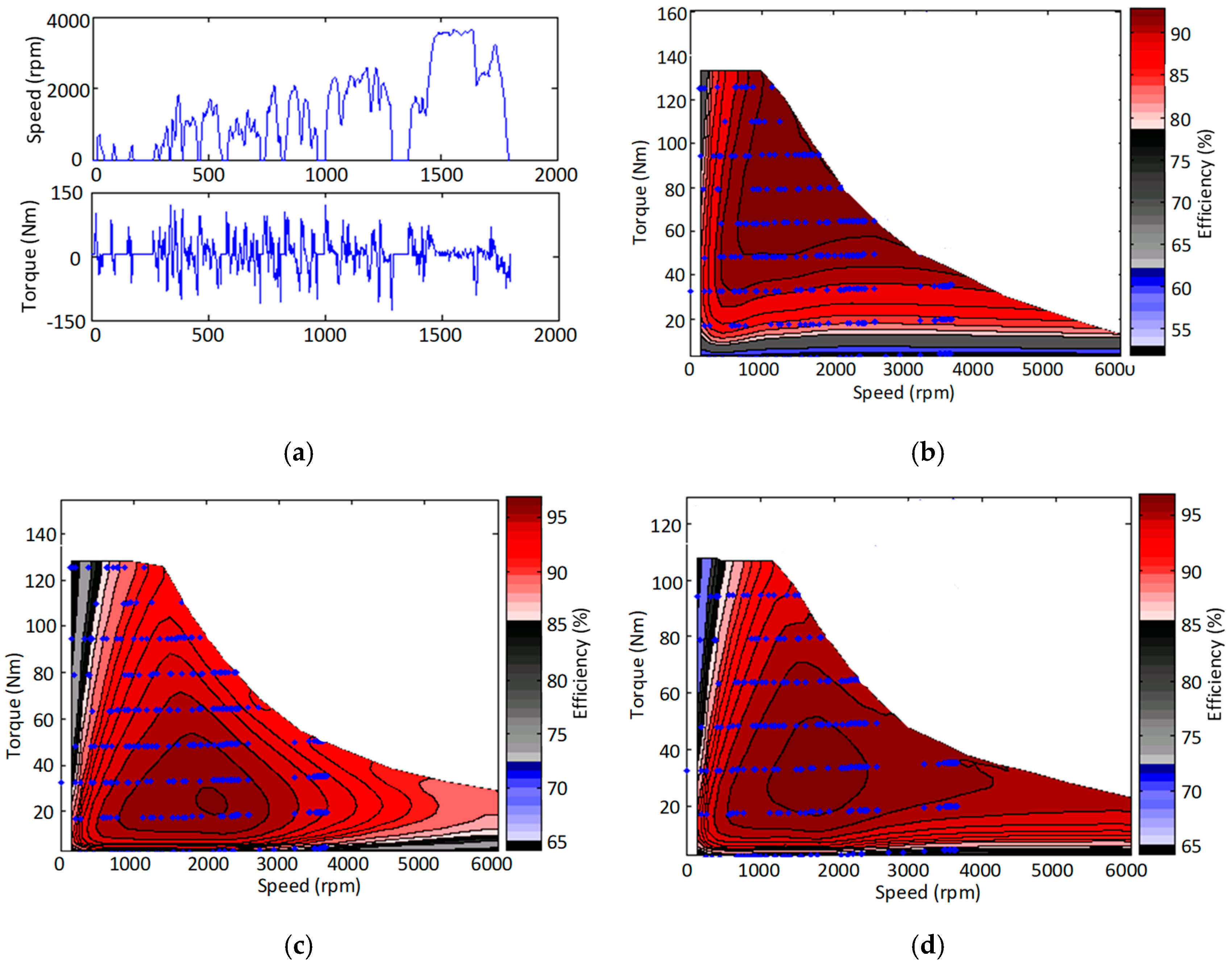
Figure 17.
Comprehensive efficiency based on cycle conditions. (a) CLTC drive cycle, (b) SPM-FS machine, (c) RPM-FS machine, (d) IPM machine.
Figure 17.
Comprehensive efficiency based on cycle conditions. (a) CLTC drive cycle, (b) SPM-FS machine, (c) RPM-FS machine, (d) IPM machine.
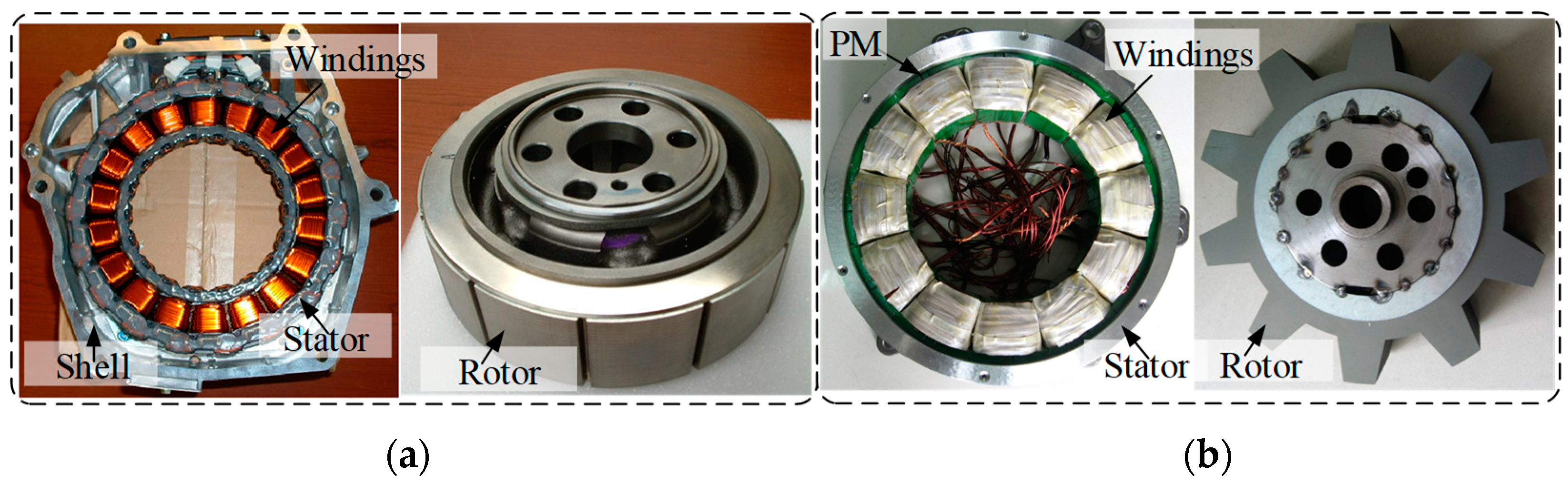
Figure 18.
The two experimental machines. (
a) IPM machine [
24,
25,
26], (
b) SPM-FS machine.
Figure 18.
The two experimental machines. (
a) IPM machine [
24,
25,
26], (
b) SPM-FS machine.
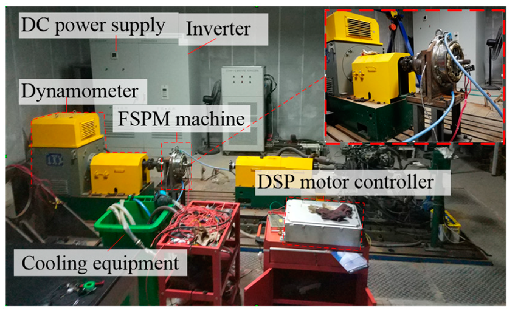
Figure 19.
Experimental platform setup.
Figure 19.
Experimental platform setup.
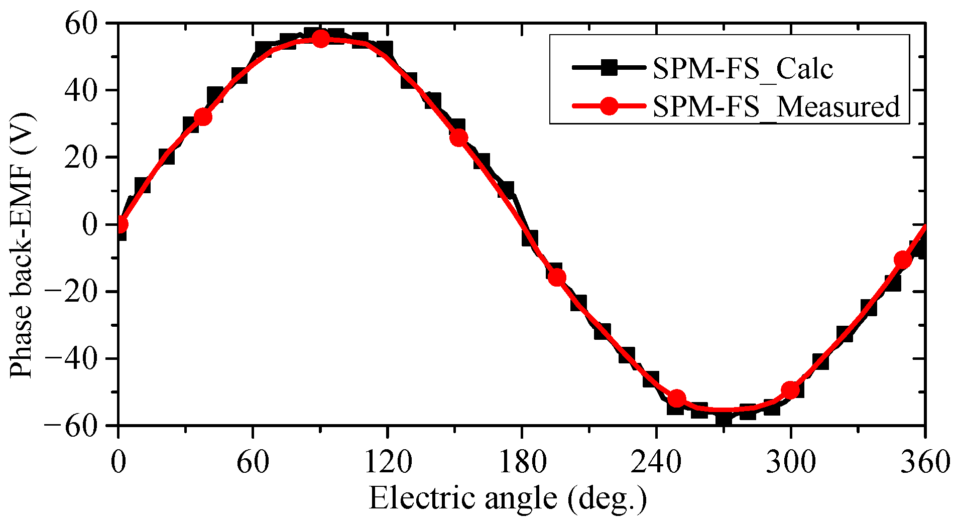
Figure 20.
Predicted and measured phase back-EMF of the SPM-FS machine @1000 rpm.
Figure 20.
Predicted and measured phase back-EMF of the SPM-FS machine @1000 rpm.
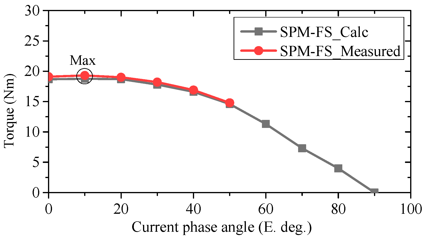
Figure 21.
Static torque vs. current angle of the SPM-FS machine @ Iph = 25 Arms.
Figure 21.
Static torque vs. current angle of the SPM-FS machine @ Iph = 25 Arms.
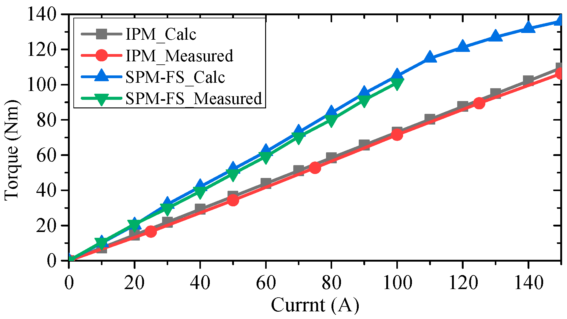
Figure 22.
Predicted and measured torque-current characteristics of the SPM-FS and IPM machines.
Figure 22.
Predicted and measured torque-current characteristics of the SPM-FS and IPM machines.
Table 1.
Design parameters of the IPM and SPM-FS machines.
Table 1.
Design parameters of the IPM and SPM-FS machines.
| Parameters | IPM | SPM-FS |
|---|
| DC-link voltage, Udc (V) | 144 | 144 |
| Base speed, nN (rpm) | 1000 | 1000 |
| Rated torque, TN (Nm) | 95.5 | 95.5 |
| Max speed, nmax (rpm) | 6000 | 6000 |
| PM remanence at 25 °C, Br (T) | 1.2 | 1.2 |
| PM coercive force at 25 °C, Hc (A/m) | −868,292 | −868,292 |
| Stator/Rotor Iron material | 35WW300 | 35WW300 |
| Stator outer diameter, Dso (mm) | 253 | 260 |
| Stack length, La (mm) | 45.6 | 55 |
| Stator slot number, Ps | 18 | 12 |
| Rotor pole number, Pr | 12 | 10 |
| PM pole-pair number, PPM | 6 | 6 |
| Electromagnetic pole-pair number, Pfe | 6 | 10 |
| Air-gap length, g0 (mm) | 0.9 | 0.9 |
| Stator split ratio (Dsi/Dso), ksio | 0.672 | 0.6 |
| Stator slot width, βslot (deg.) | 6.7 | 8 |
| Stator tooth width, βst (deg.) | 13.3 | 8 |
| Rotor tooth width, βrt (deg.) | / | 10.5 |
| Rotor yoke width, βrty (deg.) | / | 21 |
| Width of the magnet, wpm (mm) | 34.77 | 39 |
| Thickness of the magnet, hpm (mm) | 5.35 | 11.65 |
| Number of winding layers | 2 | 2 |
| Number of turns in series per phase | 60 | 48 |
| Number of strands | 20 | 17 |
| Number of parallel branches | 1 | 1 |
| Wire diameter, (mm) | 0.78 | 0.87 |
| Winding connection type | Y | Y |
| Magnet volume, Vpm (mm3) | 101,790 | 299,871 |
| Stator tooth width, Wst (mm) | 20.3 | 12.4 |
| Stator yoke thickness, Tsy (mm) | 12.4 | 9.5 |
| Turns number per coil, Nc | 10 | 12 |
Table 2.
Performance index of the RPM-FS machine.
Table 2.
Performance index of the RPM-FS machine.
| Performance Index | RPM-FS |
|---|
| Peak cogging torque, Tcog (Nm) | f(cog) |
| Rated torque, TN (Nm) | f(torque) |
| Rated torque ripple, Trip (%) | f(rip) |
| Material cost, ($) | f(cost) |
| Material mass, Q (kg) | f(mass) |
| Efficiency, η (%) | f(eff) |
| Loss, (W) | f(loss) |
Table 3.
Optimal variable of the RPM-FS machine.
Table 3.
Optimal variable of the RPM-FS machine.
| Optimal Variables | RPM-FS |
|---|
| Stator split ratio, (Dsi/Dso) | ksio |
| Rotor split ratio, (Rri/Rro) | krio |
| Stator tooth width factor | kst |
| Stator yoke width factor | ksy |
| Rotor tooth top width factor | krtt |
| Rotor tooth bottom width factor | krtb |
| Magnet width factor | kpmw |
| Magnet length factor | kpmh |
| Stator tooth width arc, (kst × π/Ps) | βst (deg.) |
| Stator yoke thickness, (ksy × πDsi/(4 × Ps)) | hsy (mm) |
| Magnet width, (kpmw × (Rro − Rri)) | wpm (deg.) |
| Magnet length, (Dri × sin(kpmh × π/4 × Pr)) | hpm (mm) |
| Rotor tooth top width arc, (krtt × π/Pr) | βrtt (deg.) |
Table 4.
Performance Index and Optimal Variable of the RPM-FS Machine.
Table 4.
Performance Index and Optimal Variable of the RPM-FS Machine.
| Parameters | Initial Value | Variation Range |
|---|
| ksio | 0.64 | 0.55~0.8 |
| kst | 0.96 | 0.8~1.2 |
| ksy | 1.9 | 1.8~2.4 |
| krio | 0.68 | 0.6~0.7 |
| krrb | 0.69 | 0.7~0.85 |
| krrt | 0.7 | 0.7~0.85 |
| kpmw | 0.95 | 0.8~0.98 |
| kpmh | 0.855 | 0.7~1.2 |
Table 5.
The optimization objectives and boundaries.
Table 5.
The optimization objectives and boundaries.
| Indexes | Objective | Boundaries |
|---|
| Efficiency (%) | 0.64 | 0.55~0.8 |
| Torque (Nm) | 0.96 | 0.8~1.2 |
| Cogging torque (Nm) | 1.9 | 1.8~2.4 |
| Torque ripple (Nm) | 0.68 | 0.6~0.7 |
| Material cost ($) | 0.69 | 0.7~0.85 |
| Phase current (A) | 0.7 | 0.7~0.85 |
| Current density (A/mm2) | 0.95 | 0.8~0.98 |
| Mass PM (kg) | 0.855 | 0.7~1.2 |
Table 6.
Comparison of the original and optimal RPM-FS Machines.
Table 6.
Comparison of the original and optimal RPM-FS Machines.
| Design Parameter | Initial Design | Optimal Design |
|---|
| ksio | 0.64 | 0.7464 |
| kst | 0.96 | 1.1813 |
| ksy | 1.9 | 2.3143 |
| krio | 0.68 | 0.6133 |
| krrb | 0.69 | 0.7045 |
| krrt | 0.7 | 0.7206 |
| kpmw | 0.95 | 0.8897 |
| kpmh | 0.855 | 0.7223 |
Table 7.
Comparison of the original and optimal RPM-FS Machines.
Table 7.
Comparison of the original and optimal RPM-FS Machines.
| Performance Index | Initial Design | Optimal Design |
|---|
| Cogging torque, Tcog (Nm) | 5.38 | 2.65 |
| Rated efficiency, η (%) | 90.5 | 92.1 |
| Rated torque, TN (Nm) | 93.4 | 129.1 |
| Rated torque ripple, Trip (%) | 8.9 | 6.8 |
| Cost, ($) | 48.44 | 41.42 |
Table 8.
Comparison of material masses of the three machines.
Table 8.
Comparison of material masses of the three machines.
| Parameters | IPM | SPM-FS | RPM-FS |
|---|
| Stator lamination mass (kg) | 7.19 | 6.23 | 5.9 |
| Rotor lamination mass (kg) | 2.06 | 4.98 | 2.06 |
| Copper mass (kg) | 2.56 | 2.36 | 1.45 |
| PM mass (kg) | 0.75 | 2.2 | 0.668 |
| Cost of silicon steel sheet (USD) | 13.4 | 16.3 | 11.5 |
| Cost of permanent magnets (USD) | 18.6 | 17.1 | 10.5 |
| Cost of copper (USD) | 21.75 | 63.8 | 19.4 |
| Total effective mass (kg) | 12.6 | 15.77 | 10.07 |
| Maximum power (kW) | 14.1 | 15.8 | 16.7 |


