Article

Critical Performance Analysis of Four-Wheel Drive Hybrid Electric Vehicles Subjected to Dynamic Operating Conditions

by
Darsy John Pradeep
1,
Yellapragada Venkata Pavan Kumar
1,*,
Bollineni Raja Siddharth
1,
Challa Pradeep Reddy
2,
Mohammad Amir
3 and
Haris M. Khalid
4,5,6,*
1
School of Electronics Engineering, VIT-AP University, Amaravati 522237, Andhra Pradesh, India
2
School of Computer Science and Engineering, VIT-AP University, Amaravati 522237, Andhra Pradesh, India
3
Department of Electrical Engineering, Jamia Millia Islamia Central University, New Delhi 110025, India
4
College of Engineering and Information Technology, University of Dubai, Academic City Emirates Road, Dubai 14143, United Arab Emirates
5
Department of Electrical and Electronic Engineering Science, University of Johannesburg, Auckland Park 2006, South Africa
6
Department of Electrical Engineering, University of Santiago, Santiago 3363, RM, Chile
*
Authors to whom correspondence should be addressed.
World Electr. Veh. J. 2023, 14(6), 138; https://doi.org/10.3390/wevj14060138
Submission received: 11 April 2023 / Revised: 23 May 2023 / Accepted: 24 May 2023 / Published: 26 May 2023

Abstract

:
Hybrid electric vehicle technology (HEVT) is emerging as a reliable alternative to reduce the constraints of battery-only driven pure electric vehicles (EVs). HVET utilizes an electric motor as well as an internal combustion engine for its operation. These components would work on battery power and fossil fuels, respectively, as a source of energy for vehicle mobility. The power is delivered either from battery or fuel or both sources based on user requirements, road conditions, etc. HEVT uses three major propelling systems, namely, front-wheel drive (FWD), rear-wheel drive (RWD), and four-wheel drive (4WD). In these propelling systems, the 4WD model provides torque to all four wheels at the same time. It uses all four wheels to propel thereby offering better driving capability, better traction, and a strong grip on the surface. The 4WD-based HEVs comprise four architectures, namely, series, parallel, series-parallel, and complex. The literature focuses primarily on any one type of architecture for analysis in the context of component optimization, fuel reduction, and energy management. However, a focus on dynamic analysis that gives a real performance insight was not conducted, which is the main motivation for this paper. The proposed work provides an extensive critical performance analysis of all four 4WD architectures subjected to various dynamic operating conditions (continuous, pulse, and step-up accelerations). Under these conditions, various performance parameters such as speed (of vehicle, engine, and motor), power (of engine and battery), battery electrical losses, charge patterns, and fuel consumption are measured and compared. Further, the 4WD architecture performance is validated with FWD and RWD architectures. From MATLAB/Simulink-based evaluation, 4WD HEV architectures have shown superior performance in most of the cases when compared to FWD type and RWD type HEVs. Moreover, 4WD parallel HEV architecture has shown superior performance compared to 4WD series, 4WD series-parallel, and 4WD complex architectures.

1. Introduction

Vehicular technology has improved and enhanced remarkably from the era of the early centuries to the modern day [1,2]. The evolution of advanced technology led to the inclusion of many new features in the process of transportation [3,4]. This is due to the shift towards decarbonization with the addition of variants such as renewable energy integration (REI) [5,6], vehicle-to-grid (V2G) technology systems [7,8], etc. The technology features have been incorporated to meet various requirements of customers and governments. The traditional internal combustion engine (ICE)-driven vehicles will be transformed into electric vehicles (EVs) soon. This is due to the increased environmental pollution and fossil fuel-related issues caused by ICE-type vehicles. However, the effective operation of any type of vehicle depends on its drive systems.

1.1. Driving System Review

In four-wheel vehicles, the power is supplied to the wheels from the power source through the powertrain. Two important configurations, namely, the two-wheel drive (2WD) and the four-wheel drive (4WD) are utilized, where the power generated is delivered to wheels for usage on the roads. Further, the 2WD systems possess two-sub configurations, namely, the front-wheel drive (FWD) and the rear-wheel drive (RWD). These systems are currently existing in all formations irrespective of vehicular technology (whether ICE, hybrid electric, or pure electric). All these drive systems are described as follows.
FWD Vehicles: Most general-purpose vehicles utilize the FWD configuration. This gives good fuel efficiency with the important advantage of being simple or having a less complex design. The FWD vehicles are popular over the other configurations due to their fuel efficiency and low emissions (thereby creating less pollution). Moreover, in FWD vehicles, the engine is placed on the front side of the vehicle. This is to transfer the power from the engine to the front wheels which become simple, thereby (1) reducing the complexity, (2) weight, and (3) energy loss, as long drive shafts are eliminated. Additionally, keeping the engine weight directly over the drive wheels improves acceleration and traction on slippery roads. The main drawbacks of the FWD vehicle are (1) the wear and tear of front tires and (2) the requirement for heavy acceleration to pull the body of the vehicle. Moreover, the life span of these FWD vehicles is less compared to others.
RWD Vehicles: In RWD configuration, the power produced by the engine is transferred via the drive trains through the drive shafts and finally into the wheels. The weight of the vehicle is transferred to the backside so that the immediate punch of acceleration throws the vehicle into motion. The front wheels in RWD are helpful to change the direction, while the weight at the back reduces the torque. The RWD vehicles require a driveshaft that needs to connect to the power source or engine, which is placed on the front side of the vehicle. Placing the engine at the back can lead to stability and control issues. This also makes RWD configurations use up lots of space. The additional weight and other factors make RWD cars less fuel-efficient compared to FWD vehicles. The RWDs are used in heavy vehicles such as trucks, etc. This is due to their property of traction control.
4WD Vehicles: The 4WD and all-wheel drive (AWD) systems are the systems that come under the 4WD type of systems. In these systems, all four wheels propel and offer a better driving experience under almost any road condition. The AWD system is almost like 4WD except for providing extra traction when needed. AWDs are also heavier compared to FWDs for the same power rating. Both configurations are complex when compared to 2WD vehicles and with increased weight, the fuel efficiency of the 4WD is also less compared to 2WD vehicles. The 4WD offers better traction force which is very much necessary for proper grip on the surface. Further, in places with slick, loose, or slippery surfaces, the power is directly provided to the wheels of the vehicle to have more traction force control. For driving on off-road and unconventional roads, FWD vehicles are preferred. The cost of FWD is also more despite a lesser fuel efficiency, but it is preferred by the customers as it suits most road and environmental conditions and gives a premium driving experience. The 4WD is equipped with additional gear which is used to switch the power provided to the two other wheels. These are normally called the 4 × 4 variants, mostly seen in jeeps and SUVs. The 4WD, AWD, and 6 × 4 (drivetrain) are the most popular ones which are in the present market.
On the other hand, considering the issues of battery-only driven pure EVs, the hybrid electric vehicle (HEV) is emerging as a reliable alternative. HEVs provide more driving range compared to EVs as their operation includes the use of both an electric motor (EM) and an ICE. It uses batteries, renewable energy sources, fossil fuels, etc., as sources of energy for vehicle mobility. A study conducted on 4WD HEV showed that the hybrid vehicle needs an energy management control strategy for the city road environment, intending to maintain optimal velocities for a better fuel economy [9]. Other tasks are to maintain the vehicle’s stability and increase fuel economy wherever possible while maintaining torque control [10]. The design of the hybrid 4WD system has several models that are dependent on how the energy from the ICE and EM are coupled to the transmission of the vehicle. The new developments in this 4WD HEV include the use of in-wheel motors (IWM) technology for improved dynamics, performance, and energy savings [11,12].

1.2. Energy Management Strategy Review

The research work done by different people across the world shows how the 4WD systems can be improved in several areas to produce a good output in hybrid systems. The development mainly requires (1) powertrain management and (2) energy-efficient systems in 2WD and 4WD models. This is based on the estimation of the economic and ecological characteristics of the vehicles [13]. A vehicle velocity optimization technique in the connected environment under the equivalent consumption minimization strategy (ECMS) for 4WD HEV is proposed. In this technique, a rule-based strategy is developed based on a decentralized model of predictive control in a connected HEV environment [14]. Another important thing for a 4WD vehicle is traction control. A control strategy for the same was implemented with the addition of IWMs [15]. The wheel torque control development showed that the existing steering mechanism is not good enough to provide the torque for the control in off-road conditions. Therefore, a new self-steering mechanism is introduced to improve the dynamics and to improve the reliable nature of the vehicle [16].
The usage of energy and improving ECMS for the 4WD hybrid powertrain are developed [17]. The performance was much improved when it was built with the dual-clutch transmission, which is most often used in vehicles these days [18]. With the rise of fuel prices and exhaust-driven pollution, the series-parallel 4WD HEV was tested for fuel consumption over the four different standard cycles. The test was conducted with an algorithm that was based on dynamic programming, thereby desirable results were achieved [19]. The energy-saving is very important in hybrid four-wheel drives. A new MPC method on the same with time control to reduce vehicle speed was discussed in [20]. Additionally, the fuzzy-based algorithms to achieve optimum dual-motor power supply for saving fuel and improving fuel efficiency were discussed in [21]. Series-parallel HEV is capable of switching modes as it has multiple modes to suit different driving conditions. Energy and fuel-saving algorithms were discussed for a plugin series-parallel HEV in [22,23]. Regenerative braking which is considered an advantage in HEVs also helps in generating energy [3]. The developments made in these areas show the braking system developed with hydraulic braking is more efficient as a power generator [24]. For a vehicle in terms of SUV size, safety is also an important factor that makes it move close to the consumers. The torque control system shows how the torque vectoring systems help in the rise of both safety and agility with the in-wheel motor technology [25].
A torque integration strategy developed for hybrid slip control with the help of a single motor was designed to minimize the wheel locking like the ABS technology to provide safety [26]. An innovative 4WD powertrain based on the transmotor and capable of taking or delivering mechanical energy more than the electric ratings were discussed in [27]. The algorithm that tracks the curvilinear trajectory based on the Lagrangian multiplier path to control the path trajectory of a 4WD was discussed in [28]. The electric power source of a hybrid model can be replaced with proton exchange membrane fuel cells/supercapacitors to ensure an improvement in the range for the 4WDs. Additionally, [29] describes the equal traction force distributed in the case of 4WDs. It also provides equal torque and helps in range improvement. The developments are also done to improve the dynamic stability and minimize the drivetrain power loss in HEVs [30]. These developments are not only limited to small passenger vehicles but also to a hybrid bus that uses 4 × 4 as an HEV application. This was developed to use electronic continuous variable transmission which controls the speed in city driving conditions [31].
It can be observed that the literature mentioned here shows the focus laid on the management of safety, energy, and fuel. Many optimization techniques and algorithms are developed to design a practical hybrid 4WD system. The different drive cycles and their properties are evaluated and prove that the hybrids show the best torque outputs in low range speeds and, neglecting the highway case, it gives much ride efficiency in urban conditions [32]. Further, the powertrain analysis is done with the off-road simple vehicle. It has been modified to make use of a dual motor and dual battery system which boosted the performance by 78% [33].

1.3. Contribution and Structure of the Paper

From the literature review, it is concluded that the research was mainly focused only on any one type of 4WD HEV architecture. The performance was studied with the goal of optimization in critical aspects of HEV functioning, such as fuel reduction techniques. Energy management and power optimization are other important areas of interest. Further, the performance analysis of the 2WD HEVs such as FWD HEVs and RWD HEVs was conducted [34,35]; however, a comprehensive behavioral analysis of 4WD HEVs under dynamically varying driving conditions was not reported in the literature, which is the main motivation for this present work.
In this view, this paper presents a comprehensive analysis and critical review of the dynamic performance of all 4WD HEV architectures when subjected to dynamic operating conditions. Moreover, it aims to conclude this analysis with recommendations based on the comparative analysis of 2WD and 4WD HEVs, and among different 4WD HEV architectures.
Based on the objective of this proposed study, the rest of the paper is organized as follows. Section 2 describes the four key architectures of the HEVs and their modeling aspects. Section 3 describes the system implementation for the four models discussed in Section 2. It also provides various test conditions that are executed to test the four architectures of the HEVs. Section 4 provides the results obtained under different test conditions and their corresponding discussion, followed by conclusions in Section 5.

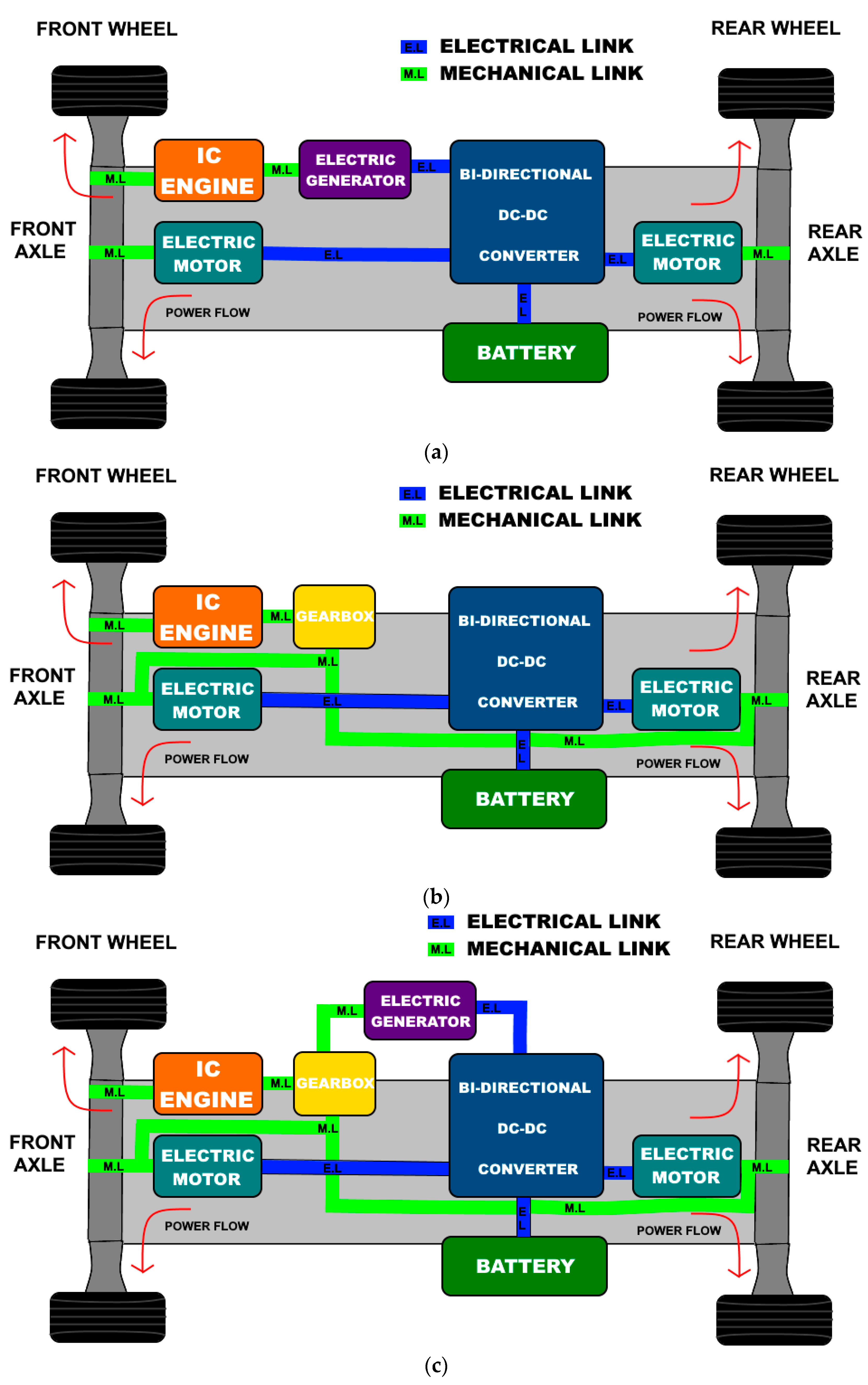
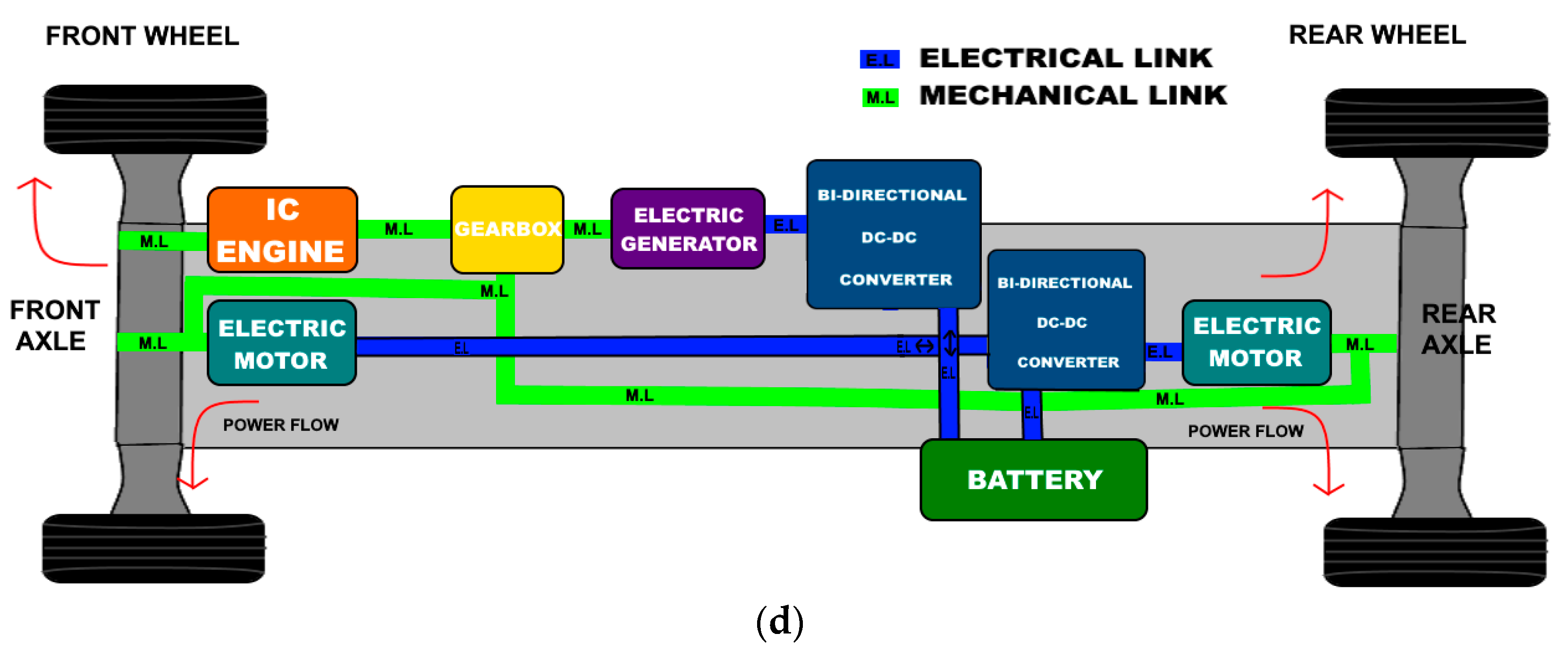
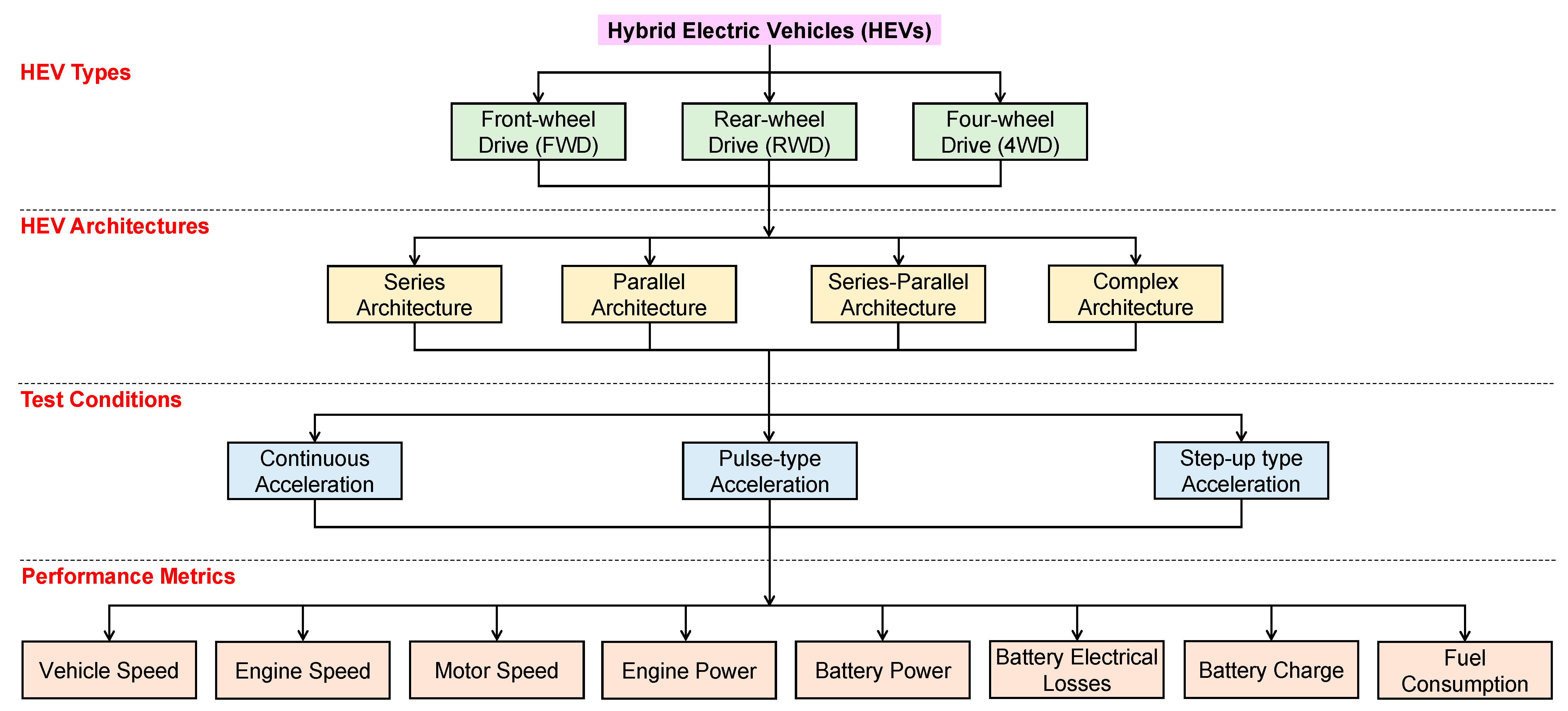
2. Description and Modelling of 4WD HEV Architectures

HEV architectures are defined based on the way ICE and EM are integrated. As shown in Figure 1, four such architectures can be built, namely, parallel architecture, series architecture, series-parallel architecture, and complex architecture. Each architecture has its virtues and limitations. These limitations are constantly persuading for development and better operation. In the present work, the above-mentioned HEV architectures were designed and probed to observe the dynamic performance.
Among the four main architectures of hybrid technology, the first and the simplest architecture is the series hybrid vehicle which is shown in Figure 1a. The name “series” is given to it because all the components are connected in a series manner to the propulsion of the vehicle. The electrical and mechanical power is in the form of a series which provides power to the powertrain and the power flow is driven into the front and rear wheels and the rear axle is equipped with an EM.
The second architecture is the parallel hybrid vehicle which is shown in Figure 1b. The name “parallel” is given to it because all the components are connected in a parallel manner to the propulsion of the vehicle. The electrical and mechanical power is parallelly provided power to the powertrain and the power flow is driven into all wheels. The third architecture is the series-parallel hybrid vehicle which is shown in Figure 1c. The name “series-parallel” is given to it because all the components are connected in a series as well as a parallel manner to the propulsion of the vehicle. The electrical and mechanical power is in the form of both combinations of series-parallel via a planetary gearbox which provides power to the powertrain and the power flow is driven into all wheels.
The fourth architecture is the complex hybrid vehicle which is shown in Figure 1d. Complex architecture is the combination of both series and parallel combinations of components. The electrical and mechanical power is in the mixed form of series and parallel which provide power to the powertrain with a dual bi-directional DC-DC converter and EM and the power flow is driven into all wheels. The building of architecture is complex, so it is named a complex hybrid.
All these hybrids are developed and designed to use the FWD system to propel the vehicle. The performance analysis of the forward-wheel drive HEV under different dynamical driving conditions is discussed in [36]. The torque distribution among the drivetrains is much more focused. A power train features (1) a source of power (EM/ICE), (2) a clutch (manual transmission) or a torque converter (automatic transmission), (3) gears, (4) a driveshaft, (5) differentials, and (6) wheels. The power distributed to the drive shaft from the power source is directly applied to the wheels through the (1) torque converter, (2) driveshaft, (3) differentials, and (4) gearbox. In a manual transmission, the clutch couples/decouples the gearbox to the engine. A torque converter in automatic transmission changes the gear ratio in a continuous variable format. The gears form the gear ratios from the input to the output shaft. It is done such that the engine speed torque matches the load. A gear pair is present in the final drive to provide additional speed and for torque distribution over the differentials to the wheels. The system modeling equations are given as follows.

2.1. Torque and Speed Calculations

The torque delivered from the source to the wheels (Twheel) is calculated using (1) and (2). The rotation speed of the wheel (Swheel) (rpm) is given by (3). The vehicle speed (Sv) is given by (4), and the vehicle’s traction force is given by (5) [36].
T w h e e l = i g r i o g η t w T o p
T o p = k 1 T i n 1 + k 2 T i n 2
S w h e e l = S o u t i g r i o r
S v = π × S w h e e l × r 30
F t r a c t i o n = T w h e e l r
where igr (=Sin/Sout) is transmission gear ratio, Sin and Sout are input and output rotating speeds, respectively, iog is the final drive’s gear ratio, ηtw is driveline efficiency of the engine to wheels, Top is output torque delivered, k1 and k2 are constants derived by torque coupling parameters, r is the wheel radius.

2.2. Fuel Calculations

To calculate average fuel consumption, the fuel consumed per 100 km distance traveled (liters/100 km) is considered. The main factors on which fuel consumption depends are (1) type of engine, (2) number of gears, (3) vehicle resistance, (4) vehicle weight, and (5) operational settings. The fuel economy of ICE is estimated as a ratio of used fuel per energy output, which is called the specific fuel consumption (gsfw) in g/kWh. To estimate the fuel economy of the vehicle, the load power of the engine and specific fuel consumption must be known. The engine load power (Peng in kW) is estimated using (6). Upon calculating engine power, the engine speed is calculated using (7). To calculate specific fuel consumption (gsfw), the plot of Seng vs. Peng is used. The time rate of fuel consumption (L/h) is calculated as per (8).
P e n g = S v η t F f + F w + F g + M v e h i c l e δ d S v d t
S e n g = 30 × S v × i g r i o r π r
Q = P e n g i n e × g s f w 1000 × γ f
where Fw—aerodynamic drag, Ff—frictional force (rolling friction), Fg—grading force, Mvehicle is the mass of the vehicle, Sv—vehicle speed, γf—fuel’s mass density (kg/L).

2.3. Power Calculations

The maximum power that a battery can give to the load is calculated in (9). The power delivered by the engine differs with respect to the vehicle’s architecture. For a vehicle employing series architecture, the power delivered is given by (10), and for parallel architecture, it is calculated by (11). The power delivered in complex architectures is given by (12).
P m a x = V o p e r 2 4 ( R c o n + R i n t e r n a l )
P e n g = S v 1000 η t η m M v e h i c l e g f r + ρ a C D A f S v 2 2
P e n g = S v 1000 η t , e M v e h i c l e g f r + 1 + S v 2 ρ a C D A f 2
P m o t o r = P t r a n s m i s s i o n P e n g = T c ω c P e n g
where Voper—battery operating voltage, Rinternal—internal resistance, Rcon—conductor resistance, fr—tire rolling resistance coefficient (=0.01), g—gravity acceleration in 9.80 m/s2, ρa—air density (=1.18 kg/m3), Af—vehicle’s front area (=3 m2), CD—aerodynamic drag coefficient (=0.4), ηt—transmission efficiency, ηm—traction motor efficiency, ηt,e—wheels transmission efficiency.

3. System Implementation and Test Conditions

The study of vehicle performance parameters under dynamic acceleration (m/s2) is crucial in determining the vehicle’s behavior and it helps in estimating future tasks. So, this section describes the various dynamic operating conditions that are implemented, the measured parameters, and the system implementation as given follows.

3.1. Dynamic Operating Conditions

HEVs performance is evaluated using the vehicle’s performance parameters for different dynamic operating conditions. Three types of inputs are applied, namely, continuous acceleration, pulse-type acceleration, and step-up type acceleration. Continuous acceleration is observed in cases where the vehicle is assumed to be operating in a no-traffic environment with good road conditions. The pulse-type acceleration is assumed to be applied in moderate to heavy traffic conditions. The sports car racing scenario is mimicked by applying step acceleration type input. So, these inputs are applied to different HEV architectures to assess their performance. The types of acceleration test inputs to which the HEVs were subjected and various parameters that are observed/computed in this study are given in Table 1.

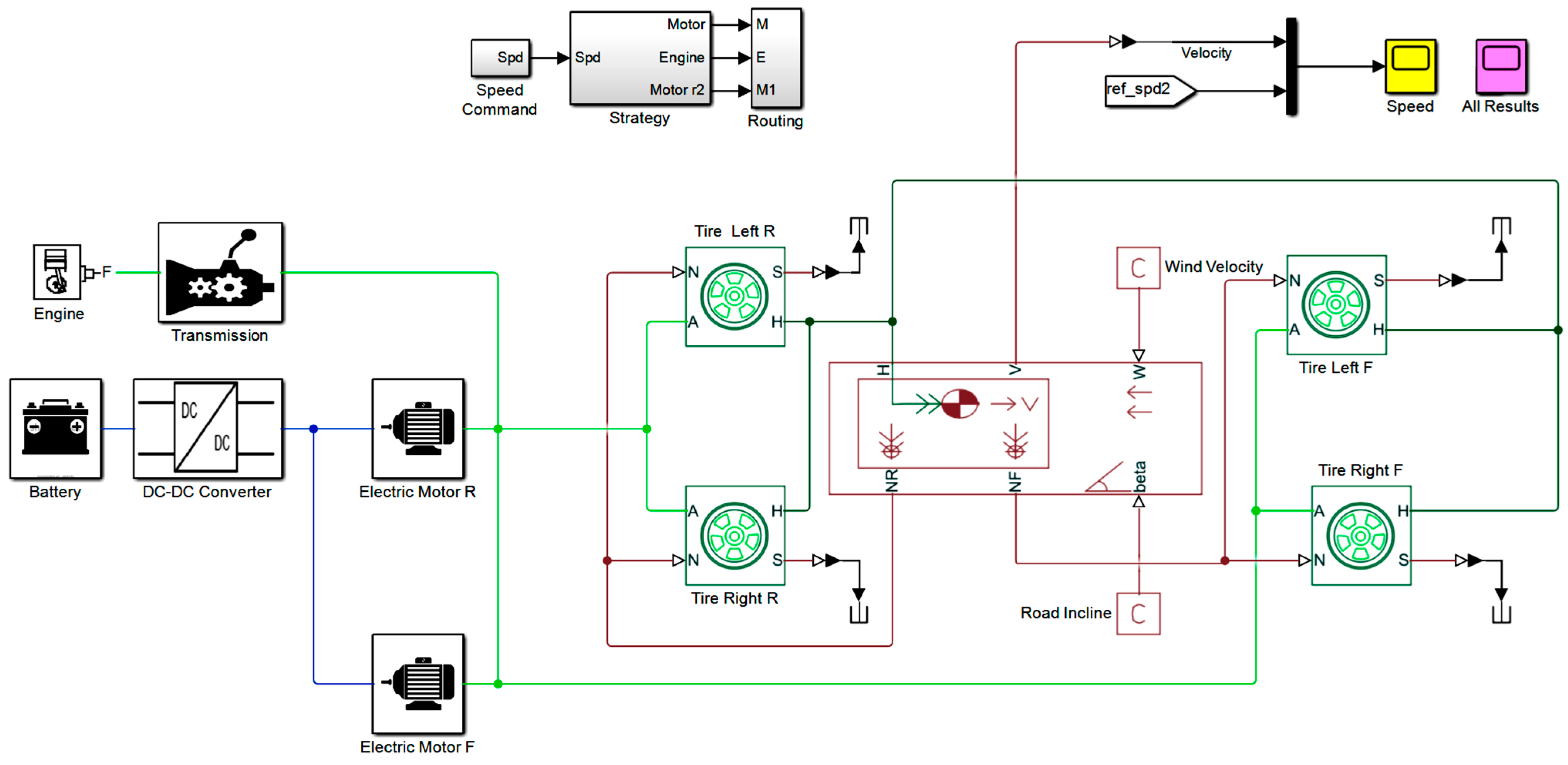
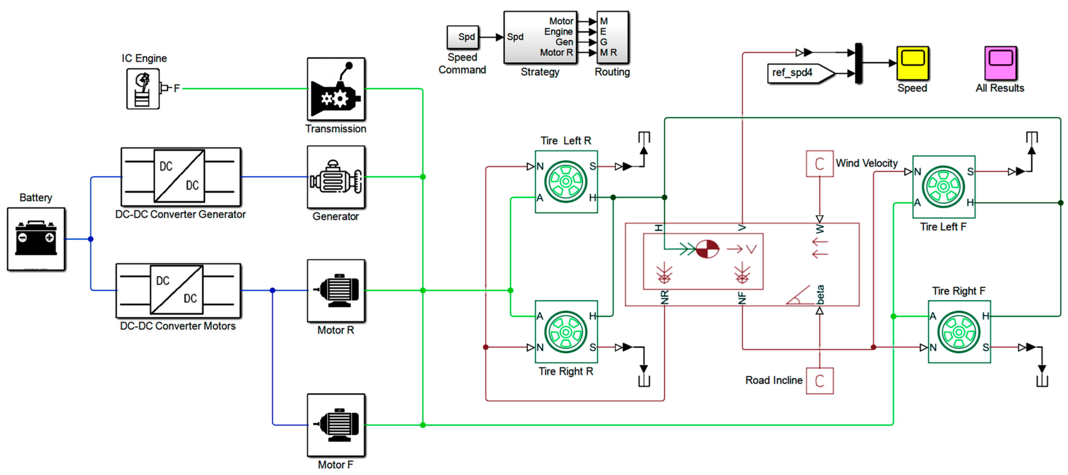
3.2. System Implementation

The Simulink models of HEV architectures mentioned in Section 2 are given in Figure 2, Figure 3, Figure 4 and Figure 5. These models are excited using three acceleration cases that mimic real-time conditions. The Simulink models are used to compute eight different performance metrics that are shown in Table 1, which helps in concluding the use of HEVs under various real-time operating conditions.
The parameters used for the system implementation are given in Table 2. The vehicle speed is an indication of how effectively the inputs affect the vehicle’s performance. The motor and engine shaft speed measurements help to determine the effect of inputs on the speed of the vehicle. The measurements of the power delivered by ICE and battery are useful to determine how the power is balanced amongst ICE and EM. The effective utilization of battery power by the HEV is determined by the battery charge parameter. The energy utilized by the battery and the unused battery power can be determined by this parameter. The way in which the battery charges and discharges following the inputs applied are also determined by the battery charge parameter. The battery loss parameter determines how much battery power is lost in the process of power conversion from the battery to the motor and also determines the charge loss. Fuel consumption is another important parameter to assess how capably the fuel is being utilized by the HEV.

4. Results and Discussion

The results of this study are presented in three subsections. The first subsection deals with the analysis of performance metrics listed in Section 3 when the HEVs are excited with test input-1. The second subsection deals with the study of performance metrics when the HEVs are excited with test input-2. A similar study is conducted and presented in the third subsection with test input-3 as excitation. The results are presented in per unit (pu) metrics on the y-axis as the comparison between different parameters with different units needs to be done. A comprehensive analysis of the performance metrics with three inputs applied to different HEV architectures is done at the end. In this study, note that the capacity of the engine, the rating of the battery, and the rating of the power converter used in all the HEV architectures are the same. The simulation is conducted for 45 s with the application of various abovementioned inputs. The results obtained for all four HEV architectures with different test inputs are compared as described follows.

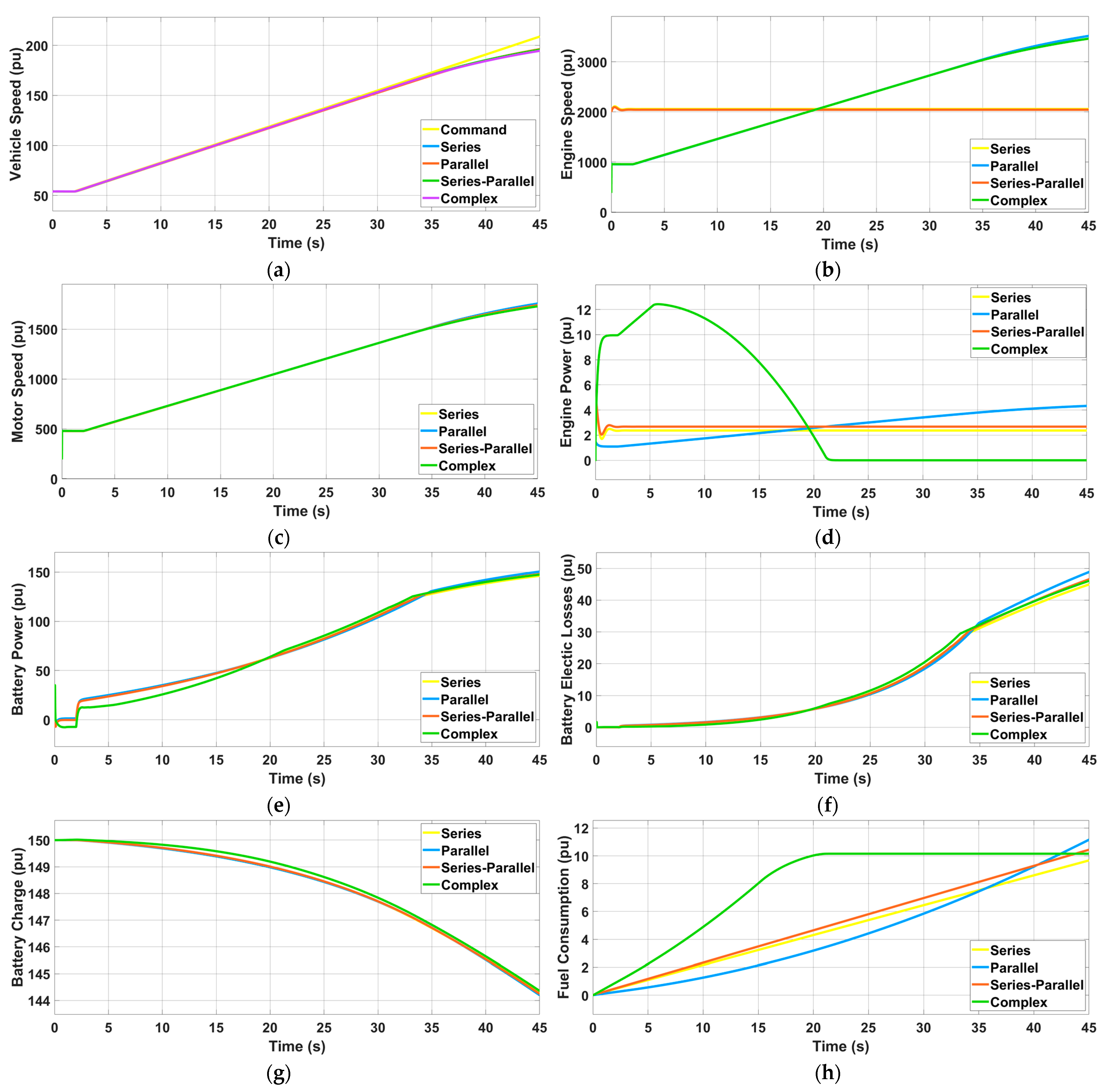
4.1. HEV Performance Parameters for Test Input-1

The plot of speeds of different HEVs when excited with test input-1 is given in Figure 6a. It can be observed that, with a change in input, there is almost a spontaneous change in the speed of all the HEV architectures. The rate of change of speed (pu) is the same in all architectures with 195 units, but the slightly parallel architecture performed well with some high speeds than others at the initial stage. The engine speed profiles of HEV architectures, when excited with test input-1, are given in Figure 6b. From this, it can be observed that the parallel and complex and the series and series-parallel were almost the same and the most performed was the complex architecture at the initial stage, but the series was superior. The motor speed profiles of all the HEV architectures excited with test input-1 are given in Figure 6c. From this, it can be observed that the responses were the same for all the architectures and the response of the complex architecture was lesser when compared to others. The engine power profiles of HEV architectures, when excited with test input-1, are given in Figure 6d. From the responses, it has been observed that the response of the parallel architecture was superior due to the low usage of the engine, followed by series architecture.
The power profiles of the battery used in different HEVs when excited by test input-1 are given in Figure 6e. From the plot, it is observed that the parallel architecture used more battery power so it is superior. Battery electric loss profiles of different HEV architectures, when excited with test input-1, are given in Figure 6f. The parallel architecture shows the least loss whereas the complex architecture presents a higher loss. The state of the battery charge for different HEV architectures, when excited with test input-1, is given in Figure 6g. From the profiles, it is noted that the complex architecture has kept the initial value and charged 0.8 units in other architectures; this decrement is 0.9 pu. With the increasing cost of fuel, fuel consumption has become a key factor that needs to be studied. The fuel consumption pattern of various HEV architectures, when excited with test input-1, is plotted in Figure 6h. From these results, it is seen that the series architecture is the most fuel-efficient and the parallel architecture is the least fuel-efficient among all the architectures studied.

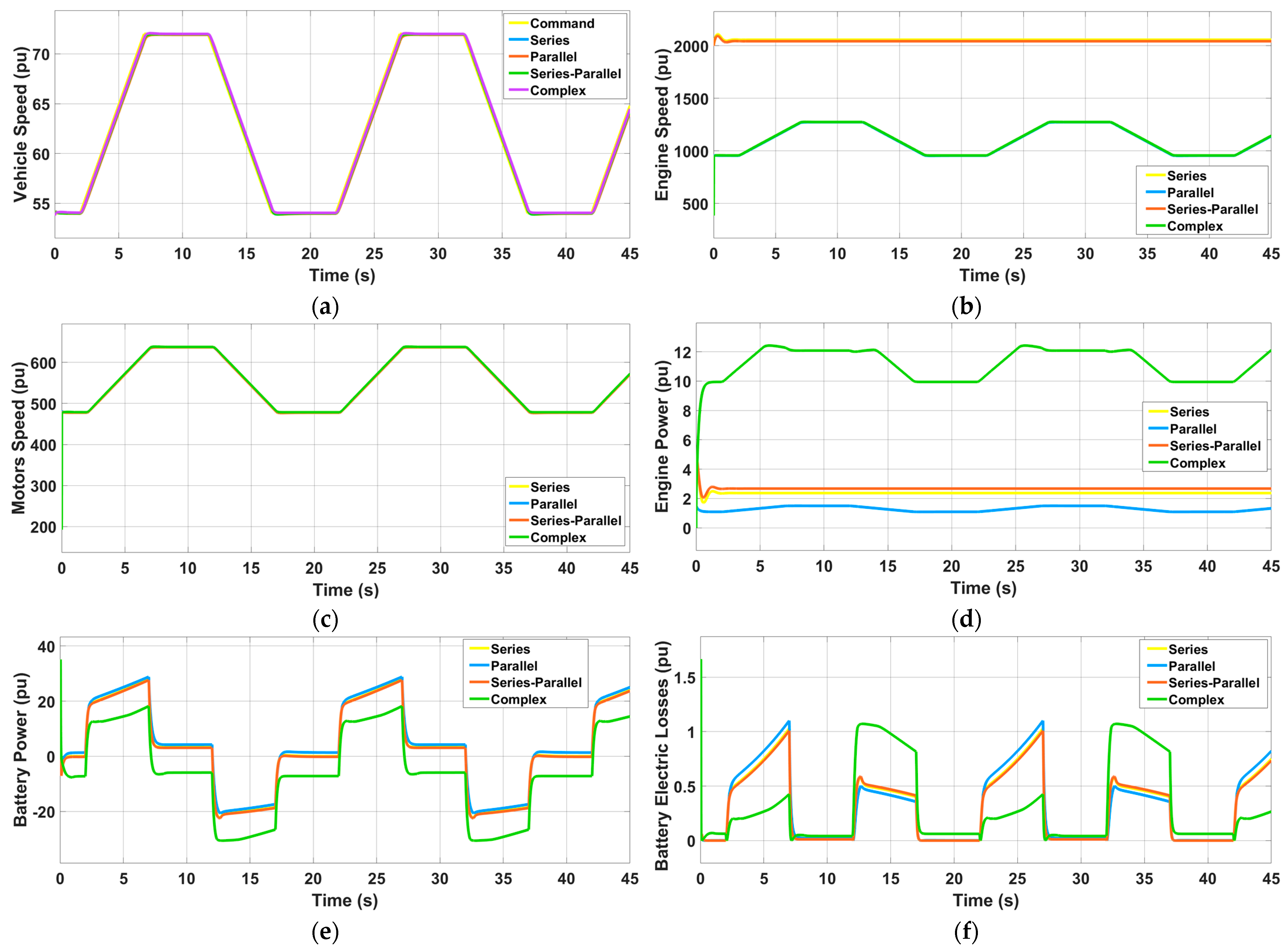
4.2. HEV Performance Parameters for Test Input-2

In lesser and mid-range traffic regions, pulse-type acceleration is preferably applied to tackle traffic uncertainties. Analysis and effects of these inputs on HEV performance are of major interest in the proposed work. The performance of the HEV architecture is analyzed by providing a pulse for 5 s and studying fall time and rise time. The input is applied for 45 s in two continuous cycles to study the effect of pulse-type acceleration on various HEV architectures. Various performance parameters of the HEV for test input-2 are given in Figure 7.
The plots of speeds for different HEV architectures with test input-2 applied are given in Figure 7a. From the figure, it can be perceived that the response of three HEV architectures is approximately 71 units, but for complex HEV architecture, the speed is approximately 72 units. The engine speed profiles of HEV architectures, when excited with test input-2, are given in Figure 7b. From the response, it is observed that the series architecture performance was superior, followed by the series-parallel architecture.
The motor speed profiles of HEV architectures for this input are given in Figure 7c. From the response, it can be noted that the performance of parallel HEV architecture is superior compared to the performance of other architectures. The engine power profiles for test input-2 are given in Figure 7d. It is observed that the performance of the parallel architecture is superior in terms of lower engine power utilization. The profiles of battery power for test input-2 for all the HEV architectures are given in Figure 7e. The parallel architecture showed a superior performance whereas the complex architecture is seen to utilize less battery power.
The loss profiles of battery power of HEV architectures for test input-2 are given in Figure 7f. The least power loss is experienced in the series-parallel architecture whereas complex architecture experience higher loss. For a pulsated acceleration, the charge profiles of the battery for various HEV architectures are given in Figure 7g. The charging and discharging profiles for pulse input of the HEV architectures follow the same pattern of decrement with respect to time except for the complex HEV architecture where the battery charge has improved in terms of time. As the battery discharge is improved with respect to time in the complex HEV architecture, it is considered the superior architecture with respect to battery charge for a pulse input.
The fuel consumption profiles of various HEV architectures for test input-2 are given in Figure 7h. From the responses, it is observed that complex architectures consume more fuel when compared to other architectures and parallel architecture consumes the least fuel.

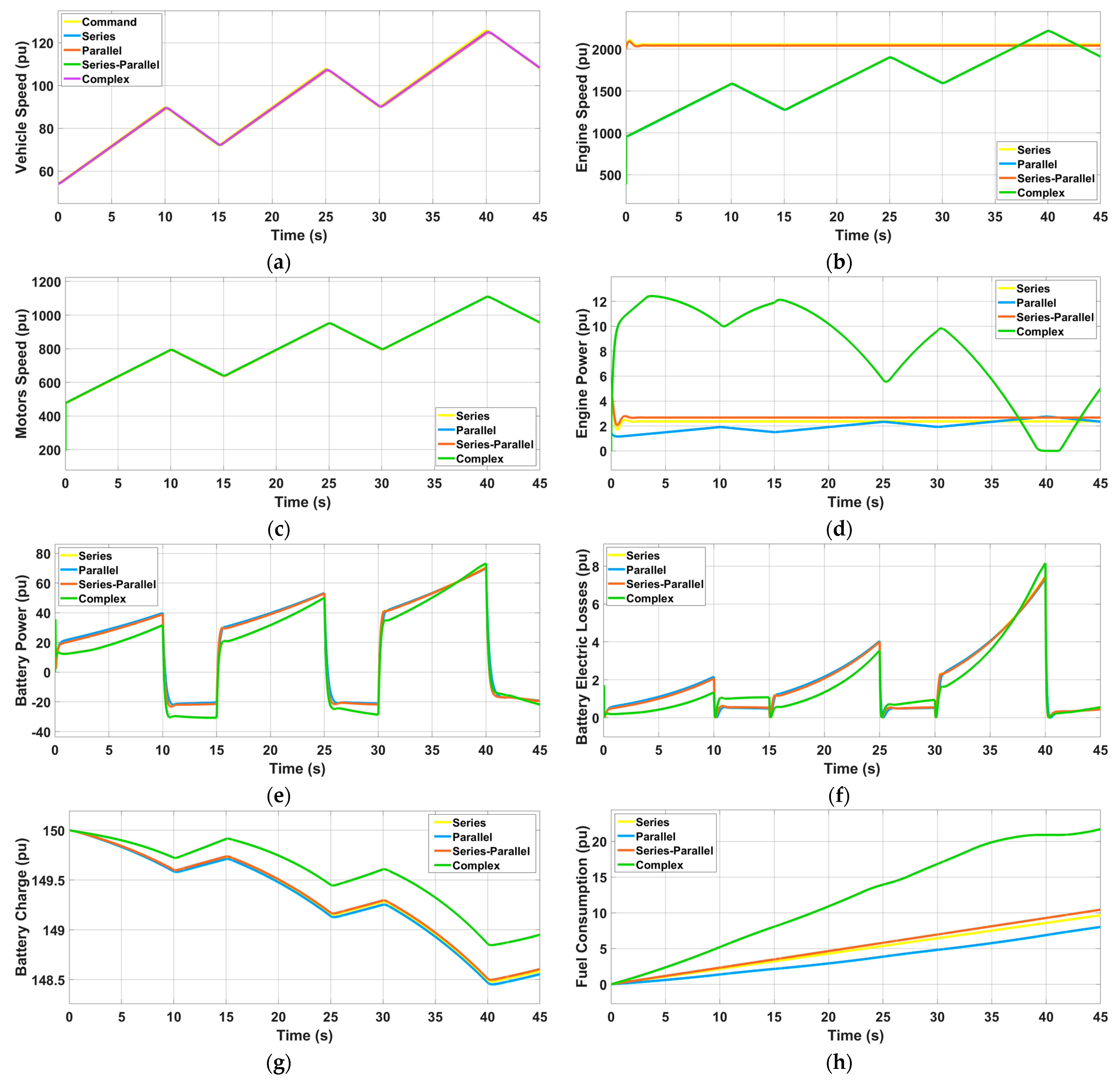
4.3. HEV Performance Parameters for Test Input-3

Extreme acceleration cases such as speed racing can be mimicked using the stand-step acceleration signal. The acceleration is applied linearly for 10 s followed by a brief deceleration of 5 s applied for 45 s. The speed response of various HEV architectures used in this study for step acceleration is given in Figure 8a. In comparison, the speed response of almost all HEVs is 125 units. Among these, the parallel HEV architecture touched 124.7 units. When HEVs are excited by test input-3, the engine speed profiles are given in Figure 8b. From this these responses, the series architecture was superior and the series-parallel was the next to have higher engine speeds.
The motor speed profiles of HEV architectures for test input-3 are given in Figure 8c. From these responses, the parallel architecture was demonstrated to be superior. The engine power profiles of HEV architectures for test input-3 are given in Figure 8d. Based on these responses, the parallel architecture was the superior one and the series was the next to have the best and least engine power values. The profiles of battery power for various HEVs, when excited by test input-3, are given in Figure 8e. From these plots, it is observed that the complex architecture used less battery power while the parallel architecture utilized very high battery power. Battery electric loss profiles for test input-3 for all the HEV architectures are given in Figure 8f. From this, it was observed that complex architecture had the least loss. The battery charge state for HEV architectures for step acceleration is given in Figure 8g. From these profiles, it is noted that the complex architecture has been maintained well when compared to the other HEV architectures. The fuel consumption profiles of all the HEV architectures discussed in this study are plotted in Figure 8h.
On analyzing these plots, the complex HEV architecture has consumed the most fuel and the parallel architecture expends less fuel. The fuel consumption of the series and series-parallel architecture is the same with less than a unit difference.

4.4. Validation of 4WD HEV Architectures

The criteria followed for validating the performance of 4WD HEV architectures are given in Figure 9. As shown, the effectiveness of the 4WD HEV type is validated by comparing it with the FWD HEV type [34] and the RWD HEV type [35]. In all these cases, four key architectures, namely, (1) series architecture, (2) parallel architecture, (3) series-parallel architecture, and (4) complex architecture are simulated. Their performance metrics (namely, vehicle speed, engine speed, motor speed, engine power, battery power, battery electrical losses, battery charge, and fuel consumption) are computed under three test conditions (namely, continuous acceleration, pulse-type acceleration, and step-up type acceleration). All these performance parameters of the 4WD HEV architectures are computed based on their characteristics depicted in Figure 6, Figure 7 and Figure 8.
All the measurements from the above-mentioned validation criteria are tabulated and compared as given in Table 3 to find the best architecture. The desired value for each performance metric is considered to identify the superior architecture in each case. From this table, it is observed that the 4WD HEV architectures have shown superior performance in most of the cases when compared to FWD type and RWD type HEVs. Further, among various 4WD HEV architectures, the 4WD parallel HEV architecture has shown superior performance compared to the 4WD series, 4WD series-parallel, and 4WD complex architectures.

5. Conclusions

An in-depth investigation of the critical performance metrics of four important HEV architectures when excited with three types of dynamic operating conditions is conducted and presented. A comparative analysis of these performance metrics was elucidated in the presence of dynamic inputs. A comparison of the performance metric of 4WD with FWD and RWD is also presented. This comparison reveals that the 4WD HEV architectures have shown superior performance in most of the cases when compared to FWD type and RWD type HEVs. Further, among various 4WD HEV architectures, the 4WD Parallel HEV architecture has shown superior performance compared to the 4WD series, 4WD series-parallel, and 4WD complex architectures.
From the comparative quantities presented in Table 3, it is observed that the parallel 4WD HEV architecture showed superior performance for parameters, namely, (1) motor speed, (2) engine power, (3) battery power, and (4) fuel consumption, whereas, for the battery charge parameter, the complex 4WD HEV architecture showed good performance. For the engine speed parameter, the series 4WD HEV architecture showed good performance. Hence, from all these observations, the following recommendations can be derived.
  • If fuel economy is to be prioritized, the parallel architecture is recommended;
  • If power and speed are to be prioritized over fuel economy, the complex architecture is recommended;
  • If the balanced fuel, power, and speed are to be prioritized, the parallel architecture is recommended. This can be reinforced by the conclusions presented in [37].
The conclusions are made based on the assumption that the parameter under consideration and all other system parameters do not undergo any drastic change and are within the allowable limits of operation. This is the limitation of the present work. The same type of analysis can be done under a proper energy management scheme and the results can be verified accordingly.

Author Contributions

Conceptualization, D.J.P.; data curation, C.P.R.; formal analysis, Y.V.P.K.; funding acquisition, H.M.K.; investigation, B.R.S.; methodology, Y.V.P.K.; project administration, M.A. and H.M.K.; resources, M.A.; software, D.J.P.; supervision, Y.V.P.K.; validation, C.P.R.; visualization, H.M.K.; writing—original draft, B.R.S.; writing—review and editing, D.J.P. and M.A. All authors have read and agreed to the published version of the manuscript.

Funding

This research received no external funding.

Institutional Review Board Statement

Not applicable.

Informed Consent Statement

Not applicable.

Data Availability Statement

Not applicable.

Acknowledgments

The authors would like to acknowledge the VIT-AP University, Amaravati, Andhra Pradesh, India; Jamia Millia Islamia Central University, New Delhi, India; University of Dubai, Dubai, United Arab Emirates; University of Johannesburg, Auckland Park, South Africa; and University of Santiago, Chile for supporting this collaborative research.

Conflicts of Interest

The authors declare no conflict of interest.

References

  1. Amir, M.; Zaheeruddin; Haque, A.; Kurukuru, V.S.B.; Baksh, F.I.; Ahmad, A. Agent Based Online Learning Approach for Power Flow Control of Electric Vehicle Fast Charging Station Integrated with Smart Microgrid. IET Renew. Power Gener. 2020, 14, 1–13. [Google Scholar] [CrossRef]
  2. Amir, M.; Zaheeruddin; Haque, A. Optimal Scheduling of Charging/Discharging Power and EVs Pattern Using Stochastic Techniques in V2G System. In Proceedings of the IEEE Transportation Electrification Conference (ITEC), New Delhi, India, 16–19 December 2021. [Google Scholar] [CrossRef]
  3. Prasanth, B.; Paul, R.; Kaliyaperumal, D.; Kannan, R.; Venkata Pavan Kumar, Y.; Kalyan Chakravarthi, M.; Venkatesan, N. Maximizing Regenerative Braking Energy Harnessing in Electric Vehicles Using Machine Learning Techniques. Electronics 2023, 12, 1119. [Google Scholar] [CrossRef]
  4. Potnuru, D.; Ayyarao, T.S.L.V.; Kumar, L.V.S.; Kumar, Y.V.P.; Pradeep, D.J.; Reddy, C.P. Salp Swarm Algorithm Based Optimal Speed Control For Electric Vehicles. Int. J. Power Electron. Drive Syst. 2022, 13, 755–763. [Google Scholar] [CrossRef]
  5. Rao, S.N.V.B.; Kumar, Y.V.P.; Pradeep, D.J.; Reddy, C.P.; Flah, A.; Kraiem, H.; Al-Asad, J.F. Power Quality Improvement in Renewable-Energy-Based Microgrid Clusters Using Fuzzy Space Vector PWM Controlled Inverter. Sustainability 2022, 14, 4663. [Google Scholar] [CrossRef]
  6. Reddy, Y.J.; Kumar, Y.V.P.; Raju, K.P.; Ramsesh, A. Retrofitted Hybrid Power System Design With Renewable Energy Sources for Buildings. IEEE Trans. Smart Grid 2012, 3, 2174–2187. [Google Scholar] [CrossRef]
  7. Khalid, H.M.; Flitti, F.; Muyeen, S.M.; El Moursi, M.S.; Sweidan, T.O.; Yu, X. Parameter Estimation of Vehicle Batteries in V2G Systems: An Exogenous Function-Based Approach. IEEE Trans. Ind. Electron. 2022, 69, 9535–9546. [Google Scholar] [CrossRef]
  8. Khalid, H.M.; Peng, J.C.-H. H. Bi-Directional Charging in V2G Systems: An In-Cell Variation Analysis of Vehicle Batteries. IEEE Syst. J. 2020, 14, 3665–3675. [Google Scholar] [CrossRef]
  9. Qiu, L.; Qian, L.; Zomorodi, H.; Pisu, P. Global Optimal Energy Management Control Strategies for Connected Four-wheel-drive Hybrid Electric Vehicles. IET Intell. Transp. Syst. 2017, 11, 264–272. [Google Scholar] [CrossRef]
  10. Yim, S.; Choi, J.; Yi, K. Coordinated Control of Hybrid 4WD Vehicles for Enhanced Maneuverability and Lateral Stability. IEEE Trans. Veh. Technol. 2012, 61, 1946–1950. [Google Scholar] [CrossRef]
  11. Iervolino, R.; Sakhnevych, A. Modeling, Simulation and Control of a 4WD Electric Vehicle with In-Wheel Motors. In Advances in Service and Industrial Robotics; Ferraresi, C., Quaglia, G., Eds.; Mechanisms and Machine Science; Springer International Publishing: Cham, Switzerland, 2018; Volume 49, pp. 444–455. ISBN 978-3-319-61275-1. [Google Scholar] [CrossRef]
  12. Hall, J.; Bassett, M.; Borman, S.; Lucas, T.; Whitehead, A. Through-the-Road Parallel Hybrid with In-Wheel Motors; SAE Technical Paper 2016-01-1160; SAE International: Warrendale, PA, USA, 2016. [Google Scholar] [CrossRef]
  13. Raslavičius, L.; Keršys, A.; Makaras, R. Management of Hybrid Powertrain Dynamics and Energy Consumption for 2WD, 4WD, and HMMWV Vehicles. Renew. Sustain. Energy Rev. 2017, 68, 380–396. [Google Scholar] [CrossRef]
  14. Qiu, L.; Qian, L.; Zomorodi, H.; Pisu, P. Design and Optimization of Equivalent Consumption Minimization Strategy for 4WD Hybrid Electric Vehicles Incorporating Vehicle Connectivity. Sci. China Technol. Sci. 2018, 61, 147–157. [Google Scholar] [CrossRef]
  15. Han, K.; Choi, M.; Lee, B.; Choi, S.B. Development of a Traction Control System Using a Special Type of Sliding Mode Controller for Hybrid 4WD Vehicles. IEEE Trans. Veh. Technol. 2018, 67, 264–274. [Google Scholar] [CrossRef]
  16. Shen, Y.; Zhang, B.; Liu, H.; Cui, Y.; Hussain, F.; He, S.; Hu, F. Design and Development of a Novel Independent Wheel Torque Control of 4WD Electric Vehicle. Mechanics 2019, 25, 210–218. [Google Scholar] [CrossRef]
  17. Ju, F.; Zhuang, W.; Wang, L.; Zhang, Z. Optimal Sizing and Adaptive Energy Management of a Novel Four-Wheel-Drive Hybrid Powertrain. Energy 2019, 187, 116008. [Google Scholar] [CrossRef]
  18. Zhao, Z.; Lei, D.; Chen, J.; Li, H. Optimal Control of Mode Transition for Four-Wheel-Drive Hybrid Electric Vehicle with Dry Dual-Clutch Transmission. Mech. Syst. Signal Process. 2018, 105, 68–89. [Google Scholar] [CrossRef]
  19. Kaban, S.; Dong, Z.; Crawford, C. Performance Modeling and Benchmark Analysis of an Advanced 4WD Series-Parallel PHEV Using Dynamic Programming. In Proceedings of the 2015 IEEE Vehicle Power and Propulsion Conference (VPPC), Montreal, QC, Canada, 19–22 October 2015; pp. 1–6. [Google Scholar] [CrossRef]
  20. Wu, D.; Li, Y.; Du, C.; Ding, H.; Li, Y.; Yang, X.; Lu, X. Fast Velocity Trajectory Planning and Control Algorithm of Intelligent 4WD Electric Vehicle for Energy Saving Using Time-based MPC. IET Intell. Transp. Syst. 2019, 13, 153–159. [Google Scholar] [CrossRef]
  21. Wang, W.; Qu, F.; Wang, Q.; Wu, C. Research on Energy Control Strategy of 4WD Hybrid Electric Vehicle Based on Fuzzy Control. In Proceedings of the 2018 2nd IEEE Advanced Information Management, Communicates, Electronic and Automation Control Conference (IMCEC), Xi’an, China, 25–27 May 2018; pp. 1806–1811. [Google Scholar] [CrossRef]
  22. Xu, L.; Li, Z.; Sun, H.; Fan, J.; Bai, Q.; Ou, Y.; Wang, P.; Deng, B. Study on Control Strategy for Series-Parallel Hybrid Electric Vehicles. J. Phys. Conf. Ser. 2020, 1617, 012059. [Google Scholar] [CrossRef]
  23. Baumann, P.; Schroeder, M.; Kurz, H.; Maier, T.; Thiel, W.; Strehl, U. Investigation of the Influencing Parameters Using Optimized Exhaust Emissions Measurement Systems with Different Modern Plug-In Hybrid Electrical Vehicles; SAE Technical Paper 2015-01-1069; SAE International: Warrendale, PA, USA, 2015. [Google Scholar] [CrossRef]
  24. Xie, Y.; Wang, S. Research on Regenerative Braking Control Strategy and Simulink Simulation for 4WD Electric Vehicle. IOP Conf. Ser. Mater. Sci. Eng. 2018, 398, 012013. [Google Scholar] [CrossRef]
  25. Park, G.; Choi, S.B. Development of a Torque Vectoring System in Hybrid 4WD Vehicles to Improve Vehicle Safety and Agility. In Proceedings of the 2019 American Control Conference (ACC), Philadelphia, PA, USA, 10–12 July 2019; pp. 316–321. [Google Scholar] [CrossRef]
  26. Basrah, M.S.; Velenis, E.; Cao, D. Four Wheel Torque Blending for Slip Control in a Hybrid Electric Vehicle with a Single Electric Machine. In Proceedings of the 2015 International Conference on Sustainable Energy Engineering and Application (ICSEEA), Bandung, Indonesia, 5–7 October 2015; pp. 19–24. [Google Scholar] [CrossRef]
  27. Farrokhzad Ershad, N.; Tafazzoli Mehrjardi, R.; Ehsani, M. High-Performance 4WD Electric Powertrain With Flywheel Kinetic Energy Recovery. IEEE Trans. Power Electron. 2021, 36, 772–784. [Google Scholar] [CrossRef]
  28. Vantsevich, V.V.; Paldan, J.R.; Farley, B.K. Mobility Optimization and Control of a 4x4 HE-Vehicle in Curvilinear Motion on Stochastic Terrain. In Proceedings of the 18th International Conference on Advanced Vehicle Technologies, Charlotte, NC, USA, 21 August 2016; p. V003T01A005. [Google Scholar] [CrossRef]
  29. Andari, W.; Ben Yahia, M.S.; Allagui, H.; Mami, A. Modeling and Simulation of PEM Fuel Cell/Supercapacitor Hybrid Power Sources for an Electric Vehicle. In Proceedings of the 2019 10th International Renewable Energy Congress (IREC), Sousse, Tunisia, 26–28 March 2019; pp. 1–6. [Google Scholar] [CrossRef]
  30. He, R.; Song, Z.; Li, J.; Ouyang, M. Optimal Torque Distribution Strategy Considering Energy Loss and Tire Adhesion for 4WD Electric Vehicles. In Proceedings of the 2017 IEEE Transportation Electrification Conference and Expo, Asia-Pacific (ITEC Asia-Pacific), Harbin, China, 7–10 August 2017; pp. 1–6. [Google Scholar] [CrossRef]
  31. Zeng, X.; Zhang, X.; Gao, F.; Yang, T.; Nie, Y.; Chen, J. Analysis of the Efficiency of Two Different Electric-Continuously Variable Transmission for Hybrid Electric Bus. In Proceedings of the 2019 3rd Conference on Vehicle Control and Intelligence (CVCI), Hefei, China, 21–22 September 2019; pp. 1–4. [Google Scholar] [CrossRef]
  32. Vitázek, I.; Tkáč, Z.; Mojžiš, M. Evaluation of Drive Type Properties on the Basis of Engine-Speed Maps. In Proceedings of the AIP Conference Proceedings, Sturovo, Slovakia, 7 August 2018; p. 020021. [Google Scholar] [CrossRef]
  33. Nguyen, C.T.P.; Trovao, J.P.F.; Nguyen, B.-H.; Ta, M.C. Powertrain Analysis of an All-Wheel-Drive Off-Road Electric Vehicle. In Proceedings of the 2019 IEEE Vehicle Power and Propulsion Conference (VPPC), Hanoi, Vietnam, 14–17 October 2019; pp. 1–6. [Google Scholar] [CrossRef]
  34. Siddharth, B.R.; Pradeep, D.J.; Kumar, Y.V.P.; Reddy, C.P.; Flah, A. Dynamic Performance Analysis of Front-Wheel Drive Hybrid Electric Vehicle Architectures under Different Real-Time Operating Conditions. Int. J. Powertrains 2022, 11, 62. [Google Scholar] [CrossRef]
  35. Raja Siddharth, B.; Sai Chandu, V.; Mani Babu, D.; John Pradeep, D.; Pavan Kumar, Y.V. Performance Analysis of Hybrid Electric Vehicle Architectures under Dynamic Operating Conditions. Int. J. Adv. Sci. Technol. 2020, 29, 4370–4390. [Google Scholar]
  36. Mehrdad, E.; Yimin, G.; Emadi, A. Modern Electric, Hybrid Electric, and Fuel Cell Vehicles: Fundamentals, Theory, and Design; CRC Press: Boca Raton, FL, USA, 2010. [Google Scholar] [CrossRef]
  37. Chen, B.; Li, X.; Evangelou, S. Comparative Study of Hybrid Powertrain Architectures from a Fuel Economy Perspective. In Proceedings of the 14th International Symposium on Advanced Vehicle Control (AVEC), Beijing, China, 16–20 July 2018; Available online: https://discovery.ucl.ac.uk/id/eprint/10083602 (accessed on 23 May 2023).
Figure 1. Schematics of the four key architectures of 4WD HEVs. (a) Series 4WD HEV architecture; (b) parallel 4WD HEV architecture; (c) series-parallel 4WD HEV architecture; (d) complex 4WD HEV architecture.
Wevj 14 00138 g001aWevj 14 00138 g001b
Figure 2. Simulink model of the series HEV architecture.
Wevj 14 00138 g002
Figure 3. Simulink model of the parallel HEV architecture.
Wevj 14 00138 g003
Figure 4. Simulink model of the series-parallel HEV architecture.
Wevj 14 00138 g004
Figure 5. Simulink model of the complex HEV architecture.
Wevj 14 00138 g005
Figure 6. Response of critical parameters for different HEV architectures subjected to test input-1. (a) Vehicle speed responses for test input-1; (b) engine speed responses for test input-1; (c) motor speed responses for test input-1; (d) engine power responses for test input-1; (e) battery power responses for test input-1; (f) battery electric loss responses for test input-1; (g) battery charge responses for test input-1; (h) fuel consumption responses for test input-1.
Wevj 14 00138 g006
Figure 7. Response of critical parameters for different HEV architectures subjected to test input-2. (a) Vehicle speed responses for test input-2; (b) engine speed responses for test input-2; (c) motor speed responses for test input-2; (d) engine power responses for test input-2; (e) battery power responses for test input-2; (f) battery electric loss responses for test input-2; (g) battery charge responses for test input-2; (h) fuel consumption responses for test input-2.
Wevj 14 00138 g007aWevj 14 00138 g007b
Figure 8. Response of critical parameters for different HEV architectures subjected to test input-3. (a) Vehicle speed responses for test input-3; (b) engine speed responses for test input-3; (c) motor speed responses for test input-3; (d) engine power responses for test input-3; (e) battery power responses for test input-3; (f) battery electric loss responses for test input-3; (g) battery charge responses for test input-3; (h) fuel consumption responses for test input-3.
Wevj 14 00138 g008
Figure 9. Validation criteria.
Wevj 14 00138 g009
Table 1. Various test conditions and observed parameters of this study.
Test Conditions or InputsObserved Parameters
1. Continuous acceleration1. Vehicle speed
2. Pulse-type acceleration 2. Engine speed
3. Step-up type acceleration3. Motor speed
4. Engine power
5. Battery power
6. Battery electrical loss
7. Battery charge
8. Fuel consumption
Table 2. Parameters used in this study.
ParameterDescription
TwheelWheel torque
SwheelWheel speed
igrTransmission gear ratio
iogDrive final gear ratio
ηtwDriveline efficiency
PengEngine load power
SengEngine speed
FwAerodynamic drag
FfFrictional force (rolling friction)
MvehicleMass of the vehicle
SvVehicle speed
γfFuel’s mass density (kg/L)
FgGrading force
PmaxMaximum power delivered by battery to load
VoperBattery operating voltage
RinternalInternal resistance
RconConductor resistance
frTire rolling resistance coefficient (=0.01)
gGravity acceleration in 9.80 m/s2
ρaAir density (=1.18 kg/m3),
AfVehicle’s front area (=3 m2)
CDAerodynamic drag coefficient (=0.4)
ηtTransmission efficiency
ηmTraction motor efficiency
ηt,eWheels transmission efficiency
Table 3. Critical performance comparison of 4WD, FWD, and RWD HEV architectures.
Performance MetricsTest
Input
4WD HEV ArchitecturesFWD HEV Architectures [34]RWD HEV Architectures [35]Superior Architecture
SeriesParallelSeries-ParallelComplexSeriesParallelSeries-ParallelComplexSeriesParallelSeries-ParallelComplex
Vehicle Speed
(Desired: High value)
1195.1196.2195.8194.5140144.2141.7142.2139.9147.2141.7155.74WD
Parallel
271.9571.9271.9672.0771.7671.6571.8472.0671.871.9371.818.084WD Complex
3125.1124.7125.1125.1116.6118117.2119.7116.5118.911771.74WD
Motor Speed
(Desired: High value)
1802.2803.2802.5790.112471284126112651246131112611343RWD Complex
2540.7540.9540.8536.1633.7636.6634.3637.3636.3637.1636.4645.3RWD Complex
3796.4796.7796.5790.410351049103910601035105110401065RWD Complex
Engine Speed
(Desired: High value)
1205416062043158020572567204325292162559621536002RWD Complex
22057108220431072205612722043127520022020205318034WD
Series
3205515932042158120572097204321202162451221543944RWD Parallel
Engine Power
(Desired: Low value)
13.012.033.224.662.82.23.43.54.95.54.945.04WD
Parallel
22.671.302.939.893.21.353.4610.044.93.44.946.984WD
Parallel
32.591.962.867.112.372.452.676.514.95.174.9424.74WD
Parallel
Battery Power
(Desired: High value)
144.344.444.344.051.4155.3652.9254.0450.855.152.342.0FWD Parallel
238.948.630.724.325.6528.0325.9918.1325.0927.425.48.454WD
Parallel
377.690.475.536.627.8629.829.0234.0142.0145.242.834.74WD
Parallel
Batter Electric Loss
(Desired: Low value)
18.037.958.078.353.744.403.394.103.654.493.80.79RWD Complex
22.522.612.502.800.841.030.880.900.640.740.660.10RWD Complex
38.338.378.287.841.011.151.061.342.422.842.51.19FWD
Series
Battery Charge
(Desired: High value)
1149.1149.1149.1149.2147.6147.3147.5147.5148.7148.7148.1148.64WD Complex
2149.9149.9149.9150.3149.8149.7149.8150.1149.9149.9149.9150.14WD Complex
3149.4149.3149.4149.6147.8148.6147.8149149.1149.4149.3149.04WD Complex
Fuel Consumption
(Desired: Low value)
19.611.610.410.19.679.3910.4411.1419.119.810.429.64WD
Series
29.65.310.421.39.695.3910.4421.49.010.910.411.34WD
Parallel
39.68.010.421.79.678.8610.4422.699.116.0610.442.364WD
Parallel
Disclaimer/Publisher’s Note: The statements, opinions and data contained in all publications are solely those of the individual author(s) and contributor(s) and not of MDPI and/or the editor(s). MDPI and/or the editor(s) disclaim responsibility for any injury to people or property resulting from any ideas, methods, instructions or products referred to in the content.

