Article

Direct Torque Control of an Induction Motor Using Fractional-Order Sliding Mode Control Technique for Quick Response and Reduced Torque Ripple

1
Department of Electrical & Electronics Engineering, Gayatri Vidya Parishad College of Engineering (Autonomous), Madhurawada, Visakhapatnam 530048, India
2
Department of Electrical & Electronics Engineering, Seshadri Rao Gudlavalleru Engineering College, Gudlavalleru, Vijayawada 521356, India
*
Author to whom correspondence should be addressed.
World Electr. Veh. J. 2023, 14(6), 137; https://doi.org/10.3390/wevj14060137
Submission received: 30 April 2023 / Revised: 18 May 2023 / Accepted: 24 May 2023 / Published: 25 May 2023

Abstract

:
The performance of electric drive propulsion systems is often degraded by the high torque and flux ripples of an electric drive. Traditional control methods, such as proportional plus integral (PI) controllers and classical sliding mode controllers (SMCs), have shown good response and reduced torque ripple, but even lower ripple content at low voltage levels is required for its effective use in electric vehicle (EV) applications. In this paper, a new direct torque control (DTC) technique with space vector pulse width modulation (SVPWM) using fractional-order sliding mode control (FOSMC) for a two-level inverter (2LI) at constant switching frequency is proposed. The effectiveness of this proposed controller is compared with a conventional proportional-integral controller and a conventional sliding mode controller (SMC). Simulink models are developed using MATLAB version R2018a to analyze the robustness of the proposed control strategy. Simulation results demonstrate the advantage of the proposed controller in reducing the torque ripples at steady state with less settling time during sudden load change conditions. The proposed control technique also demonstrates better utilization of the stator flux through flux trajectory waveforms.

1. Introduction

In recent years, there has been a significant shift towards the use of electric vehicles (EVs) as a means of transportation because of the increasing concern about environmental pollution and the depletion of fossil fuels. Alternating current and direct current motors are finding widespread applications in EVs, with induction motors (IMs), permanent magnet synchronous motors (PMSMs), switched reluctance motors (SRMs), and brushless DC (BLDC) motors being the most commonly used [1]. Among these, induction motors draw much attention for use in EV applications, owing to their low cost, low maintenance requirements, robustness, and ruggedness. To control the torque in an induction motor drive, there are several control techniques available, including direct torque control (DTC), field-oriented control (FOC), vector control, and scalar control. Among all of these, DTC and FOC are the industrial standards for controlling the torque in an induction motor. However, DTC is gaining more attention in recent times because of its simplicity and good dynamics [2,3].
In the last few decades of work, many researchers have proposed various control strategies for the efficient operation of induction motors. Benchaib and Edwards et al. [4] developed an SMC for an induction motor for the asymptotic tracking of speed and flux. The control law is implemented using a sliding mode observer. Kuo Kai et al. [5] proposed flux-compensated direct torque control to enhance the induced torque levels at low-speed operating points. Zhuang et al. [6] proposed a fuzzy sliding mode speed controller for the high-level performance of an induction motor drive. Peng et al. [7] developed a neural network sliding mode control law for robustness and presented a radial basis neural network to reduce the chattering. Hiba et al. [8] proposed a proportional-integral controller and space vector modulation–based direct torque control techniques for three-phase induction motors. Sung et al. [9] fabricated a fuzzy DTC–based chip to reduce torque and flux variations. Xing Zhang et al. [10] developed a new topology-based higher-order filter connecting an extra capacitor parallel to a resonant circuit to mitigate harmonic currents. Zhao et al. [11] used an adaptive SMC in place of a PID controller to increase anti-interference capability. The bandwidth of the torque hysteresis controller is adjusted using fuzzy control. Yang et al. [12] compared performance analysis of permanent magnet synchronous motors, induction motors, and reluctance motors for electric vehicle applications. Ammar et al. [13] used high-order sliding mode controllers to improve the SVM-DTC performance. Niu et al. [14] presented a simple duty cycle–modulated DTC of a permanent magnet synchronous motor drive. Oukaci et al. [15] proposed a synthesis of sliding mode control and nonlinear control techniques for speed and rotor flux control to overcome the parametric uncertainties. Wang et al. [16] proposed a direct torque control technique based on space vector modulation for torque and flux ripples. Alsofyani et al. [17] addressed the problem of poor flux regulation at low speeds using two dynamic hysteresis torque bands. It also presents the analysis of flux degradation in the work. Kumar and Ali [18] developed a fractional-order sliding mode control technique to suppress chattering from power and current signals of grid converter DC/AC converter. Babes et al. [19] proposed a fractional-order terminal sliding mode control technique for the output voltage regulation of a DC-DC Buck converter.
Saheb and Gudey [20] designed a fractional-order sliding mode controller for a DC-AC inverter to improve the dynamic response of AC output voltage. Lascu et al. [21] developed the theoretical aspects of stability and gain selection criteria for novel super-twisting sliding mode direct torque and flux control of induction motors. Munoz-Hernandez et al. [22] designed a fractional-order PI controller for an electric-vehicle traction system. Masoumkhani and Taheri [23] proposed a duty cycle–control method to reduce harmonic loss in the direct torque control of a six-phase induction motor. Sami et al. [24] proposed an integral super-twisting SMC in the outer loop for torque and speed control. An observer for speed estimation was also designed and presented. Mohan and Satish [25] proposed a constant switching frequency–based direct torque control technique for electric vehicle motor applications. Xu et al. [26] proposed a sliding mode direct thrust control strategy for the speed control of a liner induction machine. Delavari and Veisi [27] proposed a fractional-order sliding mode controller for the speed control of wind generators. Benbouhenni and Bizon [28] proposed a super-twisting algorithm–based third-order sliding mode control technique for the flux and torque control of induction motors used in wind turbines. Yu et al. [29] proposed a control strategy combining nonlinear fractional-order sliding mode controller and linear-model predictive control for the altitude tracking of spacecraft. Shiravani et al. [30] applied an integral sliding mode control strategy for induction motor vector control to compensate for the parametric variations and load disturbances. Kotb et al. [31] proposed a methodology for tuning cascaded PID controller parameters based on a unimodal sampling algorithm and spotted hyena optimizer to control the speed of a switched reluctance motor and reduce the torque ripples. Yang et al. [32] designed a speed sensorless control strategy considering the combination of a radial basis function neural network and fractional sliding mode control techniques. De Klerk and Saha [33] analyzed the performance of traction motors in battery electric vehicles considering a direct torque control strategy. Wang et al. [34] proposed a discrete sliding mode observer to enhance the operating range of a sliding mode–based model reference adaptive system. Adigintla and Aware [35] designed a robust fractional-order controller for induction motor speed control under parameter variations.
All the above-mentioned control schemes have improved the induction motor drive performance by reducing flux and torque ripples and eliminating the main drawback of the variable switching-frequency nature of the conventional DTC scheme. However, there is still a need to reduce the flux and torque ripples of an induction motor drive, particularly for EV applications at low speeds. Hence, in this work, a fractional-order sliding control (FOSMC) technique for reducing the torque and flux ripples operating at a fixed switching frequency is proposed. The main contributions of this work include
  • Control algorithm of an FOSMC for SVM-based DTC for induction motor drives (IMDs);
  • Derivation of the electromagnetic torque of an IMD using an FOSMC-DTC scheme;
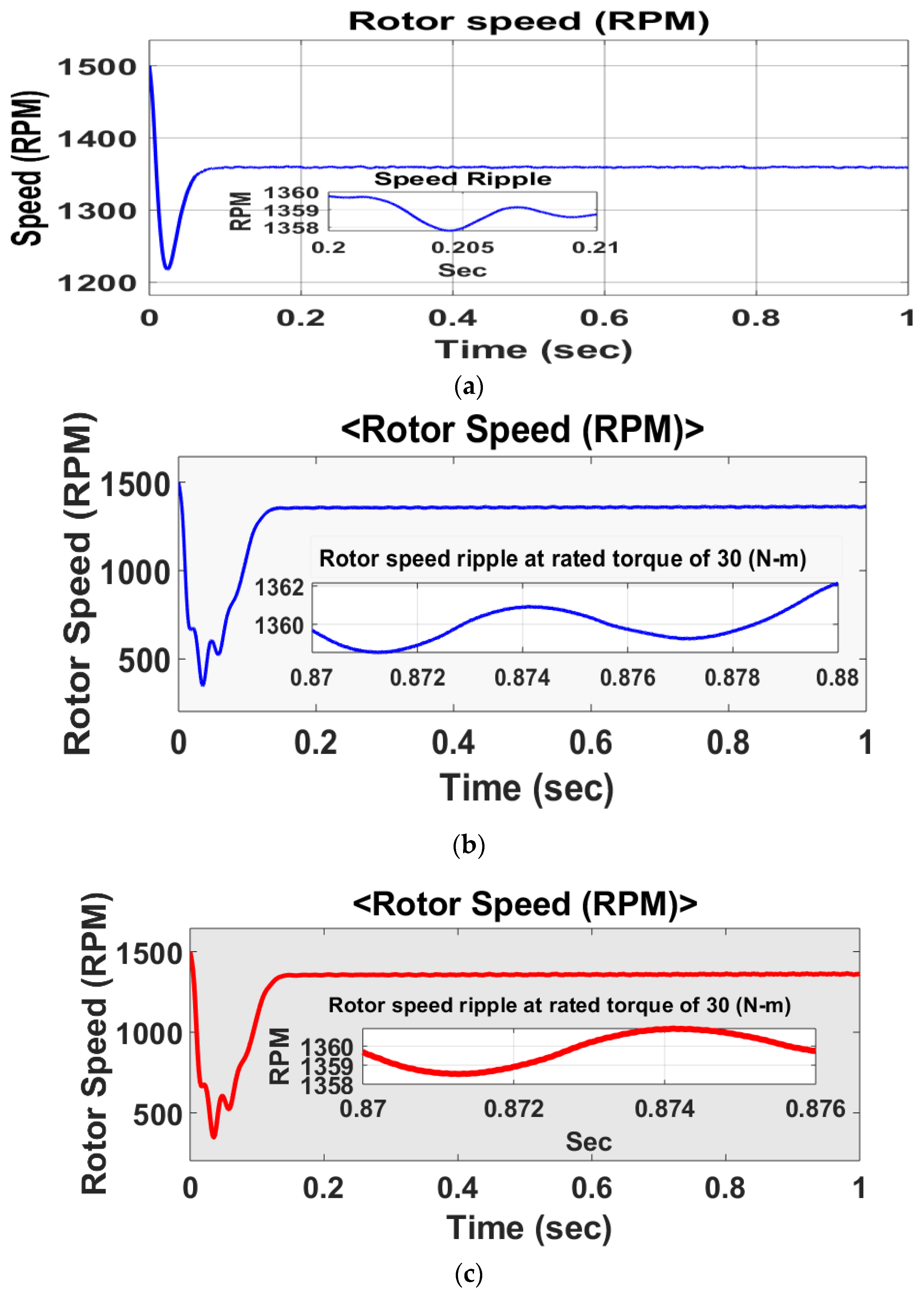
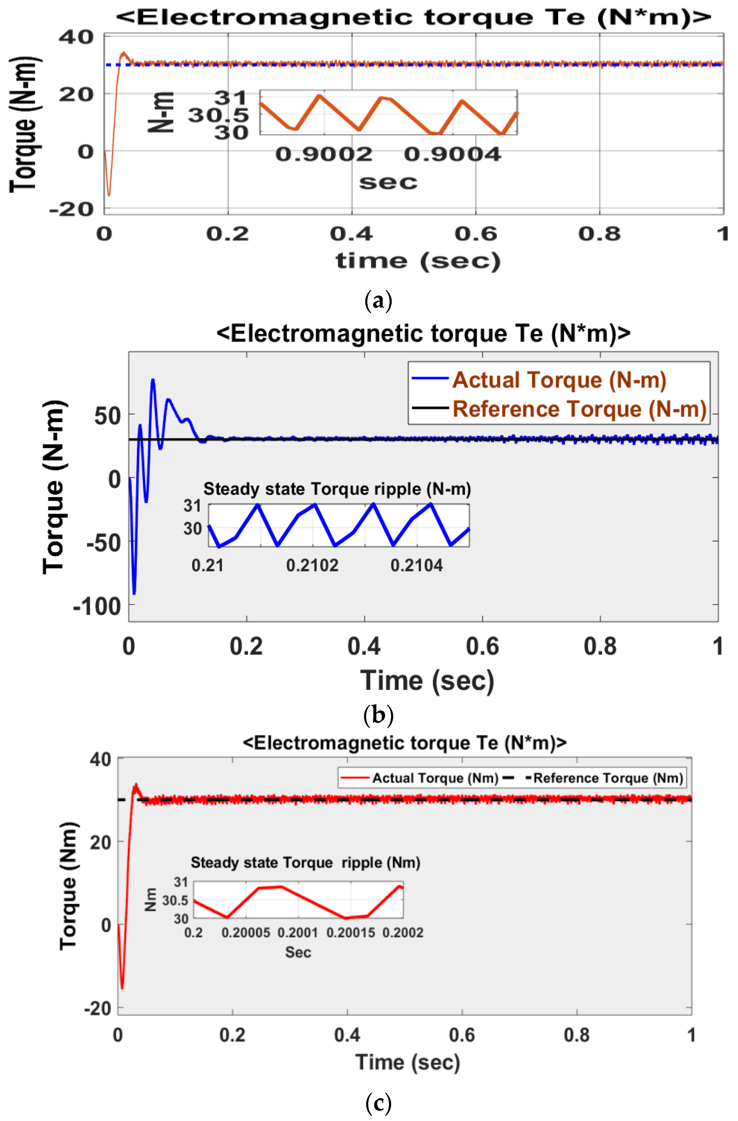
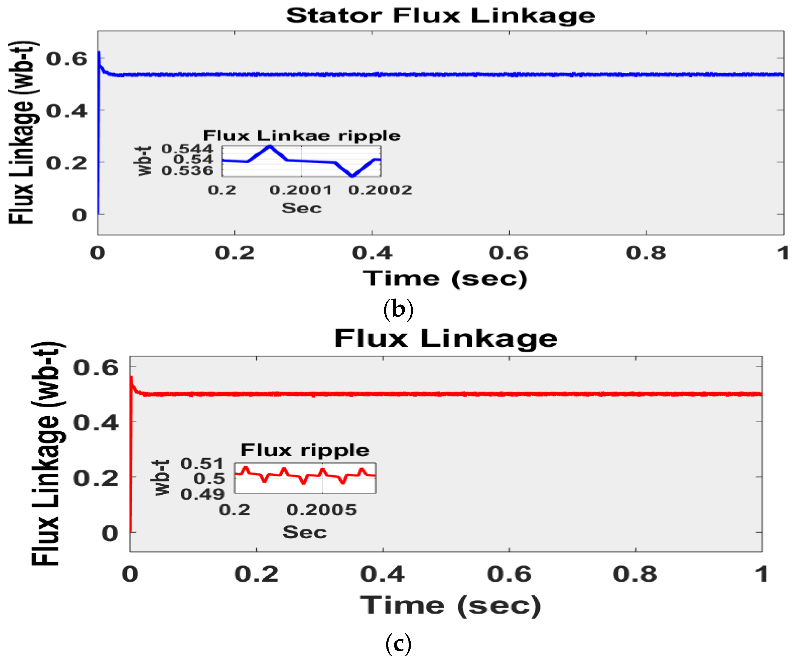
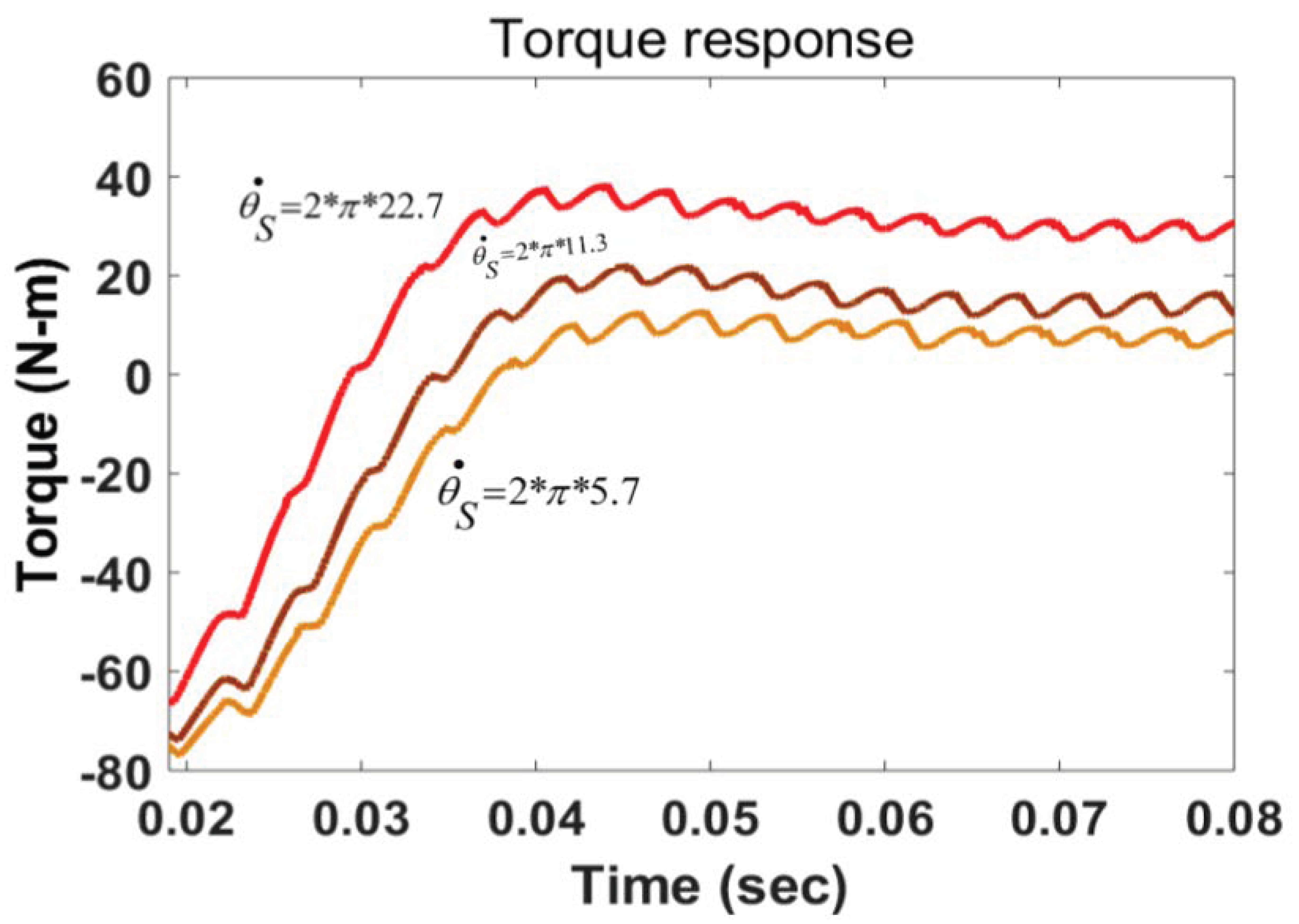
  • Minimization of torque ripples during steady state;
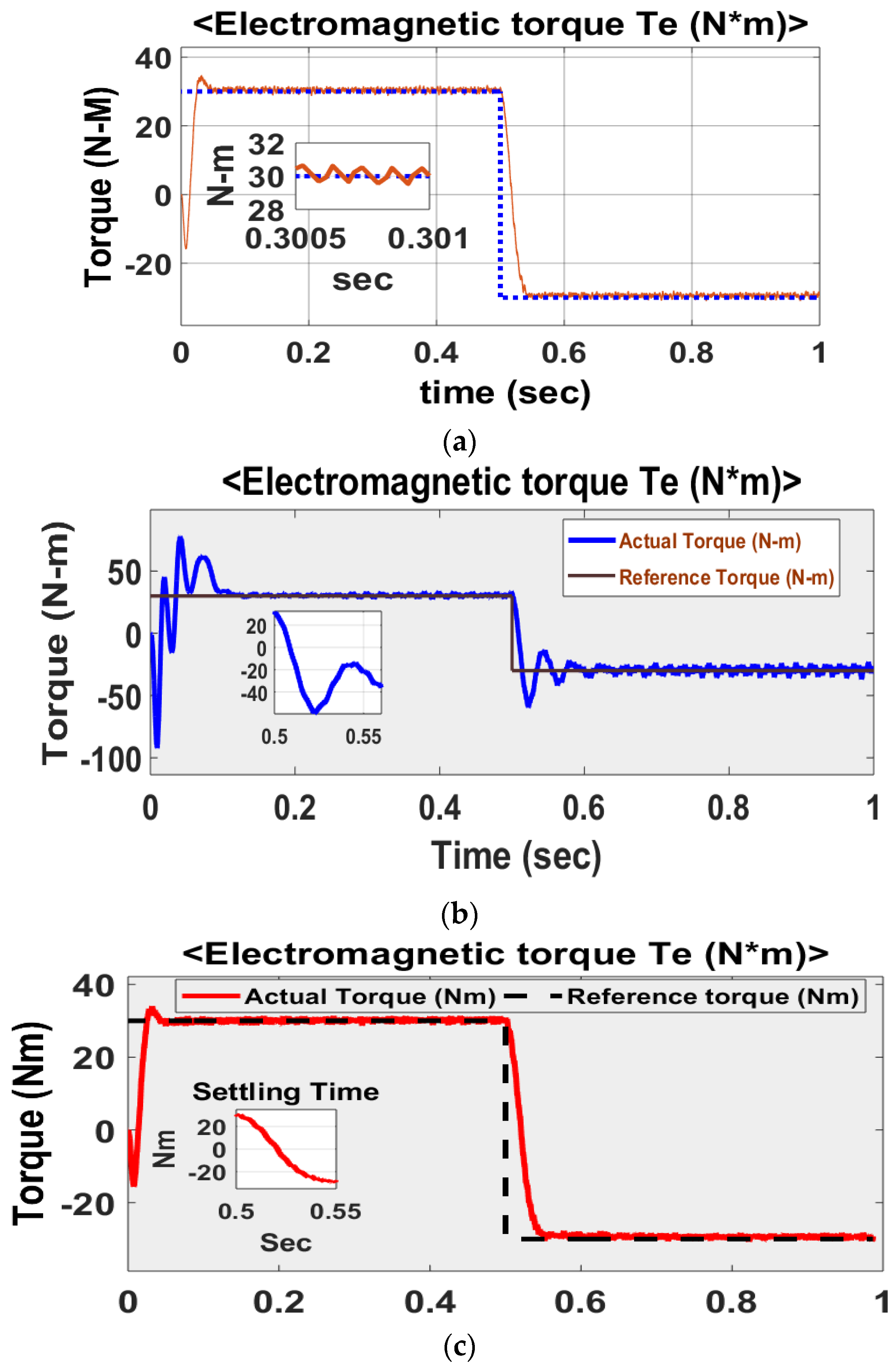
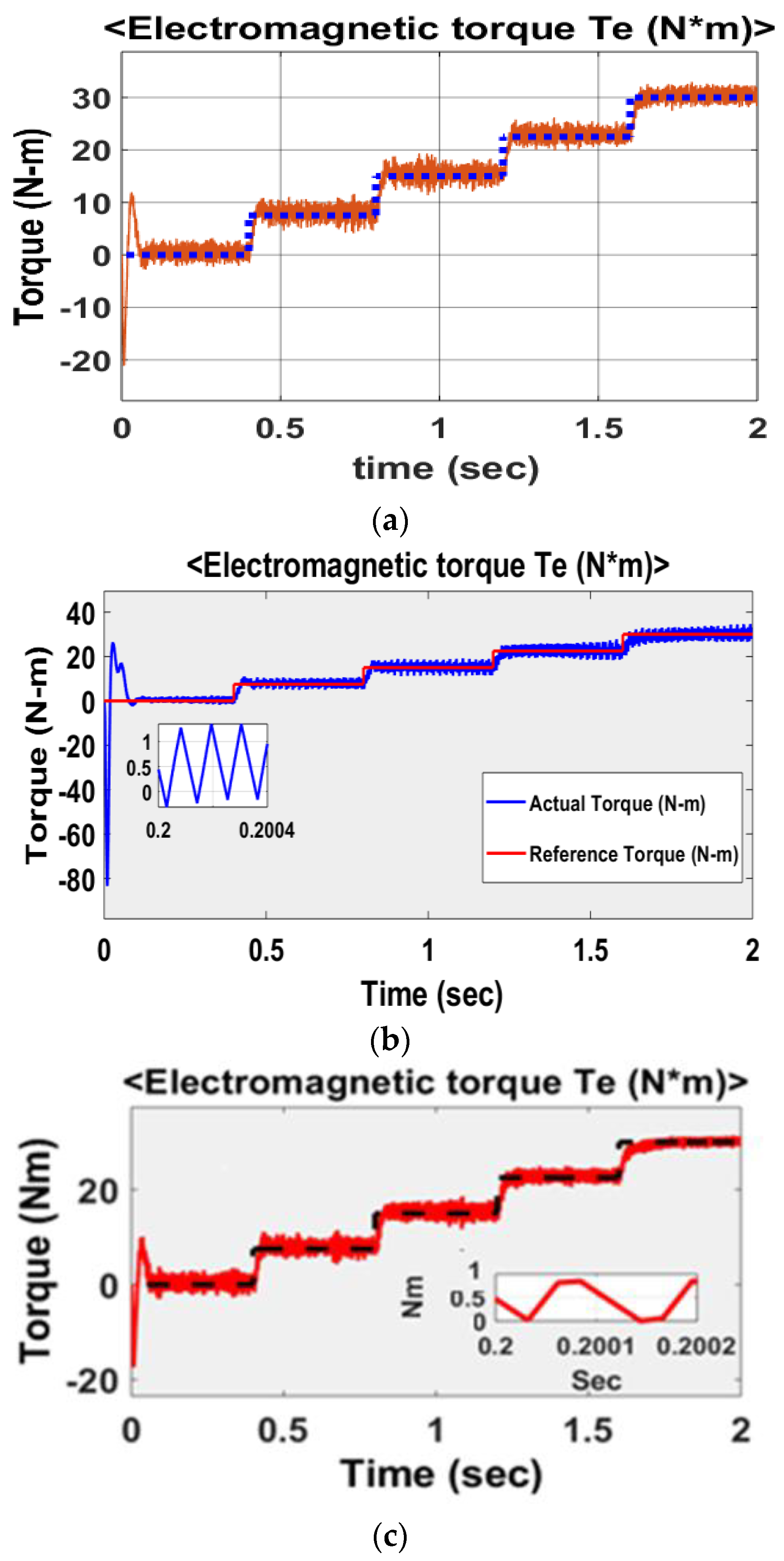
  • Improved system response times during load-changing conditions;
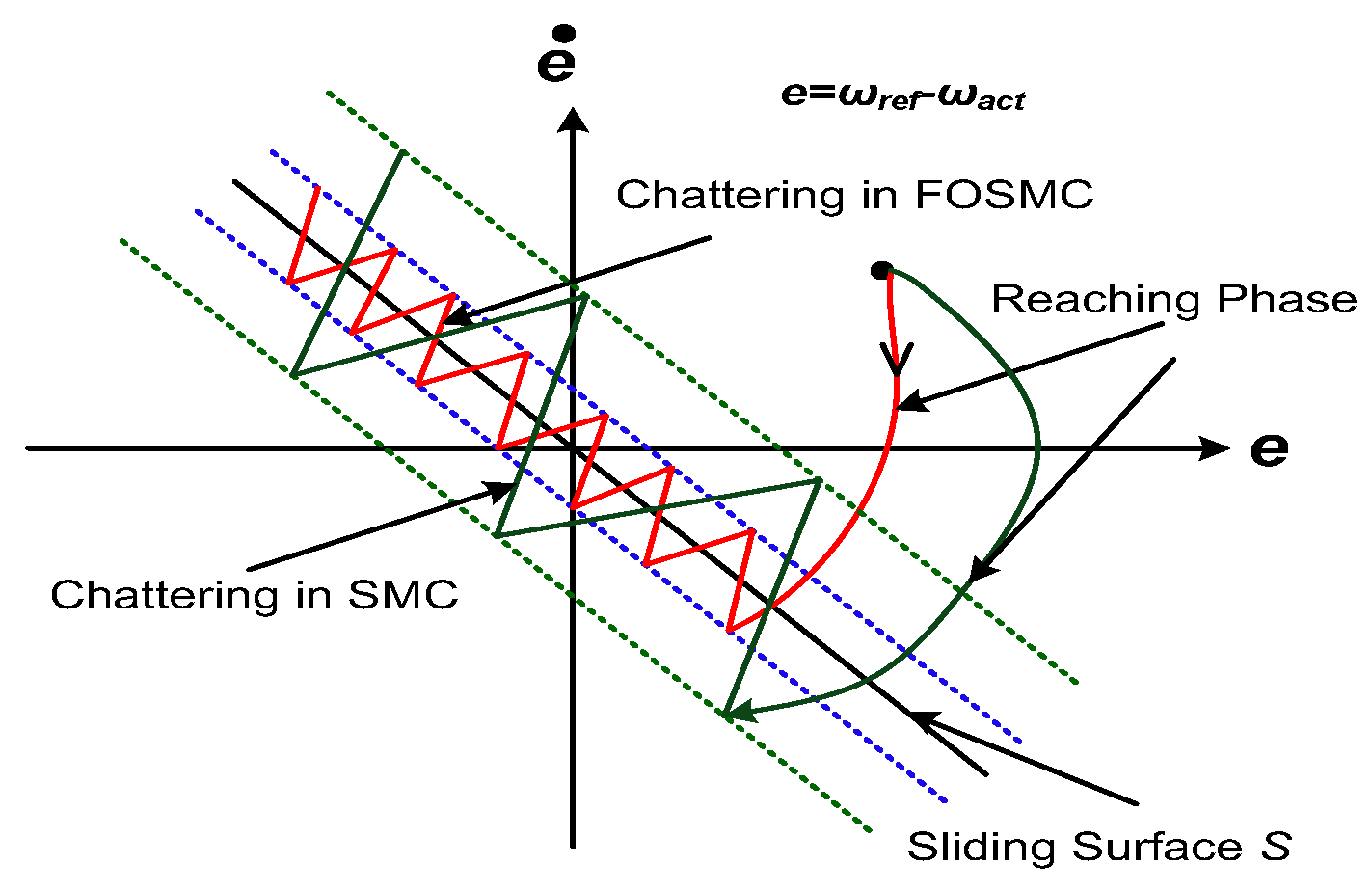
  • Reduction of high-frequency chattering phenomenon;
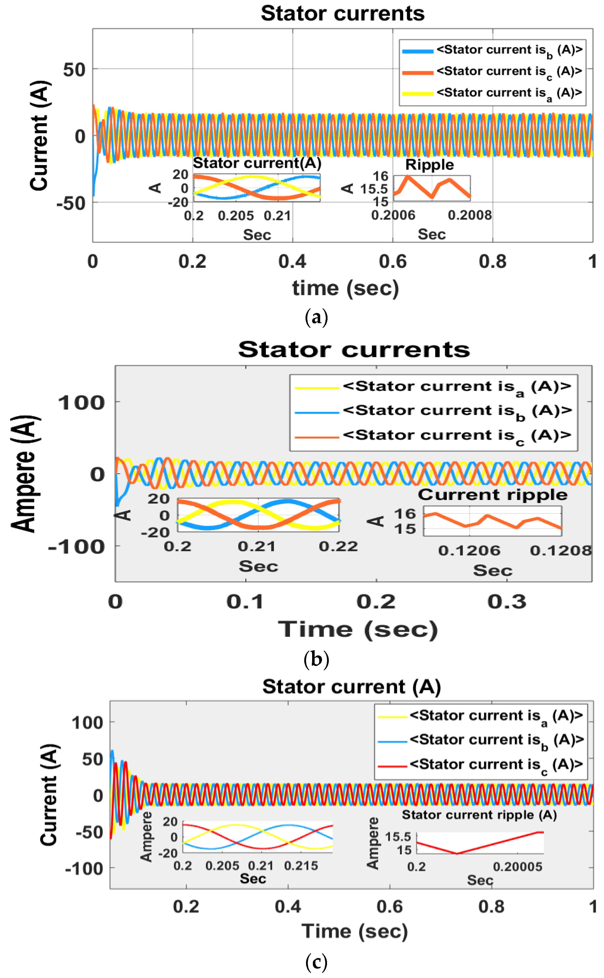
  • Pure sinusoidal stator current waveform with fewer distortions in a 3-Φ IMD;
  • Comparative analysis of the FOSMC-DTC, classical SMC, and PI controller methods.
Section 2.1 addresses the SVM-based DTC using a single PI controller. Section 2.2 deals with the SVM-based DTC with a conventional sliding mode controller. Section 2.3 presents the proposed FOSMC-DTC–based SVM of an IMD. The mathematical modeling of an IMD using the FOSMC-DTC scheme is presented in Section 3. Simulation results and discussions are handled in Section 4, with conclusions and future scope in Section 5.

2. Fractional-Order Sliding Mode Controller for Induction Motors

The fractional-order controller has two additional degrees of freedom, which makes it more efficient in handling nonlinearities compared to the classical PID controller. The sliding mode control strategy is a robust nonlinear control technique derived from variable structure control to overcome the disadvantages of modeling uncertainties and disturbances of nonlinear control techniques. The space vector–modulated DTC scheme permits effective speed control over other classical schemes, such as field-oriented or conventional DTC, with better steady-state and dynamic torque response with fewer ripples. Hence, in the present work, a fractional order–based sliding mode control strategy is proposed for SVM-based direct torque control of induction motors. Initially, the SVM-based direct torque control using a conventional PI controller is discussed, and later, the concept of sliding mode control strategy is presented. Finally, the proposed fractional order–based sliding mode control methodology for induction motors is presented.

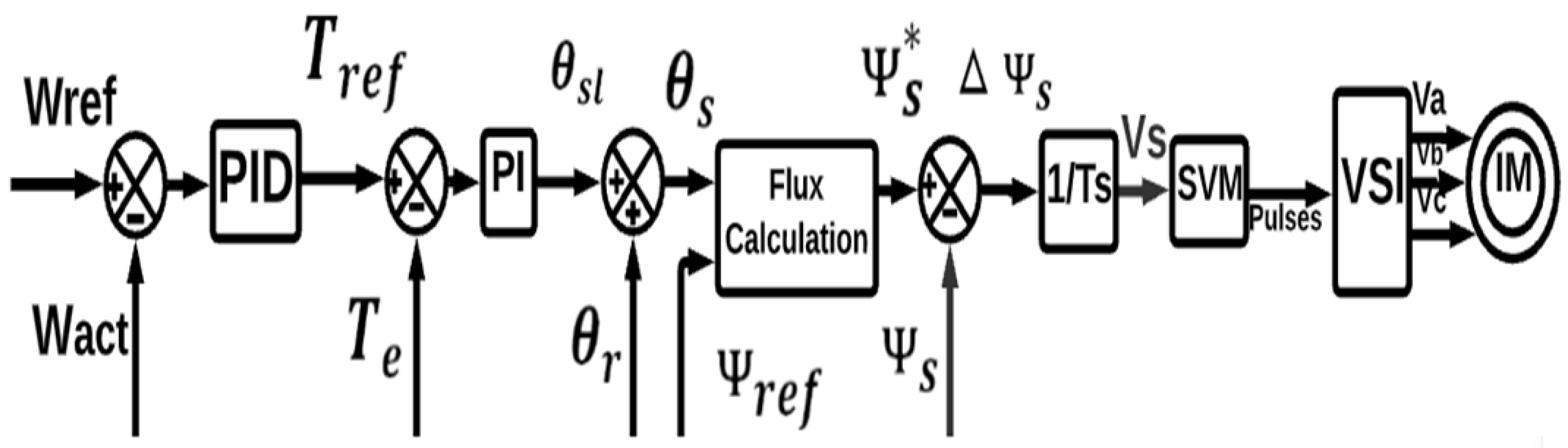
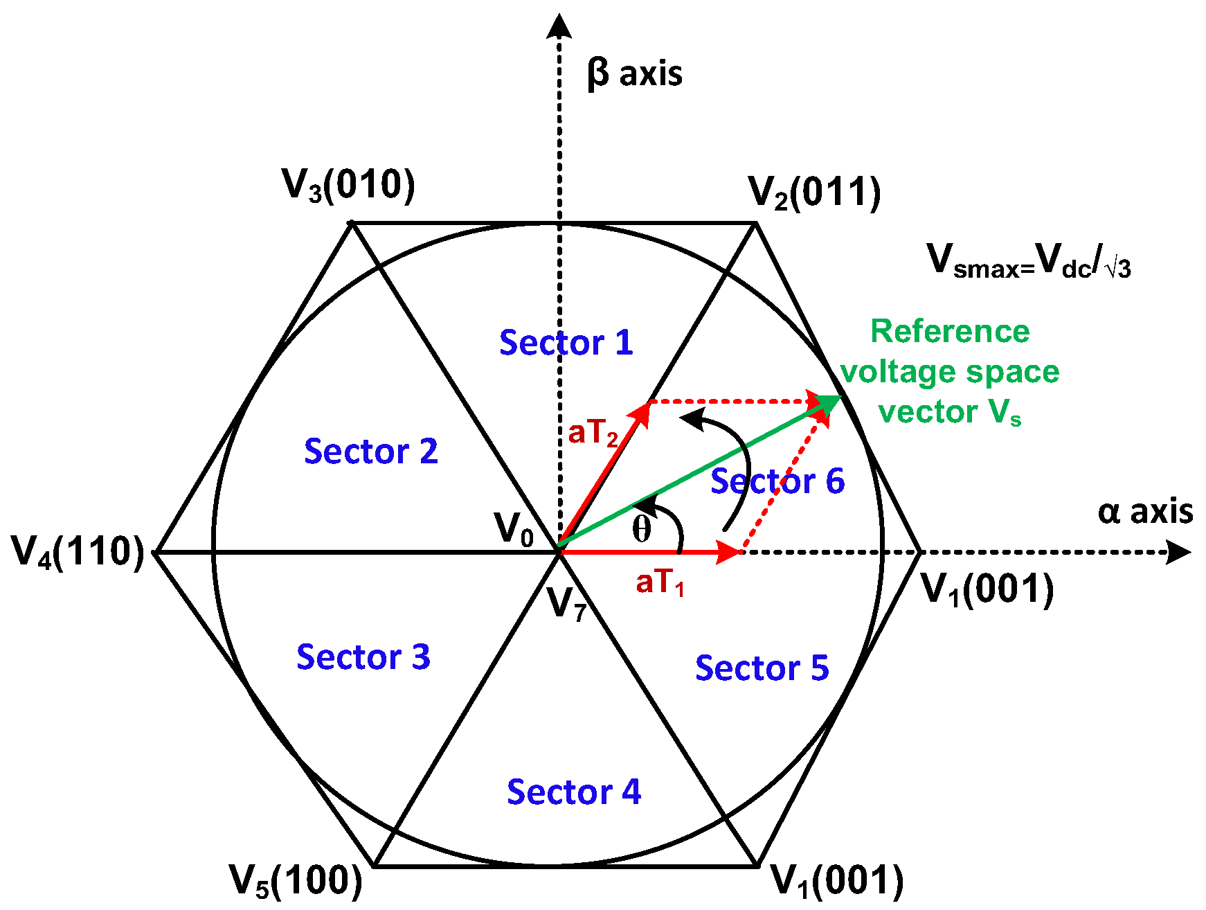
2.1. SVM-Based DTC Using Single PI Controller

In space vector pulse width modulation using the reference voltage space vector, the pulse width of the inverter switches is modulated. The synthesization of the reference voltage space vector is achieved using three stationary voltage vectors. The switching frequency of this scheme operates at a constant, unlike other PWM techniques with lower current and low torque ripple. It can be applicable to high-power applications.
Figure 1 shows the complete block diagram of a DTC-SVM control scheme using a single PI controller [8]. The reference and actual speeds are compared, and its output is given to a PID controller to generate the reference torque. The reference torque and estimated torque are compared, its output is passed through a PI controller, and a slip angle is generated. The induction motor rotor angle is added to the slip angle to obtain the reference stator angle. The stator angle and reference flux are used to calculate the complex form of the stator flux, and the complex form is then converted to a polar form. The flux deviation multiplied by the switching frequency yields the reference voltage space vector.

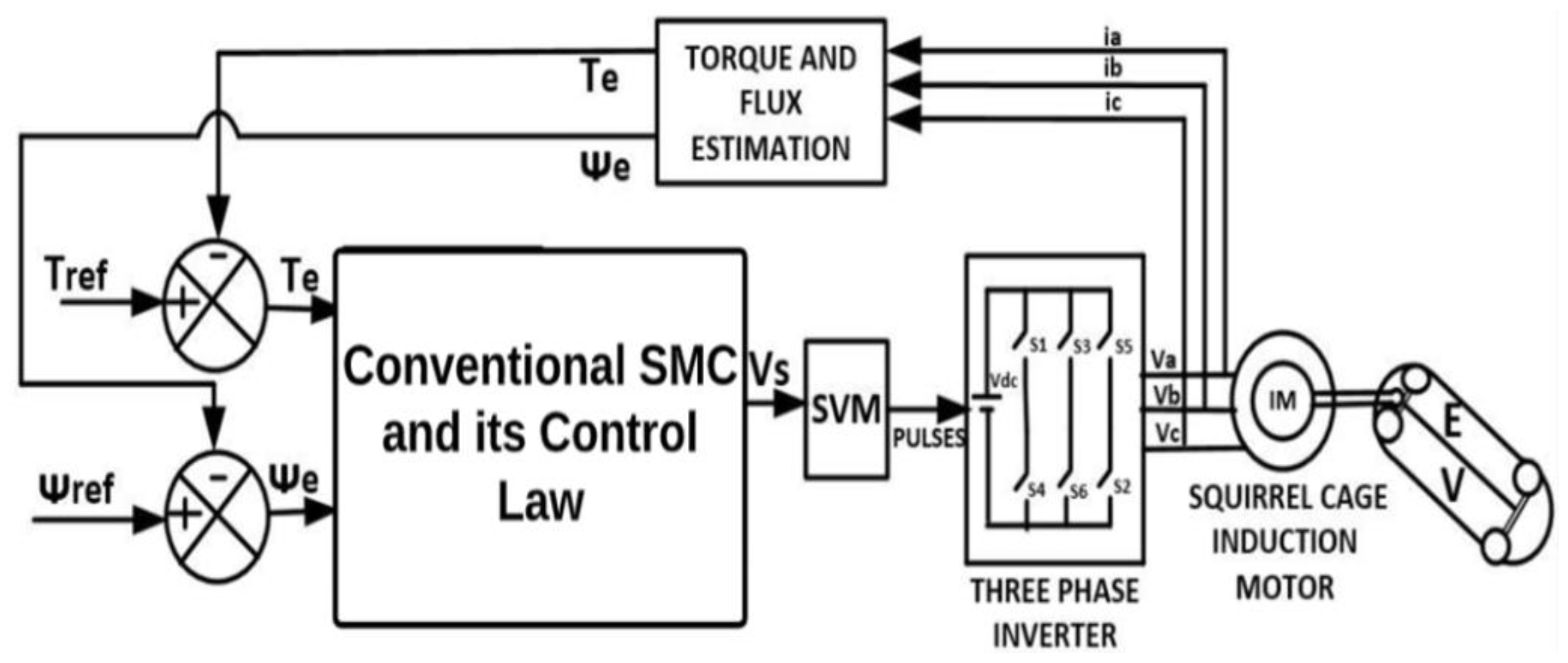
2.2. SVM-Based DTC with Conventional Sliding Mode Controller

A sliding mode controller (SMC) is a more dynamic and robust controller compared to a PI or hysteresis controller in tracking a given reference variable. DTC with SVM using a conventional SMC consists of a sliding mode controller block with its control law, SVPWM block, two-level inverter, and actual torque and flux estimation. In this, the reference space voltage vector is derived using two separate linear sliding surfaces with their control law. Having defined the sliding surface (s) for torque and flux, a signum function is used, as shown in Equation (1). The reference voltage is given to the SVM block for generating pulses to the two-level inverter switches. Figure 2 shows the block diagram of DTC-SVM with a conventional sliding mode controller [15].
s i g n s = + 1   i f   s > 0 1   i f   s < 0
The system operates in the sliding mode if Equation (1) satisfies the existence conditions s g > 0 when s < 0 and s g < 0 when s > 0. The stability analysis can be obtained using the Lyapunov function given in Equation (2).
v t = 1 2 s 2 t + 1 2 ( s g t ) 2
In Equation (2), s(t) and s g t are the sliding surface and gradient of the sliding surface, respectively.

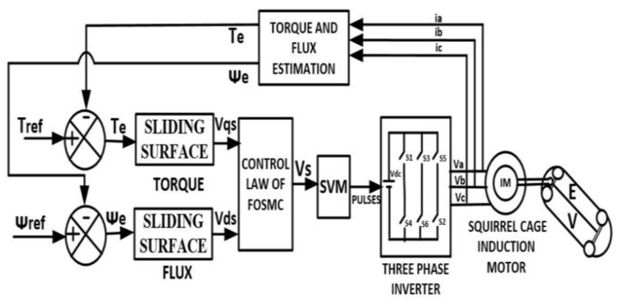
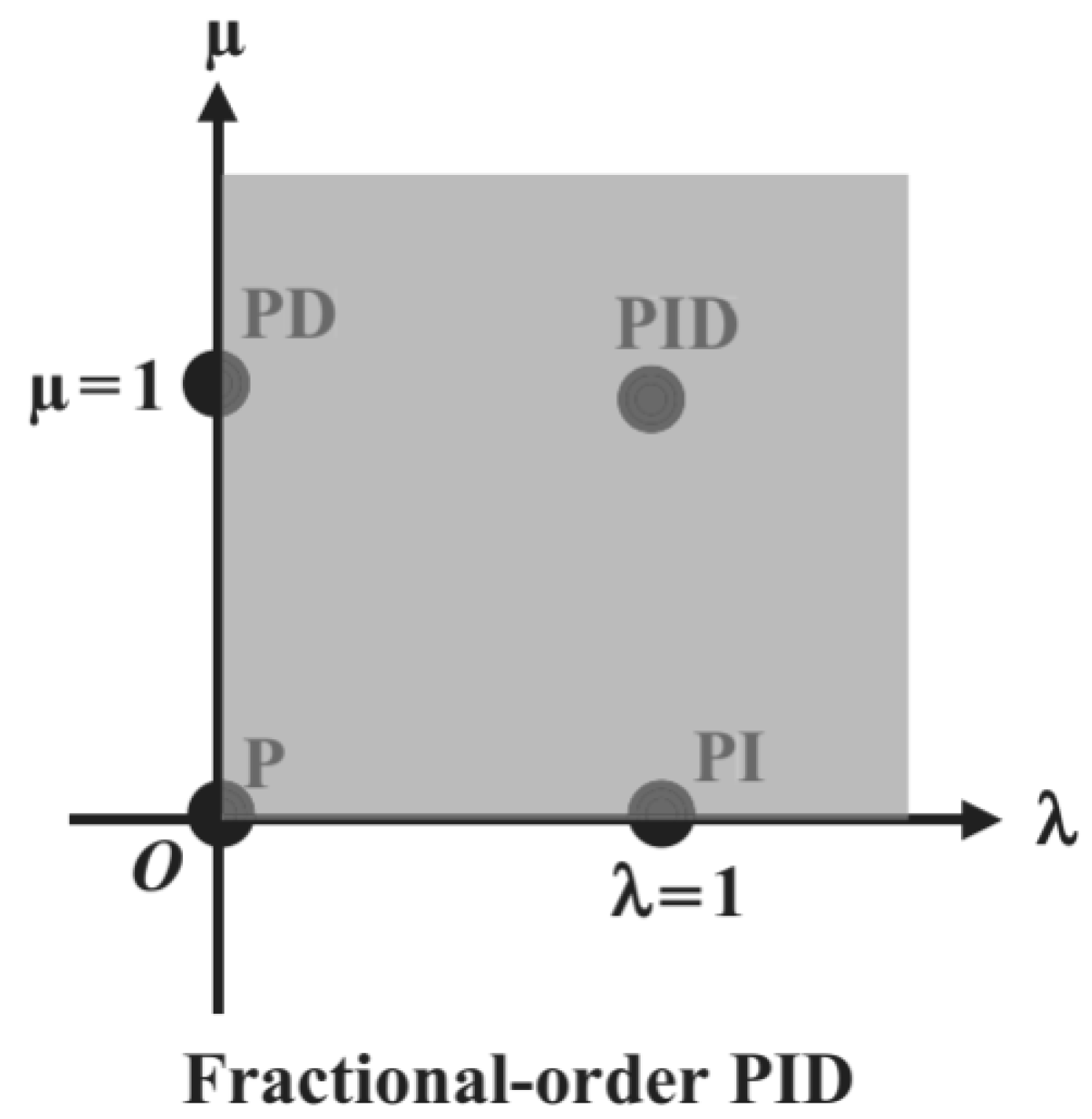
2.3. SVM-Based FOSMC-DTC of Induction Motors

A more robust and optimal control implementation than the SMC is obtained using fractional-order controllers (FOSMCs). The control efforts and best performance can be obtained using this algorithm. Since the power converters are inherently variable structure systems, these algorithms can be implemented effectively. These controllers use fractional-order differentiators/integrators. Keeping the main benefits of an SMC intact, an optimal dynamic response can be obtained using FOSMCs. These are widely used in sensorless vector-controlled induction motor drives, wind energy systems, lighting control systems, and photovoltaic systems.
The proposed FOSMC-DTC scheme consists of flux and torque controllers based on an FOSMC, SVPWM block, actual flux, and torque estimator, and the block diagram is shown in Figure 3. In this control technique, the reference and actual torques and reference and actual fluxes are given to the torque and flux comparators, respectively. The errors generated through torque and flux are applied as input to the torque and flux fractional-order sliding mode controllers. These are designed based on PID controllers. The reference space vector voltage is calculated and given to the SVM block to generate the switching pulses to the IGBT switches of the inverter circuit.
Compared to the conventional SMC, the presented FOSMC-DTC is very robust against external perturbations. The operation is performed at 5 kHz to obtain reduced flux and torque ripple content. This work reduces high-frequency chattering with fractional-order sliding surfaces and takes less reaching time for the sliding variables to reach the origin. The stability of the system can be realized well using an FOSMC. This work best utilizes the stator flux and reduces the settling times of the torque response during load changes. Figure 4 shows the high-frequency oscillations leading to chattering in the SMC and FOSMC [15,18]. The FOSMC reducing the chattering effect compared to the SMC is presented.
From Figure 4, it can be observed that the chattering effect is significantly reduced in the case of the FOSMC compared to the PI controller and conventional SMC. Hence, this fractional sliding mode controller is best suited for the speed control of induction motor drive applications, where the objective is to obtain smaller torque ripples during the low-speed operation of the EV under perturbations. Therefore, this theoretical knowledge from the FOSMC is well explored and applied in this work.
Figure 5 [25,33] shows the SVPWM sectors diagram. Sectors of operation in the proposed DTC scheme in the α, β coordinate system attached to the stator fixed reference frame are shown in Figure 5.

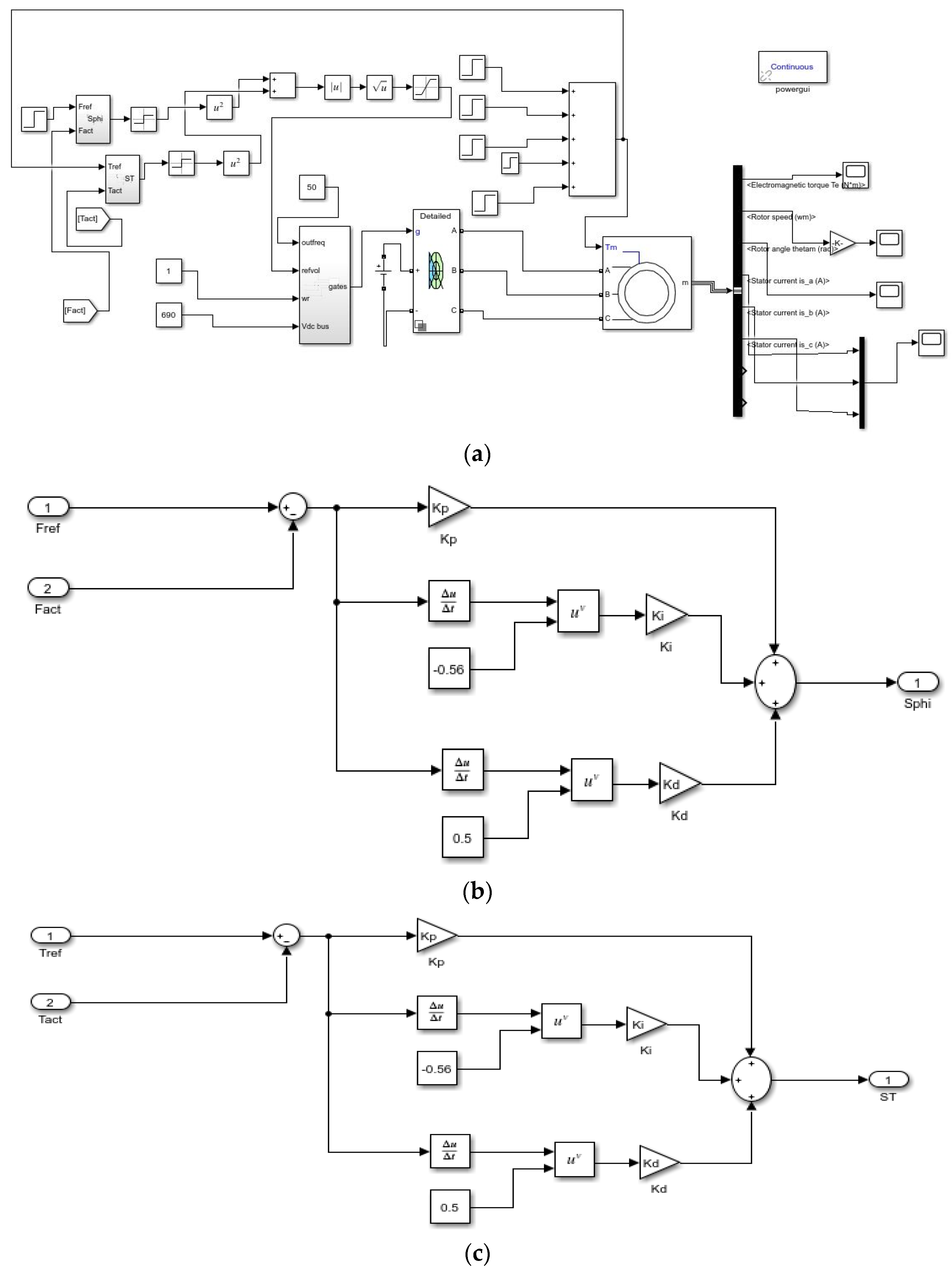
3. Mathematical Model of FOSMC-DTC Scheme of IMD

In the DTC scheme, the simultaneous control of torque and stator flux linkage is obtained by generating a reference voltage space vector to the induction motor through a three-phase voltage source inverter (VSI) circuit. The derivation of this reference voltage vector depends on the flux linkage and torque errors. A PID-derived sliding surface is assumed in this work. Therefore, the sliding surfaces S T and S ψ for the torque and flux in the FOSMC-DTC are given in Equations (3) and (4).
S T = K P e T + K I D λ e T + K D D u e T
S ψ = K P e ψ + K I D λ e ψ + K D D u e ψ
where KP, KI, and KD are the proportional, integral, and derivative constants, respectively.
Differentiate Equations (3) and (4) to obtain Equations (5) and (6), respectively.
S T g = K P e T g + K I D λ   e T g + K D D u e T g  
S ψ g = K P e ψ g + K I D λ   e ψ g + K D D u e ψ g  
where S T g and S ψ g are the surface gradients of the torque and flux control techniques, respectively.
The control law of the FOSMC-DTC scheme is given in Equation (7).
U = K   s g n s g
The derivation for the electromechanical torque follows in the DTC-FOSMC control scheme. The sliding surface for the FOSMC-based DTC is given by Equation (8).
S = K P e + K I D λ   e + K D D u e
where u and λ are the fractional-order derivative and integral constant, respectively, and the error speed e is given in Equation (7).
e = ω r e f ω a c t
where ωref is the desired speed and the actual speed of the three-phase induction motor is ωact. The first-order derivative for the sliding surface given in Equation (8) is given in Equation (10).
S g = K P e g + K I D λ   e g + K D D u e g
According to convergence law, the derivative of the sliding surface is given in Equation (11).
S g = K   s g n S
After substituting Equation (10) into Equation (11) and resolving, we obtain an expression for the derivative of the speed error, which is given in Equation (12).
e g = 1 K P + K D   D μ K I D λ e + K   s g n   S
The derivative of the speed error e g is given in Equation (13).
e g = ω   r e f   g ω   a c t   g
Substituting Equation (13) into Equation (12), we obtain Equation (14).
ω   r e f   g ω   a c t   g = 1 K P + K D   D μ K I D λ e + K   s g n   S
The actual rotor speed ω   a c t   g is given in Equation (15).
ω   a c t   g = 1 J   T e m T L B ω  
After substituting Equation (13) into Equation (14) and resolving the expressions, the electromechanical torque is obtained and given in Equation (16).
T e m = ( T L + B ω ) + J [ ω   r e f   g + 1 K P + K D   D u K I D λ ω r e f ω a c t + K   s g n   S ]
In this work, for 5 kHz switching frequency operation, the step angle obtained is 4 degrees and is shown in Equation (17).
Δ α = 360   f f s

4. Simulation Results and Discussions

The induction motors incorporated in EVs require higher dynamic performance and smooth control under different load and road disturbance conditions, and hence, they require efficient control strategies to operate with less torque and flux ripples compared to conventional methods. Hence, in the present work, a fractional order–based sliding mode control strategy is proposed for the SVM-based direct torque control of induction motors.
The proposed DTC-SVM with fractional-order sliding control is simulated using MATLAB/Simulink. Table 1 shows the induction motor specifications [25].
The FOSMC-based PID controller has two additional degrees of freedom, which make it more efficient than the classical PID controller, although the tuning of the parameters is complicated. Soft computing algorithms, such as GA, PSO, and other techniques, can be used to locate the parameters λ and u of the controller, but they are computationally laborious. In this work, using the Euclidean plane [18,29], as shown in Figure 6, is followed to determine the controller parameters. A classical PID controller is obtained from a fractional-order PID controller if λ = 0 and u = 1. Similarly, a PI controller is obtained when λ = 1 and u = 0. A proportional controller is obtained if λ = 0 and u = 0. Hence, it very clear that numerous control structures can be defined accurately by properly selecting the values of λ and u. In this work, at low torque ripple and operation in which speed and torque errors are minimized for effective speed control and low output torque ripple at low voltage levels for an EV, the range of λ and u are taken as 0.45 to 0.56 for effective tracking and smooth control following the Euclidean plane.
Table 2 shows the controller parameters used for simulation work.
Figure 7 represents the complete simulation diagram of the proposed work. Figure 7a represents the MATLAB Simulink diagram of FOSMC-DTC Scheme. The generation of flux and torque sliding surfaces using MATLAB Simulink is presented in Figure 7b,c. To show the uniqueness of the proposed FOSMC controller, it is compared with DTC-SVM with a single PI controller [8] and conventional SMC [15]–based DTC-SVM. Steady-state speed response and its ripple content at rated torque of 30 Nm are shown for all three schemes in Figure 8a–c.
From Figure 8a–c, it can be observed that the proposed FOSMC-DTC scheme produces a smaller speed ripple of 1.5 rpm, whereas the PI and SMC schemes produce 2 and 1.8 rpm ripples, respectively.
The induction motor drive is operated at 30 N-m to observe torque ripple for all three control schemes. Steady-state torque response and its ripple content at a rated torque of 30 Nm are shown for all three schemes in Figure 9.
Figure 9a–c indicates that the proposed control FOSMC scheme produces a smaller torque ripple of 1 N-m, whereas the PI and SMC schemes produce 2 and 1.8 N-m, respectively.
For a sudden load change, the drive is initially operated at a rated torque of 30 Nm for 0.45 s; then the drive is commanded to reverse its torque from 30 to −30 N-m at 0.45 s until the time reaches 1 s. The transient response and its settling times are shown for all three schemes in Figure 10.
From Figure 10, it can be observed that, for the sudden step change in torque, the proposed FOSMC has better tracking of torque with less torque ripple and shorter settling times. From Figure 10a–c, it can be said that the proposed FOSMC-DTC has a minimum response time of 5 ms during load change conditions, where it is 6 and 5.5 ms with the single PI controller and conventional SMC schemes, respectively.
The dynamic response of the ©nduction motor for a torque step change of 7.5 Nm for every 0.4 s from no load to full load is shown for all three schemes in Figure 11.
Figure 11 shows the dynamic response of torque obtained for a step change of torque from no load to full load conditions. It is observed that using DTC-SVM with an FOSMC gives better results in terms of tracking the actual torque trajectory with very little torque ripple content, as shown in Figure 11c.
Three-phase stator currents of an induction motor and its ripple are shown for all three schemes in Figure 12.
Figure 12c reveals that the proposed scheme has a lower stator current ripple of about 0.5 A, where DTC-SVM with a single PI controller or SMC generates 2 A or 1 A, as shown in Figure 12a,b, respectively.
Flux trajectory and its utilization at a rated torque of 30 Nm are shown for all three schemes in Figure 13.
Flux trajectories obtained at rated torque are shown in Figure 13, and it can be observed clearly that the reduction in the chattering effect is much better in the FOSMC compared to the PI controller and conventional SMC. From Figure 13a,b, it can be observed that the single PI and conventional SMC techniques utilize 0.55 wb-t and 0.54 wb-t stator flux linkages, respectively. Figure 13c shows that the FOSMC-DTC scheme utilizes only 0.5 wb-t stator flux linkages. The flux ripples take longer steps to reach the reference value of flux in the case of PI and classical SMC techniques, whereas using FOSMC, it is found that it takes only a single step to reach the reference flux value of 0.5 Wb-t. From this, it is very clear that the FOSMC-based DTC of an induction motor drive, particularly for EVs, presents high performance, especially at low speeds. The effective utilization of the flux linkages is realized using this controller.
Figure 14 shows the harmonic spectrum of stator current for all three schemes.
Figure 14c shows the proposed scheme as 4.72% THD, whereas DTC-SVM with a single PI controller as 13.85% THD is shown in Figure 12a,b.
Flux linkage and its corresponding ripple content at rated torque of 30 Nm are shown for all three schemes in Figure 15.
Figure 15c indicates the proposed scheme has a lower flux ripple of about 0.006 wb, whereas DTC-SVM with a single PI controller or SMC generates 0.01 wb or 0.008 wb, as shown in Figure 13a,b, respectively.
Table 3 shows steady-state torque ripples with the conventional PI, SMC, and the proposed FOSMC-DTC schemes at full and one-fourth load conditions, and Table 4 shows the settling times of torque responses during transient conditions. From Table 3 and Table 4, it can be said that the proposed FOSMC is much better compared to the conventional PI controller and SMC in reducing the torque ripples and improving the settling times. From the above simulation results, it can be concluded that the proposed fractional-order sliding mode controller reduced the steady-state torque, flux, current, and speed ripples and improved the settling times during transient conditions compared to the conventional PI and SMC schemes. The proposed FOSMC scheme has the advantage of the best utilization of the required stator flux and reduced the total harmonic distortion from 13.85 to 4.72 percent as compared with DTC-SVM single PI controller.
Figure 16 shows the torque response for the step change of slip angle θs. For three different slip angles, torque response plots are obtained. Figure 16 shows that torque increases at a rate proportional to the step change in dθs/dt until reaching maximum torque, and it attains a maximum torque value at s/dt = 2 × π × 22.7. For lower values of speed, torque increases at a slower rate when compared with high-speed values. Therefore, the DTC-FOSMC exhibits a robust behavior when compared to DTC-SVM with the single PI controller and conventional SMC.

5. Conclusions

In this paper, a fractional-order sliding mode control scheme is proposed for SVM-based DTC to overcome the drawbacks associated with PI and other classical sliding mode controllers during transient conditions. This work presents a DTC-FOSMC for a two-level inverter-fed induction motor drive (IMD) operating at a fixed switching frequency of 5 kHz, which finds applications in electric vehicles (EVs). It is observed that, with the proposed FOSMC scheme, flux errors and torque errors are minimized when compared to the PI controller and conventional SMC, while reducing high-frequency chattering with shorter settling times. The implementation of space vector modulation in the FOSMC-DTC scheme has several advantages, including smooth rotating voltage space vector at higher switching frequencies (5 kHz), reduced torque ripples (1 Nm), reduced speed ripples (1.5 rpm), shorter settling times (5 ms) during transient conditions, and lower total harmonic distortion (THD) of the stator current (4.72%). A comparison is also presented with the PI controller and SMC to highlight the need for an FOSMC for DTC in electric vehicles. Hence, this control scheme can be effectively used for the speed control of an IMD in an EV, particularly at low speeds. However, the design and tuning of fractional-order sliding mode controller make it very difficult to obtain optimal values for stability, and a wide future scope is in the application of machine learning algorithms for further improving the proposed control scheme.

Author Contributions

Conceptualization, S.K.G.; formal analysis, S.K.G., M.M. and K.J.; methodology, S.K.G.; software, M.M.; validation, S.K.G. and S.R.G.; writing—original draft, S.K.G. and M.M.; writing—review & editing, S.K.G. and S.R.G. All authors have read and agreed to the published version of the manuscript.

Funding

This research was funded by AICTE, New Delhi, India, under the research promotion scheme.

Data Availability Statement

Not applicable.

Conflicts of Interest

The authors declare no conflict of interest.

Abbreviations

BLDCBrushless DC motor
DTCDirect torque control
EVElectric vehicle
SPWMSpace vector pulse width modulation
SVMSpace vector modulation
PIProportional and integral
SMCSliding mode controller
HOSMCHigher-order sliding mode controller
FOSMCFractional-order sliding mode controller
IMDInduction motor drive
PMSMpermanent magnet synchronous motor drive
SRMSwitched reluctance motor
PIDProportional-integral controller
SSliding surface
s g Surface gradient
uFractional-order derivative gain
λFractional-order integral gain.
ω r e f Desired speed
ω a c t Actual speed
S T g Surface gradient of torque control
S ψ g Surface gradient of flux control
T e m Electromechanical torque
T L Load torque

References

  1. Qianfan, Z.; Shumei, C.; Xinjia, T. Hybrid Switched Reluctance Motor Applied in Electric Vehicles. In Proceedings of the 2007 IEEE Vehicle Power and Propulsion Conference, Arlington, TX, USA, 9–12 September 2007; pp. 359–363. [Google Scholar]
  2. Kang, J.K.; Chung, D.W.; Sul, S.K. Direct Torque Control of Induction Machine with Variable Amplitude Control of Flux and Torque Hysteresis Bands. In Proceedings of the IEEE International Electric Machines and Drives Conference IEMDC’99, Seattle, WA, USA, 9–12 May 1999; pp. 640–642. [Google Scholar]
  3. Casadei, D.; Profumo, F.; Serra, G.; Tani, A. FOC and DTC: Two viable schemes for induction motors torque control. IEEE Trans. Power Electron. 2002, 17, 779–787. [Google Scholar] [CrossRef]
  4. Benchaib, A.; Edwards, C. Induction Motor Control Using Nonlinear Sliding Mode Theory. In Proceedings of the European Control Conference (ECC), Karlsruhe, Germany, 31 August–3 September 1999; pp. 779–784. [Google Scholar]
  5. Kuo-Kai, S.; Li-Jen, S.; Hwang-Zhi, C.; Ko-Wen, J. Flux compensated direct torque control of induction motor drives for low speed operation. IEEE Trans. Power Electron. 2004, 19, 1608–1613. [Google Scholar]
  6. Zhuang, S.; He, Y.; Wang, S. Fuzzy Sliding-Mode Speed Control with Torque Observer in Induction Motor Drive. In Proceedings of the 2006 6th World Congress on Intelligent Control and Automation, Dalian, China, 21–23 June 2006; pp. 8260–8264. [Google Scholar]
  7. Peng, K.; Zhao, J. Speed Control of Induction Motor Using Neural Network Sliding Mode Controller. In Proceedings of the 2011 International Conference on Electric Information and Control Engineering, Wuhan, China, 15–17 April 2011; pp. 6125–6129. [Google Scholar]
  8. Hiba, H.; Ali, H.; Othmen, H. DTC-SVM Control for Three Phase Induction Motors. In Proceedings of the 2013 International Conference on Electrical Engineering and Software Applications, Hammamet, Tunisia, 2–23 March 2013; pp. 1–7. [Google Scholar]
  9. Sung, G.; Lin, W.; Peng, S. Reduction of Torque and Flux Variations Using Fuzzy Direct Torque Control System in Motor Drive. In Proceedings of the 2013 IEEE International Conference on Systems, Man, and Cybernetics, Manchester, UK, 13–16 October 2013; pp. 1456–1460. [Google Scholar]
  10. Xing, Z.; Hong, Z.; Fei, L.; Fang, L.; Chun, L.; Benxuan, L. An LCL-LC Power Filter for Grid-Tied Inverter. In Proceedings of the TENCON IEEE Region 10 Conference, Xi’an, China, 22–25 October 2013; pp. 1–4. [Google Scholar]
  11. Zhao, S.; Yu, H.; Yu, J.; Shan, B. Induction Motor DTC Based on Adaptive SMC and Fuzzy Control. In Proceedings of the 27th Chinese Control and Decision Conference, Qingdao, China, 23–25 May 2015; pp. 4474–4479. [Google Scholar]
  12. Yang, Z.; Shang, F.; Brown, I.P.; Krishnamurthy, M. Comparative Study of Interior Permanent Magnet, Induction, and Switched Reluctance Motor Drives for EV and HEV Applications. IEEE Trans. Transp. Electrif. 2015, 1, 245–254. [Google Scholar] [CrossRef]
  13. Ammar, A.; Bourek, A.; Benakcha, A. Implementation of Robust SVM-DTC for Induction Motor Drive Using Second Order Sliding Mode Control. In Proceedings of the 2016 8th International Conference on Modelling, Identification and Control (ICMIC), Algiers, Algeria, 15–17 November 2016; pp. 338–343. [Google Scholar]
  14. Niu, F.; Han, Z.; Xu, W.; Huang, X.; Zhang, J.; Wu, L.; Fang, Y. A Simple Duty Cycle Modulated Direct Torque Control for Permanent Magnet Synchronous Motors. In Proceedings of the 20th International Conference on Electrical Machines and Systems, Sydney, Australia, 11–14 August 2017; pp. 1–4. [Google Scholar]
  15. Oukaci, A.; Toufouti, R.; Dib, D.; Atarsia, L. Comparison performance between sliding mode control and Nonlinear Control, Application to Induction Motor. Electr. Eng. 2017, 99, 33–45. [Google Scholar] [CrossRef]
  16. Wang, D.; Yuan, T.; Liu, Z.; Li, Y.; Wang, X.; Tian, W.; Miao, S.; Liu, J. Reduction of Torque and Flux Ripples for Robot Motion Control System Based on SVM-DTC. In Proceedings of the 37th Chinese Control Conference (CCC), Wuhan, China, 25–27 July 2018; pp. 5572–5576. [Google Scholar]
  17. Alsofyani, I.M.; Idris, N.R.N.; Lee, K. Dynamic Hysteresis Torque Band for Improving the Performance of Lookup-Table-Based DTC of Induction Machines. IEEE Trans. Power Electron. 2018, 33, 7959–7970. [Google Scholar] [CrossRef]
  18. Kumar, V.; Ali, I. Fractional order sliding mode approach for chattering free direct power control of DC/AC converter. IET Power Electron. 2019, 12, 3600–3610. [Google Scholar] [CrossRef]
  19. Babes, B.; Boutaghane, A.; Hamouda, N.; Mezaache, M. Design of a Robust Voltage Controller for a DC-DC Buck Converter Using Fractional-Order Terminal Sliding Mode Control Strategy. In Proceedings of the International Conference on Advanced Electrical Engineering, Algiers, Algeria, 19–21 November 2019; pp. 1–6. [Google Scholar]
  20. Saheb, S.; Gudey, S. Robust fractional order sliding mode control for solar based DC-AC inverter. J. Energy Syst. 2020, 4, 161–178. [Google Scholar] [CrossRef]
  21. Lascu, C.; Argeseanu, A.; Blaabjerg, F. Supertwisting Sliding-Mode Direct Torque and Flux Control of Induction Machine Drives. IEEE Trans. Power Electron. 2020, 35, 5057–5065. [Google Scholar] [CrossRef]
  22. Munoz-Hernandez, G.A.; Mino-Aguilar, G.; Guerrero-Castellanos, J.F.; Peralta-Sanchez, E. Fractional Order PI-Based Control Applied to the Traction System of an Electric Vehicle (EV). Appl. Sci. 2020, 10, 364. [Google Scholar] [CrossRef]
  23. Masoumkhani, H.; Taheri, A. PI Regulator-Based Duty Cycle Control to Reduce Torque and Flux Ripples in DTC of Six-Phase Induction Motor. IEEE J. Emerg. Sel. Top. Power Electron. 2021, 9, 354–370. [Google Scholar] [CrossRef]
  24. Sami, I.; Ullah, S.; Basit, A.; Ullah, N.; Ro, J.S. Integral Super Twisting Sliding Mode Based Sensorless Predictive Torque Control of Induction Motor. IEEE Access 2020, 8, 186740–186755. [Google Scholar] [CrossRef]
  25. Malla, M.; Gudey, S.K.; Sudha, S. Transient and Steady State Characteristics of Induction Motor Drive Using DTC-SVM Technique for EV Applications. In Proceedings of the 11th International Conference on Electrical and Computer Engineering (ICECE), Dhaka, Bangladesh, 17–19 December 2020; pp. 403–406. [Google Scholar]
  26. Xu, W.; Ali, M.M.; Elmorshedy, M.F.; Allam, S.M.; Mu, C. One Improved Sliding Mode DTC for Linear Induction Machines Based on Linear Metro. IEEE Trans. Power Electron. 2021, 36, 4560–4571. [Google Scholar] [CrossRef]
  27. Delavari, H.; Veisi, A. Robust Control of a Permanent Magnet Synchronous Generators based Wind Energy Conversion. In Proceedings of the 7th International Conference on Control, Instrumentation and Automation (ICCIA), Tabriz, Iran, 23–24 February 2021; pp. 1–5. [Google Scholar]
  28. Benbouhenni, H.; Bizon, N. Improved Rotor Flux and Torque Control Based on the Third-Order Sliding Mode Scheme Applied to the Asynchronous Generator for the Single-Rotor Wind Turbine. Mathematics 2021, 9, 2297. [Google Scholar] [CrossRef]
  29. Yu, X.; Yi, H.; Mao, Z. Spacecraft Attitude Tracking Control Based on MPC and Fractional-Order Sliding Mode Control. In Proceedings of the 2022 5th International Symposium on Autonomous Systems (ISAS), Hangzhou, China, 8–10 April 2022; pp. 1–6. [Google Scholar]
  30. Shiravani, F.; Alkorta, P.; Cortajarena, J.A.; Barambones, O. An Enhanced Sliding Mode Speed Control for Induction Motor Drives. Actuators 2022, 11, 18. [Google Scholar] [CrossRef]
  31. Kotb, H.; Yakout, A.H.; Attia, M.A.; Turky, R.A.; AboRas, K.M. Speed control and torque ripple minimization of SRM using local unimodal sampling and spotted hyena algorithms based cascaded PID controller. Ain Shams Eng. J. 2022, 13, 101719. [Google Scholar] [CrossRef]
  32. Yang, Z.; Wang, D.; Sun, X.; Wu, J. Speed sensorless control of a bearingless induction motor with combined neural network and fractional sliding mode. Mechatronics 2022, 82, 102721. [Google Scholar] [CrossRef]
  33. De Klerk, M.L.; Saha, A.K. Performance analysis of DTC-SVM in a complete traction motor control mechanism for a battery electric vehicle. Heliyon 2022, 8, e09265. [Google Scholar] [CrossRef] [PubMed]
  34. Wang, T.; Wang, B.; Yu, Y.; Xu, D. Discrete Sliding-Mode-Based MRAS for Speed-Sensorless Induction Motor Drives in the High-Speed Range. IEEE Trans. Power Electron. 2023, 38, 5777–5790. [Google Scholar] [CrossRef]
  35. Adigintla, S.; Aware, M.V. Robust Fractional Order Speed Controllers for Induction Motor under Parameter Variations and Low Speed Operating Regions. IEEE Trans. Circuits Syst. II Express Briefs 2023, 70, 1119–1123. [Google Scholar] [CrossRef]
Figure 1. DTC-SVM using single PI controller.
Wevj 14 00137 g001
Figure 2. DTC-SVM using conventional sliding mode controller.
Wevj 14 00137 g002
Figure 3. FOSMC-DTC control scheme block diagram.
Wevj 14 00137 g003
Figure 4. Chattering phenomenon in fractional-order sliding control (FOSMC) and SMC.
Wevj 14 00137 g004
Figure 5. Sectors of operation in SVM-based DTC scheme.
Wevj 14 00137 g005
Figure 6. Euclidean plane for FOSMC control parameters.
Wevj 14 00137 g006
Figure 7. Simulink diagram of the FOSMC-DTC scheme. (a) Complete block diagram of the FOSMC-DTC scheme; (b) flux sliding surfaces for FOSMC-DTC scheme; (c) torque sliding surfaces for FOSMC-DTC scheme.
Wevj 14 00137 g007
Figure 8. Steady-state speed response and its ripple content at rated torque of 30 Nm. (a) DTC-SVM with single PI controller; (b) conventional SMC–based DTC-SVM scheme; (c) DTC-SVM with FOSMC.
Wevj 14 00137 g008
Figure 9. Steady-state torque response and its ripple content at rated torque of 30 Nm. (a) DTC-SVM with single PI controller; (b) conventional SMC–based DTC-SVM scheme; (c) DTC-SVM with FOSMC.
Wevj 14 00137 g009
Figure 10. Transient response at rated torque reversal of 30 Nm and its settling times. (a) DTC-SVM with single PI controller; (b) conventional SMC–based DTC-SVM scheme; (c) DTC-SVM with FOSMC.
Wevj 14 00137 g010
Figure 11. Dynamic response for step change of 7.5 Nm for every 0.4 s from no load to full load. (a) DTC-SVM with single PI controller; (b) conventional SMC–based DTC-SVM scheme; (c) DTC-SVM with FOSMC.
Wevj 14 00137 g011
Figure 12. Three-phase stator currents of an induction motor and its ripple content in (a) DTC-SVM with single PI controller, (b) conventional SMC–based DTC-SVM scheme, and (c) DTC-SVM with FOSMC.
Wevj 14 00137 g012
Figure 13. Flux trajectory and its utilization at rated torque of 30 Nm. (a) DTC-SVM with single PI controller; (b) conventional SMC–based DTC-SVM scheme; (c) DTC-SVM with FOSMC.
Wevj 14 00137 g013
Figure 14. Harmonic analysis of stator current and its THD in (a) DTC-SVM with single PI controller, (b) conventional SMC–based DTC-SVM scheme, and (c) DTC-SVM with FOSMC.
Wevj 14 00137 g014aWevj 14 00137 g014b
Figure 15. Flux linkage and its corresponding ripple content at rated torque of 30 Nm. (a) DTC-SVM with single PI controller; (b) conventional SMC–based DTC-SVM scheme; (c) DTC-SVM with FOSMC.
Wevj 14 00137 g015aWevj 14 00137 g015b
Figure 16. Torque response for step change of dθs/dt.
Wevj 14 00137 g016
Table 1. Squirrel cage induction motor data [25].
Rating of the Induction Motor, P5.4 HP
Voltage (L-L), Vrms440 V
Power frequency, fs50 Hz
Rated torque, T30 N-m
Rated current (Peak) 16 A
Nominal speed, Nnom1430 rpm
Table 2. Controller parameters used for simulation work.
Controller ParametersFlux Sliding SurfaceTorque Sliding Surface
λ0.50.56
u0.450.5
kP1.55.0
kI0.10.1
kD1.01.0
Table 3. Steady-state torque ripples with PI controller, SMC, and proposed DTC-SVM–based FOSMC at full and one-fourth load conditions.
TorqueTorque Ripple
PI Controller [8]SMC [15]FOSMC
30 Nm2 N-m1.8 N m1 N m
7.5 Nm1.2 N m1 N m0.6 N m
Table 4. Torque response settling times during transient operation.
Load ChangeSettling Times
PI Controller [8]SMC [15]FOSMC
30 to −30 Nm6.0 ms5.5 ms5 ms
7.5 to −7.5 Nm5.8 ms5.4 ms4.8 ms
Disclaimer/Publisher’s Note: The statements, opinions and data contained in all publications are solely those of the individual author(s) and contributor(s) and not of MDPI and/or the editor(s). MDPI and/or the editor(s) disclaim responsibility for any injury to people or property resulting from any ideas, methods, instructions or products referred to in the content.

