Article

Smooth Speed Control of Permanent Magnet Synchronous Machine Using Back Propagation Neural Network

1
School of Electrical and Electronic Engineering, Nanyang Technological University, 50 Nanyang Avenue, Singapore 639798, Singapore
2
School of Electrical and Information, Jiangsu University, Zhenjiang 212013, China
*
Author to whom correspondence should be addressed.
World Electr. Veh. J. 2023, 14(4), 92; https://doi.org/10.3390/wevj14040092
Submission received: 1 March 2023 / Revised: 22 March 2023 / Accepted: 31 March 2023 / Published: 1 April 2023

Abstract

:
Torque ripple is one of the most critical problems in PMSM system. In this paper, a neural network (NN) torque compensator is combined with a conventional extended state observer (ESO)-based active disturbance rejection controller (ADRC) system to suppress the torque ripple at wide machine operation speed range by generating the optimal current reference. The ESO is able to estimate and reject the low-frequency component in the torque ripple, while the remaining disturbances can be learned and compensated by the neural network. Compared with commonly used schemes, the proposed method does not need to analyze the influence of various sources of the torque ripple, such as the cogging torque, non-sinusoidal back-EMF, parameter variations, and unmodeled disturbances. In addition, the simple structure of the neural network helps reduce the computation time and save computer memory. The effectiveness of the proposed neural network compensator with both the rotor position and mechanical angular velocity as inputs is verified in the experiment under different operation speeds.

1. Introduction

Permanent magnet synchronous machines (PMSMs) are increasingly employed in a variety of applications for their simple mechanical structure, high torque density, fast dynamic response, and easy maintenance [1]. However, there are large amounts of disturbances and uncertainties existing in the practical PMSM drive system, such as parameter variations, friction force, load disturbances, and unmodeled dynamics, which may deteriorate the performance of the PMSM speed regulation system. Among these disturbances, the torque ripple is one of the most critical issues [2,3]. It can cause severe mechanical vibrations under low-speed working conditions and jarring acoustic noise in high-speed operations [4,5]. Furthermore, in the direct drive system, the torque ripple generated by the motor is directly transmitted to the load, which may reduce the control accuracy of the servo system and even damage the machine components, thereby preventing machines from high-performance applications.
To be specific, the torque ripple comes from various sources of the PMSM speed regulation system. For example, the cogging torque is generated because of the interaction between the rotor permanent magnet and the stator teeth and slots [6]. In addition, non-sinusoidal flux linkage and magnetic-flux density waveform distortion can also induce severe torque ripples [7]. Moreover, the non-linear variations of the resistance and inductance during machine operation may cause critical torque harmonics [8]. While, in the PMSM electrical system, the inverter non-linearity and current sampling error both deteriorate the current waveform and result in torque ripples [9].
Considering these factors that produce torque ripples, the schemes of suppressing torque ripples can be categorized into two groups. The first group concentrates on the design and optimization of the machine’s components and structures, such as skewing [10] and shaping the rotor pole [11], which can suppress the cogging torque and make the back-EMF close-to-ideal sinusoidal. However, it is usually expensive to redesign the machine and difficult to manufacture the complex structure. Hence, the second group based on machine control methods without hardware modification is further investigated to suppress the torque ripple.
In the control-based strategies, the most crucial part is to obtain and inject the optimal magnitude and phase of the current harmonics so that generating extra torque ripple. Therefore, the original torque ripple in PMSM system can be compensated and suppressed. In recent years, significant research from control aspect have been received to determine the optimal current. Based on the different reference current design principle, relevant literature are divided into two categories, including feedback speed-based methods and torque model-based methods.
In the speed-based methods, as the torque ripple can directly result in speed ripple, the speed controller can be designed to regulate the speed and generate desired current reference to minimize the torque ripple. Since the torque ripple can be roughly treated as a periodic disturbance, the iterative learning control (ILC) is used in [12] to smooth the speed by learning from previous executions. In addition, ref. [13] applies the sliding mode controller (SMC) and sliding mode observer (SMO) simultaneously to non-linearly regulate the speed, but the chattering problem of SMC is unavoidable. Moreover, the active disturbance rejection controller (ADRC) proposed in [14] is a two-degree-of-freedom (TDOF) control method, which has fast dynamic response and strong anti-fluctuation performance. However, there is a trade-off between the disturbance rejection ability and noise suppression ability of ADRC, so that the high-frequency component contained in the torque ripple is difficult to minimize. In addition, the proportional resonant (PR) control [15] and repetitive control [16] based on feedback speed have been implemented to effectively suppress the torque ripple. However, most of these speed-based schemes employ a torque or speed observer, the observation results of which are influenced by the varying parameters during machine operation. Additionally, the transient states during current control may deteriorate the performance of the speed controller in fast-changing load conditions. Furthermore, some literature extract speed harmonics to construct feedback loops and suppress the torque ripples. In [17], the speed harmonics controller is designed to generate optimal current harmonics by deriving the relationships between the quadrature magnitudes of speed harmonics and current harmonics. Similarly, ref. [18] uses the speed harmonic and its derivative as the inputs to design the fuzzy logic controller to generate reference current harmonic. Although these speed-based approaches can suppress the torque ripple effectively, they cannot be applied without speed control loop. Moreover, in high-speed applications, it is difficult to obtain the speed harmonics because they may be filtered out by the inertial of PMSM.
The desired current harmonics to reduce torque ripple can also be obtained by using torque model-based approaches. For this type of method, various sources of the torque ripple should be considered to derive the PMSM torque ripple model. In the literature [19], the harmonics induced by voltages, currents, flux linkage, and cogging torque in the PMSM drive system are analyzed to build a torque ripple model, while the influence of parameters variation is omitted. Considering the magnetic saturation during machine operation, the effect of varying inductance is supplemented to the analytical model of torque ripple to improve accuracy [20]. Based on the derived torque ripple model, the optimal current harmonics can be generated with minimum loss by applying a genetic algorithm (GA)-based optimization method. In addition, ref. [21] uses a series of polynomials whose degree parameters and coefficients are determined by theoretical and experimental torque model, respectively, to generate the current harmonics with a Lagrange multiplier. Moreover, this optimization technique is also applied in [22] and combined with the neural network to obtain an optimal reference current. Similarly, in the literature [23], after analyzing the torque ripple model, the optimal current is deduced by a geometrical optimization method with fewer calculation steps. As the neural network has strong learning capability, the reference current can be obtained in real-time. However, these strategies are complex in computation because of the optimization and training procedures. In order to save computation time, a look-up table (LUT) storing the relationship between rotor position and current harmonics is applied in [24] with the repetitive control to compensate the effect of non-sinusoidal back-EMF. In addition, a LUT of torque map is used in [25] to optimize the current trajectory. The LUT designed in advance makes the control system response fast, but this technique consumes lots of computer memory. The torque model-based approaches can suppress the torque ripple effectively without the speed control loop, however, their performance is limited by the accuracy of the torque ripple analytical model. Because there are some factors hard to predict or model in the PMSM system such as temperature issues and load disturbances. In addition, the parameters should be measured offline, it is challenging to obtain accurate values and their harmonics components.
As mentioned before, the speed-based approaches can minimize the torque ripple by estimating the system disturbances or designing the speed harmonics controller without offline testing of the cogging torque, inductance, back-EMF profiles, etc. However, they require accurate measurement and extraction of the speed and its harmonics. While the torque model-based methods can minimize the torque ripple very quickly even without the speed control loop. However, its performance is limited by the modeling accuracy, and it is sensitive to parameter variations during machine operation. Considering the advantages and disadvantages of these two kinds of methods, it is assumed that the speed-based approach and torque model-based approach can be combined to suppress the torque ripple.
In recent years, the neural network (NN) has been widely applied in various fields, such as manufacturing [26,27], renewable energy [28], material processing [29], and composite material [30], because of its strong general approximation and prediction abilities. In this paper, a neural network-based compensator is embedded in the ADRC system to suppress the torque ripple. Since the neural network has very strong learning ability, using the actual torque ripple waveform as the target, the output of well-trained neural network is able to compensate the reference current without the need to analyze the influence of various disturbances contained in the torque ripple analytical model. On the other hand, the ADRC system is able to deal with the system disturbances and unmodeled dynamics during machine operation because the extended state observer (ESO) has strong robustness in response to the parameters variations, a simple structure to construct, and easy parameter tuning. It is expected that the ADRC can reject the low-frequency disturbances contained in the torque ripple, while the remaining higher order of the harmonics can be learned and minimized by the neural network. In this way, building the complex torque ripple analytical model can be avoided, and the training time of the neural network is reduced as it only models the high-frequency component of the torque ripple. Therefore, the proposed neural network and ESO-based ADRC system (NN-ESO-ADRC) is able to suppress various harmonics in the torque ripple and smooth the speed within a wide speed range.

2. Materials and Methods

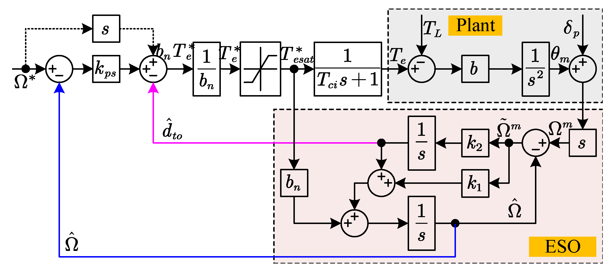
2.1. ESO-Based ADR Controller

2.1.1. Modelling of PMSM Mechanical Dynamics

Generating the optimal torque reference T e * for the inner torque control loop is the core to suppress the torque ripple of the PMSM speed regulation system. Hence, in order to deduce the torque reference, the equation of the PMSM motion system considering uncertainties of the moment of inertia can be modified as:
Ω ˙ = T e * T e * T e B Ω T L J = b T e * + d n = b n T e * + d t o
where Ω is the mechanical angular velocity, T e is the electromagnetic torque, J is the moment of inertial, B is the viscous friction torque coefficient, T L is the load torque, b = 1 / J is the control gain, and d n = T e * T e + B Ω + T L / J is the nominal disturbance with a given inertial. J n and b n = 1 / J n are nominal value of J and b, respectively, and d t o = b b n T e * + d n is the total disturbance.

2.1.2. Speed Controller Design

Define the reference mechanical angular velocity as Ω * , then the speed tracking error e s = Ω * Ω can be derived as
e ˙ s = Ω ˙ * Ω ˙ = Ω ˙ * b n T e * d t o
Applying the linear feedback control law,
e ˙ s = k p s e s
where k p s is the proportional gain.
Substituting (3) into (2), the control term can be rewritten as
T e * = Ω ˙ * + k p s Ω * Ω d t o b n
Generally, the mechanical angular velocity Ω and the total disturbance d t o in the Equation (4) can not be measured or calculated directly. Therefore, it is common to use their estimated values to substitute Ω and d t o . Then the torque reference can be revised as
T e * = Ω ˙ * + k p s Ω * Ω ^ d ^ t o b n
where Ω ^ and d ^ t o are the estimated mechanical angular velocity and total disturbance, respectively.
As the output of actual system is not infinite, the reference torque is usually limited as
T e * = T e max * s i g n T e * , | T e * | > T e max * T e * , | T e * | T e max *
where T e max * is the reference torque limit.
Ignoring the torque reference saturation, the system output mechanical angular velocity can be expressed by combining Equations (1) and (5)
Ω s = Ω * s + k p s s + k p s Ω ˜ s + 1 s + k p s d ˜ t o s
where Ω ˜ = Ω Ω ^ is the speed estimation error and d ˜ t o = d t o d ^ t o is the total disturbance estimation error.
It can be concluded from (7) that the performance of PMSM speed regulation system is determined by the proportional gain k p s , speed estimation deviation Ω ˜ and disturbance estimation deviation d ˜ t o . If the mechanical angular speed and total disturbance can be observed accurately, the system will have a good tracking performance and strong disturbance rejection ability.

2.1.3. Speed and Disturbance Observation

Usually, the actual rotor position θ m , which is further derived to obtain the mechanical angular velocity Ω , is measured by using the position sensors such as resolver and encoder. However, the commonly applied frequency method for speed calculation will result in measurement noise because of the quantization error in the position measurement. Hence, the measured mechanical position θ m m and speed Ω m are expressed as
θ m m = θ m + δ p Ω m = θ ˙ m m = Ω + δ n
where δ p ( s ) and δ n = s δ p ( s ) are the measurement noise of the position and speed, respectively.
In order to estimate the total disturbance contained in the Equation (5), a linear ESO is constructed as
Ω ˜ m = Ω m Ω ^ Ω ^ ˙ = b n T e * + k 1 Ω ˜ m + d ^ t o d ^ ˙ t o = k 2 Ω ˜ m
where Ω ˜ m is the error between measured speed and estimated speed, k 1 and k 2 are the observer gains.
With the block diagram of ADRC system and the conventional ESO illustrated as Figure 1 and Equation (1), the speed observation error and total disturbance can be derived as
Ω ˜ m s = s s 2 + k 1 s + k 2 s δ n s + d t o s d ^ t o s = k 2 s 2 + k 1 s + k 2 s δ n s + d t o s
From (10), it can be found that the speed estimation error is proportional to the derivative of the total disturbance. If accurate speed is required, the observed speed should not be applied to serve as the feedback component. Moreover, the observed system disturbance can be treated as the actual disturbance in the system filtered by a typical second-order low pass filter (LPF). Therefore, the low-frequency components of the total disturbance can be estimated accurately by the ESO. However, due to the influence of the cogging torque, varying parameters, non-linearity of the inverter, etc., the waveform of torque ripple contains certain high order harmonics, which are difficult to be estimated and rejected by the ESO. Hence, the performance of the PMSM speed regulation system cannot be guaranteed only with a conventional ADRC system.

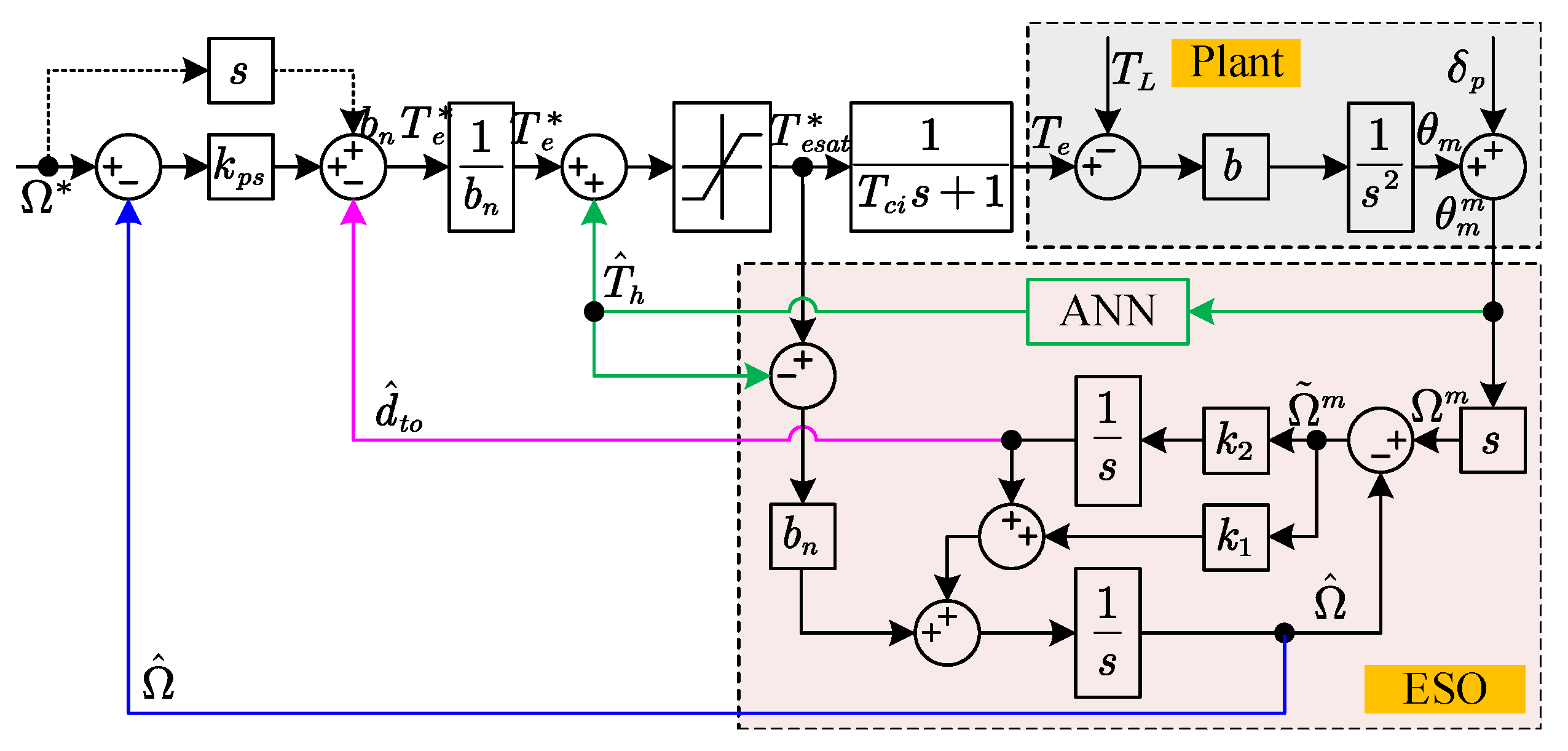
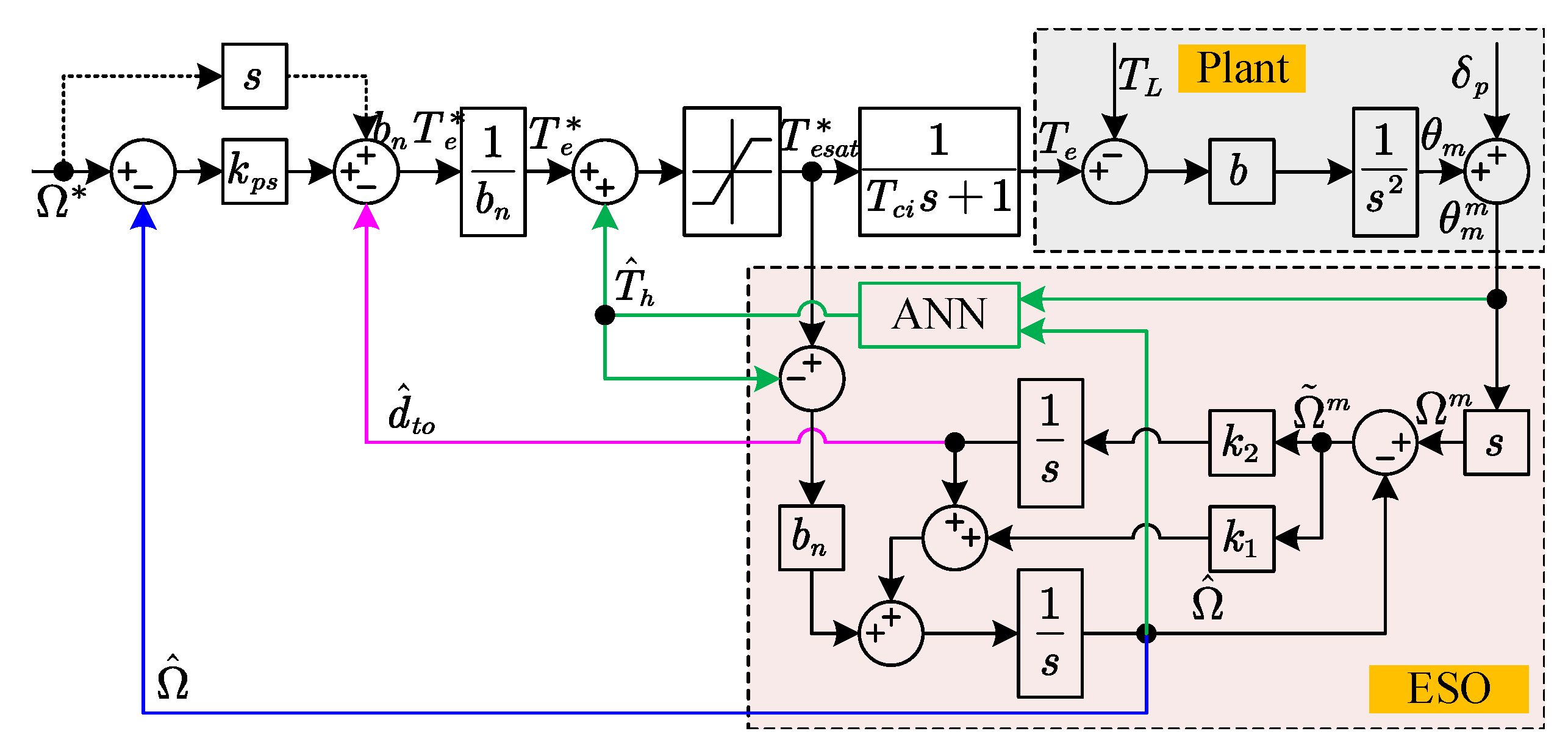
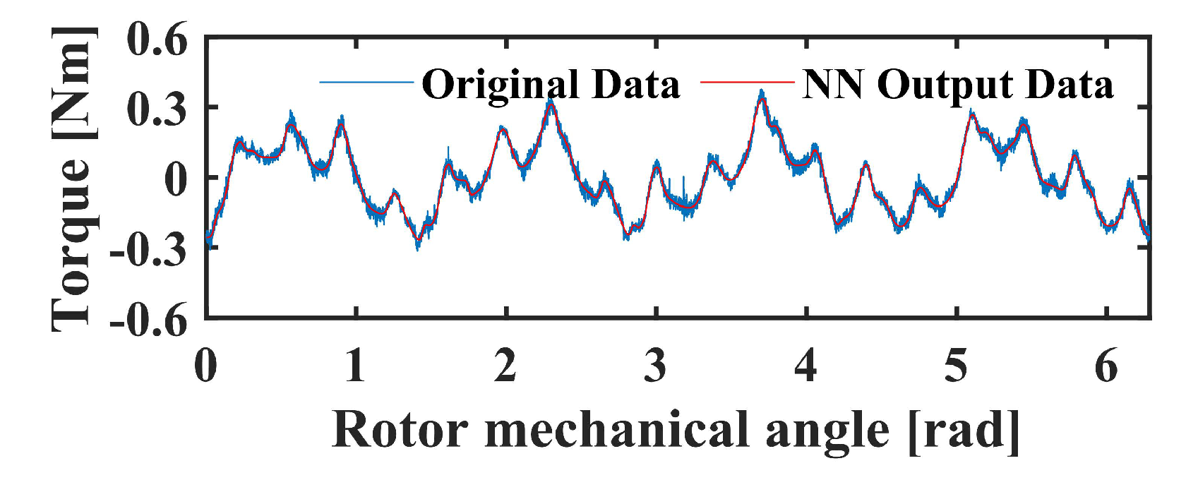
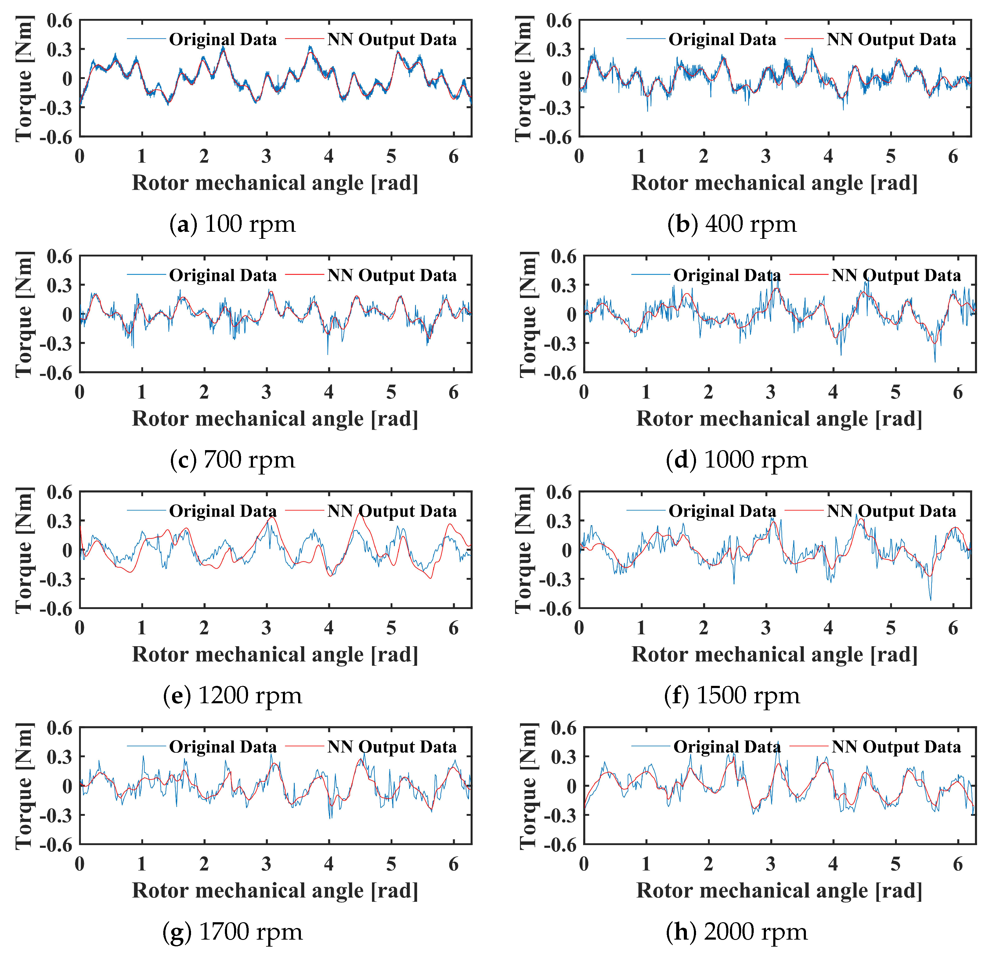
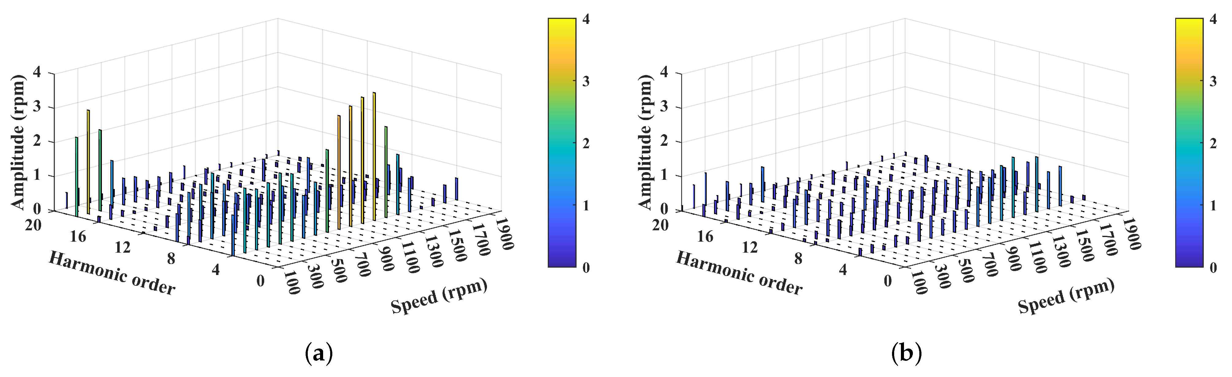
2.2. Torque Ripple Suppression Using Neural Network

Since only the low-frequency parts of the disturbance can be observed by ESO, the neural network compensator is designed and embedded in an ADRC frame to further minimize the high-frequency components contained in the torque ripple. In the literature about the torque model-based approaches [19,20,21,22,23,24,25] mentioned above, the torque ripple analytical model, including various sources of disturbance, has to be built, which is quite complex and it is challenging to cover all the sources of the torque ripple. Different from these schemes, the proposed neural network compensator is able to directly learn the waveform of the actual torque ripple and generate the torque compensation without the need of analyzing the harmonics in the system.
Therefore, considering the compensation effect of the neural network, Equation (5) including the high-frequency disturbance can be modified as
T e * = Ω ˙ * + k p s Ω * Ω ^ d ^ t o + b n T ^ h b n
where T ^ h is the output of the neural network.
Similarly, in order to avoid low-frequency disturbance estimation performance being affected by the output of the neural network, the expression of ESO in Equation (9) should be revised as
Ω ˜ m = Ω m Ω ^ Ω ^ ˙ = b n T e * T ^ h + k 1 Ω ˜ m + d ^ t o d ^ ˙ t o = k 2 Ω ˜ m
It is common to assume the torque ripple depend on the rotor position because the cogging torque and non-sinusoidal back-EMF are directly related to the rotor mechanical angle. Hence, the neural network using the rotor position as the single input and outputting the torque compensation is embedded in the ADRC system, as Figure 2 illustrates.
However, there are some unmodeled and unpredictable disturbances existing in the PMSM speed regulation system during machine operation, such as temperature issues, magnetic saturation, friction torque, etc., which may also cause severe torque ripples. Hence, another neural network adopting both the rotor position and the speed as inputs to generate the torque compensation is proposed as Figure 3. In this way, there are more features to facilitate the neural network to deal with various disturbances.

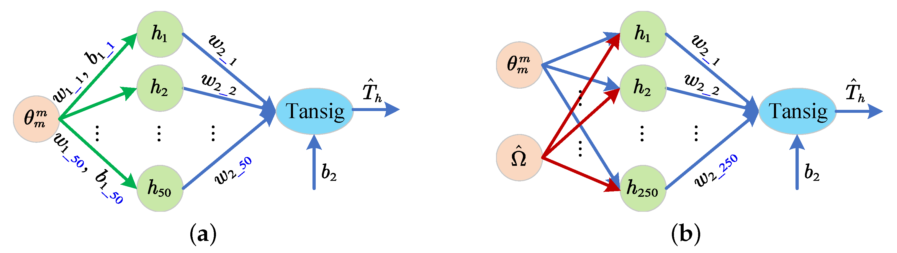
2.2.1. Structure of the Neural Network

In the Figure 4, the structures of two-layer neural networks with single input and double inputs are illustrated, respectively. Since the double inputs neural network requires more data to fit the target data compared with single input, it adopts 250 nodes in the hidden layer to guarantee the accuracy, while the neural network with single input only adopts 50 nodes. Moreover, they both use the tansig function as the activation function in the hidden layer, which is expressed as
h = tansig x w 1 + b 1
where h = h 1 · · · h 50 or h = h 1 · · · h 250 is the output vector of the hidden layer, x = θ m m or x = θ m m Ω ^ is the neural network input, ω 1 = w 1 _ 1 · · · w 1 _ 50 or ω 1 = w 1 _ 1 1 · · · w 1 _ 250 1 w 1 _ 1 2 · · · w 1 _ 250 2 is the weight vector between input layer and hidden layer, and b 1 = b 1 _ 1 · · · b 1 _ 50 or b 1 = b 1 _ 1 · · · b 1 _ 250 is the bias vector of the hidden layer for the neural network with single input and double inputs, respectively.
Similar to the hidden layer, the output layer adopting the tansig function as the activation function can be expressed as
T ^ h = tansig hw 2 T + b 2
where w 2 = w 2 _ 1 · · · w 2 _ 50 or w 2 = w 2 _ 1 · · · w 2 _ 250 is the weight factor vector between the hidden layer and output layer of the neural network with single input and double inputs, respectively, and b 2 is the bias of the output layer.
It can be seen that there are lots of parameters of the neural network to be determined. For the purpose of generating the extra current harmonics to accurately compensate the torque ripple, suitable training method should be applied to regulate the parameters.

2.2.2. Training Algorithm of Neural Network

In order to train the neural network, the inputs and desired results, i.e., the rotor position, speed, and their corresponding actual torque ripple, should be measured at the same time. If the output of neural network is able to fit the torque ripple model accurately, the harmonics can be compensated and suppressed. Therefore, the gradient descent algorithm is adopted to train the neural network. Before applying it, the error between the target results and neural network output is defined as
e k = T h k T ^ h k
where e k is the fitting error at the kth iteration, T h k and T ^ h k are the actual torque ripple and neural network output at at the kth iteration, respectively.
Then the cost function J is defined as
J k = 1 2 e k 2 = 1 2 T h k T ^ h k 2
In the gradient descent algorithm, the fitting error in the neural network is back-propagated to minimize the cost function. Therefore, the gradient of J to w 2 and b 2 can be calculated as
J w 2 k 1 = ( T h k T ^ h k ) h k 1 T ^ h k 2 = e k h k 1 T ^ h k 2
J b 2 k 1 = T h k T ^ h k 1 T ^ h k 2 = e k 1 T ^ h k 2
Based on the calculation results of the gradient, the weights and bias between the hidden layer and output layer are updated as
w 2 k = w 2 k 1 + η e k h k 1 T ^ h k 2
b 2 k = b 2 k 1 + η e k 1 T ^ h k 2
where η is the learning rate.
In order to calculate the gradient of the cost function to the parameters between input and hidden layer, the chain rule is applied. Therefore, based on Equations (17) and (18), the gradients of J to w 1 and b 1 are derived as
J w 1 k 1 = e k 1 T ^ h k 2 w 2 k 1 1 h k 2 x k
J b 1 k 1 = e k 1 T ^ h k 2 b 1 k 1 1 h k 2
Hence, based on their gradients, w 1 and b 1 are updated as
w 1 k = w 1 k 1 + η e k 1 T ^ h k 2 w 2 k 1 1 h k 2 x k
b 1 k = w 1 k 1 + η e k 1 T ^ h k 2 w 2 k 1 1 h k 2
These parameters of neural network will keep updating until the error between the actual torque ripple and neural network output becomes small enough or the number of iterations reaches the preset value. During the training process, the value of η should be selected carefully. On the one hand, if it is set very small, the training process will cost quite a significant amount of time due to slow iteration speed; on the other hand, if the learning rate is very large, the neural network may miss the optimal value and cause the system to become unstable.

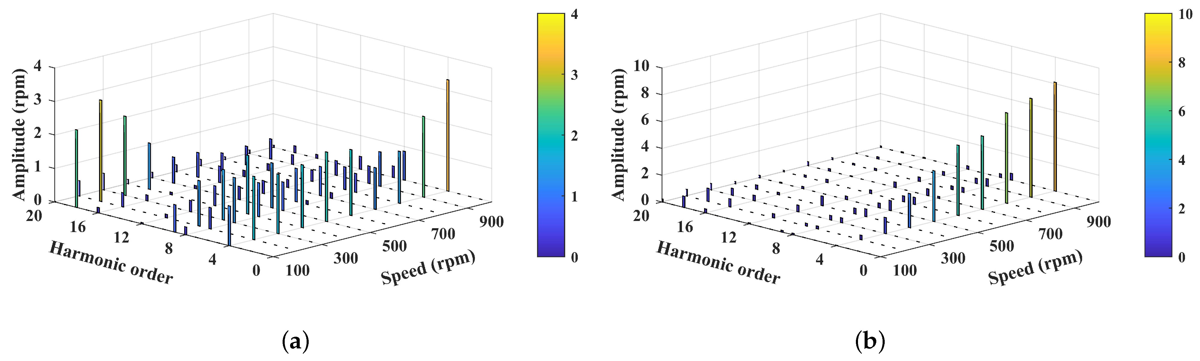
3. Results and Discussion

In this section, experiments are conducted to verify the effectiveness of the proposed NN-ESO-ADRC controller and the theoretical analysis. A comprehensive comparison is made between the conventional ADRC system and the proposed NN-ESO-ADRC controller with single input and double inputs.

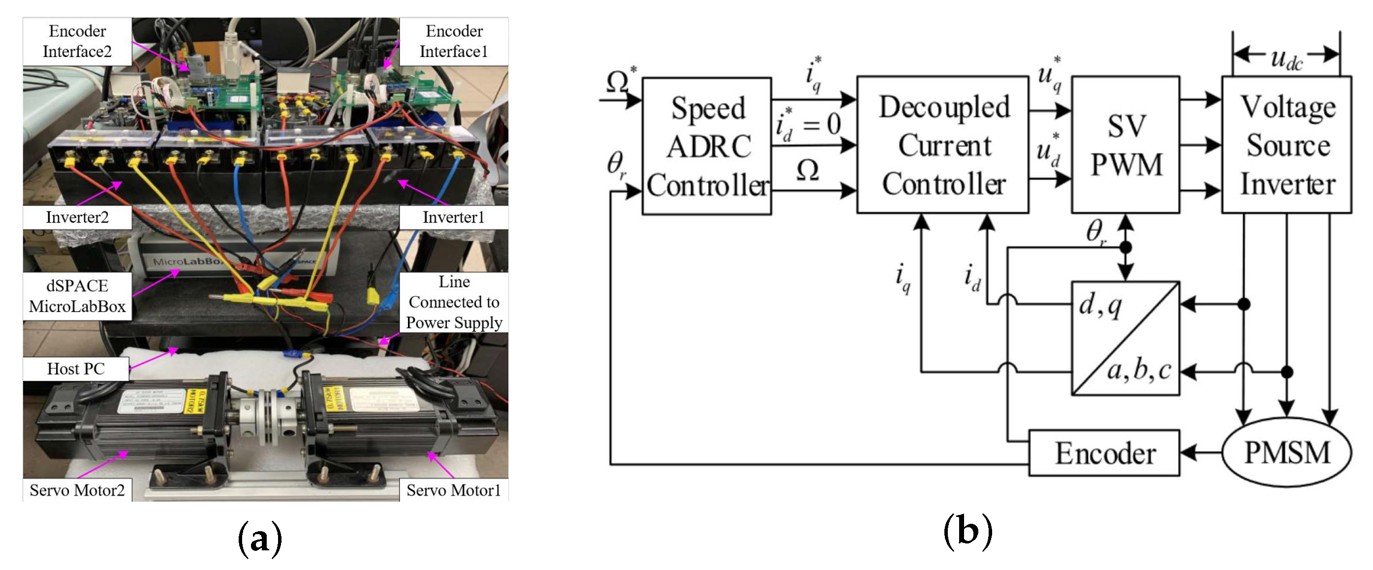
3.1. Test Bench Setup

Table 1 indicates the specification of the PMSM under evaluation, and Figure 5a illustrates the configuration of the test bench. These two PMSMs are driven by two separate inverters with a common DC bus, which include an intelligent power module (IPM) and hall sensors to measure the current and voltage. The dSPACE MicroLabBox is employed to implement the control algorithm. As presented in Figure 5b, the i d * = 0 control strategy is adopted with the space vector pulse width modulation (SVPWM) technique. i d and i q are regulated by the decoupled current controller in the current control loop. In addition, the rotor mechanical angle is measured by the incremental encoder with 2500 pulses per revolution. A programmable DC power source is set as 150 V to provide the DC bus voltage. In addition, the control frequency and sampling rate are set the same as 10 kHz.

3.2. Experimental Verification

Since the torque ripple can directly result in speed ripple, the feedback speed signal are measured to help evaluate the torque ripple suppression performance of the proposed NN-ESO-ADRC system. Employing the same test approach mentioned in [31], the generalized integrator extended state observer (GIESO) is applied to estimate and model the torque ripple. When the speed harmonics are fully suppressed by GIESO, the estimated disturbance torque can be treated as torque ripple. In addition, the speed is regulated with k p s = 200 rad/s and the natural frequency of the ESO is chosen as 500 rad/s.

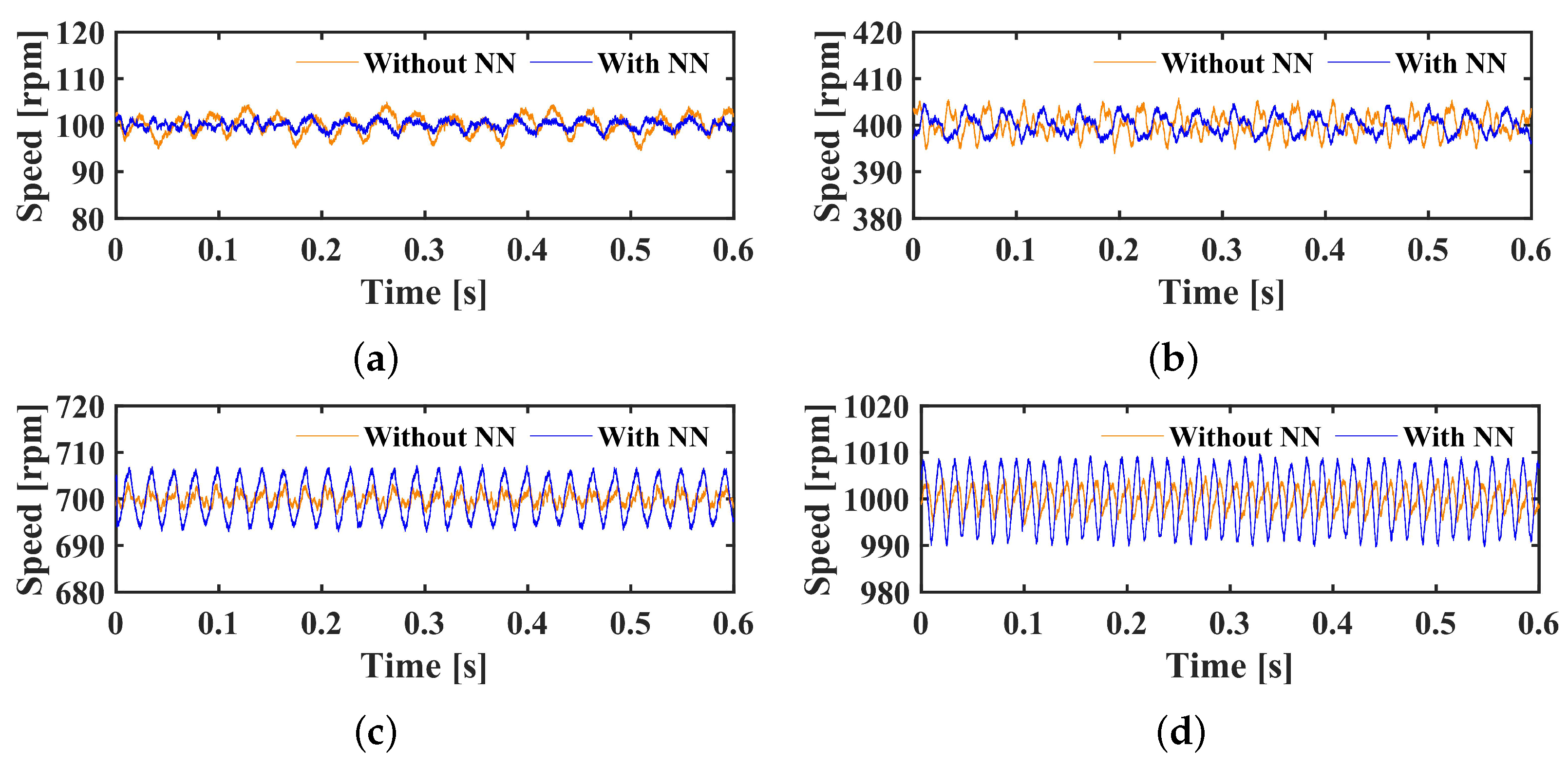
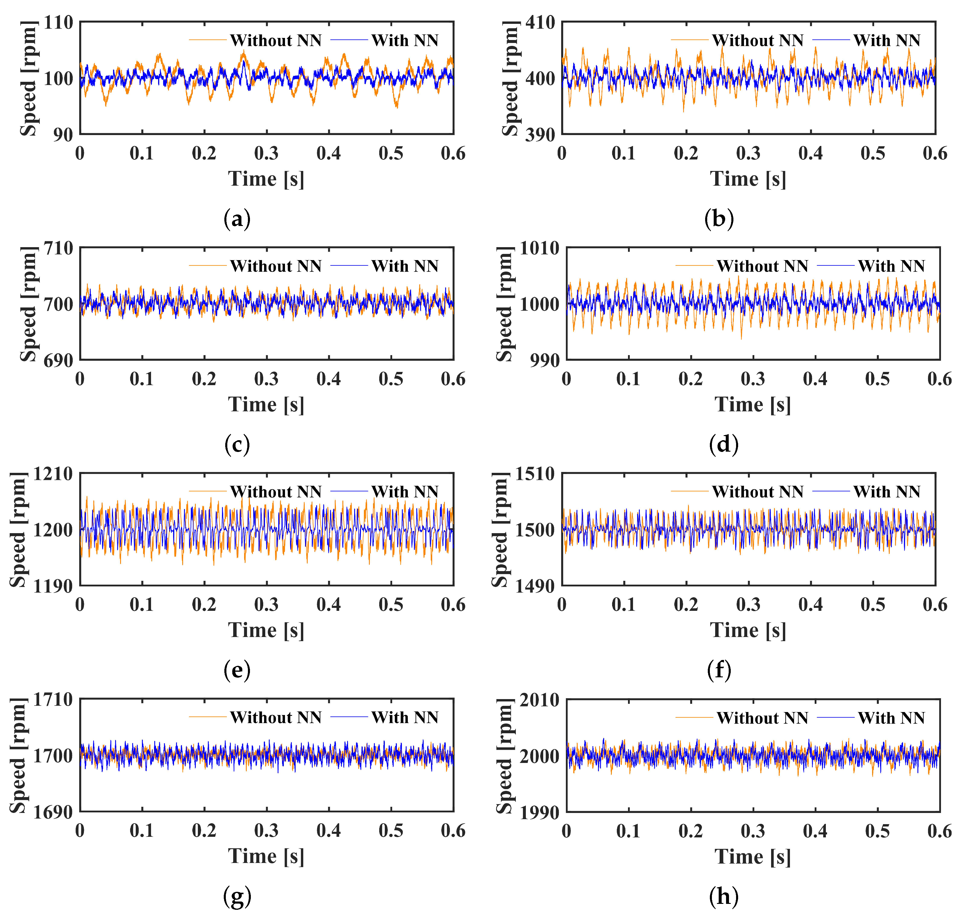
3.2.1. Performance of the NN-ESO-ADRC with Single Input

It is commonly assumed that the torque ripple depend on the rotor position; therefore, the performance of NN-ESO-ADRC with the rotor mechanical angle as the input is first analyzed. In Figure 6, the actual torque ripple of the prototype at the speed of 60 rpm is shown as the blue waveform, while the training result of the neural network is illustrated as the red waveform. It can be seen that the neural network output can fit the actual torque ripple very well. Moreover, the training process is quite fast in the experiment. The first reason is that the neural network only has one hidden layer with 50 nodes, which can reduce the training time. In addition, the ESO can estimate the low-frequency disturbance, which helps reduce the harmonics contained in the torque ripple, so that the complexity of the training data is simplified.
Under different speed references from 100 rpm to 1000 rpm, with an interval of 100 rpm, the torque ripple suppression performance of the conventional ESO-ADRC and NN-ESO-ADRC are illustrated in Figure 7. In these 3D analysis graphics of the speed, the magnitude of various orders of speed harmonics at different speed references are illustrated. Compared with the conventional ESO-ADRC, it can be seen that most of the harmonics contained in the torque ripple are minimized by the NN-ESO-ADRC. Within the relatively low speed range, i.e., 100 rpm to 400 rpm, the harmonics are effectively suppressed by the neural network compensator, especially the higher order of the harmonics, which is consistent with previous analysis. As the speed increases to high speed range, the magnitude of the low order harmonics become much larger in the ESO-ADRC system, which can be explained as the fundamental frequency increases with the speed, so that the frequency of the lower order of harmonics become larger than the low speed. Under this condition, the neural network is expected to suppress these harmonics. However, the magnitude of the harmonics become even more significant than the conventional ESO-ADRC. Although the high-frequency components are almost removed, the severe low order of harmonics will deteriorate the torque ripple suppression performance when the speed is increased.
To be specific, the waveforms of the speed response at different speed with and without the neural network are illustrated in Figure 8. At the speed of 100 rpm and 400 rpm, the speed ripple is reduced by the neural network compensator, and it is obvious that the high-frequency component in the speed signal is suppressed. However, when the speed is raised to 700 rpm, the speed ripple is instead increased in the NN-ESO-ADRC system. This phenomenon is more severe at the speed of 1000 rpm. From these results, it can be concluded that the torque ripple model varies under different speed. In other words, the torque ripple do not only depend on the rotor position, it is also influenced by the unconsidered or unmodeled disturbances in the PMSM system. As the target results of the training process of the neural network is measured at the speed of 60rpm, the actual torque ripple waveform may vary little for the operation speed close to 60rpm. Therefore, the neural network compensator can effectively suppress the torque ripple in a low-speed range. When the speed increases, the actual torque ripple model become quite different from the training target, which deteriorates the performance of ADRC system. Hence, the torque ripple suppression ability of the neural network with only rotor position as input is limited.

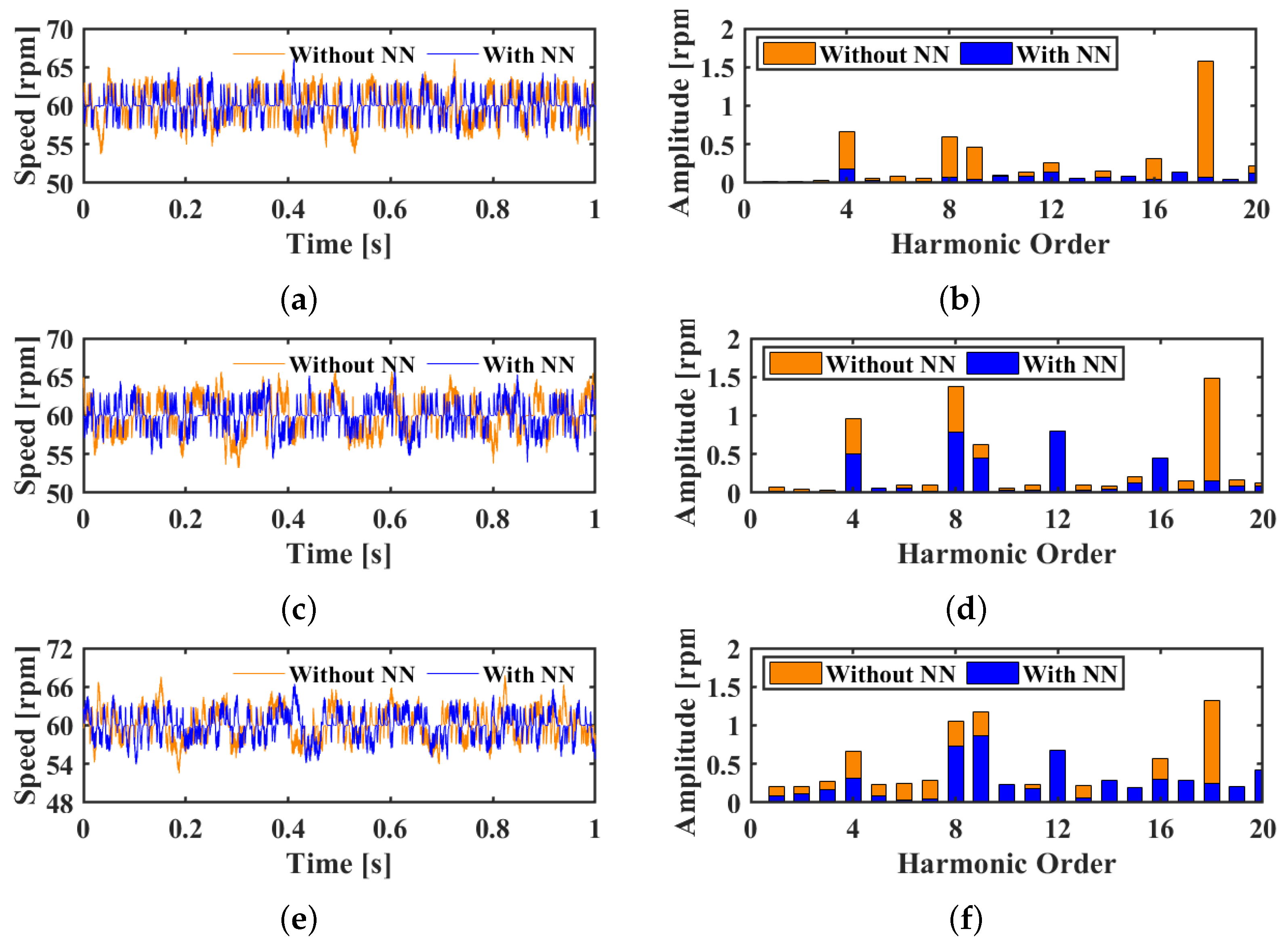
3.2.2. Performance of the NN-ESO-ADRC with Double Inputs

Since the torque ripple model varies with the speed, the estimated mechanical angular velocity of the ESO is used as another input of the neural network to improve the compensation accuracy. With this double inputs neural network, the actual torque ripple should be measured at various speeds. Before applying the training method, the measured torque ripples are presented as the blue waveform in the Figure 9. Additionally, with the gradient descent algorithm, the training results are illustrated as a red waveform in these figures. It can be found that the actual torque ripple waveform relative to the rotor position are quite different at various speeds, which verifies the deduction that the torque ripples do not only depend on the rotor position. In addition, the fitting performance of the neural network is overall satisfied, but, at the high-speed range, it is not as good as the low-speed range, which might weaken the compensation effectiveness during PMSM high-speed operation.
In order to evaluate the performance of the NN-ESO-ADRC with double inputs, the spectrum analysis of the conventional ESO-ADRC system and the modified NN-ESO-ADRC are compared in Figure 10, with the maximum test speed expanded from 1000 rpm to 2000 rpm. It can be observed obviously that the amplitude of almost all the harmonics at each speed are reduced a lot by the modified neural network compensator. In the low-speed range (smaller than 700 rpm), both the low order and high order of the harmonics are suppressed significantly by the NN-ESO-ADRC. In addition, the low order of the harmonics within medium speed range (700 rpm–1500 rpm) in the conventional ADRC system have quite large amplitude, which are also reduced by the neural network. However, for the speed at high-speed range (1500 rpm–2000 rpm), the suppression effect of the neural network compensator is not very significant.
The comparison of the speed ripple with and without neural network at various speed are presented in Figure 11. Among the figures of relatively low speed, it can be observed that the speed ripple with the neural network is much smaller than it in the conventional ESO-ADRC system. This is because the neural network output fit the actual torque ripples accurately, especially at a speed smaller than 400 rpm. Therefore, the generated optimal current harmonics can suppress the torque ripple effectively. For the medium-speed range, such as 1200 rpm and 1500 rpm, the fitting performance is not as good as the low speed conditions. From Figure 9, it can be seen that the neural network can only fit the relatively low order harmonics of the torque ripple, while there are certain high-frequency harmonics left in the total disturbance. Therefore, the effect of speed ripple minimization at medium-speed range is not very strong. For the high-speed range, there is no significant speed ripple difference between the ESO-ADRC and the modified NN-ESO-ADRC. There are two reasons to explain this phenomenon. On the one hand, the training result of the neural network cannot fit the actual torque ripple very well; on the other hand, as the PMSM system can be treated as a low pass filter, high order of the harmonics of the speed ripple are filtered out, especially at high speed, even without the neural network, there are not many harmonics in the speed signal.
For the speed higher than 1000 rpm, the torque ripple suppression effectiveness of the neural network becomes weaker because the fitting performance is not as good as the low-speed conditions. One of the possible reasons is the sampling rate limitation. At low speed, the variation of both the rotor position value and torque ripple value is slow, so there are plenty of data for the neural network to learn the complex torque ripple model thoroughly. However, as the speed increases, the rotor position varies significantly between two sampling instant, which means some of the necessary input data and target data are ignored. Hence, the performance of torque ripple suppression is not significant at very high speed.
Since the above experiments under various speeds are conducted under no load condition, it is also necessary to evaluate the torque ripple suppression performance of the proposed method against the load torque variation. Therefore, different load torque including 0.1Nm, 1.1Nm, and 2.2Nm are applied at the speed of 60rpm, and the results are illustrated in Figure 12. It can be observed that the NN-ESO-ADRC system can reduce various orders of the speed harmonics effectively with extremely small load torque from Figure 12b. However, with the load torque of 1.1Nm, large disturbances are induced in both conventional ESO-ADRC system and NN-ESO-ADRC system. This phenomenon is deteriorated when the load torque is raised to 2.2Nm. Although the neural network can still reduce several orders of the harmonics, such as 4th, 8th, and 18th, its compensation effect is not as significant as no load condition. Moreover, the NN compensator may even introduce extra disturbances to the conventional ADRC system. Hence, it can be concluded that the current distort the original torque ripple waveform with the increased load torque. To be specific, ref. [32] reveals that the magnitude of cogging torque are larger under loading condition because the load torque induces extra flux leakage through tooth tips and higher saturation level. For the similar reason, the waveform of back-EMF contains more and larger harmonics and, in turn, causes severe torque ripple.

4. Conclusions

In this paper, an NN-ESO-ADRC system is proposed to regulate the speed and suppress the torque ripple. Different from the commonly used speed-based methods or torque ripple model-based methods, a two-layer neural network compensator is embedded in the conventional ADRC system to generate extra current harmonics. It is found that the torque ripple do not only depend on the rotor position, therefore, both the rotor position and the mechanical angular velocity are used as inputs of the neural network. By fitting the actual torque ripple, there is no need to build the analytical model of the cogging torque, flux linkage, inverter non-linearity, and other unmodeled disturbances in the system. As the structure of the neural network is simple, both the computation time and computer memory can be saved. Experiment results verify the effectiveness of the proposed method. The neural network compensator with double inputs can suppress the harmonics contained in the torque ripple at various machine operation speeds.
In future work, since it has been proved that the load torque induces an extra torque ripple, the current will be used as the third input of the neural network to further improve the torque ripple suppression performance. In addition, the update law of the neural network weights can be improved to enhance the adaptability to various disturbances and simplify the neural network training process.

Author Contributions

Conceptualization, C.Z., Y.Z. and C.H.T.L.; methodology, C.Z. and Y.Z.; software, C.Z. and Y.Z.; validation, C.Z., H.W. and Q.H.; formal analysis, C.Z. and Y.Z.; investigation, C.Z., H.W. and Q.H.; writing—original draft preparation, C.Z. and Y.Z.; writing—review and editing, C.Z., Y.Z., H.W., Q.H. and C.H.T.L.; supervision, C.H.T.L.; funding acquisition, C.H.T.L. All authors have read and agreed to the published version of the manuscript.

Funding

This research is supported by the Agency for Science, Technology and Research (A*STAR) under its IAF-ICP Programme ICP1900093 and the Schaeffler Hub for Advanced Research at NTU.

Data Availability Statement

Not applicable.

Conflicts of Interest

The authors declare no conflict of interest.

References

  1. Cai, S.; Kirtley, J.L.; Lee, C.H.T. Critical Review of Direct-Drive Electrical Machine Systems for Electric and Hybrid Electric Vehicles. IEEE Trans. Energy Convers. 2022, 37, 2657–2668. [Google Scholar] [CrossRef]
  2. Zhu, C.; Zeng, Z.; Zhao, R. Comprehensive Analysis and Reduction of Torque Ripples in Three-Phase Four-Switch Inverter-Fed PMSM Drives Using Space Vector Pulse-Width Modulation. IEEE Trans. Power Electron. 2017, 32, 5411–5424. [Google Scholar] [CrossRef]
  3. Holtz, J.; Springob, L. Identification and Compensation of Torque Ripple in High-Precision Permanent Magnet Motor Drives. IEEE Trans. Ind. Electron. 1996, 43, 309–320. [Google Scholar] [CrossRef] [Green Version]
  4. Houari, A.; Bouabdallah, A.; Djerioui, A.; Machmoum, M.; Auger, F.; Darkawi, A.; Olivier, J.-C.; Benkhoris, M.F. An Effective Compensation Technique for Speed Smoothness at Low-Speed Operation of PMSM Drives. IEEE Trans. Ind. Appli. 2018, 54, 647–655. [Google Scholar] [CrossRef]
  5. Abosh, A.H.; Zhu, Z.Q.; Ren, Y. Reduction of Torque and Flux Ripples in Space Vector Modulation-Based Direct Torque Control of Asymmetric Permanent Magnet Synchronous Machine. IEEE Trans. Power Electron. 2017, 32, 2976–2986. [Google Scholar] [CrossRef]
  6. Güemes, J.A.; Iraolagoitia, A.M.; Del Hoyo, J.I.; Fernández, P. Torque Analysis in Permanent-Magnet Synchronous Motors: A Comparative Study. IEEE Trans. Energy Convers. 2011, 26, 55–63. [Google Scholar] [CrossRef]
  7. Tian, B.; An, Q.-T.; Duan, J.-D.; Semenov, D.; Sun, D.-Y.; Sun, L. Cancellation of Torque Ripples With FOC Strategy Under Two-Phase Failures of the Five-Phase PM Motor. IEEE Trans. Power Electron. 2017, 32, 5459–5472. [Google Scholar] [CrossRef]
  8. Lai, C.; Feng, G.; Mukherjee, K.; Kar, N.C. Investigations of the Influence of PMSM Parameter Variations in Optimal Stator Current Design for Torque Ripple Minimization. IEEE Trans. Energy Convers. 2017, 32, 1052–1062. [Google Scholar] [CrossRef]
  9. Wang, L.; Zhu, Z.Q.; Bin, H.; Gong, L.M. Current Harmonics Suppression Strategy for PMSM With Nonsinusoidal Back-EMF Based on Adaptive Linear Neuron Method. IEEE Trans. Ind. Electron. 2020, 67, 9164–9173. [Google Scholar] [CrossRef]
  10. Nakao, N.; Akatsu, K. Suppressing Pulsating Torques: Torque Ripple Control for Synchronous Motors. IEEE Ind. Appl. Mag. 2014, 20, 33–44. [Google Scholar] [CrossRef]
  11. Evans, S.A. Salient Pole Shoe Shapes of Interior Permanent Magnet Synchronous Machines. In Proceedings of the XIX International Conference on Electrical Machines (ICEM 2010), Rome, Italy, 6–8 September 2010; pp. 1–6. [Google Scholar]
  12. Liu, J.; Li, H.; Deng, Y. Torque Ripple Minimization of PMSM Based on Robust ILC Via Adaptive Sliding Mode Control. IEEE Trans. Power Electron. 2018, 33, 3655–3671. [Google Scholar] [CrossRef]
  13. Sun, X.; Wu, J.; Lei, G.; Guo, Y.; Zhu, J. Torque Ripple Reduction of SRM Drive Using Improved Direct Torque Control with Sliding Mode Controller and Observer. IEEE Trans. Ind. Electron. 2021, 68, 9334–9345. [Google Scholar] [CrossRef]
  14. Zuo, Y.; Chen, J.; Zhu, X.; Lee, C.H.T. Different Active Disturbance Rejection Controllers Based on the Same Order GPI Observer. IEEE Trans. Ind. Electron. IEEE Trans. Ind. Electron. 2022, 69, 10969–10983. [Google Scholar] [CrossRef]
  15. Tang, M.; Gaeta, A.; Formentini, A.; Zanchetta, P. A Fractional Delay Variable Frequency Repetitive Control for Torque Ripple Reduction in PMSMs. IEEE Trans. Ind. Electron. IEEE Trans. Ind. Appl. 2017, 53, 5553–5562. [Google Scholar] [CrossRef] [Green Version]
  16. Tang, M.; Formentini, A.; Odhano, S.A.; Zanchetta, P. Torque Ripple Reduction of PMSMs Using a Novel Angle-Based Repetitive Observer. IEEE Trans. Ind. Electron. 2020, 67, 2689–2699. [Google Scholar] [CrossRef] [Green Version]
  17. Qu, J.; Zhang, P.; Jatskevich, J.; Zhang, C. Torque Ripple Reduction of Permanent Magnet Synchronous Machine Drives Based on Novel Speed Harmonic Control at Low-Speed Operation. IEEE Trans. Ind. Electron. 2022, 70, 7683–7694. [Google Scholar] [CrossRef]
  18. Feng, G.; Lai, C.; Kar, N.C. A Closed-Loop Fuzzy-Logic-Based Current Controller for PMSM Torque Ripple Minimization Using the Magnitude of Speed Harmonic as the Feedback Control Signal. IEEE Trans. Ind. Electron. 2017, 64, 2642–2653. [Google Scholar] [CrossRef]
  19. Qu, J.; Jatskevich, J.; Zhang, C.; Zhang, S. Torque Ripple Reduction Method for Permanent Magnet Synchronous Machine Drives With Novel Harmonic Current Control. IEEE Trans. Energy Convers. 2021, 36, 2502–2513. [Google Scholar] [CrossRef]
  20. Lai, C.; Feng, G.; Mukherjee, K.; Loukanov, V.; Kar, N.C. Torque Ripple Modeling and Minimization for Interior PMSM Considering Magnetic Saturation. IEEE Trans. Power Electron. 2018, 33, 2417–2429. [Google Scholar] [CrossRef]
  21. Feng, G.; Lai, C.; Tan, X.; Wang, B.; Kar, N.C. Optimal Current Modeling and Identification for Fast and Efficient Torque Ripple Minimization of PMSM Using Theoretical and Experimental Models. IEEE Trans. Ind. Electron. 2021, 68, 11806–11816. [Google Scholar] [CrossRef]
  22. Truong, P.H.; Flieller, D.; Nguyen, N.K.; Mercklé, J.; Sturtzer, G. Torque Ripple Minimization in Non-Sinusoidal Synchronous Reluctance Motors Based on Artificial Neural Networks. Electr. Power Syst. Res. 2016, 140, 37–45. [Google Scholar] [CrossRef] [Green Version]
  23. Flieller, D.; Nguyen, N.K.; Wira, P.; Sturtzer, G.; Abdeslam, D.O.; Merckle, J. A Self-Learning Solution for Torque Ripple Reduction for Nonsinusoidal Permanent-Magnet Motor Drives Based on Artificial Neural Networks. IEEE Trans. Ind. Electron. 2014, 61, 655–666. [Google Scholar] [CrossRef] [Green Version]
  24. Mattavelli, P.; Tubiana, L.; Zigliotto, M. Torque-Ripple Reduction in PM Synchronous Motor Drives Using Repetitive Current Control. IEEE Trans. Power Electron. 2005, 20, 1423–1431. [Google Scholar] [CrossRef]
  25. Cho, H.-J.; Kwon, Y.-C.; Sul, S.-K. Torque Ripple-Minimizing Control of IPMSM With Optimized Current Trajectory. IEEE Trans. Ind. Appl. 2021, 57, 3852–3862. [Google Scholar] [CrossRef]
  26. Moustafa, E.B.; Elsheikh, A. Predicting Characteristics of Dissimilar Laser Welded Polymeric Joints Using a Multi-Layer Perceptrons Model Coupled with Archimedes Optimizer. Polymers 2023, 15, 233. [Google Scholar] [CrossRef] [PubMed]
  27. Elsheikh, A.H. Applications of Machine Learning in Friction Stir Welding: Prediction of Joint Properties, Real-Time Control and Tool Failure Diagnosis. Eng. Appl. Artif. Intell. 2023, 121, 105961. [Google Scholar] [CrossRef]
  28. Elsheikh, A.H.; El-Said, E.M.S.; Abd Elaziz, M.; Fujii, M.; El-Tahan, H.R. Water Distillation Tower: Experimental Investigation, Economic Assessment, and Performance Prediction Using Optimized Machine-Learning Model. J. Clean. Prod. 2023, 388, 135896. [Google Scholar] [CrossRef]
  29. Khoshaim, A.B.; Moustafa, E.B.; Bafakeeh, O.T.; Elsheikh, A.H. An Optimized Multilayer Perceptrons Model Using Grey Wolf Optimizer to Predict Mechanical and Microstructural Properties of Friction Stir Processed Aluminum Alloy Reinforced by Nanoparticles. Coatings 2021, 11, 1476. [Google Scholar] [CrossRef]
  30. Elsheikh, A. Bistable Morphing Composites for Energy-Harvesting Applications. Polymers 2022, 14, 1893. [Google Scholar] [CrossRef]
  31. Zuo, Y.; Zhu, J.; Jiang, W.; Xie, S.; Zhu, X.; Chen, W.-H.; Lee, C.H.T. Active Disturbance Rejection Controller for Smooth Speed Control of Electric Drives Using Adaptive Generalized Integrator Extended State Observer. IEEE Trans. Power Electron. 2023, 38, 4323–4334. [Google Scholar] [CrossRef]
  32. Azar, Z.; Zhu, Z.Q.; Ombach, G. Influence of Electric Loading and Magnetic Saturation on Cogging Torque, Back-EMF and Torque Ripple of PM Machines. IEEE Trans. Magn. 2012, 48, 2650–2658. [Google Scholar] [CrossRef]
Figure 1. Block diagram of the conventional ESO-ADRC system.
Wevj 14 00092 g001
Figure 2. Block diagram of the NN-ESO-ADRC system with single input.
Wevj 14 00092 g002
Figure 3. Block diagram of the NN-ESO-ADRC with double inputs.
Wevj 14 00092 g003
Figure 4. Neural network structure: (a) single input with 50 nodes in the hidden layer and (b) double inputs with 250 nodes in the hidden layer.
Wevj 14 00092 g004
Figure 5. Test bench: (a) configuration and (b) block diagram.
Wevj 14 00092 g005
Figure 6. The actual torque ripple waveform and output of the trained NN at the speed of 60 rpm.
Wevj 14 00092 g006
Figure 7. Spectrum analysis of the speed ripple: (a) in the conventional ESO-ADRC system and (b) in the NN-ESO-ADRC system with single input.
Wevj 14 00092 g007
Figure 8. Speed ripple in conventional ESO-ADRC system and NN-ESO-ADRC system at the speed of: (a) 100 rpm, (b) 400 rpm, (c) 700 rpm, and (d) 1000 rpm.
Wevj 14 00092 g008
Figure 9. The actual torque ripple waveform and output of the trained NN at the speed of: (a) 100 rpm, (b) 400 rpm, (c) 700 rpm, (d) 1000 rpm, (e) 1200 rpm, (f) 1500 rpm, (g) 1700 rpm, and (h) 2000 rpm.
Wevj 14 00092 g009
Figure 10. Spectrum analysis of the speed ripple: (a) in the conventional ESO-ADRC system and (b) in the modified NN-ESO-ADRC system with double inputs.
Wevj 14 00092 g010
Figure 11. Speed ripple in conventional ESO-ADRC system and modified NN-ESO-ADRC system at the speed of: (a) 100 rpm, (b) 400 rpm, (c) 700 rpm, (d) 1000 rpm, (e) 1200 rpm, (f) 1500 rpm, (g) 1700 rpm, and (h) 2000 rpm.
Wevj 14 00092 g011
Figure 12. Speed ripple in conventional ESO-ADRC system and modified NN-ESO-ADRC system at the speed of 60 rpm. (a) 0.1 Nm load torque, (b) spectrum analysis with 0.1 Nm load torque, (c) 1.1 Nm load torque, (d) spectrum analysis with 1.1 Nm load torque, (e) 2.2 Nm load torque, and (f) spectrum analysis with 2.2 Nm load torque.
Wevj 14 00092 g012
Table 1. Parameters of the tested SPMSM.
SymbolQuantitySymbolQuantity
Rated power P N 0.75 (kW)PolePair numbers p n 4
Rated voltage U N 220 (V)D axis inductance L d 5.7 (mH)
Rated speed n N 3000 (rpm)Q axis inductance L q 5.7 (mH)
Rated torque T N 2.4 (Nm)Torque constant K t 0.553 (Nm/A)
Current limit I s m a x 9 (A)Motor inertia J1.62 × 10 4 ( kgm 2 )
Stator resistance R s 1.1 (Ohm)Motor system inertia T C 4.44 × 10 4 ( kgm 2 )
Disclaimer/Publisher’s Note: The statements, opinions and data contained in all publications are solely those of the individual author(s) and contributor(s) and not of MDPI and/or the editor(s). MDPI and/or the editor(s) disclaim responsibility for any injury to people or property resulting from any ideas, methods, instructions or products referred to in the content.

