Article

Bi-Directional Cuk Equalizer-Based Li-Ion Battery Pack Equalization Control Strategy Research

Department of Electrical Engineering, Chongqing Three Gorges University, Chongqing 404100, China
*
Author to whom correspondence should be addressed.
World Electr. Veh. J. 2023, 14(4), 86; https://doi.org/10.3390/wevj14040086
Submission received: 1 March 2023 / Revised: 23 March 2023 / Accepted: 24 March 2023 / Published: 28 March 2023

Abstract

:
For the secure usage of battery charging and discharging within electric vehicles, the study of cell pack equalization technology is essential. Therefore, in this paper, an improved Bidirectional Cuk equalizer (BCEQ) structure based on a variable-domain fuzzy PID (VFPID) control equalization strategy is recommended in stages. With the new equalization topology, only half of the capacitive and inductive components are needed to transfer energy between any two individual cells in the power supply. In addition, the proposed VFPID control strategy further improves the efficiency of the equalization model by dynamically adjusting the magnitude of the equalization current parameters. Through simulation experiments, the improved topology was capable of substantially lessening the equalization time and increasing energy utilization by more than 4%. In comparison with the fuzzy PID (FPID) algorithm, around 27.3% faster equalization times can be achieved with the VFPID algorithm; the VFPID algorithm also performed well under the Dynamic Stress Test (DST) condition, demonstrating that the topology and equalization strategy suggested in this paper can successfully address the inconsistency of the FPID algorithm. It has been revealed that the topology and equalization methodology offered in this paper is effective in solving the battery pack inconsistency.

1. Introduction

Green energy vehicles will be crucial to the future development of the automobile industry because of the issues with environmental pollution brought on by the usage of conventional internal combustion engines and the current limitation of global oil resources [1]. An essential component of electric vehicles is the lithium-ion battery, which is fabricated from hundreds of batteries linked together by a series connection; due to the limitations of the production process, the single battery will be inconsistent [2] in the process of use. Due to the use of the environment and its capacity differences, the overcharge and overdischarge can very easily cause an explosion, endangering life and property safety. The emergence of equalization technology has greatly solved this problem [3].
The equalization topology circuit and equalization strategy are the two parts that constitute battery equalization technology. Active equalization and passive equalization are two different types of equalization, and their division is based on the way of power transmission [4]. Now, research is mainly focused on active equalization, which is a nondissipative equalization technique that dominantly utilizes capacitors and inductors to transmit power between single cells. Circuit equalization topologies can be classified into inductive, capacitive, transformer, and DC–DC converter types, concerning the various energy storage internal parts [5,6,7].
Energy transmission from a high-energy cell to a low-energy cell is managed to be maintained by a Buck–Boost converter that uses a reconfigurable architecture [8]; however, its circuit control is more complex. For this reason, a simple capacitor equalization topology has been proposed [9], where a common switch is connected in parallel with a capacitor, which effectively reduces the circuit size, but the added capacitance increases the circuit voltage uncertainty. The inductive type circuit has a larger equalization current than the switched-capacitor equalization topology. A single capacitive, inductive topology circuit has a smaller equalization current, resulting in a slower equalization speed, more commonly seen in DC–DC converter structures with high gain [10]. A bidirectional L2C3 resonant converter is introduced in [11], which can perform bidirectional constant current balancing and simplify the synchronous rectification process. A DC–DC converter equalization topology can provide active equalization of multiple batteries [12], potentially boost the capacity of the power bank, and achieve energy transfer, including any single battery with higher reliability. A resonant converter-based active equalization circuit [13] effectively reduces the equalization time, but the integration of its circuit needs to be improved. A capacitor threshold shifted Cuk converter and a decreased cell selector switch are used to have such an equalization for intercell voltage [14]; using a low-frequency selector switch reduces the cost of the driving circuit, but its circuit structure is highly complex to control and is not suitable for use in highly integrated complete vehicle battery packs. The DC–DC converter structure has low circuit loss and fast equalization speed, and it is suitable for application in battery packs with a large number of cells; however, it also has problems, such as complex circuit structure, and it is not easy to control [15].
The two basic equalization estimated coefficients are the battery terminal voltage and the battery state of charge (SOC), and their consolidated goal is to achieve the power transfer payments of the equalization circuit [16,17]. The advantage of using voltage as the equalization control variable is that it can directly measure and obtain the voltage value of each cell, which is convenient to operate, but it is affected by the internal polarization reaction of the battery, and the measured open-circuit voltage error is larger when charging and discharging. Additionally, the battery can only be left for a while before measuring, which prolongs the equalization time and reduces the efficiency [18,19]. A distribution estimation method is proposed in the literature [20], and the boundary conditions and convection coefficient model are derived to further improve the estimation accuracy. The literature [21] analyzes the response time and SOC levels of different equalization techniques using an electric vehicle model with an FTP75 conduction cycle. The literature [22] develops an integrated multiobjective strategy utilizing a multi-intelligent consensus algorithm, and this equalization method of control can accomplish single-cell-to-whole-cell, single-cell, and multicell-to-multicell SOC inconsistency rebalancing. In the above literature, the control strategy with SOC as the variable can avoid the influence brought by the charge–discharge hysteresis characteristics of lithium batteries, overcome the situation that the power is not necessarily equal when the voltages are equal, and meet the requirements as a judging equalization variable. The present focus of equilibrium control design analysis is on the selection of the equilibrium explanatory variables and the accurate estimation of the equilibrium control variables, with little research on the equilibrium duration.
Reflecting on the obstacles stated above, this research introduces an architecture that employs a BCEQ for active equalization and switching tubes for circuit energy transfer. The rest of this essay is organized as follows: In Section 2, the structure and operational characteristics of the equalization circuit, including the two operational modes of the BCEQ, are described in detail. In Section 3, the principles of the FPID equalization current controller with phase control are described in detail. In Section 4, simulated trials using MATLAB/Simulink are used to validate the hypothesized topology and equalization approach. Finally, the main research results of this paper and further research trends in the future are described.

2. Functioning of the Equalization Circuit

2.1. BCEQ System Structure

Single cells are typically coupled in series to build hundreds to thousands of power systems in real automobiles to attain the high voltages required to run the vehicle. By adding a battery equalization system, the capacity inconsistencies and other problems caused by multiple cells can be well resolved [23]. Figure 1 demonstrates the overall structure of the BCEQ system application, in which the power pack equalization system includes a battery state acquisition module, a VFPID controller, an equalization unit, and an equalization power supply. Each equalization unit in this structure is connected to a power pack and an equalization power supply, thus forming a module. In each equalization unit, m individual units share a modified Bidirectional Cuk equalizer, and with an adjustable external power supply, the equalization power supply can be used flexibly. The internal structure of the equalization unit is a BCEQ. The Cuk circuit is a modified structure of the Buck/Boost single-tube nonisolated DC converter by Slobodan Cuk of Caltech, with inductors in both the input and output sections, which significantly reduces input and output current pulsation, providing the advantage of significant equalization current, faster equalization, and bidirectional energy transfer.
As shown in Figure 1, each module is connected by wires, and the module that needs to be turned on for equalization is selected by switch S. Figure 2 depicts the module’s internal structure, including double-layer switches K K 1 a ,   K 1 b K n a ,   K n b   , Q Q 1 a ,   Q 1 b Q n a ,   Q n b   and equalization circuit. In the process of operating the single cell that is required to be equalized, the upper switch Q and the lower switch K are wired to their respective negative and positive ends. The equalization network also features a BCEQ.
The topology proposed in this study uses a switch selection matrix to enable the bidirectional transfer of battery energy during equalization and charging or discharging of single or multiple equalization cells to equalize energy between any cells, depending on the demand of the battery module, and is operated independently within the module in a hierarchical manner. The energy transfer in the circuit is controlled by the pulse width modulation (PWM) of the main control switch P n in the BCEQ, which makes the control operation simple, saves hardware resources, and reduces costs.
Before equalization, the initial state value of each cell is first collected, and the VFPID controller outputs the equalization current by comparing whether the equalization threshold is reached, then adjusts the duty cycle by calculation, and then controls the main control switch P n on and off.

2.2. Working Principle of BCEQ

2.2.1. Battery Selection Network

This section illustrates the equalization process with four cells as an example. The upper switch Q operation structure has the side of the low-energy single cell, while the lower switch K operation has the side of the very high-energy cell. The power is transmitted from the cell B 1 to the single cell B 2 , which indicates that the SOC value of the B 1 in this cell is greater than the SOC value of the B 2 . The flow of current in the equalization network is depicted in Figure 3a, where the energy transmission path of the high-energy cell B 1 (marked by the red line) is linked to the discharge side A of the BCEQ through the bottom switch K, and the energy transmission path of the low-energy cell B 2 (marked by the blue line) is linked to the charging side B of the BCEQ through the top switch Q, thus completing the energy transfer in the module. The energy transfer from cell B B M 1 to cell B B M 2 shows that the SOC value of cell B B M 1 in module 1 is higher than the SOC value of cell B B M 2 in module 2, as shown in Figure 3b. The red line represents the transmission route of the higher energy B B M 11 , which is connected to the discharging side A of B C E Q 1 via switch S 1 , and the blue line represents the transmission route of the lower energy B B M 22 , which is connected to the charging side B of B C E Q 2 via switch S 2 .

2.2.2. Analysis of the Operating State of BCEQ

Figure 4a depicts the bidirectional Cuk converter’s equilibrium. The structure consists of coupled inductors L 1 a , L 1 b , and L 2 a , L 2 b ; capacitors C 1 a and C 1 b ; and main control switches P 1 and P 2 . The discrete inductors are replaced with four coupled inductors, increasing the inductance capacity and circuit gain so that both the input and output can be considered as current sources. The circuit incorporates two types of energy transfer: from the bus side to the battery side and from the battery side to the bus side, both in Continuous Conduction Mode (CCM). Depending on the on and off states of the main switches P 1 and P 2 , each transmission mode has two time intervals in the current loop during a signal cycle. During this period, the equalizer circuit can be simplified, as shown in Figure 4b, which gives the simplified equation:
C 1 = C 1 a C 1 b C 1 a + C 1 b
L 1 = L 1 a + L 1 b + 2 M 1
L 2 = L 2 a + L 2 b + 2 M 2
where M 1 and M 2 are the mutual inductance coefficients of the coupling coils.
Stage 1: When the switching tube P 1 is on, the switching tube P 2 is off, and the equalization path is shown in Figure 4c. B 1 and L 1 form the circuit on the left side, when B 1 charges L 1 by discharging current I a , and L 1 stores energy. When C 1 releases energy storage from L 2 by charging current I B , B 2 , L 2 , and C 1 form a circuit on the right side, and this charging current, in turn, charges B 2 . The kinetic equation for the left side of this phase can be written as
V L 1 ( t ) = V B 1
I L 1 ( T o n ) = I 0
I L 1 ( t ) = I L 1 ( T o n ) + 1 L 1 0 t V L 1 ( t ) d t ( 0 < t < n T )
where I 0 is the initial state current of the circuit.
The kinetic equation on the right side can be written as
V L 2 ( t ) = V C 1 V B 2
I L 2 ( T o n ) = I 0
I L 2 ( t ) = I L 2 ( T o n ) + 1 L 2 0 t V L 2 ( t ) d t ( 0 < t < n T )
Stage 2: When the switching tube P 2 is on, the switching tube P 1 is off, and the equalization path is shown in Figure 4d. B 1 , L 1 , and C 1 form a circuit on the left side, where B 1 and L 1 are discharged to C 1 by a discharge current I a , and C 1 carries energy. B 2 and L 2 form a circuit on the right side, where L 2 charges B 1 by charging current I b . The kinetic equation for the left side of this stage can be written as
V L 1 ( t ) = V B 1 V C 1
I L 1 ( T o f f ) = I 1
I L 1 ( t ) = I L 1 ( T o f f ) + 1 L 1 T o f f t V L 1 ( t ) d t ( n T < t < T )
The kinetic equation on the right side can be written as
V L 2 ( t ) = V B 2
I L 2 ( T o f f ) = I 1
I L 2 ( t ) = I L 2 ( T o f f ) + 1 L 2 T o f f t V L 2 ( t ) d t ( n T < t < T )
Referring to the Cuk equalizer circuit design standard, the current fluctuation amplitude value of inductors L 1 and L 2 should be less than 30% of the average value of the current.
Δ I L 1 < 0.3 I Δ I L 2 < 0.3 I
The power relationship between the switching tubes P 1 and P 2 during conduction and shutdown can be expressed as
Δ i a = V i n L 1 D T ( 0 < t < D T )
Δ i b = V o u t L 2 ( 1 D ) T ( D T < t < T )
where V i n and V o u t are the input and output voltages of the main Cuk equalization network, respectively, D is the duty cycle, and T is the turning period.
The Cuk equalizer’s input–output equation can be obtained as follows:
V i n V o u t = D 1 D
The equations for the kinetics of the capacitive voltage V c , average current I L 1 and I L 2 in the equilibrium energy transfer process can be written as
V C 1 = V i n 1 D
I L 1 = 1 2 V B 1 L 1 D 2 + V C 1 V B 1 L 1 1 D 2 T
I L 2 = 1 2 V C 1 V B 2 L 2 D 2 + V B 2 L 2 1 D 2 T
In Equations (21) and (22), V c is the energy obtained by the capacitor from B 1 and L 1 to C 1 during the switch-off of the switching tube P 1 , and V B 1 and V B 2 are the voltages of the high-energy side cell unit and the low-energy side cell unit connected to the bidirectional Cuk circuit. When the other parameters involved in the equalization are fixed and known, the duty cycle D can be changed to change the magnitude of the equalization current, according to Equations (21) and (22). Figure 5a shows the physical soldering diagram of the modified circuit, and we have physically tested the two cells. The schematic diagram of the switching control signal and the inductor current waveform of the circuit are seen in Figure 5b. The inductor current rises and falls in a cycle according to a certain linear ratio, which strictly corresponds to the rising and falling waveforms of the control signal and the decreasing trend, demonstrating that our proposed equalization method corresponds to the specification and meets the design requirements.

3. Phased VFPID Equilibrium Strategy Design

3.1. Control Scheme for Phased Equalization

The equalization procedure is separated into three steps: estimating the battery SOC value and setting the equalization threshold, intermodule equalization, and intramodule equalization. They are indicated in Figure 6. After calculating the difference between intermodule and intramodule individual cell SOC values, there is another step to determine if the difference between cells in the module is too large and set the maximum difference to no more than 8%.
Stage 1: Estimation of battery SOC value and equalization on threshold setting.
In this essay, the SOC of the cell is chosen as the equalization goal, and obtaining the SOC accurately is critical to the implementation of the equalization plan. It is well known that the Unscented Kalman Filter (UKF) is a method that can estimate the SOC accurately and efficiently, as in the literature [24,25]. This algorithm was tested in the urban road cycle using the DST, Urban Dynamometer Driving Schedule (UDDS), and other constraints, and the results demonstrate that it can ensure good characterization precision as well as dependability under numerous laboratory investigation. It has strong robustness to SOC beginning value variation and simple random noise interruption and has been advanced to some extent. As a result, in this study, the UKF method is utilized to anticipate SOC over all cells in the power bank. To further validate the algorithm’s viability, the authenticity of the UKF algorithm was matched to the estimation of SOC using the ampere-time integration ( S o C A H , shown in the Figure 7a) approach under DST circumstances. Figure 7 depicts the SOC estimation curve and its error based on the UKF algorithm.
The intermodule turn-on threshold in this experiment is set to 1.5%, because the consistency Δ S O C of the cells must usually be at least 7%, and the intramodule turn-on threshold is set to 2%. After that, the S O C a v g of the cell pack and the average S O C a v g i of the intermodule cells are calculated.
S O C avg i = 1 n n j = 1 S O C R n j
S O C avg = 1 m m i = 1 S O C R n i
where m is the total amount of units in the power pack, and n refers to the amount of individual cells across each module.
Therefore, after calculating the difference between the modules and the batteries in the modules, it is necessary to determine whether the difference between the batteries in the modules is too large and set the maximum difference not to exceed 8%, and when the difference is too large, it is necessary to turn on the modules and then equalize between the modules, which can effectively shorten the equalization time.
Stage 2: Intermodule equalization.
The intermodule equalization can be performed concurrently with the intramodule equalization. By calculating the difference between the intermodule average and the average of the power supply groups, one can select the power packs to be equalized and use the VFPID-based control algorithm to turn on their corresponding switches S n to start the equalization of the battery packs until these cells are in a relatively equalized state.
Stage 3: Intramodule equalization.
The interbattery group is currently in a relative equalization state, and the next step is to process whether equalization is required within the module. The control is carried out in the same way as the intermodule equalization until all modules and cells are in a relatively equalized state and equalization is over. We also calculate the difference between the SOC of an individual cell and the average value within the module in this step to filter the cells that need to be equalized.

3.2. Equilibrium Strategy Based on VFPID Algorithm

3.2.1. Control Rule Design

The FPID controller mainly consists of fuzzification, database, rule base, fuzzy inference machine, and defuzzification, for a total of five parts. The VFPID algorithm breaks through the limitation of an unchangeable fuzzy control domain by introducing a scaling factor, so that the domain can be expanded or reduced with the real-time change in the parameters. The equilibrium current is used as the unique output, and the isosceles affiliation function is used to calculate the average value S O C ¯ ( e ) of the charge state of the cell bank and the difference between the charge states of its neighboring cells Δ S O C ( e c ) , with the domain of e being [0–100] and the fuzzy domain linguistic variables all taken as { S , M , L } , which are small, medium, and large, respectively. The fuzzy domain linguistic terms in the region [0–1] are specified as { X S , S , M , L , V L } , corresponding to very small, small, medium, large, and very large. The fuzzy domain linguistic variables are all considered to have the meanings of { X S , S , M , L , V L } , and the affiliation functions of the inputs and outputs are shown in Figure 8, with the theoretical domain of the balanced current I set to [0–5].
Table 1 lists the fuzzy rule control table, and the access controls are as follows [26]:
  • When both S O C ¯ and Δ S O C are larger, to prevent the battery pack from overcharging, use the middle current value for equalization;
  • When S O C ¯ is large and Δ S O C is small, a small current equalization can be used;
  • When S O C ¯ is small and Δ S O C is large, high current equalization can be used to increase the equalization speed.
The control tables of fuzzy rules for parameter adjustment values Δ k p , Δ k i , and Δ k d are listed in Table 2. The regulations for parameter adjustment values Δ k p , Δ k i , and Δ k d in the FPID algorithm are as follows:
  • When there is a great disparity between S O C ¯ and Δ S O C , utilize the higher Δ k p , the smaller Δ k i , and the smaller Δ k d ;
  • When the values of S O C ¯ and Δ S O C are close, use the smaller Δ k p ; Δ k i should be smaller or take zero, the larger Δ k d ;
  • When the values of S O C ¯ and Δ S O C are large, in order to avoid excessive equalization current, use the appropriate size of Δ k p , the larger Δ k d .
According to the theoretical domain division of fuzzy input variables, 45 control rules are formulated. The three-dimensional association surface layout with fuzzy logic is provided in Figure 9; it can be seen that the current I will increase with the difference between S O C ¯ and Δ S O C and output a larger balanced current, and vice versa, output a smaller balanced current to meet the design requirements.
In this study, the Mamdani inference mechanism and center of gravity method are used to denazify the fuzzy output quantity, and the output results are the variables of the parameters in the PID, μ ( k p i ) , μ ( k i j ) , and μ ( k d i ) are the corresponding fuzzy affiliation degrees, respectively. Then, find out the real-time controllable parameters in the PID k p , k i , and k d :
K p = K p 0 + Δ K p K i = K i 0 + Δ K i K d = K d 0 + Δ K d
where k p 0 , k i 0 and k d 0 are the initial values of the PID control parameters.

3.2.2. Scaling Factor Design

The scaling factor enables free scaling of the variable domain that controls the input and output. The outputs are the scaling factors a 1 for e and a 2 for e c , as well as the scaling factors b for Δ k p , Δ k i , and Δ k d of the fuzzy controller. The variable domain processing method chooses to divide k e and k e c in the FPID by a 1 and a 2 , respectively, to achieve the scaling of the fuzzy theoretical domain. The dynamic adjustment values of the PID parameters are obtained by multiplying the scaling factor k u by the scaling factor b and adding it to the initial values k p , k i , and k d to achieve the scaling of the physical theoretical domain. In this paper, a function-based domain scaling factor is chosen, and the scaling factors of the quantization factor of the input quantity are
α e = 1 0.35 exp 0.5 e 2 α ec = 1 0.35 exp 0.5 e c 2
The scaling factors for the output quantities are
β p = 3 e , β i = 1 / ( | e | + 0.5 ) β d = 3 | e |

4. Simulation Experiment Verification and Analysis

To evaluate the reasonableness of the parameter settings with MATLAB/Simulink 2020b software, an in-group equalization circuit simulation model with two batteries was developed, and the key parameter settings are listed in Table 3. The model includes a battery module, an SOC estimation module, a double-layer switch selection module, a BCEQ, and a VFPID control module. The S-Function function, Fuzzy module, PID controller, and PWM output module consist of the VFPID unit. The S-Function function module approximates the S O C ¯ of the module’s power packs, as well as the variance among adjacent power packs Δ S O C , and the PWM output module regulates the switch P n on and off in the BCEQ.

4.1. Equilibrium Topology Validation

To verify the performance of the theoretical topology, circuit models were built for the bidirectional Cuk circuit equalization circuit according to the literature in [27] (Pattern 1), the composite equalization architecture based on the Cuk circuit literature in [28] (Pattern 2), the equalization converter with a coupled inductor based on the literature in [29] (Pattern 3), and the BCEQ proposed in this paper (Pattern 4); their equalization results in the three phases of resting, charging, and discharging were tested, as shown in Figure 10 and Figure 11.
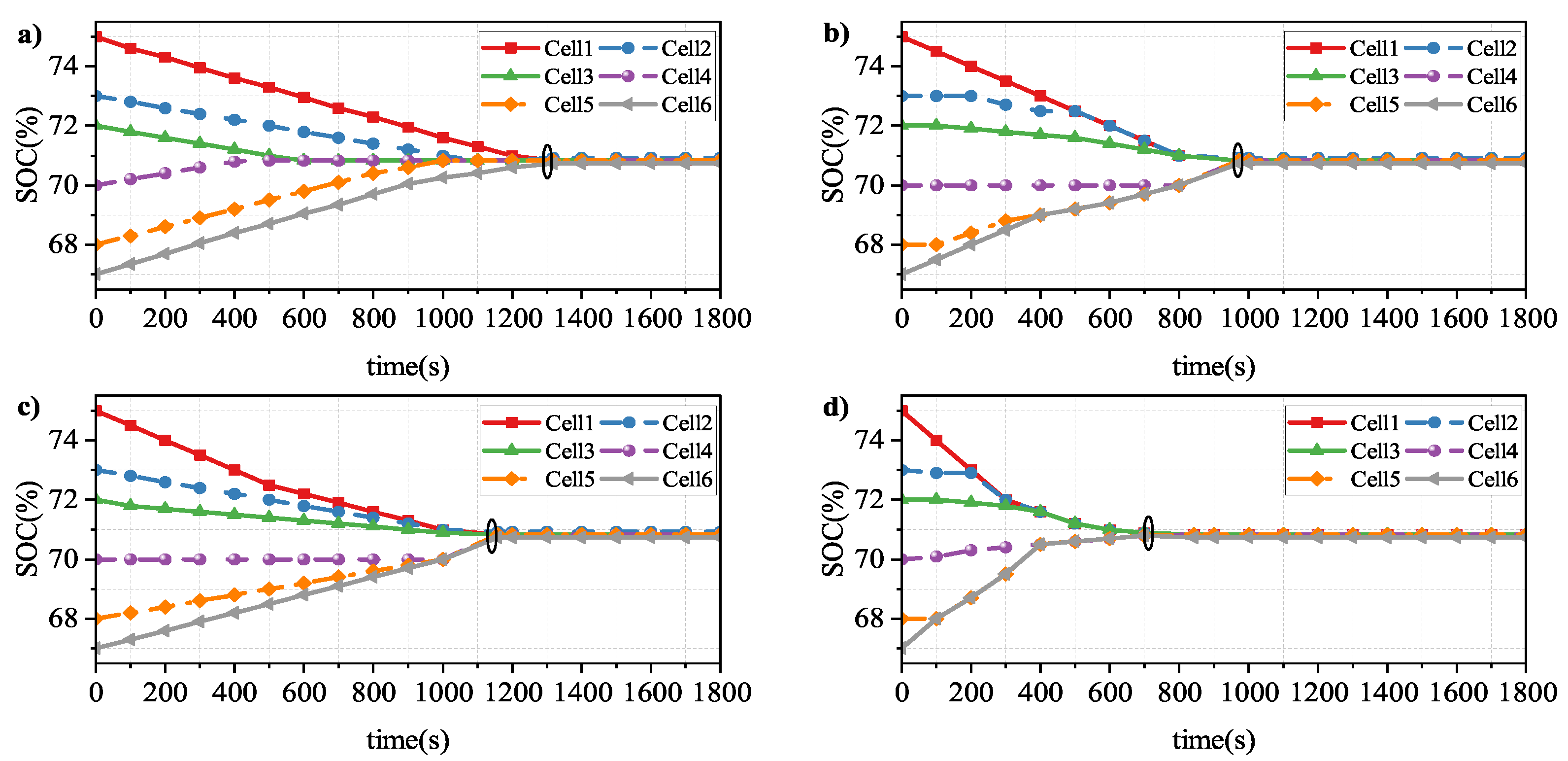
The initial SOC settings for each cell at quiescence are 75%, 73%, 72%, 70%, 68%, and 67%. As can be seen in Figure 10, the four circuits take 1269 s, 972 s, 1158 s, and 843 s to reach the equilibrium state, while the architecture proposed in this work takes the shortest times of 33.6%, 13.3% and 27.2%, respectively. Pattern 1 has the longest equalization path because it can only transmit energy between nearby cells, which results in the slowest equalization and increased energy loss. Both pattern 1 and pattern 2 have inductive structures with high circuit sizes, which increases power losses due to cell resistance values. Pattern 3 uses coupled inductors to share a single core, which reduces circuit energy losses, but its structure can only transmit energy between nearby cells, and in addition, the equalization results are not preferred. The proposed topology 4 uses coupled inductors to reduce energy losses, and it incorporates switching tubes to allow energy transmission between any number of individual cells, which significantly shortens the equalization path and equalizes C e l l 1 , C e l l 2 , C e l l 3 and C e l l 4 , C e l l 5 , and C e l l 6 , and after the relative equilibrium was reached within the pattern in about 200s, the intermodule equilibrium was started. It is worth noting that the pattern in this paper performs intramodule equalization as well as intermodule cell equalization, which further improves the equalization speed compared with the hierarchical Pattern 2, and therefore has the highest efficiency, as well as the extreme SOC difference values of 0.24%, 0.13%, 0.17%, and 0.09% for each cell in the four patterns after equalization, respectively. Regarding patterns 1, 2, and 3, the pattern suggested in this paper reduces the energy loss by 4.3%, 3.9%, and 4.2%, respectively.
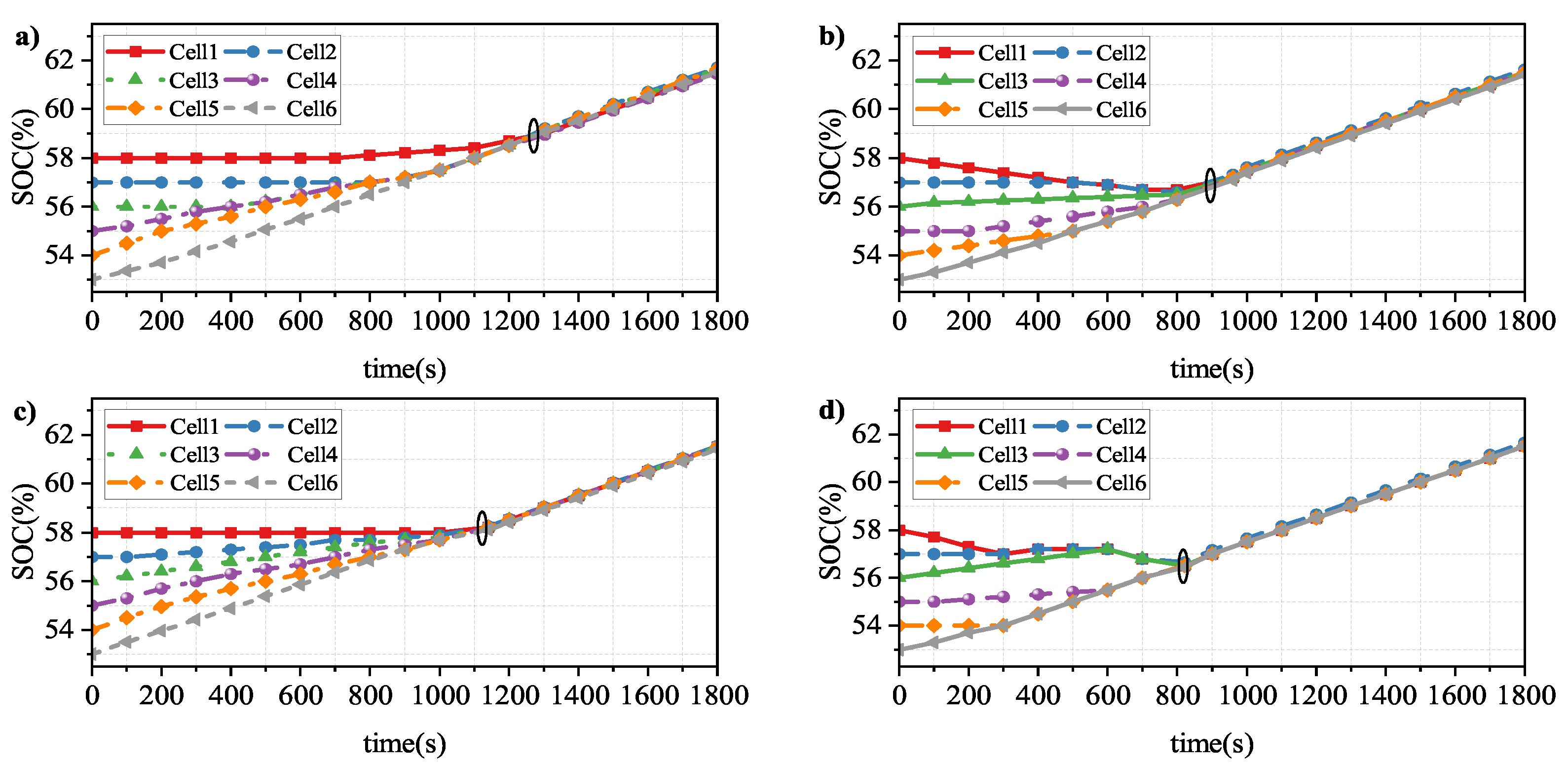
During charging, the original SOC values for each cell are set to 58%, 57%, 56%, 55%, 54%, and 53%, and as seen in Figure 11, the four circuits take 1258 s, 961 s, 1141 s, and 821 s to reach the equilibrium state, respectively, and the architecture provided in this work reduces the time by 34.7%, 14.6%, and 28%, respectively. After equilibrium, the values of the battery SOC polarization for the four patterns are 0.21%, 0.15%, 0.19%, and 0.11%, respectively, and the proposed pattern reduces the energy loss by 4.0%, 3.8%, and 3.9%, respectively.
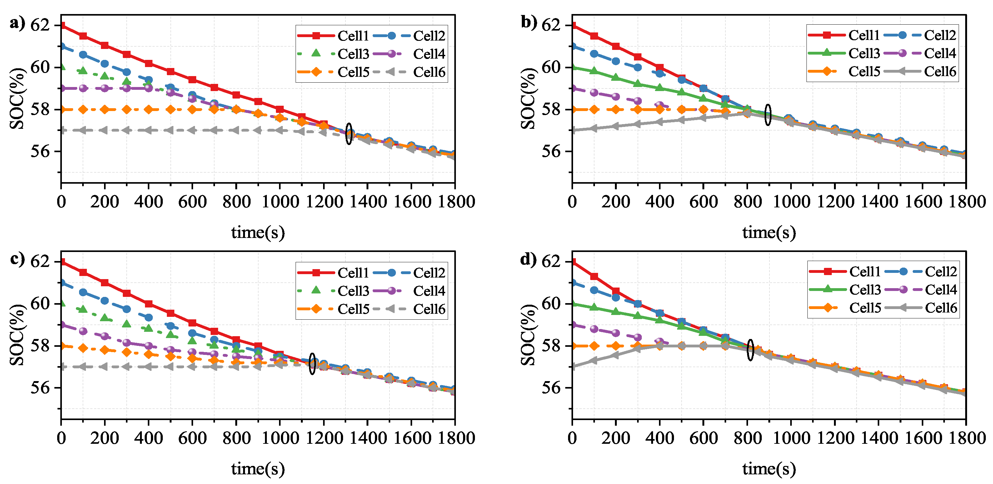
The initial SOCs of each cell in the discharged state are set to 62%, 61%, 60%, 59%, 58%, and 57%, and it can be seen from Figure 12 that the four circuits take 1271 s, 989 s, 1159 s, and 849 s to reach the equilibrium state, and the architecture provided in this work reduces the equilibrium time by approximately 33.2%, 14.2%, and 26.7%. After equilibrium, the extreme SOC difference values for each cell are 0.23%, 0.14%, 0.21%, and 0.10%, respectively, and the pattern given in this study reduces the energy loss by 3.8%, 3.5%, and 3.7%, respectively. In conclusion, the structure proposed in this paper is ideal in all three states. For a more visual presentation, the experimental data of the four patterns after equilibrium are listed in Table 4, Table 5 and Table 6, which show that the proposed framework can effectively solve the problem of inconsistency in the power group. 
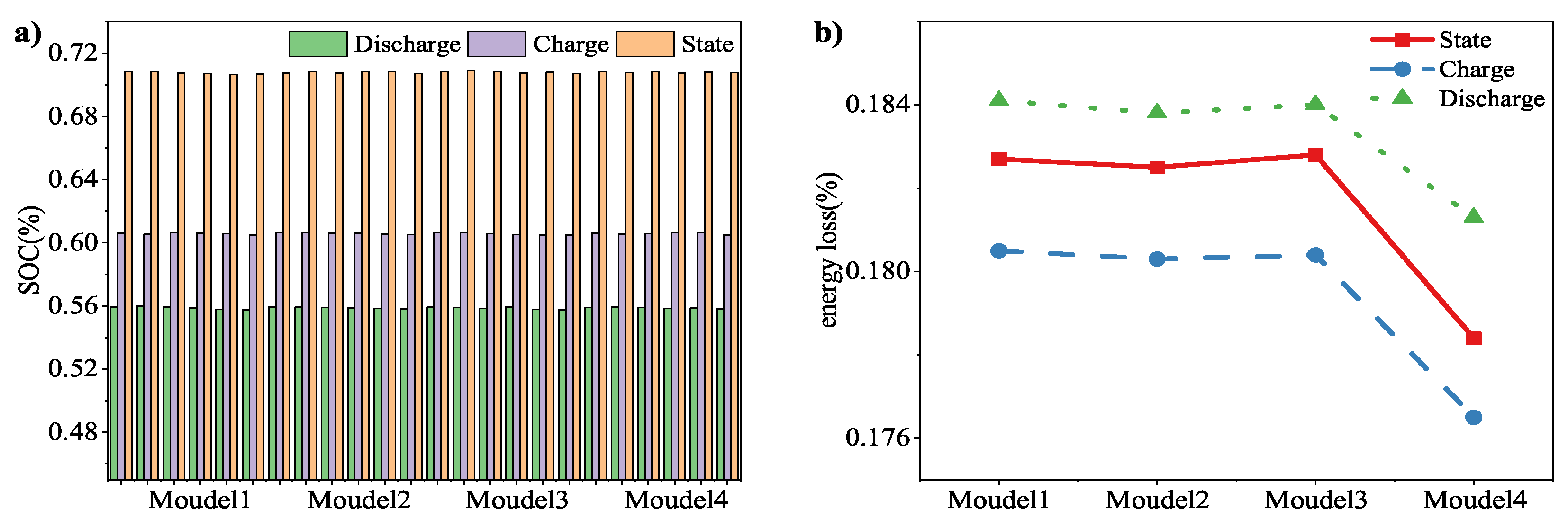
Figure 13 depicts the comparison findings for each mode after equalization.
To evaluate the topologies proposed in this paper more comprehensively, we also investigated the construction costs of the four topologies concerning the market price of electronic components in 2022, assuming the same price for the production cost of other measurement instruments, such as voltage and temperature, and taking a cell pack with 32 cells forming four modules as an example; the comparison results are shown in Table 7. Compared with other topologies, the structure proposed in this study reduces more than half of the capacitor and inductor components, despite the higher number of switches, and its overall cost is in the acceptable range. The price of the large-scale battery pack in the actual vehicle, with the increased use of capacitors and inductors, will be more expensive than the one with the addition of cheaper switches, which better reflects the cost advantage of the structure in this paper. In addition, the circuit works by controlling only the on and off of the switch P n in the BCEQ, which reduces the hardware resource requirements and also saves costs to a certain extent. When the amount of cells inside the unit gets higher, only the switch needs to be added, and the complexity of the circuit remains the same. 
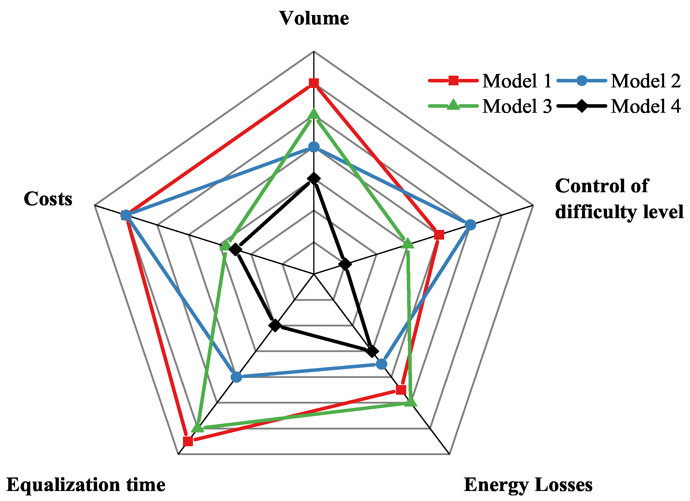
Figure 14 shows a comparison chart of all pattern information, and it is clear that the method proposed in this paper has an advantage in terms of equalization time, circuit size, construction cost, and control difficulty.

4.2. Equalization Control Strategy Verification

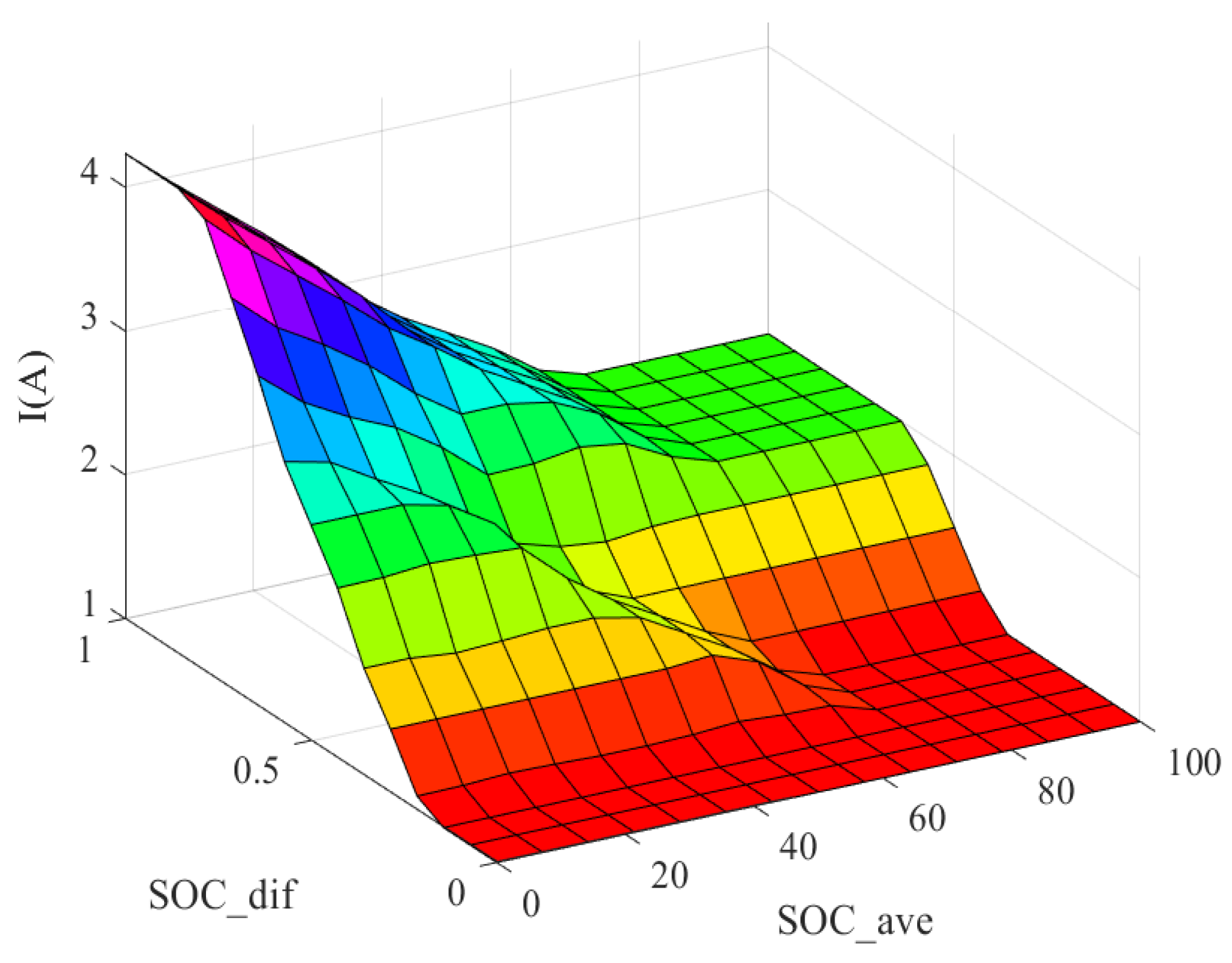
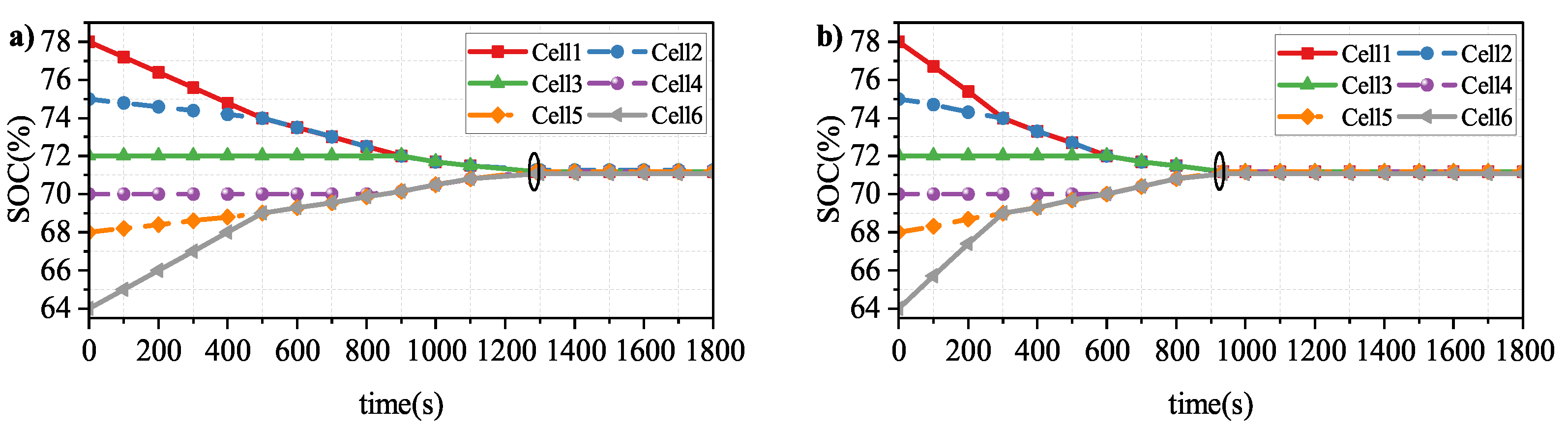
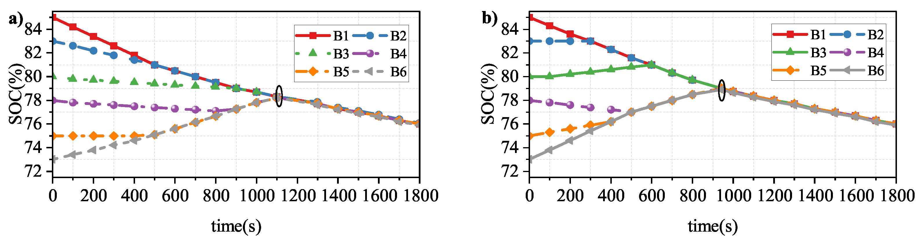
The VFPID introduces the concept of the variable theoretical domain based on FPID so that the input and output theoretical domains are adjusted in real-time with the change in the scaling factor, thus achieving adaptive change and better control accuracy for nonlinear and large lag systems. An in-module charge/discharge equalization simulation experiment is performed in this section, using VFPID and FPID to validate the superior performance of the method proposed in this paper. Charge and discharge with constant current and set the equalization current to 5A. Set the initial values of battery SOC to values with large differences for more visual observation, and set the initial SOC of each battery to 78%, 75%, 72%, 70%, 68%, and 64% in the static experiment for more visual observation. Such as in 
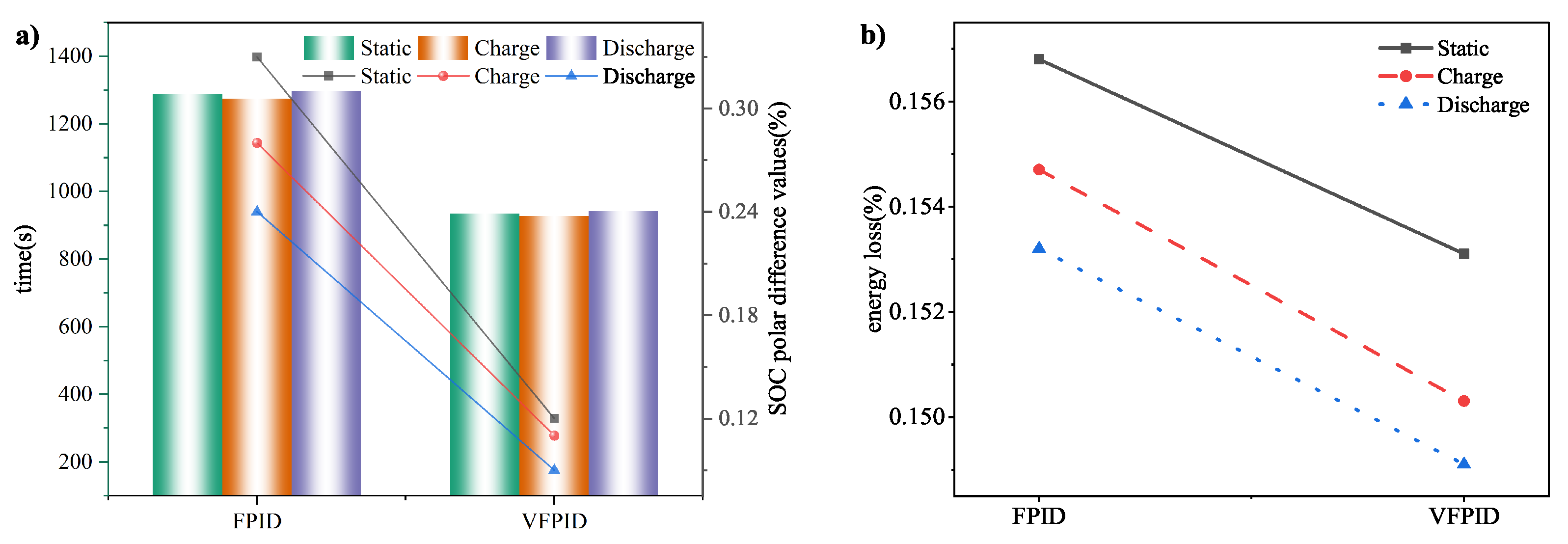
Figure 15, the three cells with the most charge were discharged at the beginning, while the cells with less charge were not. The equalization time of VFPID is about 935 s, while the equalization time of FPID is about 1289 s. The equalization speed is increased by 27.5%, and the extreme difference values of SOC of each cell after equalization are 0.33% and 0.12%, respectively. During charging, the original SOC values for each cell are set to 53%, 51%, 48%, 45%, 43%, and 41%. Such as in Figure 16, the equalization time of VFPID is about 927 s, while the equalization time of FPID is about 1274 s, which is 27.2% faster. The SOC extremes of each cell after equalization are 0.28% and 0.11%, respectively. During discharging, the original SOC values for each cell are set to 85%, 83%, 80%, 78%, 75%, and 73%. Such as in 
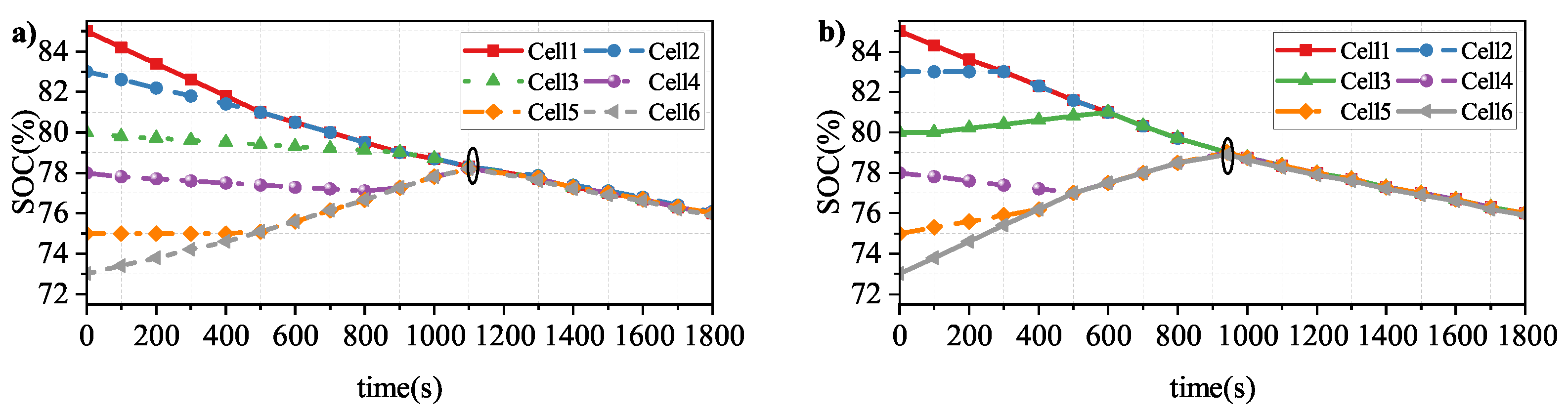
Figure 17, the VFPID equalization time is approximately 942 s, while the equalization time of FPID is about 1298 s, and the equalization speed is improved by 27.4%; the SOC pole values of each battery after equalization are 0.24% and 0.09%, respectively. Table 8 illustrates the SOC values of the cells after the equalization is completed by the two algorithms. Figure 18 shows the comparison of the SOC results of the equalized cells.

4.3. Verification of the Equalization Scheme under Dynamic DST Conditions

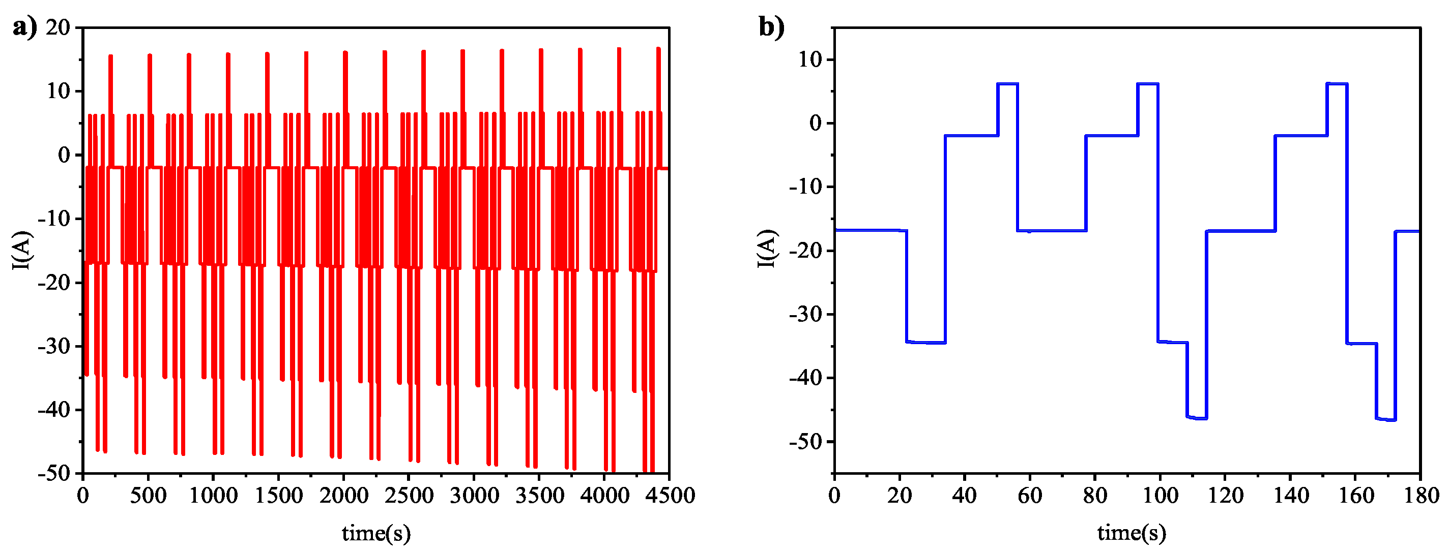
In the actual use of the vehicle, there is usually complex dynamic multiplier charging and discharging. Therefore, this section verifies the discharge of the four circuits in Section 4.1 under dynamic DST conditions, with the SOCs of each cell initially set to 62%, 61%, 60%, 59%, 58%, and 57%; Figure 19 shows the working discharge current during dynamic multiplier discharge with a discharge time of 3000 s, and Figure 20 demonstrates the equalization procedure. At the times of 1906 s, 1467 s, 1788 s, and 1318 s correspondingly, compared with other equilibration schemes, this study provides faster equilibration, saving time by 30.8%, 10.2%, and 26.3%, respectively, and the SOC pole difference values of each pattern cell after equilibrium are 0.35%, 0.27%, 0.31%, and 0.18%, respectively; the energy utilization percentages rose by 4.9%, 4.3%, and 4.5%, respectively, and the findings of the equalization tests are given in Table 9. Therefore, the equalization method proposed in the literature is equally applicable under dynamic conditions and can solve the problem of inconsistency of the cells and ensure the safe operation of the power pack.

5. Conclusions

A VFPID control approach is presented in the circuit in this paper, including a BCEQ structure that can equalize any single cell. Simulation is employed to confirm the structure’s dependability and the controlling algorithm’s supremacy. The findings demonstrate that the structure can effectively enhance equalization efficiency and minimize the time required for equalization, while the equalization algorithm can solve the problem of inconsistent battery packs and accomplish the intended outcomes. The following is a summary of the efforts undertaken by this essay:
(1) Transmission between any cells in the cell pack is made possible by the proposed equalization architecture; the designed structure reduces the number of components by half and the incorporated coupling inductor reduces the circuit size and lowers the circuit loss, while the circuit’s operating mode greatly saves hardware resources;
(2) The proposed VFPID equalization strategy is more flexible than the traditional FPID control strategy, which can make an adaptive evaluation of the battery state and then control the equalization current size, further improving the equalization time.
It is worthwhile to mention that, to address the obstacles that real vehicles would face in daily use, we can also conduct further research in the following areas:
(1) In the configuration of the equalizer, a hybrid equalization topology can be considered, such as the combined use of inductors and converters, thus allowing the circuit to obtain a more flexible and efficient energy utilization. Soft switching techniques can also be considered in the circuit to reduce the switching energy loss during energy transfer;
(2) Continued improvement of the precise method of estimating SOC, which enables the selection of phase control for voltage and cell SOC equalization targets due to the influence of Li-ion battery characteristics;
(3) Consider the influence of temperature factors when conducting the actual next test. Research can also be conducted on battery pack thermal equalization and other aspects.

Author Contributions

Conceptualization, Z.T. and X.W.; methodology, Z.T.; software, Z.T.; validation, L.C., X.W. and G.L.; formal analysis, G.L.; investigation, G.L.; resources, N.D.; data curation, G.L.; writing—original draft preparation, L.C.; writing—review and editing, X.W.; visualization, N.D.; supervision, L.C.; project administration, G.L.; funding acquisition, N.D. All authors have read and agreed to the published version of the manuscript.

Funding

This research was funded by the Natural Science Foundation of Chongqing, China (No. cstc2021jcyj-msxmX0301, No. CSTB2022NSCQ-MSX1675, and No. 2022NSCQ-MSX4086), Science and Technology Research Plan of Chongqing Municipal Education Commission (KJZD-K202101202, KJZD-K202103401).

Data Availability Statement

Not applicable.

Conflicts of Interest

The authors declare no conflict of interest.

Abbreviations

The following abbreviations are used in this manuscript:
BCEQBidirectional Cuk Equalizer
VFPIDVariable-domain fuzzy PID
FPIDFuzzy PID
DSTDynamic Stress Test
SOCState of Charge
PWMPulse Width Modulation
CCMContinuous Conduction Mode
UKFUnscented Kalman Filter

References

  1. Chen, Z.; Liao, W.; Li, P.; Tan, J.; Chen, Y. Simple and high-performance cell balancing control strategy. Energy Sci. Eng. 2022, 10, 3592–3601. [Google Scholar] [CrossRef]
  2. Wu, L.; Pang, K.; Zheng, Y.J.; Huang, P.; Chen, Y. A multi-module equalization system for lithium-ion battery packs. Int. J. Energy Res. 2022, 46, 2771–2782. [Google Scholar] [CrossRef]
  3. Du, G.; Zhang, G.; Yu, S.S.; Iu, H.H.; Lin, W.; Le, W.; Zhang, Y. An any-unit-to-any-unit method for hybrid-structured voltage equalizer in series-connected battery/super-capacitor strings. Int. J. Circuit Theory Appl. 2022, 50, 2016–2034. [Google Scholar] [CrossRef]
  4. Cui, H.; Wei, Z.; He, H.; Li, J. Novel reconfigurable topology-enabled hierarchical equalization of lithium-ion battery for maximum capacity utilization. IEEE Trans. Ind. Electron. 2023, 70, 396–406. [Google Scholar] [CrossRef]
  5. Geethanjali, S.; Vijayakumar, K. Testing and implementation of dual way DC-DC converter for electric vehicle power train system. IEICE Electron. Express 2022, 19, 20220343. [Google Scholar] [CrossRef]
  6. Fesenko, A.; Matiushkin, O.; Husev, O.; Vinnikov, D.; Strzelecki, R.; Kołodziejek, P. Design and Experimental Validation of a Single-Stage PV String Inverter with Optimal Number of Interleaved Buck-Boost Cells. Energies 2021, 14, 2448. [Google Scholar] [CrossRef]
  7. Liao, L.; Chen, H. Research on two-stage equalization strategy based on fuzzy logic control for lithium-ion battery packs. J. Energy Storage 2022, 50, 104321. [Google Scholar] [CrossRef]
  8. Li, Y.; Yin, P.; Chen, J. Active Equalization of Lithium-Ion Battery Based on Reconfigurable Topology. Appl. Sci. 2023, 13, 1154. [Google Scholar] [CrossRef]
  9. Ye, Y.; Cheng, K.W.E.; Fong, Y.C.; Xue, X.; Lin, J. Topology, modeling, and design of switched-capacitor-based cell balancing systems and their balancing exploration. IEEE Trans. Power Electron. 2016, 32, 4444–4454. [Google Scholar] [CrossRef]
  10. Miao, J.; Shen, C.; Bao, Y. Research on Bidirectional Active Equalization Control Strategy of Lithium Battery Pack for Energy Storage. In Proceedings of the 2019 IEEE 3rd International Electrical and Energy Conference (CIEEC), Beijing, China, 7–9 September 2019; pp. 658–661. [Google Scholar]
  11. Wei, Z.; Wang, H.; Lu, Y.; Shu, D.; Ning, G.; Fu, M. Bidirectional Constant Current String-to-Cell Battery Equalizer Based on L2C3 Resonant Topology. IEEE Trans. Power Electron. 2022, 38, 666–677. [Google Scholar] [CrossRef]
  12. Turksoy, A.; Teke, A. A fast and energy-efficient nonnegative least square-based optimal active battery balancing control strategy for electric vehicle applications. Energy 2023, 262, 125409. [Google Scholar] [CrossRef]
  13. Habib, A.A.; Hasan, M.K.; Islam, S.; Ahmed, M.M.; Aman, A.H.M.; Bagwari, A.; Khan, S. Voltage equalization circuit for retired batteries for energy storage applications. Energy Rep. 2022, 8, 367–374. [Google Scholar] [CrossRef]
  14. Dam, S.K.; John, V. Low-frequency selection switch based cell-to-cell battery voltage equalizer with reduced switch count. IEEE Trans. Ind. Appl. 2021, 14, 2448. [Google Scholar] [CrossRef]
  15. Xiong, H.; Song, D.; Shi, F.; Wei, Y.; Jinzhen, L. Novel voltage equalisation circuit of the lithium battery pack based on bidirectional flyback converter. IET Power Electron. 2020, 13, 2194–2200. [Google Scholar] [CrossRef]
  16. Liao, L.; Chen, H.; Sun, S.; Li, H.; Jiang, J.; Wu, T. Research on Equalization Strategy Based on Credibility Factor Inference for Lithium-Ion Battery Packs. IEEE Access 2022, 10, 107980–107992. [Google Scholar] [CrossRef]
  17. Feng, F.; Song, B.; Xu, J.; Na, W.; Zhang, K.; Chai, Y. Multiple time scale state-of-charge and capacity-based equalisation strategy for lithium-ion battery pack with passive equaliser. J. Energy Storage 2022, 53, 105196. [Google Scholar] [CrossRef]
  18. Li, P.; Liu, J.; Deng, Z.; Yang, Y.; Lin, X.; Couture, J.; Hu, X. Increasing energy utilization of battery energy storage via active multivariable fusion-driven balancing. Energy 2022, 243, 122772. [Google Scholar] [CrossRef]
  19. Kamel, M.; Sankaranarayanan, V.; Zane, R.; Maksimović, D. State-of-charge balancing with parallel and series output connected battery power modules. IEEE Trans. Power Electron. 2022, 37, 6669–6677. [Google Scholar] [CrossRef]
  20. Cui, X. Online temperature distribution estimation of lithium-ion battery considering non-uniform heat generation characteristics under boundary cooling. Appl. Therm. Eng. 2023, 225, 120206. [Google Scholar] [CrossRef]
  21. Galvão, J.R.; Calligaris, L.B.; de Souza, K.M.; Gotz, J.D.; Junior, P.B.; Corrêa, F.C. Hybrid Equalization Topology for Battery Management Systems Applied to an Electric Vehicle Model. Batteries 2022, 8, 178. [Google Scholar] [CrossRef]
  22. Barreras, J.V.; de Castro, R.; Wan, Y.; Dragicevic, T. A consensus algorithm for multi-objective battery balancing. Energies 2021, 14, 4279. [Google Scholar] [CrossRef]
  23. Ouyang, Q.; Zhang, Y.; Ghaeminezhad, N.; Chen, J.; Wang, Z.; Hu, X.; Li, J. Module-based active equalization for battery packs: A two-layer model predictive control strategy. IEEE Trans. Transp. Electrif. 2021, 8, 149–159. [Google Scholar] [CrossRef]
  24. Lin, J.; Yang, X.; Zhou, J.; Wang, G.; Liu, J.; Yuan, Y. Algorithm of BPNN-UKF based on a fusion model for SOC estimation in lithium-ion batteries. IET Power Electron. 2022, 1–12. [Google Scholar] [CrossRef]
  25. Zhang, X.; Zhang, R. Estimation of Lithium Battery SOC Based on Fuzzy Unscented Kalman Filter Algorithm. In Proceedings of the 2021 IEEE/IAS Industrial and Commercial Power System Asia (ICPS Asia), Chengdu, China, 18–21 July 2021; pp. 200–204. [Google Scholar]
  26. Wu, T.; Qi, Y.; Liao, L.; Ji, F.; Chen, H. Research on equalization strategy of lithium-ion batteries based on fuzzy logic control. J. Energy Storage 2021, 40, 102722. [Google Scholar] [CrossRef]
  27. Yang, D.; Wang, F.; Qian, K.; Jiao, Z. Research on charge-discharge equalization strategy of aviation battery based on Gaussian variation function. In Proceedings of the 2021 IEEE 2nd International Conference on Information Technology, Big Data and Artificial Intelligence (ICIBA), Chongqing, China, 17–19 December 2021; pp. 819–822. [Google Scholar]
  28. Nie, W.; Chen, Z. Composite Active Equilibrium Method for Lithium Ion Battery Pack. In Proceedings of the 2019 IEEE 3rd International Electrical and Energy Conference (CIEEC), Beijing, China, 7–9 September 2019; pp. 1071–1075. [Google Scholar]
  29. Farzan Moghaddam, A.; Van den Bossche, A. A Ćuk converter cell balancing technique by using coupled inductors for lithium-based batteries. Energies 2019, 12, 2881. [Google Scholar] [CrossRef] [Green Version]
Figure 1. Overall structure of the equalization scenario.
Wevj 14 00086 g001
Figure 2. Internal structure of the module.
Wevj 14 00086 g002
Figure 3. Energy transfer in a balanced topology: (a) Intramodule; (b) Intermodule.
Wevj 14 00086 g003
Figure 4. (a) Bidirectional Cuk converter; (b) simplified circuit; (c) Stage 1 operating state; and (d) Stage 2 operating state.
Wevj 14 00086 g004
Figure 5. (a) Physical circuit diagram and (b) waveforms of switching control signal and inductor current.
Wevj 14 00086 g005
Figure 6. Equalization control flow chart.
Wevj 14 00086 g006
Figure 7. (a) SOC estimation curve based on UKF algorithm and (b) Error.
Wevj 14 00086 g007
Figure 8. (a) Affiliation function of S O C a v e ; (b) Affiliation function of S O C d i f ; (c) Affiliation function of I.
Wevj 14 00086 g008
Figure 9. Three-dimensional relational surfaces.
Wevj 14 00086 g009
Figure 10. Equilibrium process of the four circuits in the static state: (a) Pattern 1; (b) Pattern 2; (c) Pattern 3; and (d) Pattern 4.
Wevj 14 00086 g010
Figure 11. Equalization process of four circuits in charging state: (a) Pattern 1; (b) Pattern 2; (c) Pattern 3; and (d) Pattern 4.
Wevj 14 00086 g011
Figure 12. Equalization process of the four circuits in the discharged state: (a) Pattern 1; (b) Pattern 2; (c) Pattern 3; and (d) Pattern 4.
Wevj 14 00086 g012
Figure 13. Comparison of equilibrium results: (a) Battery SOC values at the end of equilibrium for the four patterns; (b) Energy Losses.
Wevj 14 00086 g013
Figure 14. Equilibrium process of the four circuits in the static state.
Wevj 14 00086 g014
Figure 15. The equalization process of FPID and VFPID in the static state: (a) FPID; (b) VFPID.
Wevj 14 00086 g015
Figure 16. The equalization process of FPID and VFPID in charging state: (a) FPID; (b) VFPID.
Wevj 14 00086 g016
Figure 17. The equalization process of FPID and VFPID in the discharged state: (a) FPID; (b) VFPID.
Wevj 14 00086 g017
Figure 18. Comparison of equilibrium results: (a) Equalization time and SOC polarization value; (b) Energy Losses.
Wevj 14 00086 g018
Figure 19. (a) DST working condition and (b) Discharge current.
Wevj 14 00086 g019
Figure 20. Discharge equalization process under dynamic DST condition: (a) Pattern 1; (b) Pattern 2; (c) Pattern 3; and (d) Pattern 4.
Wevj 14 00086 g020
Table 1. Input and output fuzzy rules.
I Δ SOC
XSSMLVL
S O C ¯ SXSXSMLVL
MXSSMML
LSSSMM
Table 2. Values for parameter adjustments Δ k p , Δ k i , and Δ k d fuzzy rules.
Δ k p / Δ k i / Δ k d Δ SOC
XSSMLVL
S O C ¯ SXS/S/VLS/S/VLM/M/VLL/L/VLVL/VL/VL
MS/L/LS/VL/MVL/VL/VLVL/VL/ML/VL/M
LM/S/SM/S/SVL/S/SVL/M/SL/M/S
Table 3. Model parameter values.
ParametersValues
Nominal battery voltage3.7 V
Battery Capacity50 Ah
Inductor L 1 a , L 1 b , L 2 a , L 2 b 100 μH
Capacitor C 1 a , C 1 b 20 μF
Turn on the balanced SOC value2%
Table 4. Static equalization experimental data.
Battery Serial NumberPattern 1Pattern 2Pattern 3Pattern 4
B170.83%70.74%70.85%70.83%
B270.87%70.81%70.89%70.76%
B370.73%70.75%70.84%70.81%
B470.71%70.83%70.75%70.74%
B570.63%70.85%70.78%70.80%
B670.67%70.72%70.71%70.77%
Table 5. Charge equalization experimental data.
Battery Serial NumberPattern 1Pattern 2Pattern 3Pattern 4
B160.63%60.65%60.64%61.61%
B260.54%60.66%60.67%60.55%
B360.68%60.63%60.57%60.57%
B460.60%60.59%60.53%61.66%
B560.57%60.55%60.49%61.64%
B660.47%60.51%60.48%61.50%
Table 6. Discharge equalization experimental data.
Battery Serial NumberPattern 1Pattern 2Pattern 3Pattern 4
B155.95%55.94%55.91%55.90%
B255.99%55.91%55.89%55.91%
B355.91%55.90%55.85%55.89%
B455.86%55.86%55.93%55.85%
B555.79%55.84%55.79%55.87%
B655.77%55.80%55.75%55.81%
Table 7. Discharge equalization experimental data.
Component NumberPattern 1Pattern 2Pattern 3Pattern 4
Inductors4848208
Capacitors48481616
Switch486432128
Establishment Costs(USD)3335.43337.431893174.8
Table 8. Equalization experimental data.
Battery NumberFPIDVFPID
StaticChargeDischargeStaticChargeDischarge
B171.45%52.53%70.31%71.38%52.34%76.17%
B271.39%52.51%76.27%71.33%52.32%76.15%
B371.32%52.47%76.25%71.28%52.30%76.14%
B471.27%52.36%76.21%71.25%52.27%76.11%
B571.21%52.29%76.14%71.19%52.24%76.09%
B671.12%52.25%76.07%71.16%52.23%76.08%
Table 9. Discharge equalization experimental data.
Battery Serial NumberPattern 1Pattern 2Pattern 3Pattern 4
B155.87%55.85%55.86%55.78%
B255.85%55.82%55.84%55.75%
B355.77%55.80%55.73%55.73%
B455.69%55.76%55.66%55.71%
B555.65%55.68%55.59%55.64%
B655.52%55.58%55.55%55.60%
Disclaimer/Publisher’s Note: The statements, opinions and data contained in all publications are solely those of the individual author(s) and contributor(s) and not of MDPI and/or the editor(s). MDPI and/or the editor(s) disclaim responsibility for any injury to people or property resulting from any ideas, methods, instructions or products referred to in the content.

