1. Introduction
Unmanned platforms include unmanned aerial vehicles, unmanned boats, unmanned submersibles and ground unmanned vehicles. Unmanned ground vehicles are also called autonomous ground vehicles and autonomous ground mobile robots. With the rapid development of advanced smart sensors, fast response actuators, high-performance ECUs, advanced control strategies, computer-based network technology, radar technology, mobile communication technology and other advanced technologies, intelligent driving vehicles have stepped from conceptualization to production [
1]. With the fast growth of social productivity and automobile technology, the number of cars is increasing progressively year after year, and the traffic problem of traditional drivers driving cars is also increasing. Unmanned technology and unmanned vehicles are the developmental result of the human automobile industry [
2], which represents the highest technical level in the field of automobile research [
3], and it is also the future development trend of automobiles. In addition, with the advancement of conventional unmanned vehicle technology, the unmanned trend of formula car is increasingly obvious. The longitudinal control system, which is one of the key technologies of unmanned racing, is the basis for the realization of unmanned formula racing [
4]. Thus, the design of control methods with high stability and reliability is of great significance.
Vehicle motion control technology is the most key technology for unmanned intelligent vehicle at this stage, and it is the basis to realize stable, reliable and autonomous driving of vehicles. Motion control involves unmanned vehicle dynamics theory and is an important content of unmanned vehicle technology [
5]. In accordance with environmental information obtained by the vehicle perception layer, the vehicle acceleration, braking, steering and other systems are under automatic control. So, the vehicle is controlled to drive in accordance with desired path. Unmanned vehicle motion control can be either longitudinal or lateral control. Additionally, these two types are different and correlated. Lateral control, in essence, refers to the control of the unmanned vehicle’s steering angle, mainly considering the safety and stability of controlled vehicle [
6]. Longitudinal control mainly refers to the control of unmanned vehicle’s speed and distance. The purpose is to make the controlled vehicles drive at the expected speed or maintain the expected distance. Unmanned vehicle is a highly integrated nonlinear system [
7]. There are many interactive and restrictive factors between lateral and longitudinal control systems. Therefore, the design of lateral or longitudinal control system cannot satisfy an unmanned vehicle’s actual driving requirements alone. During actual driving of the vehicle, various driving conditions need to take into account the lateral and longitudinal movements [
8]. For example, the direction and speed of the vehicle need to be controlled at the same time in sharp corners, overtaking, parking alongside and other situations. Most unmanned vehicles only combine lateral and longitudinal control without coupling them, and do not take into account the interaction between lateral and longitudinal dynamics and kinematics. Therefore, the control effect is not ideal. During driving of an unmanned vehicle, there is a complex and strong coupling relationship between longitudinal direction and lateral direction [
9]. The whole vehicle is a highly nonlinear motion constraint system, and its model and environment have uncertainty and measurement inaccuracy, which makes the lateral and longitudinal control more complex. Designing the lateral control or longitudinal control system of intelligent vehicle cannot satisfy the intelligent vehicle’s driving needs alone. Simple working conditions should be designed to move laterally and longitudinally at the same time, so that actions such as overtaking, pulling over and so on can be carried out. Most vehicle control systems are synthesized based on the simultaneous loading of lateral and longitudinal independent controllers [
10]. However, since the interaction of lateral and longitudinal dynamics is not considered in the dynamic modeling, and such a vehicle control effect is not necessarily the same as that in the independent control.
Numerous scholars have carried out intensive research and achieved certain results. Research shows that most control methods need high-precision vehicle models or complex optimization algorithms to optimize the controller. Ge L and his team used MPC to directly solve the longitudinal and lateral coupling control problems, and used convex optimization methods to solve the reference value problem of predictive control. Additionally, they proposed a systematic method to prevent the reference value from exceeding the feasible region. The research results showed that the algorithm could solve the lateral and longitudinal disturbance problems. Because longitudinal and lateral coupling constraints are considered, the algorithm has better tracking accuracy and high-speed stability [
11]. Wang, Y and their team proposed an integrated algorithm for longitudinal and lateral trajectory planning and tracking control based on vehicle to vehicle communication. The algorithm includes two levels: trajectory planning and path tracking control. A three-step nonlinear method of multi input and multi output is proposed to design longitudinal and lateral path tracking controllers. Finally, the stability of the closed-loop system is strictly proved based on Lyapunov function, and the effectiveness of the algorithm is verified through a high fidelity full vehicle model on the veDYNA (Vehicle dynamics) platform [
12]. To sum up, the research on the control algorithm of driverless vehicles has made certain achievements. The control system of driverless vehicles is not just composed of a simple longitudinal and lateral independent control system. To have sufficient practical value in practical projects, it is necessary to consider the interaction between the longitudinal and lateral directions of vehicles. The lateral and longitudinal control can improve the path tracking ability of the driverless car. The previous lateral and longitudinal control only considered the parameters that affect each other between the lateral control and longitudinal control directions. Additionally, it did not take into account the actual working conditions.
Therefore, based on the study of lateral and longitudinal control, this paper proposes a lateral and longitudinal control method that takes into account various actual working conditions of a driverless car. It aims to improve the path tracking control effect of driverless cars. The research contribution is as follows: (1) the proposal of driverless electric formula racing is to promote the development of driverless control technology. (2) It is proposed that the driverless control method considering horizontal and vertical directions can achieve intelligent control of driverless racing through coordinated control, which is of great significance to the development of driverless technology. (3) In addition, the performance of driverless control technology is verified with the help of driverless electric formula racing, which provides ideas for the intelligent development of transportation. Additionally, the innovation points in this study are (1) a lateral controller based on a fuzzy neural network; (2) a racing longitudinal controller based on an incremental PID; (3) the coordination controller of the transverse and longitudinal direction of the racing car is proposed; (4) the effectiveness of the controller is verified by simulation experiments.
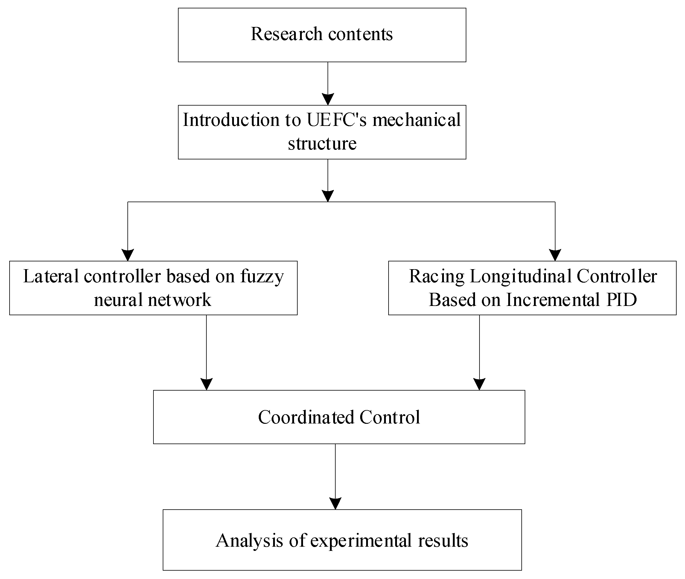
The main contents of this study are shown in
Figure 1. Firstly, the mechanical structure of UEFC is briefly introduced, and then the mathematical model of UEFC is analyzed. At the same time, the lateral controller based on the fuzzy neural network and the longitudinal controller of the racing car based on incremental PID are proposed. Then, the lateral and longitudinal controllers of UEFC are proposed according to the abovementioned research. Finally, the proposed research methods are verified and analyzed by experiments.
2. Materials and Methods
2.1. Introduction to UEFC’s Mechanical Structure
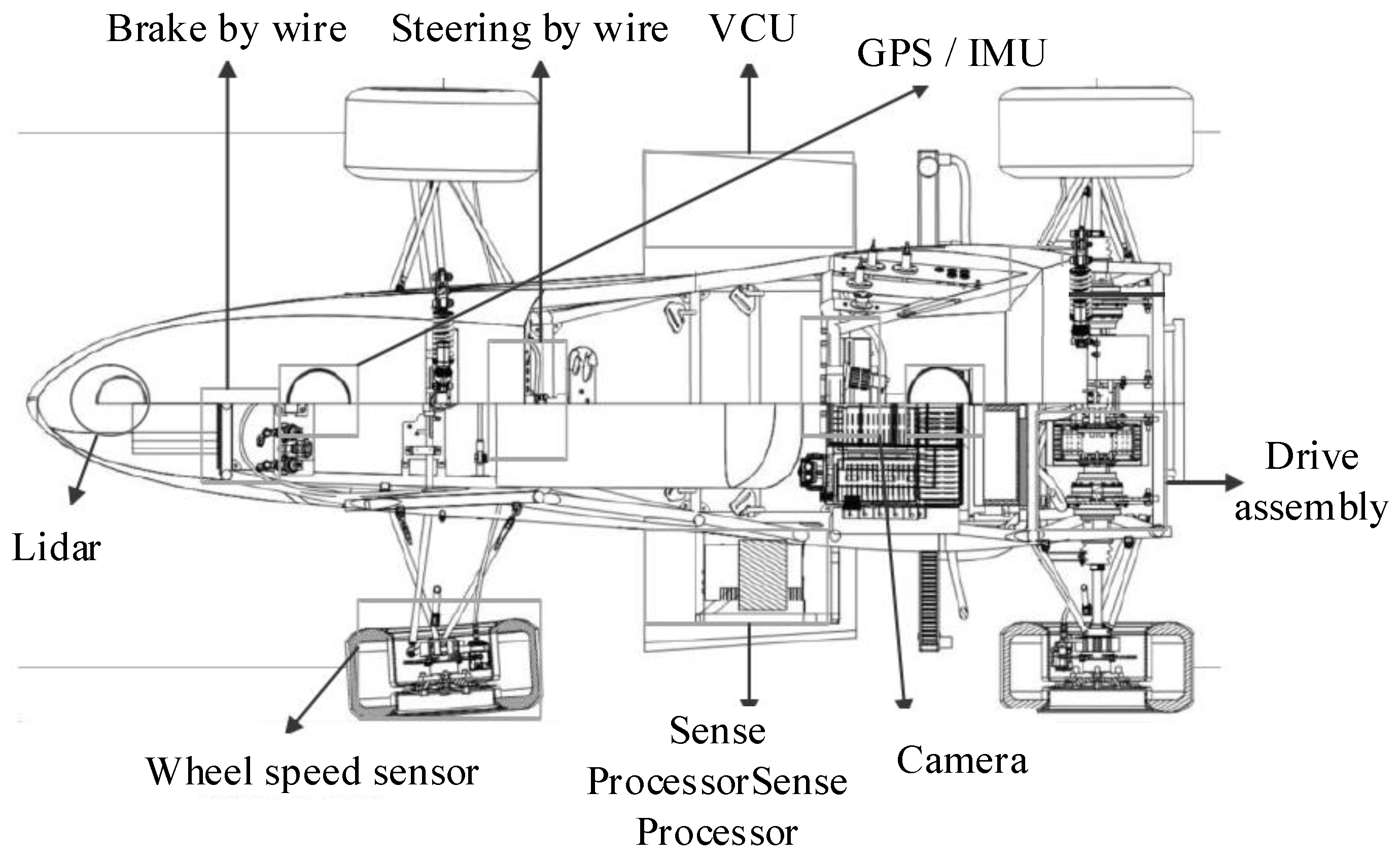
On the basis of the electric formula racing car, the driverless electric formula racing car is composed of environment sensing system and wire control mechanism. The whole car conforms to the vehicle system dynamics. The environment awareness system consists of a series of sensors and processors such as cameras, laser radars, GPS/INS, etc. These components are responsible for sensing the environment around the racing track and the real-time status of the racing car. At the same time, these components are responsible for planning the corresponding reference path through algorithms. The control by wire system is composed of steering by wire, drive by wire and brake by wire. The vehicle controller is used to coordinate and control the executive components of the wire control system. The vehicle controller receives the data from the perception system and processes it to get the control command. According to the command, each part of the wire control system makes corresponding actions to complete the tracking control of the car. In order to improve the path tracking accuracy of the car, this chapter introduces a hardware structure and software structure of the car. At the same time, this chapter analyzes the role of each part as well as the design and calculation process for the research of driverless car’s control strategy. The hardware structure of the unmanned system is composed of sensing sensor, wire control mechanism, processor, controller, etc. Perceptual data processing, mapping and planning, and control constitute the software structure of the unmanned system. At the same time, in order to ensure the accuracy and stability of the driverless car in the lateral and longitudinal control, the vehicle dynamics model, tire model, motor model, etc. are built.
Figure 2 shows the mechanical structure of UEFC [
13].
By obtaining and storing the racing point cloud information through the cone barrel, the perceptual data processes the point cloud information from the LiDAR acquisition cone barrel, and uses the point cloud filtering algorithm to filter and identify the target cone barrel point cloud. The camera collects the cone barrel color information, and uses the depth learning mode to accurately identify the target cone barrel color. The joint calibration algorithm of LiDAR and camera is designed independently. The 3D LiDAR point cloud data is mapped to the image through the internal and external parameter transformation matrix through timestamp matching, and finally the data fusion between the two sensors is realized.
The drive-by-wire drive system of driverless racing car is partially driven by two independent motors, which can improve the controllability of the racing car. The torque output of each motor can be controlled separately according to the actual working conditions to improve the dynamic performance of the racing car. The vehicle controller sends the torque command calculated by the algorithm to the motor controller through CAN communication to realize the drive-by-wire control of the driverless racing car. For steering-by-wire, on the basis of ensuring the original mechanical steering, a drive motor is added in the middle of the steering shaft to realize steering-by-wire. In order to facilitate the disassembly of the brake drive system and integrate the assembly, the brake drive motor mounting frame is designed. Two connecting rods are used between the motor and the brake pedal to transmit the torque of the motor so that the brake pedal can rotate and brake. There is an empty stroke structure between the motor and the drive connecting rod. When the driver steps on the brake, the drive connecting rod rotates relative to the empty stroke of the motor, ensuring that it is not interfered by the motor. The motor and connecting rod are connected with flat keys, and the two connecting rods are connected with bolts. When the motor brakes, the connecting rod is connected with the motor rotates, which drives the brake pedal to rotate for braking. After braking, the brake pedal is reset under the action of the brake master cylinder.
This research is the basis of the longitudinal and transverse controller’s design. In order to have a better understanding of the driverless car, its structural design is given. Considering the control accuracy and complex working conditions of the driverless car, three degree of freedom dynamics model of the whole car is used, and the tire model of the car is established.
2.2. Mathematical Model of UEFC
As the track is smooth and dry asphalt pavement, and no driver is allowed to sit in the car when the car is driverless. No in-depth study is made on the suspension system that affects the ride comfort of the car [
14]. According to the above analysis, when modeling the vehicle dynamics, the plane motion of the car is mainly considered in two directions, namely, lateral and yaw motion. Therefore, a three-degree-of-freedom vehicle monorail dynamics model is established.
(4) Rotational movement of four wheels
In the formulas, refers to the vehicle mass; refers to the front wheel angle; refers to the inertia moment of the vehicle; and refer to the distance from the front axis and rear axis of the vehicle to the mass center respectively; refer to the longitudinal speed; refer to the lateral velocity; refers to the yaw rate. , , , , , , and respectively refer to the front right, front left, rear right and rear left tire force components along the lateral direction; refers to the track width of left and right wheels (given that the front and rear wheels’ track widths are equal); refers to the rolling inertia moment of the wheel; refers to the angular velocity of the wheel; refers to the braking torque of the wheel (, refers to the front wheel and rear wheel, , refers to the left wheel and right wheel, the same below); is the rear wheel drive torque; is the wheel’s longitudinal force; and is the wheel’s rolling radius.
In the actual process, the tire structure is more complex, and the dynamic characteristics are nonlinear. The steering characteristics and driving stability of the racing car are closely related to the nonlinear characteristics of the tire. Therefore, appropriate tire model plays a key role in establishing vehicle model and conducting dynamic simulation, i.e., real vehicle control.
The magic tyre formula has the characteristics of unity, convenient fitting and high fitting accuracy. Besides, its parameters can be easily determined. Therefore, the formula is widely accepted by researchers and engineers in the automotive industry. The empirical tire model based on the magic formula is adopted in this paper, as shown in Formula (5) [
15].
In Formula (4): Y is the output variable, which can be represented by the longitudinal force Fl or the lateral force Fc or the return moment Mz; x is the input variable, which can be determined by the tire side slip angle α or longitudinal slip ratio s; B. C, D and E are stiffness factor, shape factor, peak factor and curvature factor, respectively.
2.3. Lateral Controller Based on Fuzzy Neural Network
2.3.1. Torque Control Layer
The stability of UEFC can be evaluated with the deviation of yaw rate and the deviation of the centroid side deflection angle. The smaller deviation will lead to stable control better. The yaw moment control layer adopts fuzzy neural network algorithm. A five layer fuzzy neural network is adopted [
16]. The input layer includes the deviation
of yaw rate and the deviation
of centroid side deflection angle. The output layer is the yaw moment
, and the membership functions of the input and output layers are Gaussian functions. By comparing the yaw moment
with the maximum yaw moment
provided by the ground, the final yaw moment
is obtained for controlling the UEFC. Fuzzy neural network can quickly and effectively calculate the optimal parameters of membership function by learning the relationship between input variables
,
and output variable
. Additionally, 30 fuzzy rule statements can be generated to form the fuzzy rules of the controller. During the driving of the UEFC, the fuzzy neural network controller will apply a yaw moment to the UEFC to make the vehicle drive stably [
17]. If the torque exceeds the torque limit of the ground acting on the wheel, the wheel will slip excessively, so the yaw moment needs to be limited. The maximum yaw moment that the ground can provide is shown in Formula (6).
In Formula (6),
is the track width;
are the longitudinal force of the right front, rear wheels, the left front and rear wheels respectively. In accordance with comparison between the yaw moment output by the fuzzy neural network and the maximum yaw moment that can be provided by the ground, the smaller moment is selected as the final yaw moment
, and the expression is as follows:
2.3.2. Distribution of Torque and Control Layer of Slip Rate
To distribute the torque to the driving wheel, the distribution of torque and the control layer of slip rate receive the expected torque and the yaw torque output by the yaw control layer. Additionally, it should take into account the factors of motor failure and driving wheel slip ratio. In case of motor failure, the driving wheels on both sides will output different torques, which will lead to difficult tracking or even out of control [
18]. If the slip rate of the vehicle is too large, it is easy to cause the vehicle out of control and accidents. Therefore, the factors of motor failure and slip rate should be considered in the torque distribution strategy to ensure the vehicle’s stable driving.
- (1)
Torque distribution and restraint
To ensure the vehicle’s stability, a target yaw moment
is used to control the driving wheel torque. In the process of turning, the tire on the same side as the steering wheel is called the inside wheel, which turns differently and is interchangeable inside and outside. As for tires, the side facing the outside of the vehicle body is the outside of the tyres. It is controlled by increasing
for the outer wheel and decreasing
for the inner wheel.
is calculated as follows:
In Formula (8), refers to the racing car’s tire radius.
Considering the limitation of the maximum torque of the motor, the expected torque of the driving wheels on both sides is shown in Formula (9).
In the formula, and represent the actual output torque of internal and external motors respectively; and respectively indicate the maximum torque that the inner and outer sides of the motor can output at this time; refers to the motor’s rated speed; refers to the motor’s actual speed.
- (2)
Motor failure
In case of failure, the motor will send a fault code to the motor controller. According to different fault levels, the motor fault factor
needs to be designed to restrict the torque of the driving wheel and prevent damage to the motor and driver. The range of fault factor
is [0, 1]; 0 indicates that the motor has the highest fault level: the motor fails and needs to be stopped immediately; 1 indicates that the motor has no fault and operates normally. The fault level of the motor is judged by the fault code sent by the motor encoder to the motor controller. Under the constraint of motor fault factor, the output torque of inner and outer drive wheels is
- (3)
Slip rate control
In accordance with actual conditions of road, set the target slip rate to [0.06, 0.22]. The slip ratio
of the tire on the ground can be expressed by Formula (13).
In Formula (13),
is the wheel radius,
is the wheel rotation angle speed,
is the tire speed. When the slip rate of the motor exceeds the slip rate set by the logic, the torque PID control of the motor will be started, and the difference of slip rate is taken as the input to adjust the motor torque output.
In the formula,
and
respectively are the minimum value and the maximum value of the target slip rate range;
is the target slip rate representing the actual slip rate. In the algorithm of PID control, the motor torque after adjustment is
In the formula,
,
and
respectively are proportional coefficient, integral coefficient and differential coefficient. The UEFC’s final torque output is as follows:
In Formula (16), and are the torques of the inner and outer wheels of the UEFC, respectively.
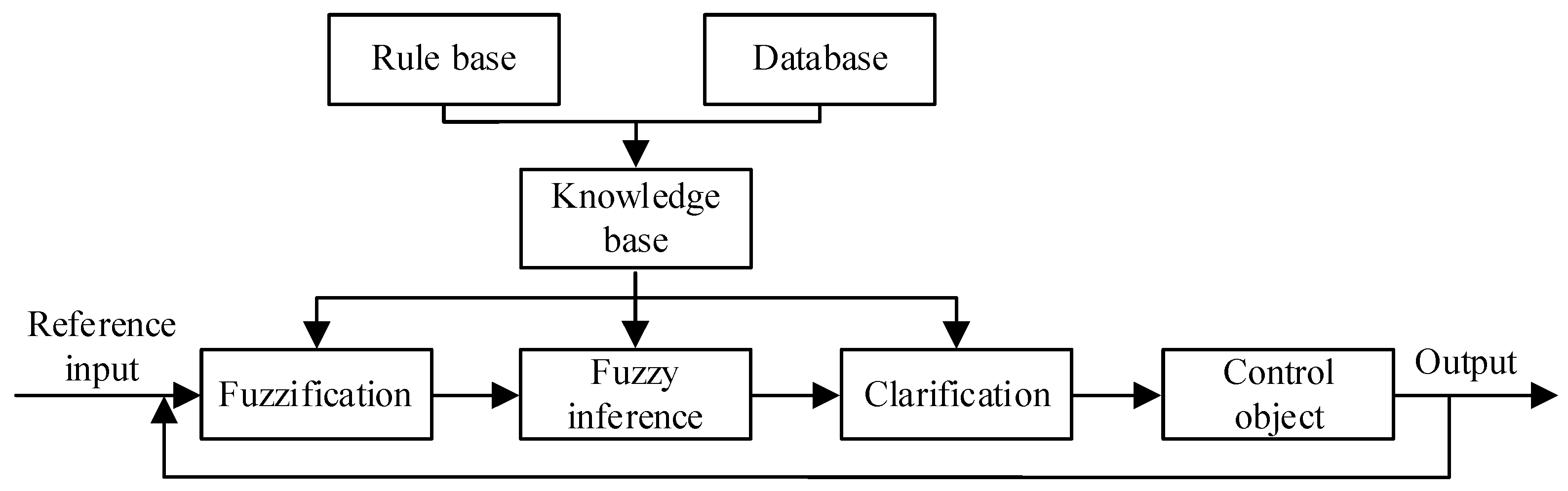
The basic structure of the fuzzy controller is shown in
Figure 3.
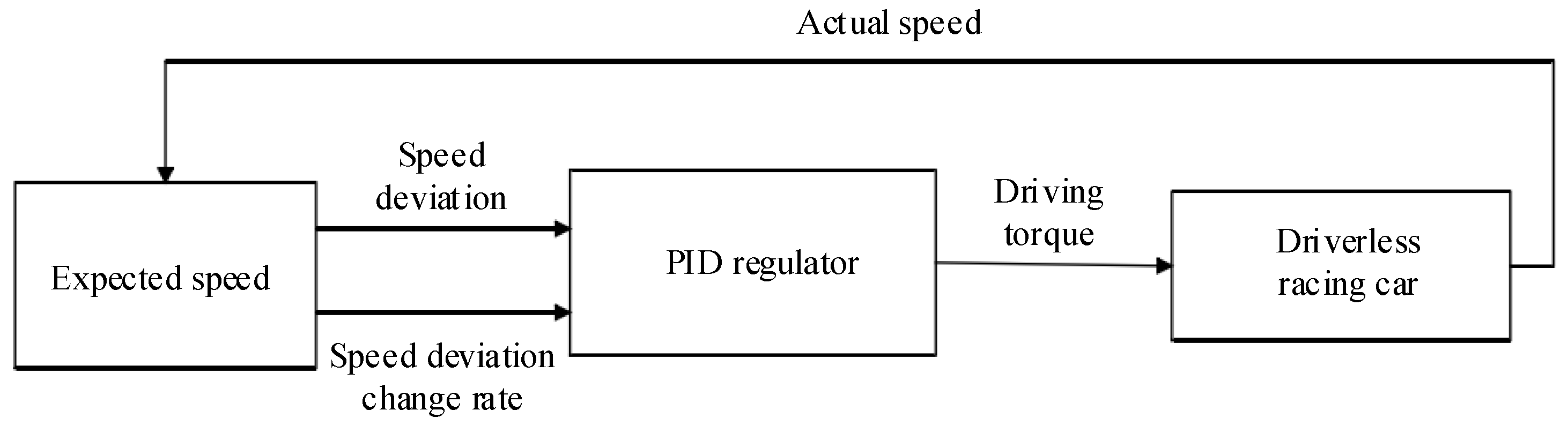
2.4. Longitudinal Controller of Racing Car Based on Incremental PID
In essence, the UEFC’s longitudinal control is a speed control system, which aims to track the expected speed through the control of acceleration and deceleration. In accordance with deviation between the vehicle’s expected speed and its actual speed, the main control principle of longitudinal control is to obtain the ideal acceleration and deceleration control quantity. Then, it must be input into the corresponding controller for execution. The longitudinal control of racing car includes the switching control of acceleration control system, braking control system and acceleration and deceleration system. Therefore, this research introduces the incremental PID control method, which is a basic form of digital PID control algorithm and a control algorithm for PID control. This can be achieved through the increment of control quantity (the difference between the current control quantity and the last control quantity). The longitudinal control structure of racing car on the basis of incremental PID is presented in
Figure 4 [
19].
The longitudinal control of the driverless car is mainly the control of car’s longitudinal axis direction. It generally includes the control of the car’s displacement, longitudinal speed and acceleration. When the car is running on a straight track, it needs to increase its speed and decelerate before entering the curve. Therefore, in order to make the car complete the race quickly and stably, it needs to adjust the longitudinal speed in real time according to the track conditions. As a nonlinear system, driverless car brings many difficulties to the design of longitudinal controller, and it is difficult to ensure its control accuracy and robustness. The longitudinal control principle of the driverless car is to control and adjust the torque of the driving system in real time. At the same time, it should indirectly control the speed and acceleration of the car, and realize the tracking and control of the expected speed of the driverless car.
PID control, which is a classical control technology in modern control, has advantages including simple structure, reliable operation, good stability, convenient parameter adjustment and so on. In accordance with deviation of the controlled system, PID control combines the integral coefficient I, proportional coefficient Pas well as differential coefficient D linearly to control the controlled object.
and
are used to represent the expected output and actual output, respectively. The calculation formula of PID control algorithm is shown as follows:
In the formula, refers to the proportional adjustment coefficient; refers to the integral adjustment coefficient; refers to the differential time constant.
The proportional regulation coefficient
in the PID control algorithm mainly regulates the system’s response speed, eliminates the error at the fastest speed, and makes the controlled quantity reach the expected value of the system [
20,
21]. The integral adjustment coefficient
is mainly to remove the steady-state error. The value of
corresponds to the speed of removing the system’s steady-state error. The differential adjustment coefficient
is mainly used to improve the system’s dynamic characteristics and keep the system deviation changing to the set point at all times.
The incremental PID controller has advantages including simple structure and small influence range on the system in case of failure. Additionally, the incremental PID control is selected as the control algorithm for the UEFC’s longitudinal control. The calculation formula of incremental PID controller is as follows:
In Formula (18), refers to the opening control increment of the electronic accelerator pedal; refers to the velocity deviation at the -th sampling; refers to the deviation between the expected speed and the actual speed. The incremental PID control takes the speed deviation input at the -th and -th sampling times as the independent variable. The incremental PID control compares the size, change direction and change frequency of the speed deviation during the last three sampling times. Additionally, the incremental PID control grasps the change trend of the UEFC’s speed at the next time. Through parameters , and , the system error is rapidly reduced so that the UEFC’s actual speed approaches the expected one, and finally reaches the target value stably.
Fuzzy PID adaptive controller is an intelligent algorithm that combines fuzzy control and PID control, and can adjust PID parameters online through empirical fuzzy rules. The input of the controller is error e and error change rate e
c. The fuzzy controller adjusts the changes of the three parameters of PID online according to the experience rules accumulated in the past [
22]. Then, the adjusted three changes
,
and
are added to the previously set initial value of the PID controller to obtain the final output, as shown in Equation (19).
Among them, , and are the initial parameters set by the PID controller, and , and are the transformation values set according to the fuzzy control rules. The characteristics of fuzzy controller can make up for the defects of traditional PID. It does not need to establish an accurate model of the controlled object, but only need to convert the previously accumulated experience into corresponding control rules for control. The fuzzy adaptive PID controller is more flexible, and usually has more obvious advantages for the object with large nonlinearity and time variation.
According to the difference between the expected and the actual speed as well as the difference change rate, fuzzy PI control is to correct the values of and so as to realize the purpose of online real-time adjustment of the proportional value P and integral value I. Therefore, the rule selection basis is as follows: when the speed error is large, select a larger value to obtain a larger driving torque value. When and values are moderate, select smaller and appropriate to obtain moderate driving torque. When is very small. In order to prevent over control of the speed, the value output is zero, that is, the fuzzy controller does not intervene.
2.5. Lateral and Longitudinal Controller of UEFC
When either the UEFC’s lateral control system or its longitudinal control system acts alone, UEFC cannot operate perfectly and the needs of various race tracks cannot be met. Due to the strong coupling relationship between the lateral and longitudinal control of the UEFC, a coordination controller is built to improve the lateral control effect. The coordination controller is built for combining the lateral control and longitudinal control to achieve the coordination control of the UEFC. The input parameter of the lateral control is the longitudinal speed, and that of the longitudinal control is the lateral position deviation. The lateral and longitudinal parameters are constrained by each other. In accordance with the analysis UEFC’s working conditions, the corresponding coordination law is established. In addition, the parameters are adjusted to achieve the lateral and longitudinal coordination control. The overall structure of lateral and longitudinal control of UEFC is shown in
Figure 5.
The coordination control of UEFC calculates the additional driving torque in accordance with actual position and lateral deviation of the racing car, and judges whether the racing car needs to accelerate or decelerate so as to realize the lateral and longitudinal coordination control of UEFC.
The longitudinal controller based on fuzzy PI is coupled. Through analyzing various working conditions of the car in the actual race, the lateral and longitudinal control laws are summarized, and the lateral and longitudinal control method of the driverless car is constructed. Compared with reference [
23], after the longitudinal control being added, the tracking effect of the car on the path was significantly improved. The car performs well in different curves, and the frequency and amplitude of the swing were also reduced a lot. This shows that the fuzzy PI adaptive controller is suitable for the longitudinal control of an unmanned car.
In case of a lateral position deviation, if the reference path is too far from the position, it should be properly decelerated to make the UEFC track the reference path under the action of lateral control. In case of a lateral position deviation between the reference path and the car, if the car approaches the reference path, it should be properly accelerated to make the car quickly track the reference path [
22,
23,
24]. The coordination control process of UEFC is as follows:
(1) It should judge whether the UEFC has a lateral deviation. Where the lateral deviation is more than a certain value , judge the angle. It is the included angle between the vehicle speed direction and the prediction range edge with the radius at the intersection of the reference path. is taken as the fixed axis. If the angle between vehicle speed and is formed by clockwise, the positioning is positive, while the counterclockwise is negative.
(2) It should determine which side the car is on. When the car is on the left side with regular and tends to be far away from the reference path, the car should reduce its speed, that is, reduce its driving torque. When the car is on the right side with regular and tends to approach the reference path, it should speed up, that is, increase its driving torque. When it is on the left side with negative , if the car tends to approach the reference path, it should speed up, that is, increase its driving torque. When it is on the right side with negative , if the car tends to approach the reference path, it should slow down, that is, reduce its driving torque.
represents the threshold for judging whether there is overlarge lateral deviation. In the case that the lateral deviation , it is deemed that the car has carried out tracking of the reference path and the control is not involved. In the case that the lateral deviation , it is deemed that the car lateral deviation to certain extent, and the controller should intervene for reducing the lateral deviation. The lateral deviation calculates an additional driving torque through the PID controller, and then judges whether the target driving torque needs to add or subtract the additional driving torque in accordance with coordination controller so as to finally realize the lateral control and longitudinal control.
3. Results
To verify the designed mechanical structure of the UEFC and the effectiveness of the coordination control method, the experimental analysis was conducted by the MATLAB/SIMULINK software. The coordinated control of the controller was carried out in Simulink. The parameters of the control model were coupled through the coordinated control module, so that the parameters in the joint controller were mutually constrained. The simulation model is the UEFC lateral and longitudinal coordination control model proposed in this study, and the basic parameters are as follows: the vehicle mass is 1620 kg; the distance from the mass center to the front axle is 1.35 m; the distance from the mass center to the rear axle is 1.43 m; the inertia moment is 2480 kg/m2; the wheel radius of the racing car is 0.355 m and the height of the mass center is 0.565 m.
The corner input of UEFC is shown in
Table 1.
In accordance with steering wheel input of UEFC in
Table 1, the angle for UEFC was input to check the coordination control performance of the proposed method.
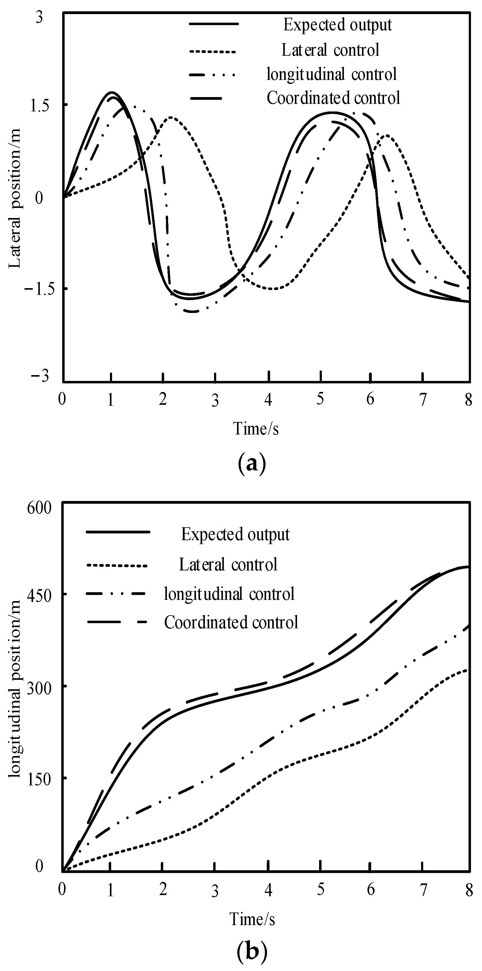
This method is used to coordinate and control the longitudinal and lateral control changes of UEFC when the vehicle is running. The vehicle coordinated control results of the proposed method were compared with those of UEFC under lateral control and longitudinal control. Among them, “Expected output” is the reference standard path. The lateral and longitudinal control tracking comparison results of the car are shown in
Figure 6.
In
Figure 6, the results of UEFC path tracking under different control modes are compared. Because the linear approximate expression of the tire is used in the process of simplifying the dynamic model, the side slip angle of the tire is also required to be limited so as to ensure that the force on the tire is in the linear region during driving.
In the lateral control, the output of the front wheel angle is controlled, and the steering motor drives the steering mechanism to achieve the change of the front wheel angle. Therefore, the limit position of the steering mechanism and the responsiveness of the steering motor need to be considered at the same time. The angle of front wheels turning from the middle position to the leftmost limit position and the rightmost limit position, as well as the turning angle of the steering motor, were obtained from the real vehicle test. It is defined that turning left is counterclockwise and the angle is negative, turning right is clockwise and the angle is positive and turning the steering motor 110° corresponds to a front wheel angle of 30°. The continuous working speed of the steering motor is 50 r/min, so when the front wheel rotates 30°, the steering motor works for 0.4 s.
According to the comparison results, the deviation between UEFC’s actual driving path and its reference path is large and swings unsteadily when under the lateral control only. Only when the UEFC’s speed is controlled longitudinally is the deviation reduced, but there is still a significant deviation. When the proposed method is used to coordinate and control the UEFC laterally and longitudinal control, the car can track the reference path well. In
Figure 5, further analysis of the experimental results shows that when only lateral control is adopted do the lateral position and longitudinal position of UEFC deviate greatly. During longitudinal control, the position deviation of the UEFC is maintained between the two control methods. When the proposed method is used for lateral control and longitudinal control of UEFC, the position deviation of UEFC is significantly reduced. The abovementioned experimental results indicate that the coordination control by this method can greatly cut down the path tracking deviation of UEFC.
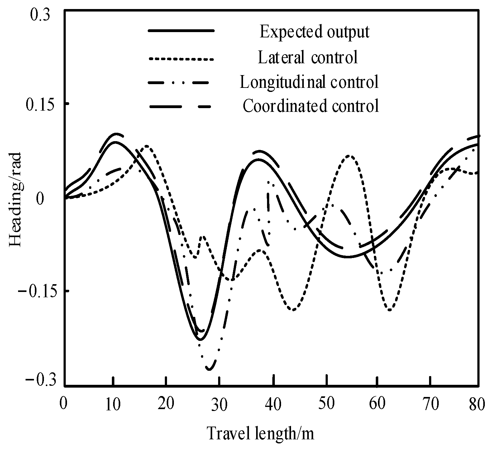
Three methods are used for the control of the UEFC’s heading angle. The results are shown in
Figure 7.
Figure 7 is a comparison of heading angle control results of UEFC under three control modes. When there is only lateral control, the course of the UEFC changes more frequently. It can be seen that the UEFC swings seriously when tracking the reference path. When the longitudinal control is adopted for the UEFC, the variation range of heading angle of the UEFC is significantly reduced. When the method in this paper is used for lateral control and longitudinal control of UEFC, the heading angle of UEFC can track the reference heading angle well, and UEFC can track the expected path of the experiment well.
Under the condition of constant speed, driverless racing cars can basically track the reference path through the control of the lateral controller, but there will be instability in the starting and turning places. The racing cars swing back and forth on both sides of the reference path. The swing amplitude and frequency vary at different speeds. When the speed is higher, the swing amplitude is greater. When the swing frequency is lower, the car’s actual heading angle can basically track the ideal heading angle. However, when the speed increases, the range of the racing car’s heading angle will increase. At the same time, the difference between the ideal heading angle and the racing car’s heading angle will become larger. By comparison, when the speed increases, the change frequency of the front wheel angle of the car increases. The lateral position can basically be maintained within the constraint range. There are some deficiencies in the lateral control of a given speed. It is necessary to control the longitudinal direction of the car accordingly to improve the control effect.
After longitudinal control is added and the lateral and longitudinal directions are decoupled, the car can track the reference path well. Additionally, the unstable situation is much less than that in
Section 3, where there is only lateral control. The course tracking error is reduced a lot; under the condition of longitudinal control, the lateral position deviation is maintained between −0.4 m and 0.3 m, which can be maintained within the comfortable distance defined in
Section 3. The deviation is smaller than that of only lateral control. With the participation of longitudinal control, the speed is adjusted accordingly under different path curvature. In order to achieve a better tracking effect, it is necessary to couple the lateral control with the longitudinal control.
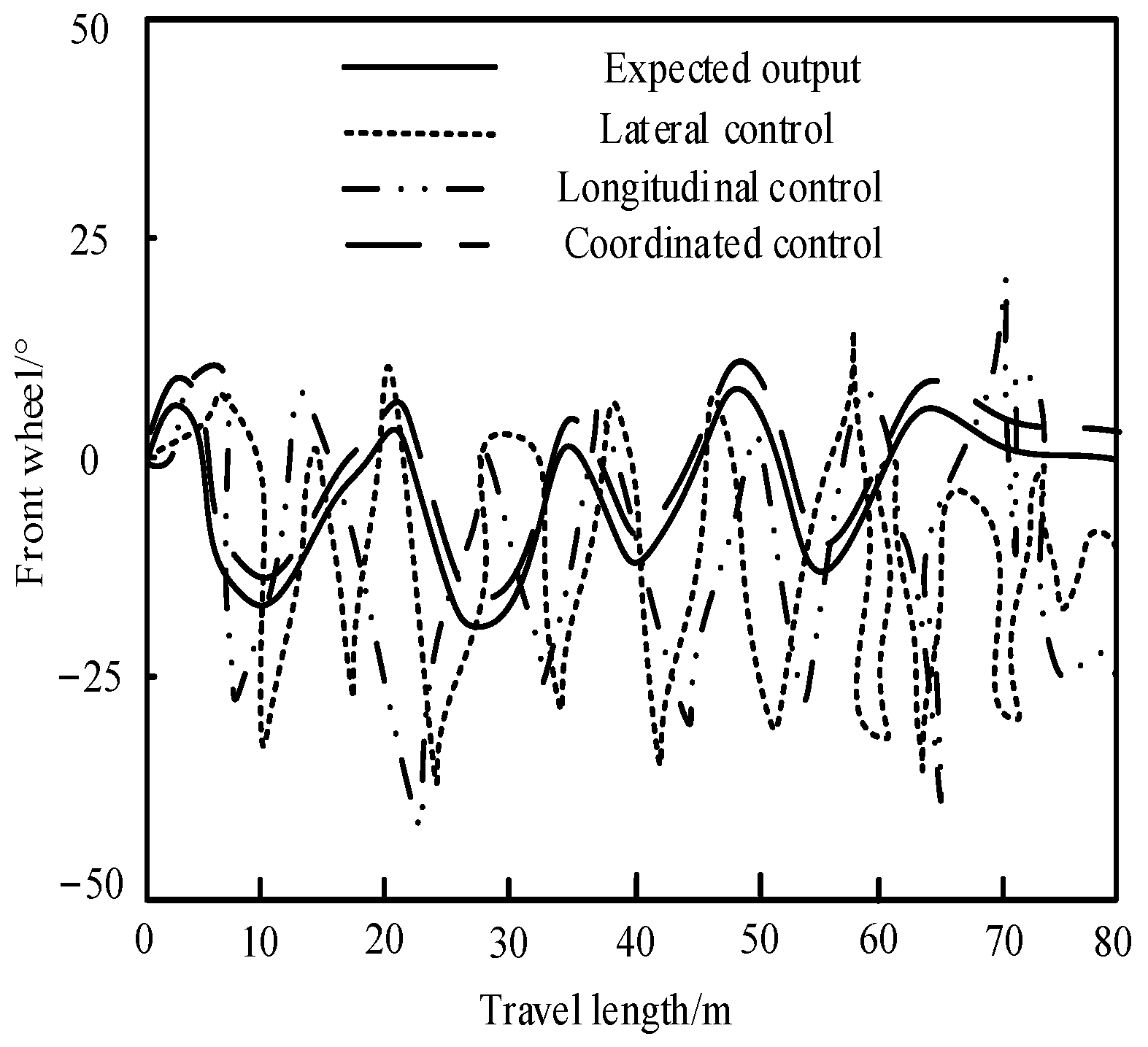
Three methods are used to control the front wheel angle of UEFC. The results are shown in
Figure 8.
The experimental results in
Figure 8 show that compared with the other two methods, the difference between the front wheel angle of the UEFC controlled by the proposed method and the expected output front wheel angle is small. In addition, the coordination control of UEFC can be realized using this method so as to keep the UEFC in an ideal running state. If the lateral control and longitudinal control are used alone, the change of the front wheel angle of the output is quite different from the expected output. The coordination control performance of the proposed method is significantly better than that under the lateral control and longitudinal control alone. The UEFC’s front wheel angle controlled by this method can control car steering in a favorable way, thus ensuring the car stability in path tracking.
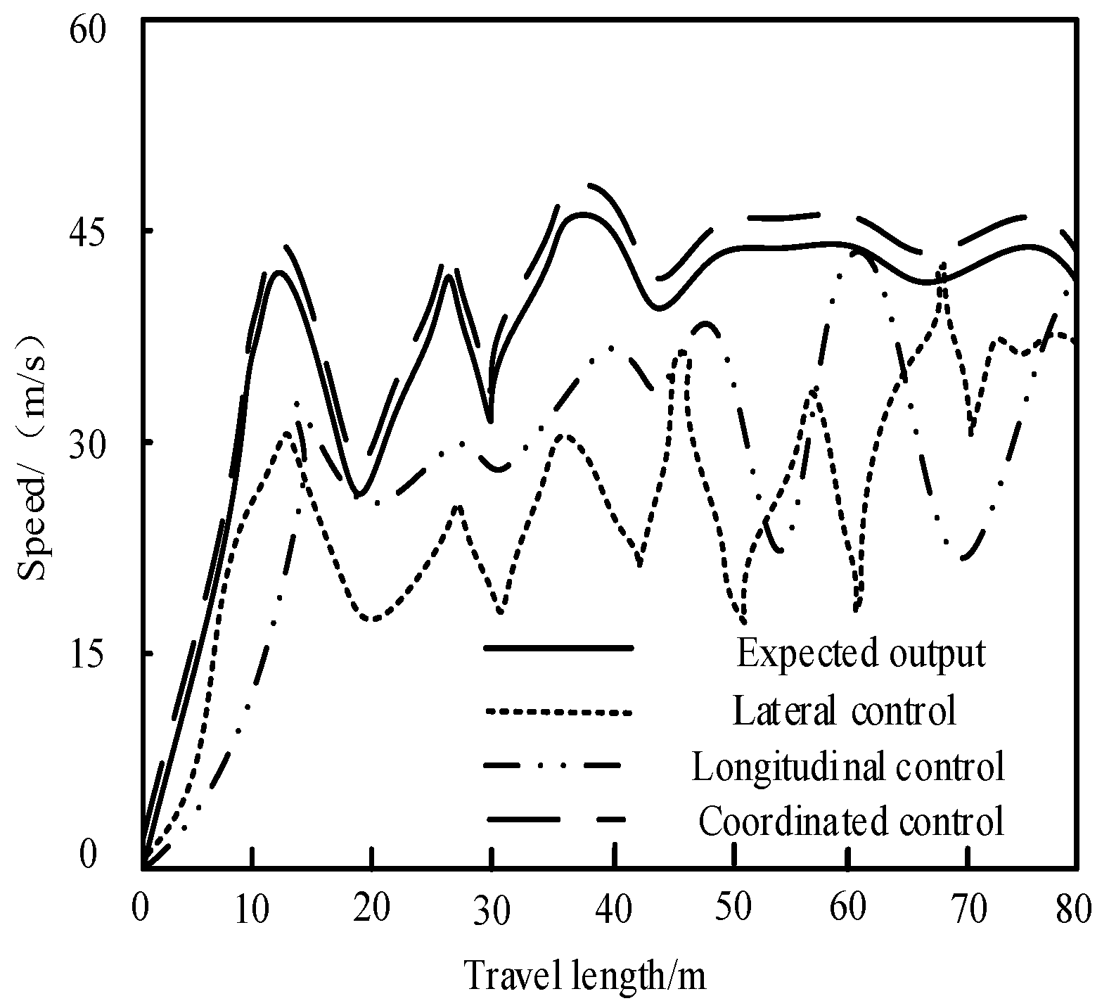
Three methods are used for the control of the UEFC’s speed. The results are shown in
Figure 9.
Figure 9 shows the speed tracking comparison diagram of UEFC under three control modes. When the lateral control or longitudinal control method is used alone to control the UEFC, the car speed is quite different from the expected output speed. When using the lateral or the longitudinal control of the proposed method alone to control the UEFC, the actual car speed is consistent with the reference car speed on the whole.
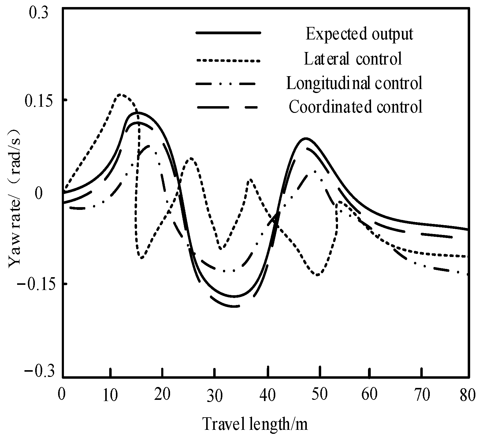
Three methods are used for the control of the UEFC’s yaw rate, and the control results are shown in
Figure 10.
The comparison of yaw rate control results of UEFC in
Figure 10 shows that the yaw rate of UEFC is very close using this method for coordination control of UEFC. It is verified that this method has coordination control performance and can ensure a yaw rate running within the expected range. To sum up, the coordination control method adopted in the proposed method has superior control performance for UEFC. This method can enhance the UEFC’s path tracking effect, which is feasible.
4. Discussion
This paper studied the coordination control method of UEFC, and realized the coordination control of the mechanical structure of UEFC through combining lateral control and longitudinal control of UEFC. Unmanned vehicle technology is the achievement of the highly intelligent development of modern vehicles. It brings together the technologies of multiple disciplines, such as network and communication, sensing and detection and electronics and control.
The simulation results showed that the car can basically track the reference path at different constant vehicle speeds. Although the lateral deviation increased slightly with the increase of vehicle speed, the car always followed the reference path under the action of the lateral controller. Additionally, it remained within the constraint range of trajectory tracking error, indicating the feasibility of model predictive control for lateral control. This study assumes conditions similar to the real road conditions. To test in this and verify the tracking performance of the lateral controller under variable speed conditions, the corresponding reference speed was set according to the curvature of the reference path. In order to ensure the real-time adjustment of the speed, a longitudinal controller based on fuzzy PI was designed. The simulation results showed that the car can adjust the speed and track the reference speed in real time according to the track conditions. At the same time, the feasibility of the lateral controller was demonstrated. When designing the lateral and longitudinal integrated control system, the lateral controller needs the vehicle speed as the input of racing state information. Additionally, the longitudinal controller needs the lateral deviation as the reference value, so the longitudinal speed and lateral deviation were taken as the coupling points of the lateral and longitudinal control system. At the same time, this study analyzed the actual multiple working conditions of the car and formulating the coordinated control law. The longitudinal controller based on fuzzy PI control strategy was coupled with the lateral controller based on model predictive control strategy. Through analyzing the various working conditions of the car in the actual competition process, the lateral control and longitudinal control laws were summarized, and the lateral and longitudinal control of the driverless car was constructed. By using Carsim and MATLAB/Simulink software, a joint simulation model was built. Additionally, the simulation test of longitudinal and lateral coordinated control was completed. The simulation results showed that under the role of the coordinated controller, the lateral tracking effect was significantly improved. There was no unstable swing state, the reference path could be tracked smoothly, and the lateral deviation remained within the set constraint range. The longitudinal speed control can track the reference speed and adjust it in real time according to the track and car status. Therefore, the lateral and longitudinal control proposed in this paper can eliminate the interaction between lateral and longitudinal control. This model can meet the requirements of lateral and longitudinal control, and conduct comprehensive control safely, stably and quickly so as to ensure the independent driving of the car.


