1. Introduction
Recent developments within the aerospace industry indicate that an increasing proportion of aerospace products will consist of cooperative platforms, in particular autonomous platforms such as aircraft, ships, missiles, drones and decoys.
Conventional radio communication between airborne platforms is usually implemented using antennas that radiate signal power omnidirectionally. A disadvantage associated with this approach is that the transmission power is not concentrated towards the receiver. This limits the communication range between nodes and increases power requirements, but more importantly, it simplifies node detection and positioning from an arbitrary location by an adversary.
This situation motivates a departure from omnidirectional transmission towards directed communication in order to obtain communication solutions with low probability of intercept/detection (LPI/LPD). Furthermore, if the receiver antennas are of digital multi-channel type, further advantages can be achieved, such as simultaneous reception at the same frequency, asynchronous or reactive reception and adaptive noise suppression [
1]. Thus, our approach assumes the use of directional antennas.
In addition, the use of mobile ad hoc networks (MANETs) would enable multihop communication bringing additional benefits, ranging from increased range of communication and robustness to network dynamics through the use of multiple paths between communicating nodes. However, in military heterogeneous environments involving airborne nodes, in terrestrial units, as well as in nodes at sea and in space, multihop routing suffers from several issues such as poor interoperability, heterogeneous software interfaces, non-standard link information reported by the involved radios and significant manual setup and configuration [
2].
It is crucial that the pilots of military aircraft have access to updated information about the location of friendly and hostile aircraft. This kind of information is provided through so-called situation awareness (SA) data. SA data contain, among other things, the location, direction and speed of friendly and hostile aircraft in an area.
We define the concept of the leaked packet. A leaked packet is a unit of data transmitted with a radio carrier wave that can be detected by an adversary aircraft. A packet is considered to be leaked even if the received radio signal to noise ratio (SNR) is so low that the adversary cannot receive and decode the data. Data on tactical links is typically encrypted, which makes decoding infeasible. However, it is enough that the adversary can discern the radio signal carrying the packet from electromagnetic noise. Adversaries can use this information to track the position of the transmitting aircraft.
In this paper, we present a routing protocol for airborne tactical networks. The protocol is called the Hostile-Direction Aware Routing Protocol (HDARP). The protocol requires nodes to be equipped with directional antennas and makes use of SA data to route packets from the sender to the receiver (including multi-hop routing when needed), while at the same time avoiding adversary detection/positioning by eliminating leaked packets. HDARP is intended to be used together with the widely adopted TCP/IP stack, with minor adaptions for directed communication. HDARP is protected by patent application SE 2200136-6.
3. Proposed Approach
3.1. Situation Awareness Data
A fundamental aspect of our proposed protocol is that we have access to data that are referred to as situation awareness (SA) data. Situation awareness is a critical component in military command and control operations, including flight missions in combat situations. In order to make real-time decisions about tactical maneuvers during a combat flight mission, the pilots must have good and accurate information about both adversary and friendly aircraft. SA data contain such information.
In our proposed solution, we work with a three-dimensional Euclidean space. The SA data consist of the following:
The x-position (longitude), y-position (latitude) and z-position (altitude) of each friendly aircraft in the current situation;
The speed in the x-, y-, and z-directions of each friendly aircraft in the current situation;
The acceleration in the x-, y-, and z-directions of each friendly aircraft in the current situation;
The x-, y-, and z-positions of each adversary aircraft in the current situation;
The speed in the x-, y-, and z-directions of each adversary aircraft in the current situation;
The acceleration in the x-, y-, and z-directions of each adversary aircraft in the current situation.
In some cases, the SA data only contain incomplete information regarding adversary aircraft position, usually the bearing (i.e., direction) from own aircraft location. This may be sufficient in our case, but otherwise the range (or distance) may be estimated with some uncertainty, e.g., by triangulation of a number of different observations.
In our work, a node has two sources of SA data. The first one is the set of SA sensors integrated with the airborne platform. The sensors have a maximum operational range, outside of which they cannot work reliably. We refer to the acquired sensor data as
local SA data. The union of all friendly nodes’ local SA data is the totality of environmental knowledge that friendly nodes pose as a group. We refer to this as a
unified SA view. It is important to keep in mind that although the unified SA view contains more data than available for a single node, it does not provide total SA visibility. Some nodes, friendly or otherwise, can be located so far away that they are not captured in the local SA data of any of the friendly nodes and are thus not available in the unified SA view. Each friendly node strives to obtain the unified SA view through exchange of SA data with friendly nodes. This is the second source of SA data. A node that receives SA data from another friendly node merges that with its own local SA and with previously received SA data from other nodes into something called the
node’s SA view. The merging operation favors local SA data over received SA data. In the ideal case, the node’s SA view becomes identical to the unified SA view. However, due to latency, packet loss and nodes out of range, a node’s SA view may diverge from the unified SA view. When this happens, it prevents the nodes from converging on a common topological view [
18]. This phenomenon can lead to subopotimal routing and strategies should be put in place to alleviate its effects.
The local SA data are updated regularly, and each SA datum has a timestamp. However, how often the SA data are updated is not completely defined. The SA data are used to keep track of where all aircraft are at each time. Accordingly, since the SA data are updated at certain intervals, the local aircraft needs to update the positions of the other aircraft in the interval to , where is the interval between updates/exchanges of the SA data.
Based on the SA data, we know the position of all friendly as well as adversary aircraft. In the next step, we can then calculate in which directions we can transmit using directional antennas in order to reach each aircraft directly, provided they are in range to receive the radio signal (Tx range). Further, we can also calculate whether other aircraft are reachable through intermediate friendly nodes, thus enabling a multi-hop routing protocol. The position of adversary aircraft allows us to determine if we would leak packets if transmitting towards a specific node. When using directional antennas, the radiation pattern will include a main lobe and a set of sidelobes. The region of 3D space where the signal can be detected, through the either main lobe or sidelobes, is referred to as a
forbidden sector, as described in
Section 3.4. HDARP avoids leaking packets by selecting routes outside forbidden sectors if such routes are available.
An important aspect of the topology control and routing scheme is that aircraft can both enter and leave a configuration. The enter/leave information should be present in the situation awareness data, thus enabling the routing information to be updated with new/disappearing nodes (aircraft).
3.2. Use Cases
One of the main advantages of a directional antenna is that it transmits only in a narrow angle, for example 10 degrees, which reduces the possibility of adversary detection. Therefore, we need to design a routing protocol that avoids transmitting in a direction where an adversary aircraft is located, which we call a forbidden direction. The forbidden direction is assumed to be aligned with the antenna boresight. By combining the forbidden direction with information about the shape of main lobe and sidelobes of radiation pattern one can specify the associated forbidden sector. The calculation of forbidden direction and sector and, thus, which aircraft we can communicate with in a single-hop, is an important part of the developed routing protocol.
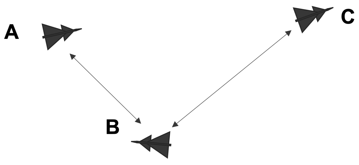
Figure 3 shows a use case where an adversary aircraft is in the neighborhood. In this case, when A wants to communicate with B, A is forced to use multi-hop via C in order to reach B without risk of being detected.
In order to describe the topology control and the routing protocol, we will start with the use cases below. In the evaluation of the protocol, we have more complex use cases (scenarios) as outlined in
Section 4.
3.3. Routing Protocol Description
Each node participating in the FANET runs an instance of the routing protocol described in Algorithms 1–4. It is assumed that each node is equipped with a mission computer (MC), which contains parameters pre-configured before the start of a mission. Examples of pre-configured parameters may include the node identification, identification of participants in the same squadron, MAC addresses assigned to network interfaces and corresponding IP addresses for all members of squadron, configured cryptographic services and associated cryptographic material, etc. This information is integrated into the node’s SA view.
When the routing protocol is started, it will begin the bootstrapping procedure described in Algorithm 1. The first step is to interface with the aircraft sensors and on-board auxiliary systems to identify any other nodes, friends or adversaries detectable in the range of the sensors. The information will include the position, velocity and acceleration of the discovered nodes, essentially yielding the node local SA data mentioned in
Section 3.1. The local SA data are inserted into the node’s SA view, which is an aggregation of SA data from local sensors and SA data obtained from other friendly nodes through routing protocol message exchanges. In bootstrap mode, no such exchanges have taken place yet, and therefore, the node’s SA view contains only local SA data. The third step is to call the
HDA_Routing procedure (Algorithm 4) to compute routes to any of the friendly nodes discovered. Finally, a timer called
send_SA_update is configured. When this timer expires, the node will share its SA view with other nodes located one hop away, which is the procedure outlined in Algorithm 2.
| Algorithm 1 Bootstrap at node n. |
| Require: Identity of node n running the bootstrap |
| 1: Use aircraft sensors to collect SA data (local_SA) |
| 2: Insert local_SA into SA_view |
| 3: HDA_Routing(SA_view, n) | ▹Executes Algorithm 4 |
| 4: Schedule send_SA_update timer | ▹Triggers Algorithm 2 when it expires |
Algorithm 2 is rather straightforward. When the
send_SA_update timer expires, this algorithm is invoked, and during its execution, it will prepare a message containing the node’s SA view and send it to the one-hop friendly neighbors. Information from the MC is not included in the updates, since it is assumed that each node has access to it from their own MC. After that, it will re-schedule the
send_SA_update timer for the next update to the neighbor nodes.
| Algorithm 2 Update neighbor nodes. |
| Require:SA_view, identity of node n running the algorithm |
| 1: procedure Send_SA_Update(SA_view, n) |
| 2: for each friendly node in SA_view reachable in one hop do |
| 3: Transmit SA_view to |
| 4: end for |
| 5: Schedule send_SA_update timer | ▹ Triggers this algorithm when it expires |
| 6: end procedure |
Algorithm 3 handles the situation when an SA view is received from a friendly neighbor. First, the node will update its local SA data by interfacing with the aircraft sensors and on-board auxiliary systems. If the new local SA data conflict with data in the node’s SA view, for example with SA data received earlier from a friendly node, the information from the local SA data will replace the existing data in the SA view. Our policy is that fresh local SA data are trusted above anything else. The currently received SA view,
recvd_SA_view, is merged into the node’s SA view using the same policy. Since SA data are timestamped, entries from the
recvd_SA_view will replace the node’s existing SA view data only if newer. The final step is to call the
HDA_Routing procedure (Algorithm 4) to re-compute routes that were affected by the received
recvd_SA_view message or changes in the node’s local SA data.
| Algorithm 3 SA fusion at node n. |
Require:SA_view, received SA_view from neighbor, node n running the algorithm
|
| ▹Triggered by message reception |
| 1: procedure Received_SA_Update(SA_view, recvd_SA_view, n) |
| 2: Use aircraft sensors to collect fresh SA data (local_SA) |
| 3: Merge local_SA into existing SA_view | ▹ local_SA data are preferred |
| 4: Merge recvd_SA_view into SA_view | ▹ local_SA data are preferred |
| 5: HDA_Routing(SA_view, n) | ▹ Executes Algorithm 4 |
| 6: end procedure |
The aim of the HDARP routing protocol described in Algorithm 4 is to exploit the information from the node’s SA view to determine the shortest paths from the node to all other friendly nodes, while avoiding forbidden sectors. The actual shortest-path computation is performed using an adaptation of Dijkstra’s shortest-path algorithm [
19] that produces a shortest-path tree. This approach is well known in computer networking, and therefore, rather than explaining it here, we point the interested reader to [
18,
20].
Dijkstra’s algorithm requires as input the source node for all the paths to be produced (denoted by n in the algorithm) and a weighted graph consisting of all vertices and directed edges in the graph, which in our case correspond to nodes and links. When directed edges are used in a graph, the edge is distinct from .
The first step in Algorithm 4 is to collect all friendly nodes from the SA view into the set . Secondly, we create an empty set that will eventually be populated with links connecting a pair of nodes. We cannot add the links yet because we need to determine a) which pairs of nodes are connected by a link and b) the weight (cost) assigned to that link. Two nodes, u and v, will be connected by a link if node v is in Tx range from u. In addition, if node u is in Tx range from v, there will be an additional link . The weight of a link is determined by whether or not the link connecting the two nodes overlaps with a forbidden sector. To enable this determination, we collect all adversary nodes from the SA view into the set .
The algorithm iterates through each node
in
and creates an outgoing link to each of the remaining
nodes that can be be connected to it according to (
a) and (
b). If a link was created, the algorithm will iterate through each adversary node
a in
to test if it causes a forbidden sector for the new link. The forbidden sector detection is performed as described in
Section 3.4. Links outside a forbidden sector are assigned unit cost, whereas links inside a forbidden sector are penalized with a high cost. The link can be excluded from the topology instead of increasing its cost if the mission requires radio silence. The costs along a path are additive. Dijkstra’s algorithm will attempt to minimize the total cost of a path towards a specific destination.
In a network with n nodes, the longest possible acyclic path consists of links. If all links are outside forbidden sectors, the cost for such a path is considering the unit link cost as mentioned above. Thus, the lowest penalty cost that can be chosen for links inside forbidden sectors is n, the number of nodes in the network. A path consisting of one or more such links will have a cost that exceeds the cost of any acyclic path where all links are outside forbidden sectors. In our simulations, the nodes forward IPv4 packets. The time-to-live (TTL) field in the IPv4 header is 8-bit wide, limiting the longest path to 255 links. Therefore, the lowest penalty cost for IPv4 links is 256. In our case, we have set the cost of links located in forbidden sectors to 5000. This value does not confer any advantage or disadvantage compared with 256, but is rarely occurring in the simulations and is thus easy to find in the log files.
In the final part of Algorithm 4, the shortest-path tree produced by Dijkstra’s algorithm will be used to update the IPv4 routing tables of node
n.
| Algorithm 4 Hostile-Direction Aware Routing (HDARP) at node n. |
Require:SA_view, node n running the algorithm
- 1:
procedure HDA_Routing(SA_view, n) - 2:
Group friendly nodes from SA_view in a set - 3:
Create an empty set that will store links between friendly nodes - 4:
Group remaining nodes from SA_view in a set - 5:
Use the sets and to define a directed topology graph - 6:
for each node do - 7:
for each node other then do - 8:
if in Tx range from then - 9:
Add the directed link to set - 10:
Set link cost: .weight - 11:
else - 12:
continue - 13:
end if - 14:
Is_Forbidden_Sector(, , ) - 15:
if f = True then - 16:
Set link cost: .weight - 17:
break - 18:
end if - 19:
end for - 20:
end for - 21:
Dijkstra(n, ) ▹Shortest paths from n to other nodes in - 22:
Use to update the IPv4 routing table entries at n - 23:
end procedure
|
3.4. Forbidden Sector Detection
The goal of the forbidden sector detection method is to determine if an adversary aircraft can detect the communication between two friendly nodes. More specifically, it is to determine if the adversary is able to distinguish the main lobe or sidelobes of the incoming signal from electromagnetic noise. To do so, we construct a 3D geometrical model (i.e., a 3D volume) of the radiation pattern, main lobe and sidelobes combined and determine if any of the adversary aircraft are located within the volume. If any such adversaries are found, then the sending node should avoid direct communication and instead try to forward the packet through other friendly nodes unaffected by forbidden sectors.
We have used a tetrahedron as a first-order approximation of the radiation pattern, as shown in
Figure 4. This provides us with an acceptable tradeoff between accuracy and computation time: the last one being particularly important for reducing simulation time. The tetrahedron is created such that the sender is at the center of the tetrahedron base, and the receiver, Blue 2, is located at the apex of the main lobe. Obviously, this assumes that the receiver is within Tx range from the sender; otherwise, direct communication is not possible. In addition, we assume that when the receiver is located closer than Tx range, the sender can adjust the transmission power so the SNR for received signal is just enough for the sender to decode the data. This reduces the likelihood of leaking data behind the receiver. However, according to information from our aerospace industry partner, the receiver can decode the incoming signal (with an acceptable BER) if its SNR is at least 10 dB. Furthermore, given that a signal can be
detected if it is just above the noise floor, when this information is plugged into a simplified path loss model [
21], the outcome indicates that a signal can be discerned as far as three times the distance from sender to receiver along antenna boresight. Therefore, we extend the tetrahedron apex at three times the distance from the sender and receiver, which is the
detection range, the maximum distance at which an adversary can detect the transmission. Similarly, we extend the radius of the tetrahedron base (i.e., the distance from center to each of the three vertices) to
of the detection range to prevent detection through the sidelobes. Thus, our forbidden sector detector consists of the tetrahedron constructed as described above combined with logic to detect if any adversary is located with the 3D space of the tetrahedron.
It is important to point out that when the transmission power is adjusted for the distance to the receiver, the volume of 3D space used by main and side lobes of the signal will change accordingly. Similarly, the tetrahedron is scaled proportionally to the distance to the receiver, but the aspect will remain the same.
The left part of
Figure 4 illustrates the operation of the detector in the scenario where node Blue 1 wants to transmit to node Blue 2. The red and green nodes are hostile nodes that should not be able to detect the transmission. The right part of
Figure 4 represents a cross-section of the figure on the left, as seen from above, and is rotated so that the tetrahedron apex points upwards. The figure also shows the embedded radiation pattern (also a cross-section of the 3D pattern). The Green node is outside the tetrahedron and thus does not pose a detection risk. However, node Red 1 is able to detect the signal from the sidelobes. In addition, although the signal that passes Blue 2 has a very low SNR, it is also detectable by Red 2. Thus, the location of either Red 1 or Red 2 is enough reason to conclude that the transmission from Blue 1 to Blue 2 is located inside a forbidden sector and that an alternative path through an intermediate friendly node would be preferred.
The logic used to detect if an adversary is inside the tetrahedron is captured by Algorithms 5–7. The algorithms presented here are based to a large extent on discussions available online [
22]. Algorithm 5 constructs a tetrahedron with the apex oriented towards the destination node and with the sender node located at the center of the base. We use the convention that
T.v1,
T.v2 and
T.v3 are the coordinates for the three vertices defining the base of the tetrahedron
T. The position of the tetrahedron apex (forth vertex) is available in
T.v4.
| Algorithm 5 Forbidden sector detection. |
Require: sender, receiver, set of adversary nodes
- 1:
procedure Is_Forbidden_Sector(src, dst, ) - 2:
Tetrahedron(src.pos, dst.pos) - 3:
for each node do - 4:
if IsInside(T, a) = True then - 5:
return True - 6:
end if - 7:
end for - 8:
return False - 9:
end procedure
|
The attribute pos appearing to the right of a node variable (e.g., src and dst) contains the 3D coordinates of that node. The algorithms iterates through all adversary nodes, calling the IsInside procedure (Algorithm 6) to check if any generate a forbidden sector. In that case, the algorithm aborts and returns True. Otherwise, if none of the adversaries are located within the tetrahedron space, the algorithm returns False.
Algorithm 6 checks for each of the four planes making up the tetrahedron if the opposite vertex and the adversary node are located on the same side of the plane. If this is true for all planes, it means that the position of the adversary is a point located inside the tetrahedron. Otherwise, the adversary is on the outside.
| Algorithm 6 Check if adversary is within tetrahedron. |
Require: tetrahedron, adversary node
- 1:
procedure Is_Inside(T, a) - 2:
Is_On_Same_Plane_Side(T.v1, T.v2, T.v3, T.v4, a.pos) - 3:
Is_On_Same_Plane_Side(T.v2, T.v3, T.v4, T.v1, a.pos) - 4:
Is_On_Same_Plane_Side(T.v3, T.v4, T.v1, T.v2, a.pos) - 5:
Is_On_Same_Plane_Side(T.v4, T.v1, T.v2, T.v3, a.pos) - 6:
if = True and = True and = True and = True then - 7:
return True - 8:
else - 9:
return False - 10:
end if - 11:
end procedure
|
The logic to detect if the opposite vertex and the adversary are located on the same side of a plane is shown in Algorithm 7. The first three input parameters,
,
and
, are the coordinates of the vertices defining the plane. Vertex
is used as common origin when using the coordinates to construct two vectors,
and
, that span the plane. The cross-product
of these two vectors is perpendicular to the two vectors spanning the plane, and is thus a normal to the plane. Similarly, we use the remaining two parameters
and
to construct two vectors
and
, using the same origin
as before. The normal
is then used as a reference direction when computing the dot products of the normal with these two vectors. The dot product returns a positive value if the angle
between the vector and normal is
and it returns a negative value when
. When the vector and normal are perpendicular their dot product is zero. Therefore, if both dot products,
and
, have the same sign, it means that
and
are on the same side of the plane. When both dot products are zero, it means that the two vectors are on the plane. In this situation, we still claim the two vectors are on the same side as this weighs towards concluding that the adversary is within the tetrahedron space (pessimistic view). The
Sign function shown in Algorithm 7 returns integer −1 if the numeric argument is negative, +1 if positive, and 0 otherwise.
| Algorithm 7 Check if opposite vertex and adversary are on the same side of the tetrahedron plane. |
Require: Tetrahedron plane vertices, opposite vertex, adversary position
- 1:
procedure Is_On_Same_Plane_Side(, , , , ) - 2:
Compute normal to the plane spawned by and : - 3:
▹ Cross-product - 4:
Compute dot products between plane normal and vectors towards and : - 5:
- 6:
- 7:
if Sign() = Sign() then - 8:
return True - 9:
else - 10:
return False - 11:
end if - 12:
end procedure
|
4. Methodology
We have used the OMNEST simulator framework to evaluate HDARP. OMNEST is the commercial version of the well-known simulator framework OMNeT++ [
23,
24]. OMNEST uses a modular, component-based approach to build simulations. At the core, OMNEST modules are written in C++, but at a higher level, they can be combined and extended using OMNEST’s Network Description (NED) language. We also made use of the INETMANET [
25] open-source model library, which contains models for the internet stack, wired and wireless link-layer protocols and more. Historically, INETMANET was forked from the official INET [
26] model library in order to address the shortage of MANET protocol components. Nowadays, INET and INETMANET are pretty much aligned in terms of functionality and compatibility with each other. However, INETMANET continues to provide access to additional MANET protocols, which is the reason we preferred it for our study. INETMANET does not have specific versioned releases. The code we use in our simulations comes from Git commit
6708b98344e5fd5a5e788da97367efa9150629a2. Both INET and INETMANET are well described in [
27].
We have compared HDARP’s performance against five other MANET protocols available in INETMANET: AODV [
28], BATMAN [
29], DSDV [
30], DSR-UU [
31], and OLSR [
32], respectively. Initially, we included additional MANET routing protocols from INETMANET, AODV-UU [
33], Dymo [
34,
35] and Dymo-FAU [
36], but these crashed multiple times during our simulations and are therefore not included in the results. Notably, DSR-UU and AODV-UU are protocol implementations for the Linux kernel that later were also made operable with the ns-2 and OMNeT++ simulators.
For all nodes that are simulated, we used the NED language to inherit generic networking functionality from the AdHocHost component, which provides among other things a TCP/IP stack simulation model, support for mobility models, a loopback interface as well as a wireless interface. In addition, the nodes were configured to use one specific MANET routing protocol from the selection above, including our own HDARP routing protocol.
Every node derived from the AdHocHost component can be equipped with an arbitrary number of applications. These simulation modules exploit functionality of the underlying TCP/IP stack to communicate with peer modules application located on other nodes, typically using a socket abstraction. However, the applications can also subscribe for signals from lower layers and other modules, or hook into the functionality of the underlying TCP/IP stack to provide special processing for incoming and outgoing packets, much like the functionality of the Linux netfilter [
37]. In our case, we equipped the nodes in the simulation with two applications, InterceptApp and UdpBasicApp, described in
Section 4.1 and
Section 4.2, respectively.
The nodes were also equipped with a mobility model that imports realistic flight path traces provided by our aerospace industry partner. This module was implemented using a combination of C++ and NED. Our mobility model reads data from file where records are indexed by monotonically increasing timestamps. Each record contains the 3D position of a specific node at the time indicated by the timestamp. The module computes instantaneous node velocity and acceleration using the data from the records. In addition, the module interpolates the position of the aircraft between two consecutive timestamps using the computed velocity. The module emits a notification each time a node updates its position, either through interpolation or by advancing to the next record in the data. It is important to note that each node participating in the simulation is equipped with its own mobility model instance that emits notifications for that particular node.
HDARP nodes are configured as above with the notable exception that they require an additional SA module to implement situation awareness. Every HDARP node has its own SA module instance that subscribes to mobility notifications from all nodes in the simulation. The mobility data are used to update the node’s SA view. The SA module has logic to determine if specific nodes are “visible” based on sensor range, which is a configurable parameter. Invisible nodes are excluded from the node’s SA view computed by the module. The same procedure is applied when receiving SA updates from friendly nodes.
The HDARP routing module receives a notification from the SA module every time the SA view is updated. For each notification, it determines whether routes must be recomputed as described in
Section 3.3 above. To avoid stale routes, the HDARP module purges the existing routes in the IPv4 routing table before installing routes derived from the current SA view.
Unfortunately, there is almost no support for antenna arrays components with beamforming in INET/INETMANET, with the notable exception of [
38]. Furthermore, our interest was primarily in the behavior of the routing protocol, separated from the intricacies of the link layer and physical layer models. Consequently, we made a pragmatic simplification by configuring the wireless interface to use the AckingWirelessInterface module. This module contains two submodules: a unit disk radio (UnitDiskRadio) and a very simple MAC protocol (AckingMac).
The unit disk radio is configured to perform interference modeling, which means that when a node transmits a MAC frame, all nodes within Tx range will be able to receive the frame, unless other nodes within Tx range are transmitting at the same time, in which case the reception will fail. The model implies the use of a isotropic antenna, which is at odds with our aim to use directional antennas. Instead, we emulate the effects of a directional antenna through the InterceptApp module, which is presented in
Section 4.1.
The AckingMac is trivial in the sense that it offers encapsulation and decapsulation of link layer frames, but no medium access procedure or retransmission.
For over-the-air tactical links, it is common practice to avoid the use of the Address Resolution Protocol (ARP) [
39] in order to reduce latency. Instead, IP addresses are mapped to MAC addresses in a static table available as a parameter in the MC, or the mapping is a deterministic function based on the assigned IP address of a node. We have configured the simulator to use GlobalArp in order to avoid ARP exchanges. The GlobalArp is a lookup table of IP to MAC address mappings available to all simulation nodes.
4.1. InterceptApp
The InterceptApp provides three services: it emulates the functionality of directional antennas for nodes derived from the AdHocHost component, it provides the means to measure the number of leaked packets by such nodes, and it helps implementing teams/groups (e.g., red, blue, green) while running a separate MANET for each team. To provide these services, InterceptApp uses a subset of the SA functionality from the SA module described above.
The application subscribes to notifications from the MAC layer about incoming packets received by the wireless network interface. Each notification provides access to the full packet, including the MAC headers. The InterceptApp extracts the source MAC address and the destination MAC address from the packet headers and uses these to look up the identification of the sender and receiver in the node’s SA view. If the sender does not belong to the same team as the node that received the packet (i.e., the node where InterceptApp is currently executing) and directional antenna emulation is turned off, then InterceptApp will record the incoming packet as a leaked packet.
In the case when directional antenna emulation is enabled, the receiving node will run Algorithm 5 with sender and receiver identities as input for the first two parameters. The third parameter, the set , will contain a single element, which is the identity of the node that received the packet. In essence, the algorithm answers the following question: would this node have received the packet if the sender from the other team instead of isotropic antennas used directional antennas with a radiation pattern following the tetrahedron model? If the answer is yes, the received packet would be leaked even if directional antennas were in use, and thus, the packet is marked as leaked.
In either case (directional antenna emulation on or off), the application will force the TCP/IP stack to drop the packet if the sender belongs to a different team. Existing MANET protocol modules in INET/INETMANET are not aware of the concept of a team. Without InterceptApp, they will try and succeed to use nodes from other teams as relay nodes.
If the sender belongs to the same team, normal packet processing will ensue.
4.2. UdpBasicApp
As described above, all nodes in the simulation are equipped with an application called UdpBasicApp. The application can send UDP datagrams to a set of preconfigured IP addresses and port numbers. The datagram size and the send rate can be configured either as fixed values, or as random values drawn from a specific probability distribution. In addition, UdpBasicApp listens on a configurable port for incoming UDP datagrams and uses these to compute basic statistics for metrics such as throughput and packet lifetime.
We have configured UdpBasicApp to draw the datagram size from a discrete uniform distribution over the interval 100 bytes to 1000 bytes. Similarly, the datagram send rate follows a discrete uniform distribution over the interval 100 ms to 200 ms. This is intended as a rough approximation of low bitrate voice-over-IP communication between the planes, such as that produced by the Mixed Excitation Linear Prediction Enhanced (MELPe) codec, including real-time transport protocol (RTP/RTCP) headers [
40,
41]. Each node in the simulation is configured to send UdpBasicApp datagrams only to all other nodes belonging to the same team, but none to nodes belonging to other teams.
The random numbers are generated using an implementation of the Mersenne Twister [
42] pseudo-random number generator (PRNG) that is included in the OMNEST distribution. In OMNEST, multiple PRNG instances can run simultaneously to create independent streams of random numbers. We have dedicated a PRNG instance to the UdpBasicApp. This way, the random events in UdpBasicApp are not affected by random events in the reminder of the simulator (e.g., scheduled updates in the routing protocol that include a random delay component). The result is that the transmission time and size for UdpBasicApp datagrams remain the same when we change the routing protocol. In effect, this becomes the workload against which we evaluate the MANET protocols in this study.
4.3. Simulation Scenarios
In our evaluation of the protocols, we will use two different simulation scenarios:
Scenario 1: R4B4, which contains four red aircraft and four blue aircraft representing two different teams (red and blue). This scenario is depicted to the left in
Figure 5.
Scenario 2: BVR (beyond visual range), which contains a total of 24 aircraft from three teams (red, blue, green). This scenario is depicted to the right in
Figure 5.
In Scenario 1, the two teams start far enough from each other to avoid leaking packets to the adversary, but close enough (i.e., within Tx range) within the team to enable direct communication. The two teams approach each other until the majority of the nodes are in detection range from at least one of the adversary aircraft. At this point, HDARP starts using multi-hop communication to avoid forbidden sectors. Eventually, the aircraft veer away from adversary nodes.
In Scenario 2, the red and blue team consist each of a bulk of eight fighter jets. These are shown closely packed together, visible as clusters in the figure. We have drawn a vertical red line in that figure that separates the two clusters. In addition, the red and blue teams have each two airborne early warning (AEW) nodes that act as command-and-control (C2) centers from behind the fighter jets. They are shown to the far left and right of the figure, respectively. Furthermore, the blue team has a node denoted as blue-ship1, visible at the top of the figure on the left side of the red vertical line. Similarly, the red team has a red-ship1 node located at the bottom, on the right side of the red vertical line. Blue-ship1 and red-ship play the role of mid-air tanker aircraft. The green team has two nodes, one at the top on the right of the vertical line and one at the bottom on left of the vertical line. We have drawn arrows in the figure to ease the identification of the green nodes in the figure.
The red and blue clusters are initially out of Tx range from each other, and thus, direct communication within the cluster is possible. The clusters approach each other while the AEW nodes remain behind. The tanker aircraft remain stationary through the whole simulation. When the two clusters come within Tx range, they begin using the tanker and AEW nodes in their team as relay nodes. The green nodes are out of Tx range for the entire simulation, and thus, cannot communicate with each other. Their role is to stress the directional antenna emulation part of the simulation, as well as the forbidden sector detection in HDARP. After a close encounter, the red and blue clusters return to their approximate starting positions.
In each scenario, we can choose one out of six routing protocols: AODV, BATMAN, DSDV, DSR-UU, HDARP (our protocol), and OLSR, respectively. A third parameter is the antenna type: directional (dir), or omnidirectional (omni). The choice of antenna only affects the operation of InterceptApp, but the simulation must be re-run if we want results for a different antenna type. To increase the statistical accuracy of the results, we run each scenario + protocol + antennna type combination 30 times with different RNG seeds.
4.4. Simulation Settings
In
Table 1, we list the critical simulation parameters used to produce the results in this study. In the case where multiple parameter values were simulated, the distinct values are separated by comma in the Settings column. For the remainder of simulation components, including MANET protocols others then HDARP, we have used the configured default settings in OMNEST/INETMANET.
5. Results
As discussed previously, it is important that no packets are leaked to hostile aircraft. If traditional omnidirectional antennas are used, there is a very high risk that a packet is leaked. This risk is reduced if directional antennas are used. However, even when using directional antennas, there is still a risk that a packet is leaked if there are adversary aircraft close to the sender or the receiver (see
Figure 4). The main benefit of the HDARP protocol is that it considers forbidden sectors so that the risk for leaked packets is substantially reduced.
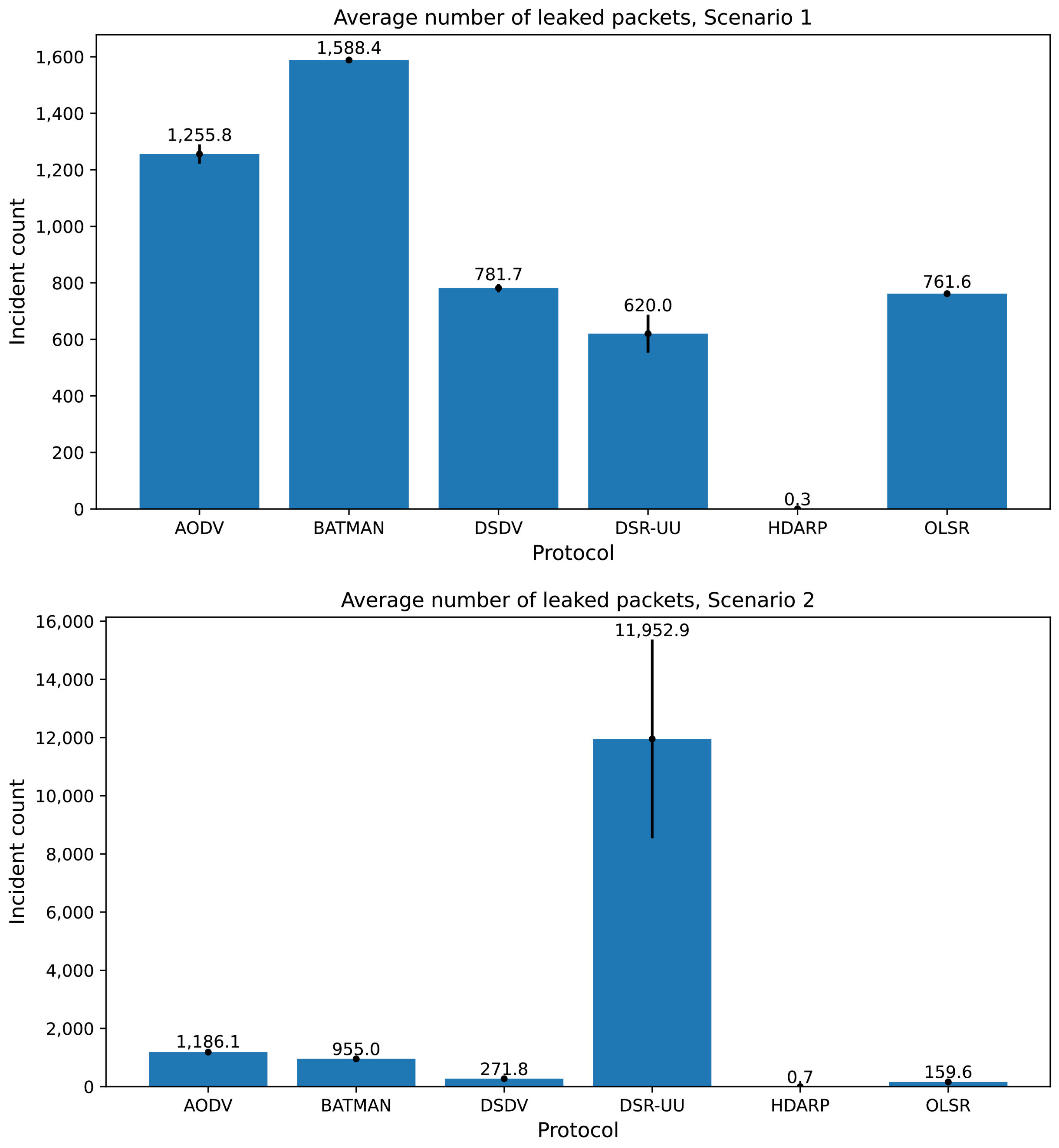
Table 2 and
Table 3 show the reduction of leaked packets when using directional antennas instead of omnidirectional antennas for the five protocols, which the HDARP protocol is compared to for scenarios 1 (R4B4) and 2 (BVR). The table shows that using directional antennas reduced the number of leaked packets with a factor 133 to 222 (depending on the protocol) for Scenario 1 and with a factor of 110 to 7464 for Scenario 2. This means that the reduction of leaked messages due to using directional antennas is very high. However, some packets are still leaked to an adversary aircraft.
Figure 6 shows the number of packets that are leaked when using directional antennas. The averages and the 99% confidence intervals are shown in the figure. The confidence intervals are very small with the exception of DSR-UU that has a somewhat larger confidence interval than the other protocols. DSR-UU is a complete protocol implementation for the Linux operating system that was later integrated with OMNEST, unlike the other protocols, which are pure simulation implementations. However, it is difficult to assess whether this is the reason for the large confidence intervals observed without an in-depth code review, which is outside the scope of this study. The figure shows that the HDARP protocol has (virtually) no leaked packets, whereas the other protocols have a substantial number of leaked packets for the scenarios considered here.
In order not to leak packets, the HDARP protocol sometimes avoids sending packets directly from the sender to the destination, since such direct transmissions could be detected by adversary aircraft (see
Figure 3 and
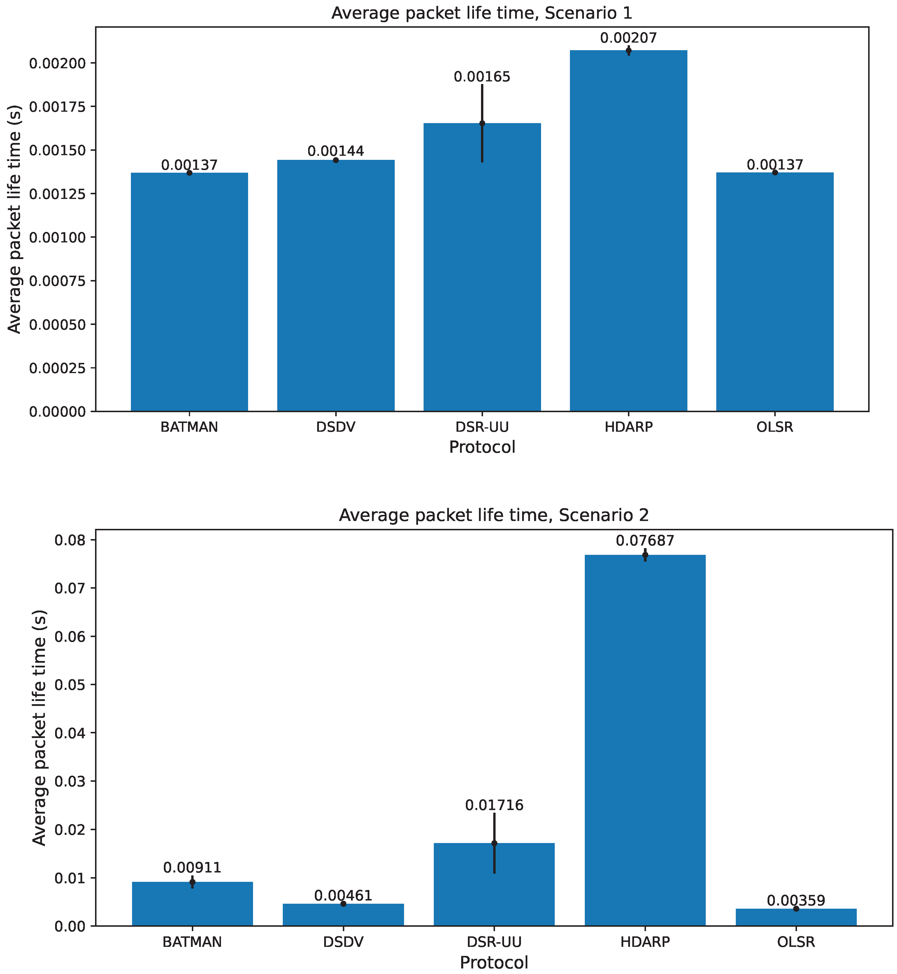
Figure 4). This means that one would expect that the number of hops and, as a consequence of this, the average end-to-end packet delivery time of HDARP could increase compared to protocols that do not consider forbidden sectors. Packet delivery time includes queuing time in each node on the path, as well as transmission and propagation delay for each link of the path.
Figure 7 shows that average packet lifetime of the HDARP protocol is longer than the average packet lifetime for four of the other protocols. The difference is small for Scenario 1, but rather significant for Scenario 2. In practice, the type of traffic routed by HDARP will consist mostly of voice-over-IP communication. Conventional wisdom indicates that for this type of traffic, the one-way latency should not exceed 150 ms [
43,
44]. This is almost two times the amount of packet life time observed in Scenario 2 and thus does not adversely impact the quality of the voice communication. The average packet lifetime for the AODV protocol is not shown in the figure. The reason for this is that the average packet lifetime of AODV is more than 100 times longer than that of HDARP for Scenario 1 and more than 5 times longer than that of HDARP for Scenario 2.
One drawback of using directional antennas is that a receiver may suffer from destructive interference from two or more simultaneous senders without the senders being aware of the problem (c.f., discussion about unit disk radio in
Section 4). An example would be if A and B simultaneously sent to C in
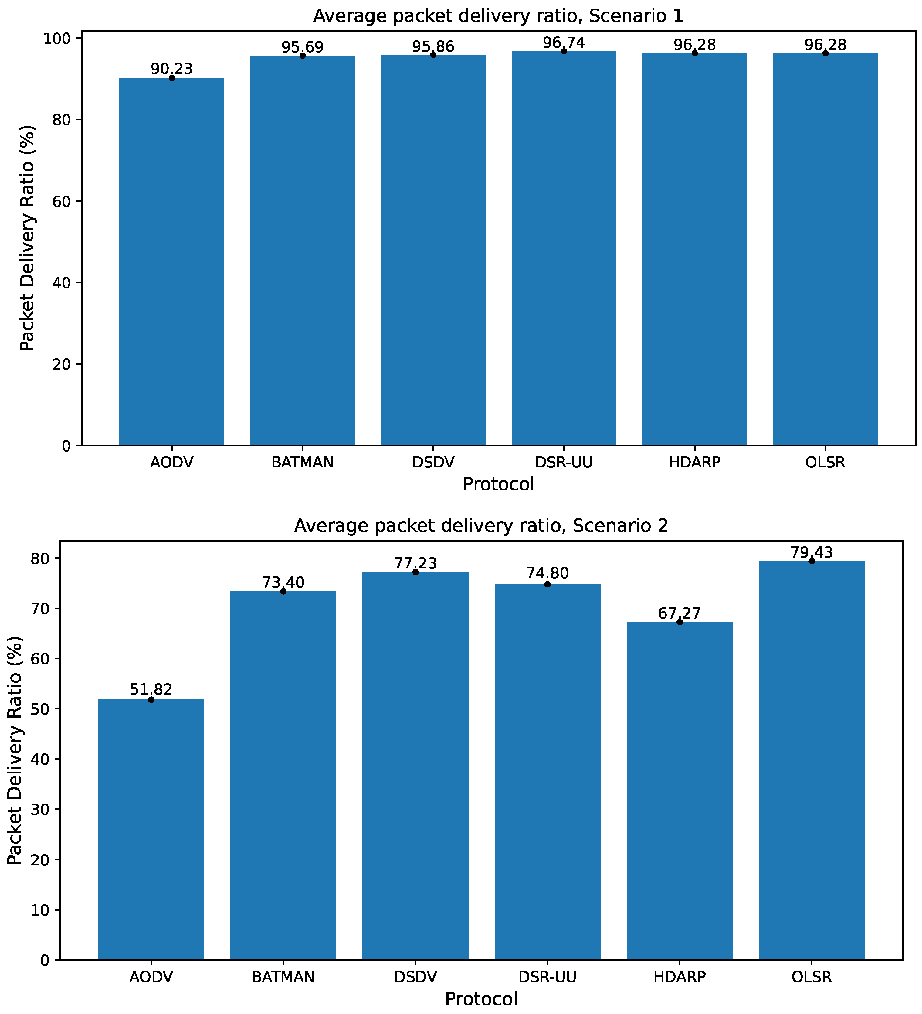
Figure 3 on the same frequency. Therefore, one could expect that the HDARP protocol could suffer from a low packet delivery ratio.
Figure 7 shows that the packet delivery ratio of the HDARP protocol is on a par with the best of the other protocols for Scenario 1 but a bit lower for Scenario 2. This means that the extra packet loss due to avoiding leakage seems limited. In some situations, HDARP will not be able to find a route that is free from leakage risks. However, in such cases, the packet will still be delivered (see how
weight is handled in Algorithm 4). This means that the lower packet delivery rate for Scenario 2 is not caused by HDARP not being able to find a route that is free from leakage risks. The very low number of leaked packets for HDARP (see
Figure 6) shows that HDARP was indeed able to find leakage-free routes in (virtually) all cases. The type of destructive interference mentioned here can be handled in the future by smart antenna arrays that multiplex multiple signals over time, frequency and angle of arrival.
In MANETs, there are two types of packets: packets containing user information (the payload provided through UdpBasicApp), e.g., voice communication between pilots and packets containing control information about the network and the network topology (i.e., routing messages). For each of our two scenarios, the number of packets containing user information is the same for all communication protocols. The number of packets containing control information, however, differs between different protocols.
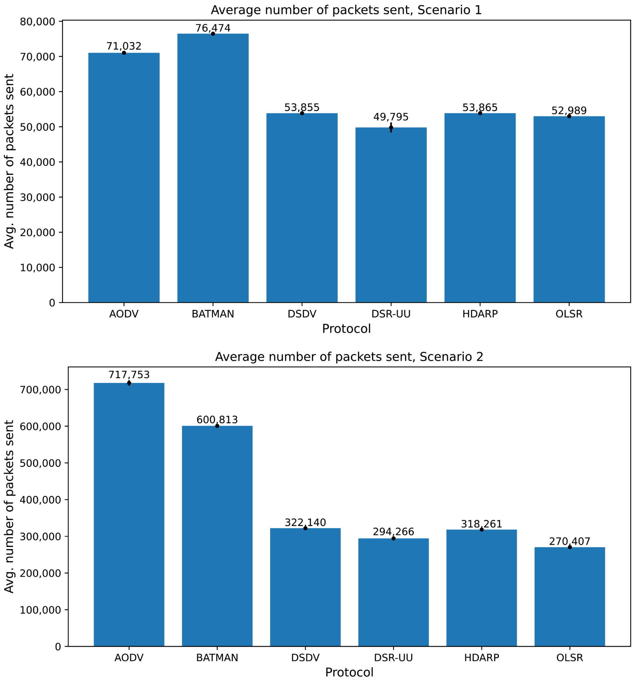
Figure 9 shows the total number of packets sent for the protocols considered here. The figure shows that DSR-UU and OLSR send a smaller number of packets than the HDARP protocol and that DSDV sends almost the same amount of packets for our two scenarios. This means that for HDARP, the number of packets containing control information is relatively small compared to most of the other protocols.
For HDARP, the control information consists of SA data, and SA data are something that the pilots need for tactical reasons regardless of which communication protocol is used. This means that the control information needed for the HDARP protocol needs to be distributed between the aircraft anyways. As a consequence,
Figure 9 does not give a completely fair picture of the number of packets sent, since the values for the other protocols do not include communication of SA data. In
Table 1, we see that the average time between UDP datagram transmissions is 150 milliseconds (uniform (0.1, 0.2)) and that the average time between SA update messages is 4 s (uniform (3, 5)). This means that during a 12 s interval, we receive 80 UDP datagram transmissions and 3 SA transmissions for each friendly node. Since 3/80 = 3.75%, one would think that we should multiply the number of sent packets with 1.0375 for all protocols except HDARP. However, SA data are only sent to nodes that are within a one-hop distance from the sender, and due to forbidden sectors, it may not be possible to reach all nodes in one hop. This means that the average number of SA packets sent from each friendly node is somewhat smaller than three during a 12 s interval. If we take this aspect into consideration, all values in
Figure 9 should be multiplied with a factor or 1.03 (and not 1.0375), except the values for the HDARP protocol. If we consider this multiplication, the HDARP protocol will have the second smallest number of packets sent for the R4B4 scenario (DSR-UU will still have the smallest number of sent packets) and the third smallest for the BVR scenario (DSR-UU and OLSR will still have a smaller number of sent packets). Since the SA data are the control information about the network topology for the HDARP protocol, it may seem surprising that some protocols have a lower number of sent packets. The reason for this that the forbidden sectors in HDARP cause more hops and each extra hop generates a sent packet.
6. Analysis and Discussion
Our experiments show that the HDARP protocol avoids adversary detection by minimizing the amount of leaked packets. The HDARP protocol uses situation awareness (SA) data when making routing decisions. The pilots of fighter jets need SA data for completing their missions. This means that SA data are used for two purposes: providing the pilots with mission critical information and for routing communication packets so that they cannot be detected by an adversary.
The HDARP protocol prevents leaking packets to an adversary by proactively trying to avoid transmitting in forbidden sectors. A consequence of this strategy is that a packet sometimes cannot be sent along a direct line between the sender and the destination. In such cases, the packet needs to be sent via an intermediate node (see
Figure 3). As a result of this, the number of hops will increase in some cases, and as a consequence, the average packet life time will also increase when we avoid leaking packets. Our experiments quantify this effect for the two scenarios considered. It turns out that compared to most protocols that do not avoid leaked packets, the average packet life time increased significantly for the more complex of the two scenarios (the BVR scenario). However, experts in the area of fighter jet design consider packet leakage to be a major tactical disadvantage from an operational perspective, and the cost in terms of longer average packet life time is therefore regarded as acceptable, depending on scenario at hand.
Our experiments show that using directional instead of omnidirectional antennas will reduce the number of leaked packets by several orders of magnitude. Similar reductions of the detection probability when using directional instead of omnidirectional antennas have been observed by other researchers [
45]. The HDARP protocol only works for directional antennas. However, when using directional antennas, simultaneous senders using the same frequency will not detect that the receiver suffers from destructive interference. As a consequence of this, some packets will be lost, resulting in a somewhat lower packet delivery rate for HDARP compared to the best of the omnidirectional protocols. Directional antennas can receive two packets on the same frequency simultaneously if the difference in angle of arrival (AOA) between the two senders is big enough. Our simulator does not consider the angle of arrival, which means that there will be destructive interference regardless of the AOA difference between the senders. This means that the packet delivery rates for HDARP shown in
Figure 7 are pessimistic and that the cost of using directional antennas and avoiding adversary detection in terms of a somewhat decreased packet delivery rate is acceptable.
The total number of sent packets is relatively small for the HDARP protocol. In fact, it is almost at the same level as the protocol with the smallest number of sent packets (DSR-UU). This means that SA data are a relatively efficient way of representing topology information about the mobile ad hoc network. As discussed previously, the pilots need SA data for completing their mission in any case. If we compensate for this, the difference between the number of packets sent by the HDARP protocol and the number of packets sent by DSR-UU becomes even more marginal. This means that the cost of avoiding adversary detection in terms of an increase in the number of sent packets is minimal and clearly acceptable.
In this paper, we base our evaluation on data from realistic flight scenarios used by the aerospace industry. Unfortunately, many studies of mobile ad hoc networks use very simplistic and unrealistic workload models, e.g., nodes with random movement patterns in a rectangular area [
46]. This project was conducted in close cooperation between researchers from academia and aerospace industry experts, which facilitates a high level of realism in the evaluation. In addition, the HDARP protocol is protected by a patent application, which demonstrates the expected importance and practical applicability of the HDARP protocol.
7. Conclusions
We have defined the Hostile-Direction Aware Routing Protocol (HDARP) that avoids detection by adversary aircraft in airborne tactical networks. HDARP uses directional antennas and avoids adversary detection by using so-called situation awareness (SA) data to determine a route such that the packets are not detected by hostile aircraft. SA data are needed in order for the pilots to perform their mission.
One of the advantages of HDARP, besides avoiding adversary detection, is that it uses already existing SA data for network topology control and routing decisions as well. Based on evaluations using realistic directional antenna models and flight scenarios from the defense industry, we have shown that the major tactical advantage of avoiding adversary detection comes at a relatively small, and clearly acceptable, cost in terms of somewhat longer packet lifetime and marginally lower packet delivery rate. Our evaluations also show that SA data provide a highly efficient way of representing network topology control, and the number of sent packets using HDARP is on a par with the best routing algorithms that do not avoid adversary detection. This means that the cost of avoiding adversary detection in terms of a slight increase of the number of sent packets is negligible.
In general, in this paper, we focus on the algorithmic properties of the protocol and not on the radio transmission protocol. In future work, we will consider looking at the effects of the radio protocol as well: examples include path loss, fading, and shadowing aspects. Further, we might also consider additional flight scenarios, different relations between flight speed and message propagation latencies. Finally, we have not tracked the beam width in our simulations. Theoretically, a narrow beam width decreases the probability of detection but potentially increases the average path length. Conversely, a wide beam width enables direct communication with more nodes, i.e., multicast, but potentially increases the probability of detection. We think that the trade-off between these two is a very interesting aspect that we consider for future work


 ,
, 


