

Beamforming Based on a SSS Angle Estimation Algorithm for 5G NR Networks


1
Instituto de Telecomunicações (IT) and Departamento de Eletrónica, Telecomunicações e Informática (DETI), University of Aveiro, 3810-193 Aveiro, Portugal
2
Allbesmart LDA, Avenida do Empresário, Centro de Empresas Inovadoras 1, 6000-767 Castelo Branco, Portugal
3
Instituto Politécnico de Castelo Branco (IPCB), Avenida Pedro Álvares Cabral 12, 6000-084 Castelo Branco, Portugal
*
Author to whom correspondence should be addressed.
Future Internet 2023, 15(3), 105; https://doi.org/10.3390/fi15030105
Submission received: 31 January 2023
/
Revised: 24 February 2023
/
Accepted: 6 March 2023
/
Published: 9 March 2023
(This article belongs to the Special Issue 5G Wireless Communication Networks)
Abstract
:The current 5G-NR standard includes the transmission of multiple synchronization signal blocks (SSBs) in different directions to be exploited in beamforming techniques. However, choosing a pair of these beams leads to performance degradation, mainly for the cases where the transmit and receive beams are not aligned, because it considers that only few fixed directions among wide beams are established. Therefore, in this article, we design a new 3GPP-standard- compliant beam pair selection algorithm based on secondary synchronization signal (SSS) angle estimation (BSAE) that makes use of multiple synchronization signal blocks (SSBs) to maximize the reference signal received power (RSRP) value at the receiver. This optimization is performed using the SSSs present in each SSB to perform channel estimation in the digital domain. Afterwards, the combination of those estimations is used to perform equivalent channel propagation matrix estimation without the analog processing effects. Finally, through the estimated channel propagation matrix, the angle that maximizes the RSRP is determined to compute the most suitable beam. The proposed algorithm was evaluated and compared with a conventional beam pair selection algorithm. Ours has better performance results. Furthermore, the proposed algorithm achieved performance close to the optimal performance, where all channel state information (CSI) is available, emphasizing the interest of the proposed approach for practical 5G mmWave mMIMO implementations.
Keywords:
5G; NR; 3GPP; massive MIMO; millimeter-wave communications; OFDM; PHY; RAN; beamforming; initial access; beam management1. Introduction
Due to the fast growing pace of high-speed mobile broadband demands triggered by the exponential increases in the numbers of users and distinct services [1,2], the third generation partnership project (3GPP) initiated the development and maintenance of the new radio (NR) access technology for the fifth generation (5G) mobile communications, according to a published set of recommendations that represent the basis for the implementation of 5G radio access networks all around the world [3,4]. Therefore, to fulfill the 5G performance requirements for the different use cases [5,6,7,8,9], the usage of the mmWave spectrum has been considered as a key technology to enable large radio bandwidths, overcoming the currently saturated frequency spectrum below 6 GHz used in LTE mobile systems. However, the use of higher frequencies for wireless communications is restricted by the harsher propagation characteristics of the mmWave systems that become even more hostile as the operation frequency increases [10].
To efficiently surpass these impairments, more sophisticated processing techniques are employed, such as beamforming (BF), which is capable of providing highly precise directional transmission links over multiple receive and transmit antenna elements [5,11], each one with detailed control of both phase adjustment and amplitude scaling to provide both high antenna-array and high spatial-multiplexing gains, overcoming the severe path losses of the mmWave systems [12] while being capable of achieving Gbps data rates in urban deployments [13,14,15]. Nonetheless, to achieve the most possible connectivity, there is a need to ensure that the established connection with each device occurs in the best possible set of beams.
This led to the creation of a distinct set of physical layer (PHY) L1/L2-interoperable procedures known as beam management (BM) procedures, consisting in a variety of control tasks, such as the determination of a suitable beamformed beam pair for idle users, establishing a connection between the device and the network, and retaining the best connectivity possible for already connected users through beam tracking processes, or even the beam recovery procedures needed to reestablish the connection with minimal delay after blockage events, gradual changes in the environment radio propagation conditions, or additional user movements and rotations [16,17].
The initial beam establishment (IBE) stage is the first of the three defined 3GPP BM procedures, which aims at establishing the best beam pair in the downlink (DL) and uplink (UL) directions. This is usually performed by measuring the different RSRP values for each of the transmit–receive candidate beam pairs in a dual-end beam-sweeping procedure, defined as procedure P-1 [18]. The corresponding beam pair link with the highest RSRP value is chosen, as it ideally experiences the best channel conditions available [19]. Therefore, relevant metrics to perform beam pair comparisons are fundamental in NR mobile systems for establishing the most suitable available connection.
The work proposed in this paper falls in this context. The main goal consisted of the design and subsequent performance evaluation of a new 3GPP-standard-compliant beam pair selection algorithm based on the SSSs angle estimation (BSAE). This BSAE algorithm was implemented in a NR system model that uses BM techniques at both transmitter (gNB) and receiver (UE) ends to establish the beamformed connection in the DL direction by choosing the best beam pair available for further synchronization, demodulation, and decoding a real-time gNB signal.
1.1. Previous Works on Beam-Pair Selection Enhancement
Although a set of 3GPP specifications have been already defined for the suitable beam pair selection of the highly directional transmissions required to enable the communication in the mmWave frequency bands, there is a lot of flexibility in how the required procedures are implemented.
The authors of [20] proposed a directional cell discovery procedure, where BSs periodically transmit synchronization signals (SSs) in both time-varying random and omnidirectional directions to scan the angular space. The results, derived from actual field measurements for both single and multipath channels, showed that omnidirectional transmissions of SSs have much better performances than random angular search, in both digital and analog cases. Additionally, it was suggested that a low-rate-per-antenna digital BF design with an appropriate search algorithm may be a better choice for the initial cell search, and hybrid or analog BF should be used for the remaining communications once the connection has finally been established in both directions. An extension to the previous work was presented in [21], where the authors proposed several different standalone mmWave design options for the directional search in the initial access (IA) procedure, comprising both the synchronization phase, where the UE discovers the BS, and the random access phase, where the BS detects the random access request from the UE.
The work in [22] focused on the mitigation of the total duration of IA-directional searching. They revisited various techniques for exhaustive and iterative beam searching to propose a novel hybrid training method, where the BS performs wide beam searching in the first stage, and the UE performs reverse training according to the best wide beam decided in the first stage. This more complex implementation is based on the initial transmission of SSs in a few directions over wide beams, which are subsequently refined until the communication is satisfactorily directional. Further work motivated by the reduction in the unacceptable overhead of traditional exhaustive searching schemes that lead to substantial delays on real-time communications was presented in [23]. The proposed data-driven multi-armed beam tracking scheme speeds up the beam tracking process by selecting the beamforming/combining vectors that achieve the target quality of service (QoS) based on real-time measurements, rather than the prior knowledge, such as channel and user mobility information in beamforming design. To address the trade-off between maximizing the QoS and minimizing the training latency, the authors of [24] designed an adaptive data-driven beam tracking scheme for multi-user mmWave communication systems. They used real-time measurement data based on a dynamic linearization representation of a time-varying pseudo-gradient parameter estimation procedure. To guarantee the reliability of communication, adaptive data-driven beam tracking was proposed to find a suitable beamformer/combiner pair and meet the given SINR constraint.
There is also some additional work based on several sources of side information that successfully help the establishment of the mmWave links with substantially reduced training overheads for the beam-selection stage. Such work included the use of spatial information retrieved from sub-6 GHz frequency bands in an analog mmWave system, proposed in [25]; the leveraging of vehicle’s position information and past beam measurements to rank desirable pointing directions that can reduce the required beam training to a small set of pointing directions, discussed in [26]; and also a novel framework of 3D-scene-based beam selection information for mmWave communications, proposed by the authors of [27]. This last work relied only on the environmental data and deep learning techniques of neural networks, used alongside image processing techniques, to improve the suitable beam selection. The proposed approach can predict the optimal beam pair for any point in the current cell and can further work for a new environment with the same type of building distribution.
Moreover, a BM strategy based on a conjunction of beam-orientation information retrieved from on-board sensors at the UE with RSRP measurements, was proposed in [28] to improve beam determination accuracy and achieve reduced power transmission values, allowing a considerable higher UE battery life. In this algorithm, the source of side-information is at the UE, and thus, it requires no additional signaling overhead to be used for the optimal transmit and receive beam pair predictions.
In [29], a beam pair selection algorithm was presented that deploys BM procedures at both next-generation node B (gNB) and UE ends of a NR system to acquire a set of beam pair links using SSBs transmitted as a burst in the downlink (DL) direction. In this algorithm, a set of beamformed SSBs is swept over both azimuth and elevation directions to be further transmitted over a spatial-scattering channel and consequently processed over multiple receive-end beams. Afterwards, the RSRP values for each correspondent transmit–receive beam pair combination are measured, and the beam pair link with the maximum RSRP value is chosen as the most suitable one for establishing the connection.
Most of the approaches referred to above consider that only few directions over wide beams are established, and then the beams are refined until we get the best beam pair. This can result in a delay in achieving good communication, or even losing communication before it is properly established. Other approaches are too complex, which can be a strong limitation for real-time systems. Therefore, to avoid both high computational complexity and taking a very long time to find the best pair of beams, we exploit the information obtained from all received SSBs, instead of selecting the beam corresponding to the best RSRP followed by the refinement process. In this way, it is possible to optimize the receiver-side beam by aligning it with the already gNB selected beam, leading to better performance results for the IBE stage.
1.2. Contributions
In this paper, we propose a new algorithm for 5G NR beam pair selection at the IBE stage, referred as BSAE. The main contributions of this work include:
- The design of a new 3GPP-standard-compliant algorithm that aims to improve the beam pair selection stage by using multiple synchronization signal blocks (SSBs) to maximize the RSRP value at the receiver, considering the equivalent channel propagation matrix estimation based on SSSs to subsequently enhance the overall performance of the system.
- The optimization is performed using the SSSs present in each SSB to perform channel estimation in the digital domain, which contains the analog processing effects. Subsequently, the set of those estimations are used to estimate the channel without the analog equalizer effect, providing information about the spatial correlation of the channel. Finally, through the estimated channel propagation matrix, the angle that maximizes the RSRP is determined to compute the most suitable beam.
- Simulation and performance analysis comparison of different beam pair selection algorithms employed in an NR system that makes use of BM procedures at both gNB and UE ends for the IBE process.
The simulation results show that the proposed BSAE algorithm achieves better performance than a conventional beam pair selection algorithm based on RSRP maximization in terms of the physical broadcast channel (PBCH), physical downlink control channel (PDCCH), and physical downlink shared channel (PDSCH) throughput.
1.3. Notation
A matrix A is denoted by boldface capital letters, and the column vector a is denoted by boldface lowercase letters. The operations trace, the conjugate, the transpose and the Hermitian of a matrix, are denoted by , , , and , respectively. Finally, the index represents the subcarrier, and s represents the analog beam at the UE.
2. System Model
In this section, a detailed description of the gNB, channel, and UE model considered for the application of BM procedures in both gNB and UE-side directions during IA is presented, where the simulated system uses both the 5G toolbox and the Phased Array System Toolbox. The first one provides 3GPP-standard-compliant functions and reference examples useful for modelling and simulation of a 5G NR end-to-end communication system, given the DL’s physical channel and signal creation for transmission and reception of downlink control information (DCI) messages to the DL synchronization, demodulation, and further decoding of a live gNB signal at the UE. On the other hand, the Phased Array System Toolbox provides the necessary algorithms for enabling BF techniques with electronically steerable antennas, allowing the simulation of multipath fading environments to evaluate the performance of the employed BF antenna arrays.
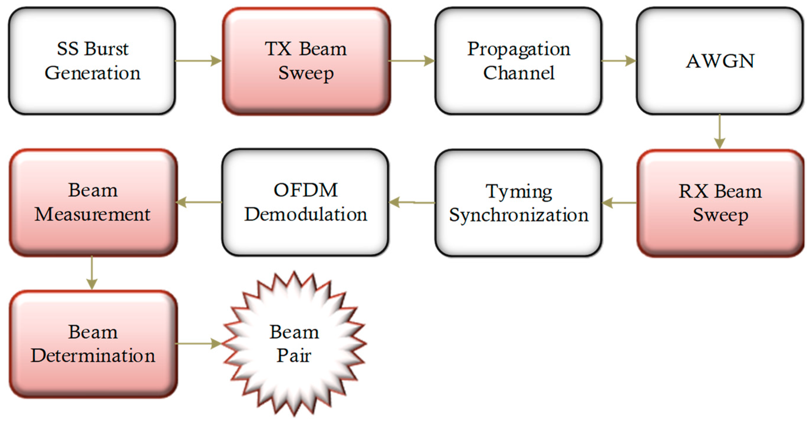
An overview of the main processing stages required for the dual-end beam-sweeping procedure at both the gNB and the UE ends, along with the main BM steps for effective beam pair establishment and maintenance, are highlighted in red in Figure 1.
2.1. Transmitter Model Description
The transmitter, gNB, equipped with antennas, is responsible for the generation and transmission of a DL waveform, which is subject to some BM techniques used in the IA procedure for establishment of an effective connection between the gNB and the UE. After that, an SS burst is generated and configured carrying the master information block (MIB) and the demodulation reference signals (DMRS) for the PBCH demodulation. Then each SSB is beamformed within the burst and swept over both azimuth and elevation specified directions within the SS burst’s periodicity. This beamformed signal is then transmitted over a spatial-scattering channel, which is presented in the following section, and then processed over each one of the multiple receive-end beams in a dual-end beam-sweeping process [16,18].
2.2. Channel Model Description
A spatial scattering MIMO channel is used, modeling a LoS multipath propagation channel where the transmitted signals are reflected from multiple scatterers to the receiver [10]. This channel model applies free-space path loss and specifies the locations for both the BS and UE as coordinates in a Cartesian system, consisting of both a uniform rectangular array (URA) and a uniform linear array (ULA) with isotropic antenna elements at the gNB and UE, respectively. Moreover, to simulate the noise in the actual propagation medium, distributed and uncorrelated additive white Gaussian noise (AWGN) is added to the transmitted signal.
The spatial scene illustrating a combined view of the channel scatterers along with the gNB and UE determined beams is presented in Figure 2:
2.3. Receiver Model Description
The UE is responsible for several synchronization and demodulation processes of the received waveform to determine the physical cell identity (PCI), and decodes the MIB and then the DCI in the PDCCH. Furthermore, the UE uses the DCI to decode the downlink shared channel (DL-SCH) and finally recover the transport block (TB) information.
Following the signal transmission by the gNB, the UE performs the first step to acquire DL synchronization, corresponding to a cell-search procedure firstly detecting the PSS, which is allocated to 127 subcarriers of the first symbol within each SSB [30], performing time-offset compensation. Once both the reference PSS sequence and the received waveform are aligned, the UE also obtains one of the 336 possible SSS sequences () for an effective PCI computation [30,31]. After having computed the PCI, the UE determines the frequency-domain position of the DM-RS candidates in the PBCH and performs both channel and additive-noise estimations [30]. This previously described procedure is repeated for every SSBs, and these channel estimations are used to compute the most suitable beam pair, based on the proposed BSAE algorithm. Then, the UE proceeds with the demodulation and decoding of the PBCH [30,32] to successfully acquire the MIB message [33], where a combination of system frame number (SFN), half radio frame bit, and the frequency domain offset between SSB and the overall RB grid in number of subcarriers parameters allow the acquisition of radio-frame synchronization and slot timing, completing the cell-search procedure. Subsequently, the UE proceeds by trying to demodulate the PDCCH and blindly search for DCI-format messages to get both the frequency and time resources of the PDSCH [33]. Finally, the UE performs the PDSCH decoding.
3. Proposed Beamforming Based on SSS Angle Estimation Algorithm
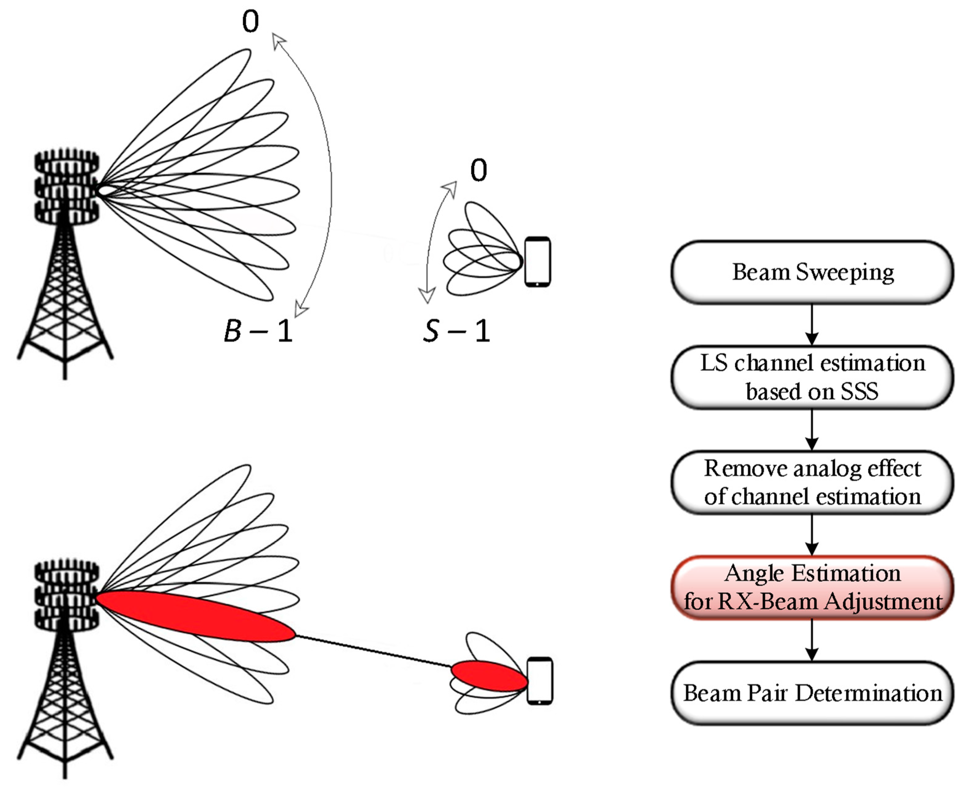
An illustration of the proposed BSAE algorithm’s concept is presented in Figure 3.
To achieve better system performance levels in the effective decoding of the transmitted information, the UE can additionally use the SSS in combination with DMRSs to determine the impact of the propagation channel and then apply the inverse to the PBCH payload before the decoding attempt, since these two signals experience similar propagation-channel effects. However, the UE processing is carried out after analog-to-digital (ADC) conversion, and thus, to efficiently perform better UE beam angle adjustments, equivalent channel estimation of the analog part is required. When considering a DL system with a BS equipped with transmit antennas transmitting SSBs over beams, and a single user equipped with a single radio frequency (RF) chain, receive antennas, and possible beams at the IBE stage, the received SSS signal at the kth subcarrier for the sth analog beam, at the UE, is given by
where the is the transmitted SSS at the subcarrier k, and the vectors and model the analog beam at the BS and the UE, respectively. Additionally, is the frequency-domain channel at subcarrier k, and the parameter denotes the zero-mean Gaussian noise, with variance
Having the transmitted and received SSSs, the equivalent channel is estimated by
At this point, the equivalent channel estimated in Equation (2) contains the needed analog counterpart estimation. Considering where S is the number of beams in the beam-sweeping procedure, and Then, from Equation (2), we have,
Therefore, by applying the pseudo-inverse of the to Equation (3), we can estimate the channel in the analog part, , by
Hence, the receive beamformer, , can be found by solving the following optimization problem, through the interactive greedy method:
where is the set of feasible vectors and is the array response vector for angle such that is the dictionary size
where is the wavelength and is the inter-element spacing.
The proposed BSAE algorithm is summarized in the following algorithm (Algorithm 1). First, in line 2, we start by generating the weights for every transmitted beam directions, with angles , where and are the minimum and maximum azimuth angles, respectively; and , where and are the minimum and maximum elevation angles, respectively, with The indexes and are the antenna indexes such that . Then, in line 5, we generate the weights for every received steered beam direction, with angle , where and are the minimum and maximum azimuth angles, respectively. Next, in line 6, we extract the received SSS and, in line 7, we obtain the SSSs symbols for the computed PCI. Afterwards, in line 8, we perform the channel propagation matrix estimation in the digital part based on SSS, which comprises the effects of the analog processing. In line 10, we perform the channel propagation matrix estimation in the analog part to remove the analog equalizer processing effects. Finally, this matrix is then used for metric evaluation of the different steering angles to determine the one that maximizes the RSRP and compute a best suitable adjusted beam at the UE end.
| Algorithm 1: Proposed BSAE algorithm | ||
| 1 | for do | |
| 2 | ||
| 3 | end | |
| 4 | for do | |
| 5 | ||
| 6 | ||
| 7 | Get for computed PCI | |
| 8 | ||
| 9 | end | |
| 10 | ||
| 11 | ||
Real-Time Complexity Analysis
In this section, we evaluate the complexity of the proposed BSAE algorithm, which may be divided into two parts: (1) pre-allocated matrices and (2) real-time processing.
The generated weights in the steps performed between lines 1 and 5 are pre-allocated, and thus they do not impact the real-time performance. Additionally, the channel estimation is performed in lines 6–8, where the first two steps present a negligible impact when compared to the operation performed in line 8. For the computation of line 8, we perform divisions, where is the number of SSSs symbols. This step corresponds to a complexity of , where n is the number of digits of the SSS symbols. We repeat this computation times, and thus, the complexity at this point is .
In line 10, we compute Equation (4), which requires the inversion of a matrix, whose complexity is , and then we multiply the result by a matrix with the complexity of . Therefore, the complexity of computing the Equation (4) is .
Finally, the metric of optimization problem (5) in line 11 has a complexity level of , which is evaluated times, so the complexity of the optimization problem (5) is . Therefore, the total complexity computation of the proposed BSAE algorithm is .
In [29], the algorithm can also be divided into two parts: (1) pre-allocated matrices and (2) real-time processing. The first steps also correspond to pre-allocated operations, where the weights for the steered beam directions are generated, and thus, similarly to the proposed BSAE algorithm, they do not impact the real-time performance. For the computation of the RSRP, multiplications are performed, followed by the addition operation of these values and a final division operation, which leads to a complexity at this point of . This step is repeated times, and then the best beam pair link is selected. Thus, the total complexity computation of the algorithm presented in [29] is .
When comparing the complexity computation between the two algorithms, the one that presents more complexity is dependent on the scenario. The algorithm present in [29] has a dominant term of , and in some cases—for example, when , i.e., , , and have small values relative to and —the proposed BSAE algorithm has less computational complexity because . Otherwise, the terms or could overcome the term .
4. Numerical Results
In this section, the simulated performance results of the proposed beam pair selection algorithm is presented in terms of correct MIB, DCI and DL-SCH decoding percentages alongside with the bit error rate (BER) metric, shown as a function of , where is the average bit energy and is the one-sided noise power spectral density. The Quadrature phase-shift keying (QPSK) is the modulation scheme adopted in this section and the transport block size (TBS) is 176.
The simulation was performed for three different algorithms, whose vectors specifying the antenna element array sizes comprised a two-element row vector specifying the number of antenna elements in the rows and columns. A URA vector specifying the antenna element array sizes is used when both values are greater than one, and a ULA is assumed if any of the values is one. The three different simulated algorithms were:
- Beam pair selection based on the RSRP maximization algorithm proposed in [29];
- Optimum beam pair angle selection algorithm, for comparison purposes;
- Proposed BSAE algorithm.
The considered optimum beam pair selection algorithm corresponds to the case where the real channel matrix is used to compute the optimal UE angle; however, since this matrix is not known in practical implementations, this algorithm is not feasible in real-time scenarios.
In each simulation, for the sake of simplicity, a single cell scenario with only one BS and one UE was considered for both FR1- and FR2-mode operation (normal CP values). The considered transmit array was an URA with 64, whereas the receive array employed an ULA type configuration with 16. Additionally, there were eight SSBs per SS burst for the frequency-mode operation.
A more complete list of system parameters used for the three algorithms mentioned above is presented in Table 1:
4.1. FR1 Operation Mode
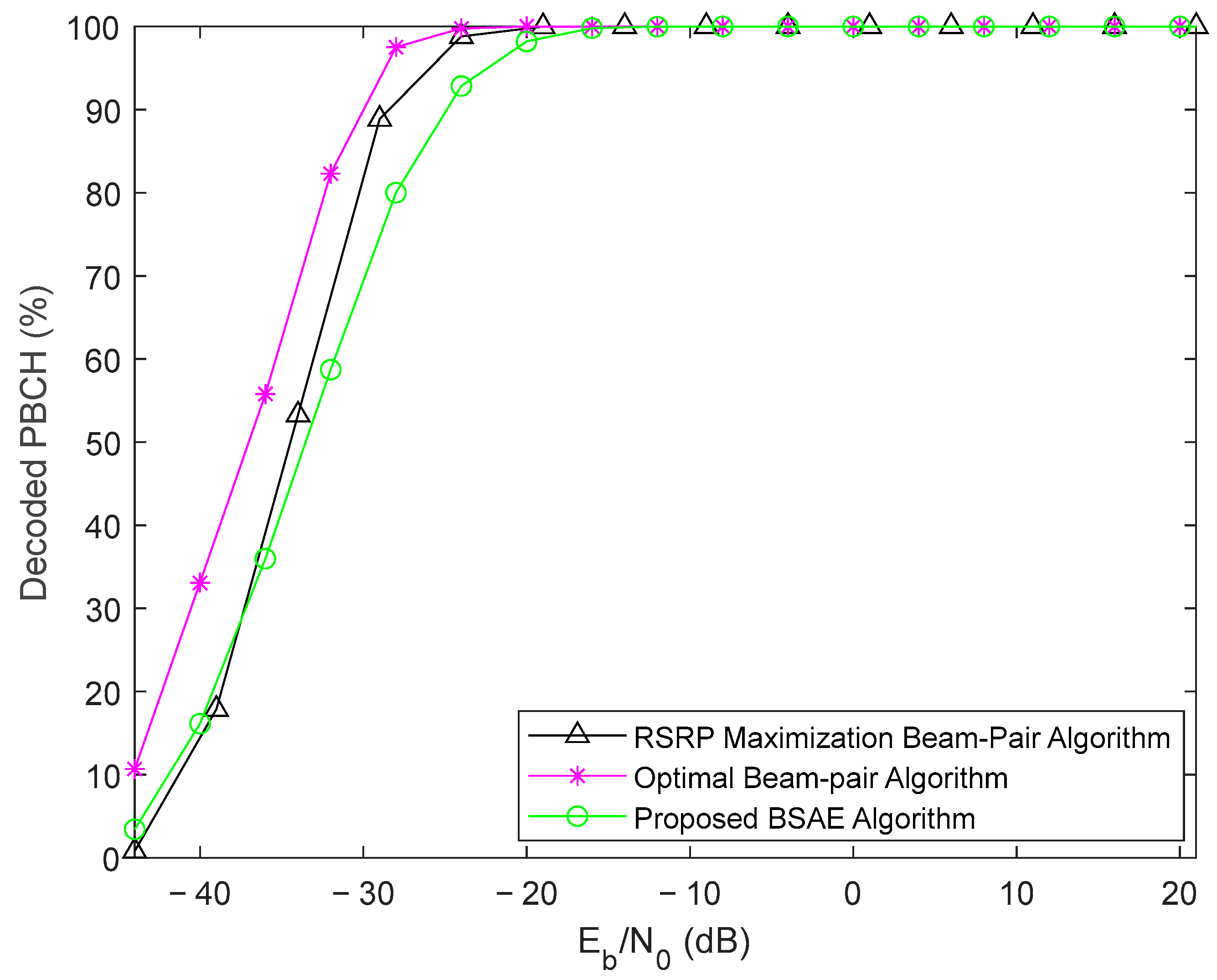
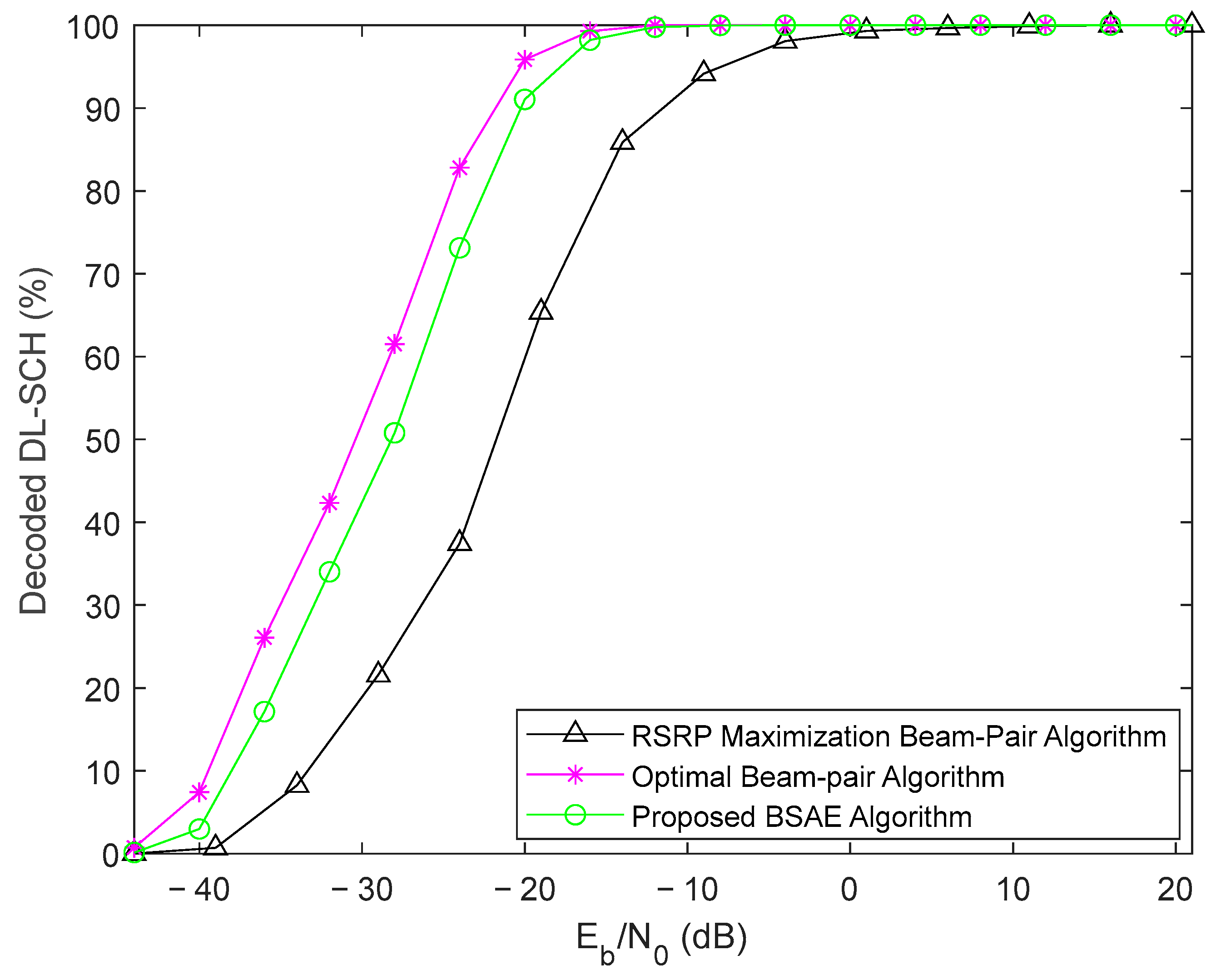
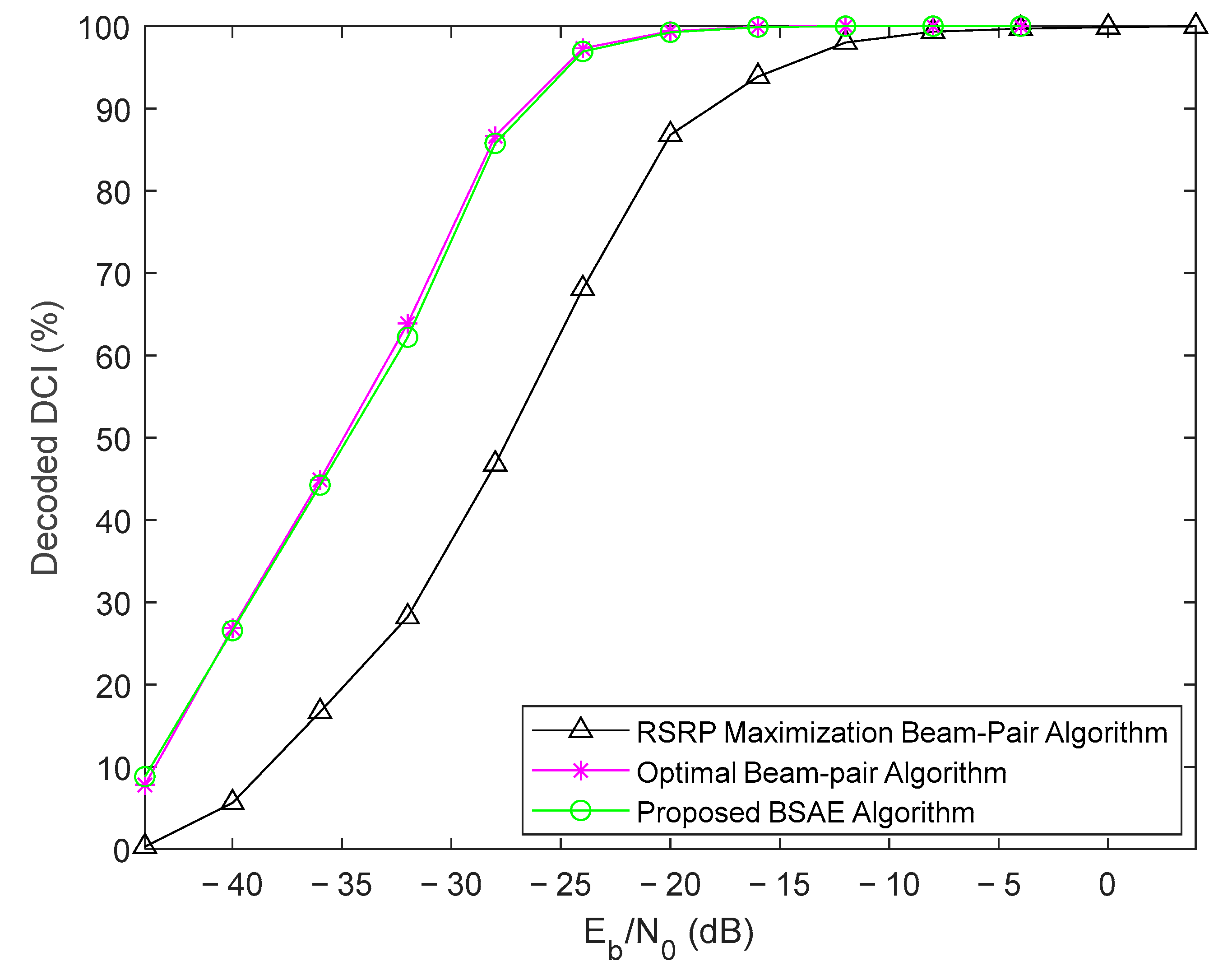
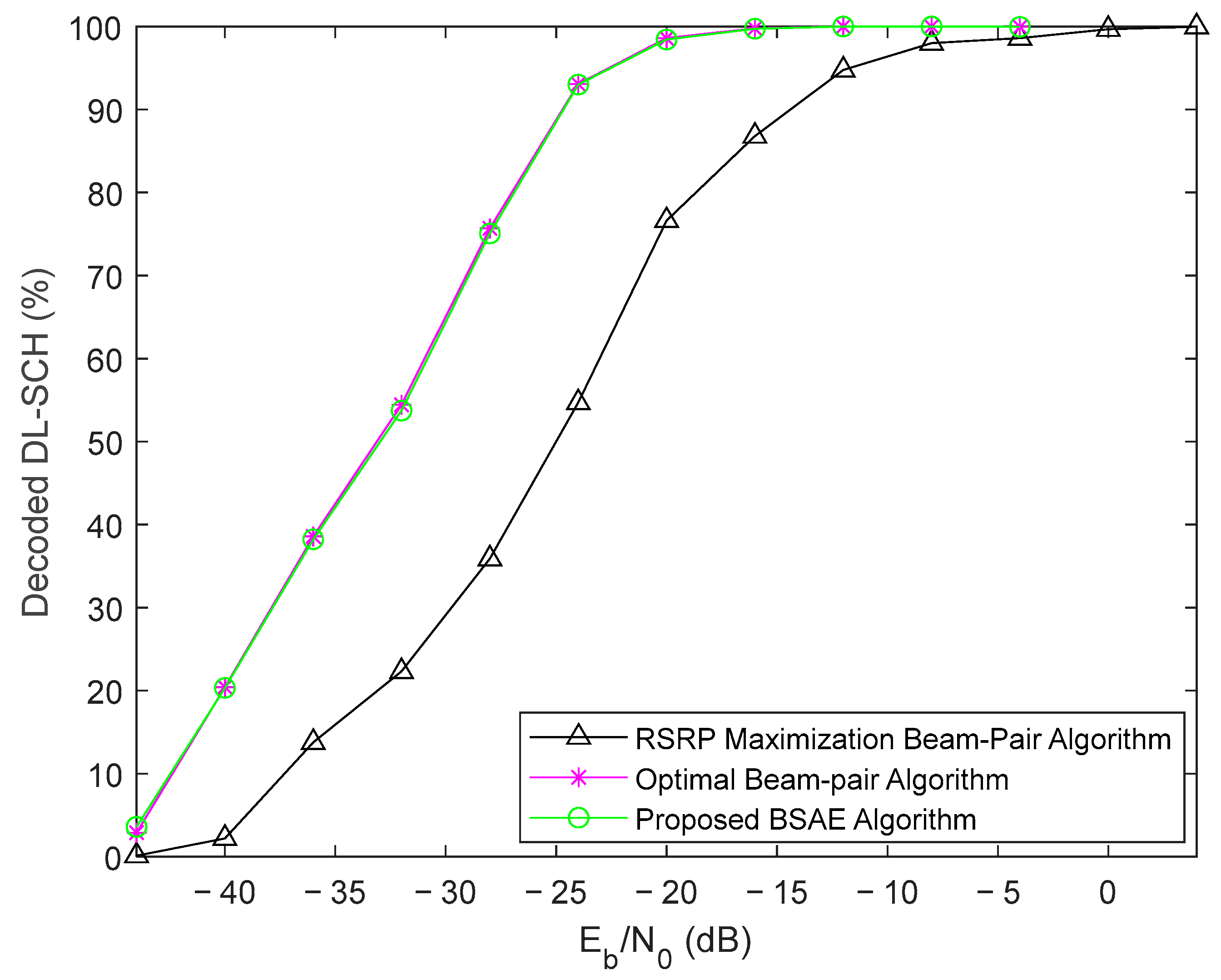
Figure 4, Figure 5 and Figure 6 illustrate the comparison of the different decoding percentages of the DL PHY channels of the three algorithms referred to above for the FR1 operation mode. Despite the lower effective PBCH decoding throughput of the designed BSAE algorithm, we can verify an enhancement in the DL-SCH decoding percentages. This exists because the algorithm presented in [29] only uses a few possible beams, since it is limited to the tested beams, whereas in the proposed BSAE algorithm, we do not have this limitation because we use the estimated spatial correlation matrix, which allows us to use any angle that maximizes the RSRP.
The worst performance of this mentioned beam pair selection algorithm based on RSRP maximization is noticeable. Almost all TBs were only successfully decoded above = 0 dB. Moreover, the BSAE algorithm achieved 100% throughput for values higher than = −12 dB, which corresponds to a 12 dB performance gain. By comparing the DL-SCH decoding throughput between the proposed and an optimal beam pair determination algorithm, it is still possible to observe similar performances.
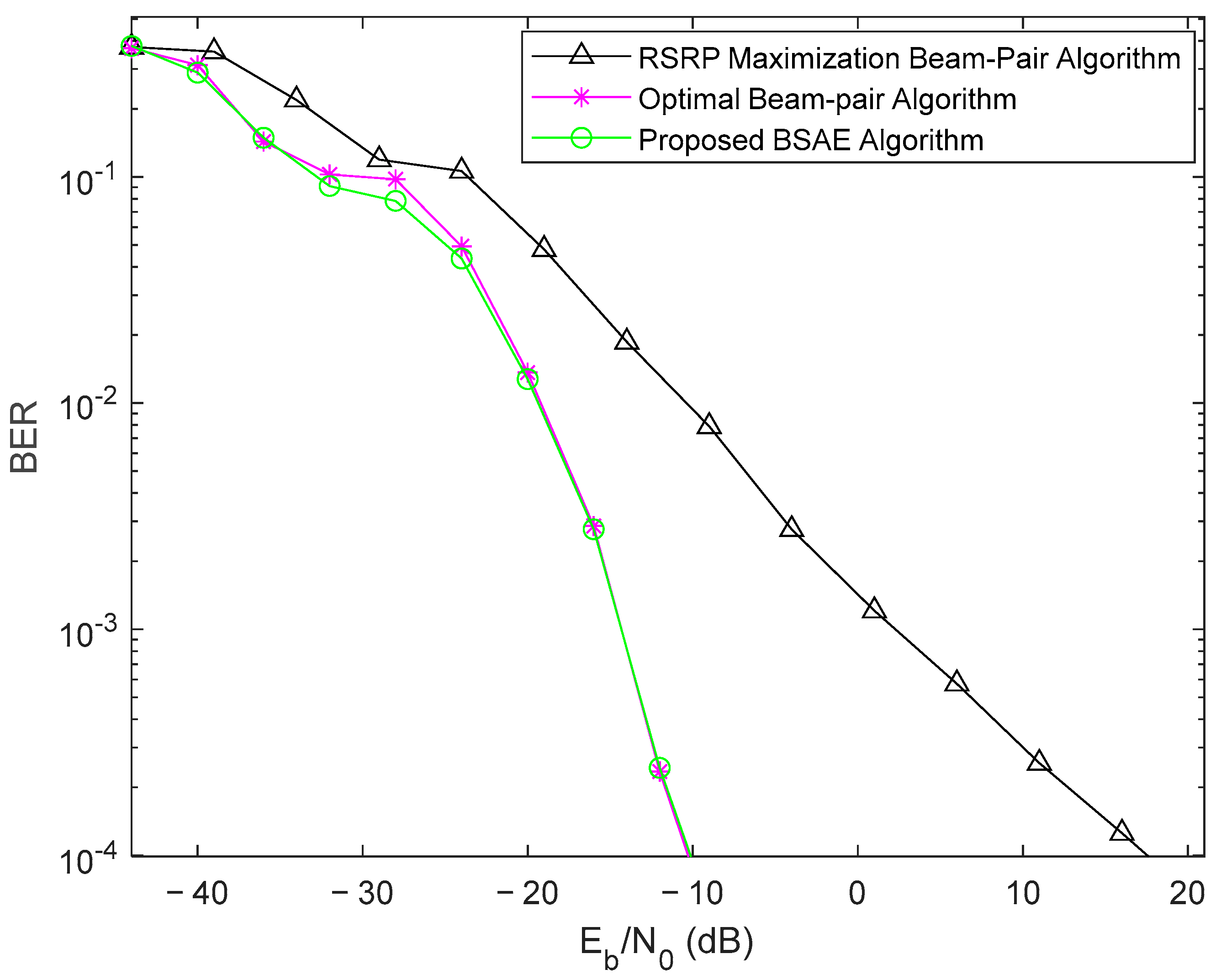
The respective performance results in terms of BER for the three algorithms mentioned above are presented in Figure 7, where the proposed BSAE algorithm presents a clear improvement over the beam pair selection based on the RSRP maximization algorithm. The performance gain was around 17.5 dB at the BER target of .
4.2. FR2 Operation Mode
In a similar way to the previous results, Figure 8, Figure 9 and Figure 10 illustrate the comparison of the different decoding percentages of the DL PHY channels of the three considered algorithms for the FR2 operation mode. We can verify that the designed BSAE algorithm resulted in higher channel-decoding percentages compared to the beam pair selection algorithm based on RSRP maximization. Additionally, the BSAE algorithm achieved 100% throughput for values higher than = −24 dB, which corresponds to a 4 dB performance gain. When comparing the decoding throughputs of the proposed and an optimal beam pair determination algorithm, it is still possible to observe similar performances.
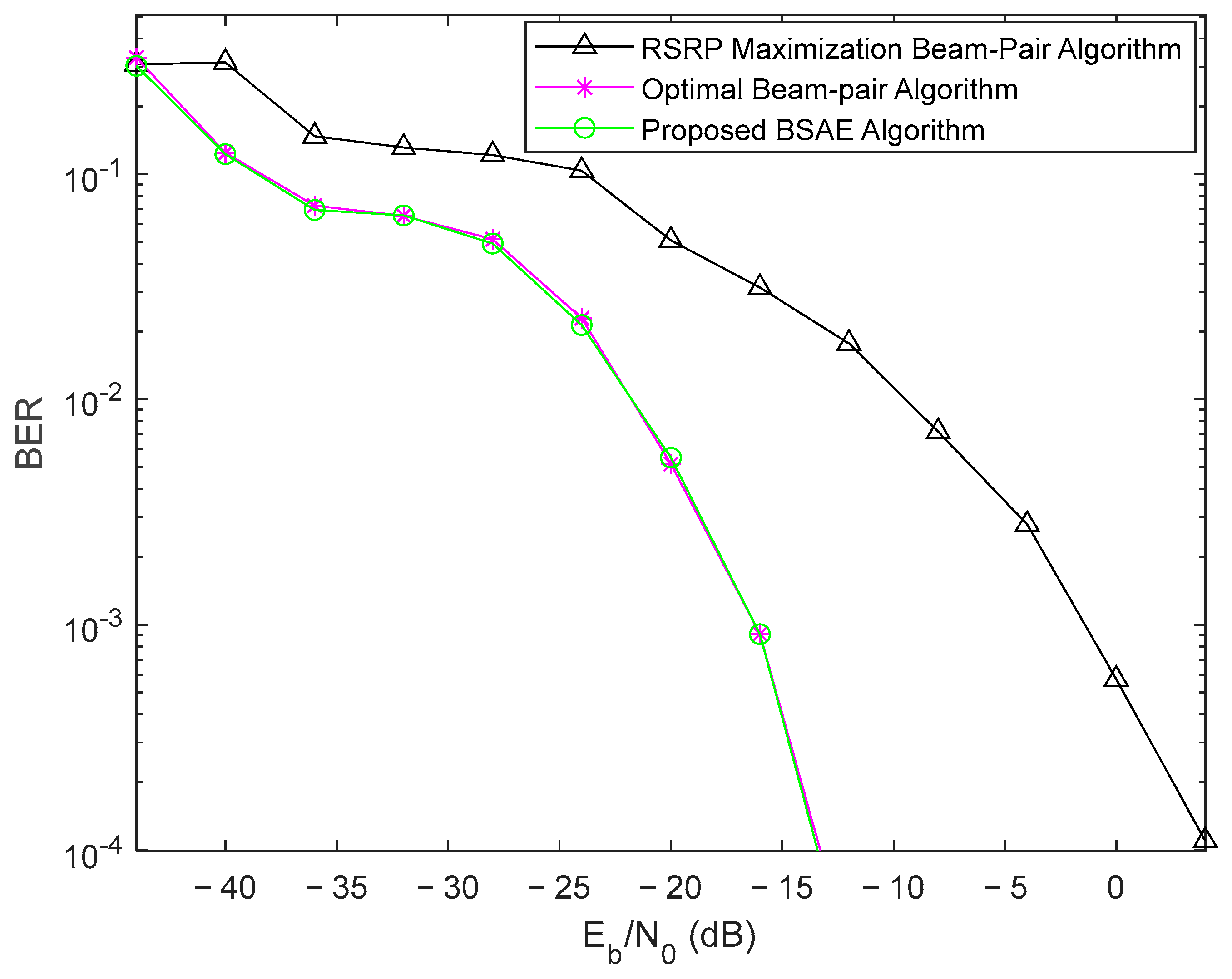
The respective performance results in terms of BER are presented in Figure 11, where the proposed BSAE algorithm presents a clear improvement over beam pair selection based on the RSRP maximization algorithm. The performance gain is around 15 dB at the BER target of .
5. Conclusions
In this paper, a new 3GPP-standard-compliant BSAE algorithm was designed, and a testing environment was created for different scenarios and configurations, focusing on BM procedures for idle users during IA. The system employs beam-sweeping techniques at both the gNB and UE ends to beamform each SSB within the burst through a spatial-scattering channel for subsequent UE signal processing over the multiple receive-end beams. Then, after we perform RSRP measurements for each of the transmit–receive beam pairs, the pair with the maximum RSRP value was chosen as the most suitable beam pair. At this stage, the UE performs cell -election procedures for the blind decoding of the DCI in the PDCCH. Finally, the UE decodes the PDSCH to successfully recover the transmitted information.
From the results, it can be concluded that the design and employment of efficient algorithms that explore BM procedures for beam pair selection are of extreme importance and have significant impacts on the overall performance of the system. The results obtained for the designed BSAE algorithm showed a considerable performance improvement over the beam pair determination algorithm based on the RSRP maximization without the addition of much complexity. This emphasizes the benefits of designing algorithms that consider information about all the candidate beam pairs for effective, enhanced beam pair selection between the gNB and the UE. Additionally, when comparing the results between the proposed BSAE algorithm and the optimal case, similar performances were also noticeable, highlighting its potential for practical 5G mmWave mMIMO implementations following 3GPP-compliant standards.
Author Contributions
Investigation, D.A. and R.M.; supervision, A.S., P.M. and R.M.; validation, A.S., P.M. and R.M.; writing—original draft, D.A.; writing—review and editing, A.S. and P.M. All authors have read and agreed to the published version of the manuscript.
Funding
This work is funded in part by FCT/MCTES through national funds and when applicable co-funded by EU funds under the project UIDB/50008/2020-UIDP/50008/2020 and by Fundo Europeu de Desenvolvimento Regional (FEDER) through POCI-01-0247-FEDER-072224.
Institutional Review Board Statement
Not applicable.
Informed Consent Statement
Not applicable.
Data Availability Statement
Not applicable.
Conflicts of Interest
The authors declare no conflict of interest.
References
- 3GPP. TR 22.861: Massive Internet of Things; v14.1.0. Tech. Spec. 2016. Available online: https://portal.3gpp.org/desktopmodules/Specifications/SpecificationDetails.aspx?specificationId=3013 (accessed on 8 December 2022).
- Chettri, L.; Bera, R. A Comprehensive Survey on Interneet of Things (IoT) Toward 5G Wireless Systems. IEEE Internet Things J. 2020, 7, 16–32. [Google Scholar] [CrossRef]
- Rost, P.; Banchs, A.; Berberana, I.; Breitbach, M.; Doll, M.; Droste, H.; Mannweiler, C.; Puente, M.A.; Samdanis, K.; Sayadi, B. Mobile network architecture evolution toward 5G. IEEE Commun. Mag. 2016, 54, 84–91. [Google Scholar] [CrossRef] [Green Version]
- ITU-R. Detailed specifications of the terrestrial radio interfaces of International Mobile Tellecomunications-2020 (IMT-2020). Recommendation ITU-R M.2150-1, February 2022. Available online: https://www.itu.int/dms_pubrec/itu-r/rec/m/R-REC-M.2150-1-202202-I!!PDF-E.pdf (accessed on 8 December 2022).
- ITU-R. IMT Vision- Framework and overall objectives of the future development of IMT for 2020 and beyond. M Series 2083-0, September 2015. Available online: https://www.itu.int/dms_pubrec/itu-r/rec/m/R-REC-M.2083-0-201509-I!!PDF-E.pdf (accessed on 8 December 2022).
- Dahlman, E.; Mildh, G.; Parkvall, S.; Peisa, J.; Sachs, J.; Selén, Y.; Sköld, J. 5G wireless access: Requirements and realization. IEEE Commun. Mag. 2014, 52, 42–47. [Google Scholar] [CrossRef]
- 3GPP. TR 22.863: Feasibility Study on New Services and Markets Technology Enablers for Enhanced Mobile Broadband; v14.1.0. Tech. Rep. 2016. Available online: https://portal.3gpp.org/desktopmodules/Specifications/SpecificationDetails.aspx?specificationId=3015 (accessed on 8 December 2022).
- 3GPP. TS.22.368: Service requirements for Machine-Type Communications (MTC); v17.0.0. Tech. Spec. 2022. Available online: https://portal.3gpp.org/desktopmodules/Specifications/SpecificationDetails.aspx?specificationId=645 (accessed on 8 December 2022).
- 3GPP. TR 22.862: Feasibility Study on New Services and Markets Technology Enablers for Critical Communications; v14.1.0. Tech. Spec. 2016. Available online: https://portal.3gpp.org/desktopmodules/Specifications/SpecificationDetails.aspx?specificationId=3014 (accessed on 8 December 2022).
- Hemadeh, I.; El-Hajjar, M.; Katla, S.; Hanzo, L. Millimeter-Wave Communications: Physical Channel Models, Design Considerations, Antenna Constructions and Link-Budget. IEEE Commun. Surv. Tutor. 2017, 20, 870–913. [Google Scholar] [CrossRef] [Green Version]
- Baldemair, R.; Dahlman, E.; Fodor, G.; Mildh, G.; Parkvall, S.; Selen, Y.; Tullberg, H.; Balachandran, K. Evolving Wireless Communications: Addressing the Challenges and Expectations of the Future. IEEE Veh. Technol. Mag. 2013, 8, 24–30. [Google Scholar] [CrossRef]
- Larsson, E.G.; Edfors, O.; Tufvesson, F.; Marzetta, T.L. Massive MIMO for next generation wireless systems. IEEE Commun. Mag. 2014, 52, 186–195. [Google Scholar] [CrossRef] [Green Version]
- Pi, Z.; Khan, F. An introduction to millimeter-wave mobile broadband systems. IEEE Commun. Mag. 2011, 49, 101–107. [Google Scholar] [CrossRef]
- Roh, W.; Seol, J.-Y.; Park, J.; Lee, B.; Lee, J.; Kim, Y.; Cho, J.; Cheun, K.; Aryanfar, F. Millimeter-Wave Beamforming as an enabling Technology for 5G Cellular Communications: Theoretical Feseability and Prototype Results. IEEE Commun. Mag. 2014, 52, 106–113. [Google Scholar] [CrossRef]
- Yong, S.K.; Chong, C.-C. An overview of multigigabit wireless through millimeter wave technology: Potentials and technical challenges. EURASIP J. Wirel. Commun. Netw. 2007, 2007, 078907. [Google Scholar] [CrossRef] [Green Version]
- 3GPP. TR 38.802: Study on New Radio Access Technology Physical Layer Aspects; v14.2.0. Tech. Rep. 2017. Available online: https://portal.3gpp.org/desktopmodules/Specifications/SpecificationDetails.aspx?specificationId=3066 (accessed on 8 December 2022).
- Giordani, M.; Mezzavilla, M.; Barati, C.N.; Rangan, S.; Zorzi, M. Comparative analisys of initial access techniques in 5G mmWave cellular networks. In Proceedings of the 2016 Annual Conference on Information Science and Systems (CISS), Princeton, NJ, USA, 16–18 March 2016. [Google Scholar]
- 3GPP. TR 38.912: Study on New Radio (NR) Access Technology; v17.0.0. Tech. Rep. 2022. Available online: https://portal.3gpp.org/desktopmodules/Specifications/SpecificationDetails.aspx?specificationId=3059 (accessed on 8 December 2022).
- 3GPP. TS 38.215: Physical Layer Measurements; v17.1.0. Tech. Rep. 2022. Available online: https://portal.3gpp.org/desktopmodules/Specifications/SpecificationDetails.aspx?specificationId=3217 (accessed on 8 December 2022).
- Barati, C.N.; Hosseini, S.A.; Rangan, S.; Liu, P.; Korakis, T.; Panwar, S.S.; Rappaport, T.S. Directional Cell Discovery in Millimeter Wave Cellular Networks. IEEE Trans. Wirel. Commun. 2015, 14, 6664–6678. [Google Scholar] [CrossRef] [Green Version]
- Barati, C.N.; Hosseini, S.A.; Mezzavilla, M.; Korakis, T.; Panwar, S.S.; Rangan, S.; Zorzi, M. Initial Access in Millimeter Wave Cellular Systems. IEEE Trans. Wirel. Commun. 2016, 15, 7926–7940. [Google Scholar] [CrossRef]
- Wei, L.; Li, Q.; Wu, G. Exhaustive, Iterative and Hybrid Inital Access Techniques in mmWave Communications. In Proceedings of the 2017 IEEE Wireless Communications and Networking Conference (WCNC), San Francisco, CA, USA, 19–22 March 2017. [Google Scholar]
- Zhang, S.; Ma, Y.; Zhang, X.; Wang, J. Data-Driven Multi-armed Beam Tracking for Mobile Millimeter-Wave Communication Systems. In Proceedings of the 2022 IEEE 96th Vehicular Technology Conference (VTC2022-Fall), London, UK, 26–29 September 2022; pp. 1–5. [Google Scholar] [CrossRef]
- Ma, Y.; Ren, S.; Quan, Z.; Feng, Z. Data-Driven Hybrid Beamforming for Uplink Multi-User MIMO in Mobile Millimeter-Wave Systems. IEEE Trans. Wirel. Commun. 2022, 21, 9341–9350. [Google Scholar] [CrossRef]
- Ali, A.; González-Prelcic, N.; Heath, R.W. Millimeter Wave BEam-Selection Using Out-of-Band Spatial Information. IEEE Trans. Wirel. Commun. 2018, 17, 1038–1052. [Google Scholar] [CrossRef]
- Va, V.; Shimizu, T.; Bansal, G.; Heath, R.W. Position-aided millimeter Wave V2I beam alignment: A learning-to-rank approach. In Proceedings of the 2017 IEEE 28th Annual International Symposium on Personal, Indoor, and Mobile Radio Communications, Montreal, QC, Canada, 8–13 October 2017. [Google Scholar]
- Xu, W.; Gao, F.; Jin, S.; Alkhateeb, A. 3D Scene-Based Beam Selection for mmWave Communications. IEEE Wirel. Commun. Lett. 2020, 9, 1850–1854. [Google Scholar] [CrossRef]
- Ali, A.; Mo, J.; Ng, B.L.; Va, V.; Zhang, J.C. Orientation-Assisted Beam Management for Beyond 5G Systems. IEEE Access 2021, 9, 51832–51846. [Google Scholar] [CrossRef]
- Rastorgueva-Foi, E.; Costa, M.; Koivisto, M.; Leppänen, K.; Valkama, M. Dynamic Beam Selection for Beam-RSRP Based Direction Finding in mmW 5G Networks. In Proceedings of the 2018 International Conference on Indoor Positioning and Indoor Navigation (IPIN), Nantes, France, 24–27 September 2018; pp. 1–6. [Google Scholar] [CrossRef]
- 3GPP. TS 38.211: Physical Channels and Modulation; v17.2.0. Tech. Spec. 2022. Available online: https://portal.3gpp.org/desktopmodules/Specifications/SpecificationDetails.aspx?specificationId=3213 (accessed on 8 December 2022).
- 3GPP. TS 38.213: Physical Layer Procedures for Control; v17.2.0. Tech. Spec. 2022. Available online: https://portal.3gpp.org/desktopmodules/Specifications/SpecificationDetails.aspx?specificationId=3215 (accessed on 8 December 2022).
- 3GPP. TS 38.212: Multiplexing and Channel Coding; v17.2.0. 2022. Available online: https://portal.3gpp.org/desktopmodules/Specifications/SpecificationDetails.aspx?specificationId=3214 (accessed on 8 December 2022).
- 3GPP. TS 38.331: Radio Resource Control (RRC); v17.1.0. Tech. Spec. 2022. Available online: https://portal.3gpp.org/desktopmodules/Specifications/SpecificationDetails.aspx?specificationId=3197 (accessed on 8 December 2022).
Figure 1.
BSAE algorithm concept.

Figure 2.
Spatial scattering scene.

Figure 3.
BSAE algorithm concept.

Figure 4.
Decoding percentage of PBCH for FR1.

Figure 5.
Decoding percentage of PDCCH for FR1.

Figure 6.
Decoding percentage of DL-SCH for FR1.

Figure 7.
Performance BER comparison of the 3 different algorithms for FR1.

Figure 8.
Decoding percentage of PBCH for FR2.

Figure 9.
Decoding percentage of PDCCH for FR2.

Figure 10.
Decoding percentage of DL-SCH for FR2.

Figure 11.
Performance BER comparison of the 3 different algorithms for FR2.


Table 1.
Simulation parameters.
| KERRYPNX | Parameter | Value |
|---|---|---|
| Main | Subcarrier spacing | 30 kHz (FR1); 120 kHz (FR2) |
| Number of symbols | 10,000 | |
| Number of SSBs | 8 | |
| Carrier frequency | 3.5 GHz (FR1); 28 GHz (FR2) | |
| Channel bandwidth | 100 MHz (FR1); 400 MHz (FR2) | |
| Modulation | QPSK | |
| Transmitter | gNB array size | 64 |
| gNB azimuth range | [−60; 60] | |
| gNB elevation range | [−90; 90] | |
| Sample rate | 15.36 MHz (FR1); 61.44 MHz (FR2) | |
| SS Burst periodicity | 20 ms | |
| Array configuration | URA | |
| Channel | Number of clusters | 10 |
| gNB position | [0; 0; 0] | |
| UE position | [100; 50; 0] | |
| Receiver | UE array size | 16 |
| UE azimuth range | [−100; 100] | |
| UE elevation range | [−90; 90] | |
| Array configuration | ULA |
Disclaimer/Publisher’s Note: The statements, opinions and data contained in all publications are solely those of the individual author(s) and contributor(s) and not of MDPI and/or the editor(s). MDPI and/or the editor(s) disclaim responsibility for any injury to people or property resulting from any ideas, methods, instructions or products referred to in the content. |
© 2023 by the authors. Licensee MDPI, Basel, Switzerland. This article is an open access article distributed under the terms and conditions of the Creative Commons Attribution (CC BY) license (https://creativecommons.org/licenses/by/4.0/).
Share and Cite
MDPI and ACS Style
Andrade, D.; Magueta, R.; Silva, A.; Marques, P. Beamforming Based on a SSS Angle Estimation Algorithm for 5G NR Networks. Future Internet 2023, 15, 105. https://doi.org/10.3390/fi15030105
AMA Style
Andrade D, Magueta R, Silva A, Marques P. Beamforming Based on a SSS Angle Estimation Algorithm for 5G NR Networks. Future Internet. 2023; 15(3):105. https://doi.org/10.3390/fi15030105
Chicago/Turabian StyleAndrade, Daniel, Roberto Magueta, Adão Silva, and Paulo Marques. 2023. "Beamforming Based on a SSS Angle Estimation Algorithm for 5G NR Networks" Future Internet 15, no. 3: 105. https://doi.org/10.3390/fi15030105
Note that from the first issue of 2016, this journal uses article numbers instead of page numbers. See further details here.