
Recent Advancements in Microneedle Technology for Multifaceted Biomedical Applications

 ,
,  ,
,  ,
,  , ,
, ,  , and
, and 
Abstract
:1. Introduction
2. Types and Fabrication of MNs
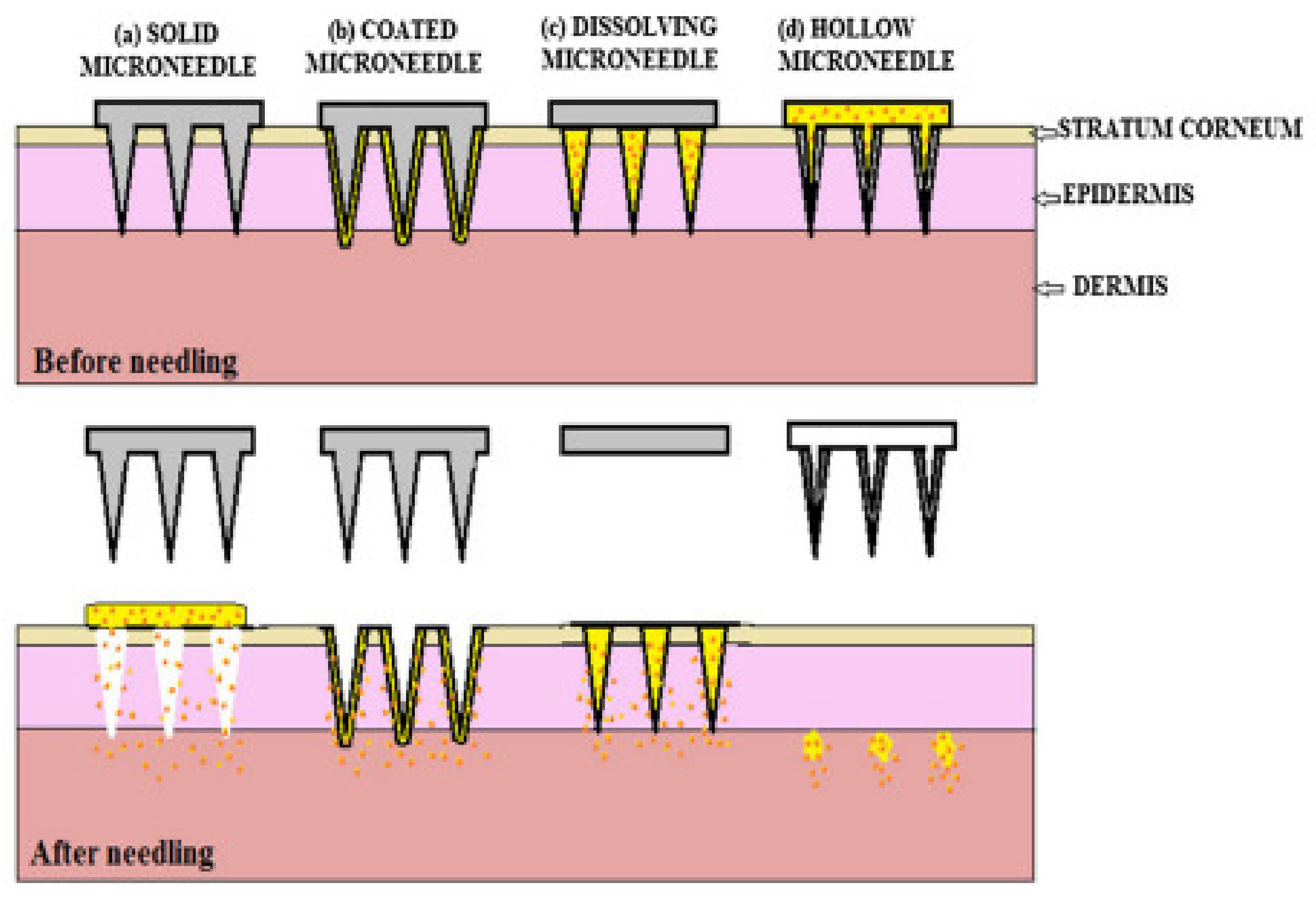
2.1. Solid MNs
2.2. Dissolving MNs
2.3. Coated MNs

| Sr. No. | Type of MNs | Material Used for Fabrication | Drug Delivery Approach | Benefits | Limitations |
|---|---|---|---|---|---|
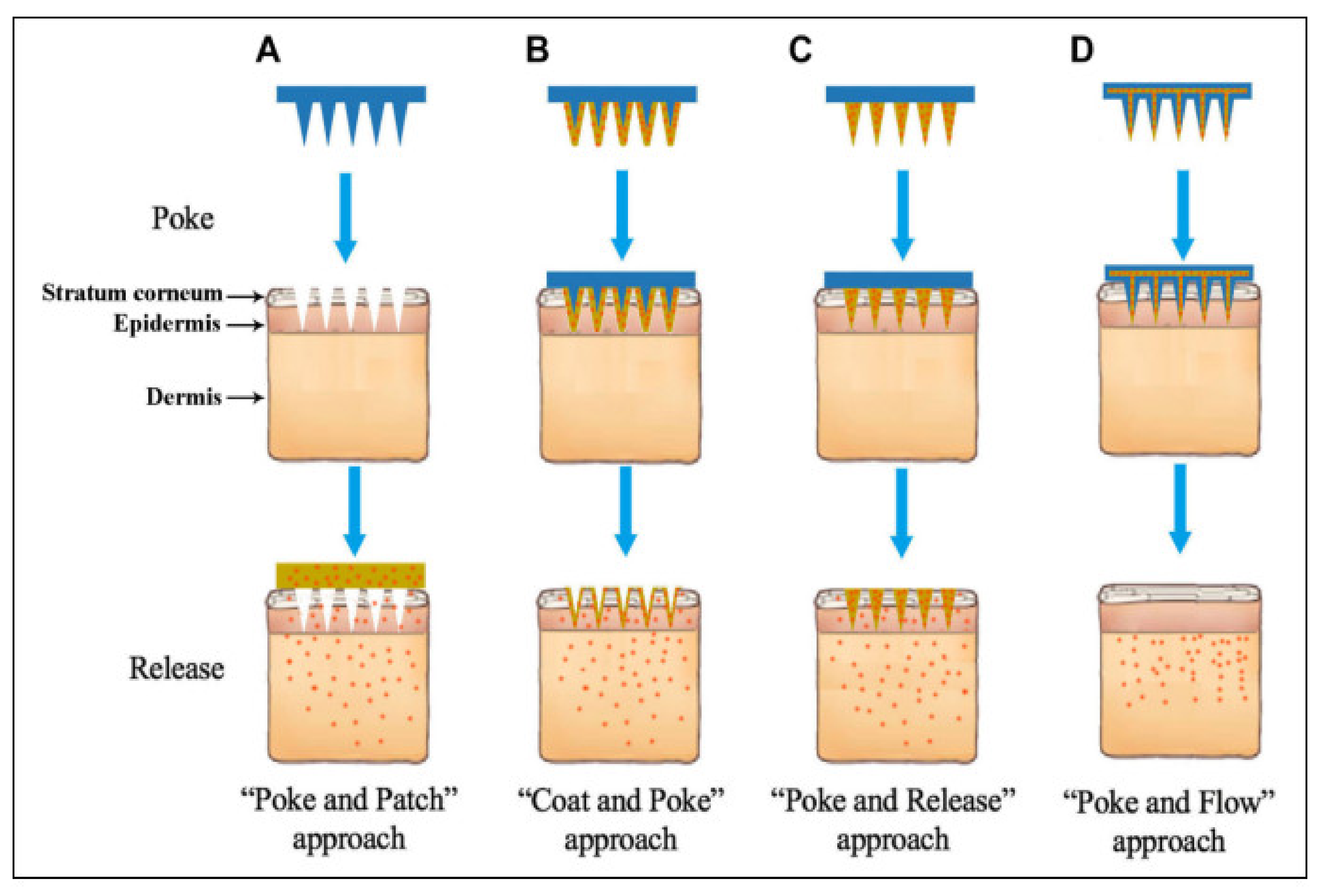
| 1. | Solid | Silicon, stainless steel, acrylic | Poke and Patch | High mechanical strength |
|
| 2. | Coated | Stainless steel, titanium, polymer | Coat and Poke |
|
|
| 3. | Dissolving/ Biodegradable | polyvinylpyrrolidone (PVP), carboxymethyl cellulose, sugar, dextran, polyvinyl alcohol (PVA), poly(lactic acid), chitosan, poly(glycolic acid), poly (lactide-co-glycolide) (PLGA) | Poke and Release |
|
|
| 4. | Hollow | Silicon, metal, glass, ceramic and polymers | Poke and Flow |
|
|
| 5. | Hydrogel forming | Chitosan, PVA, PLGA, poly(methyl vinyl ether-co- maleic acid) | Poke and Release |
|
|
2.4. Hydrogel Forming MNs
2.5. Hollow MNs
3. Material Used for Fabrication of MNs
3.1. Metal Material
3.2. Polymers
3.2.1. Biodegradable
3.2.2. Non-Biodegradable
3.2.3. Natural Polymers
3.3. Natural Polysaccharides for MNs
- (1)
- Hyaluronic acid MNs;
- (2)
- Chondroitin sulphate MNs;
- (3)
- Cellulose-based MNs;
- (4)
- Chitin and chitosan MNs;
- (5)
- Starch-based MNs.
3.3.1. Hyaluronic Acid MNs
3.3.2. Chondroitin Sulphate MNs
3.3.3. Cellulose-Based MNs
3.3.4. Chitin and Chitosan MNs
3.3.5. Starch-Based MN
4. Techniques of Preparation of MNs (MNs)
4.1. Microfabrication Basics
4.2. Thin Film Deposition
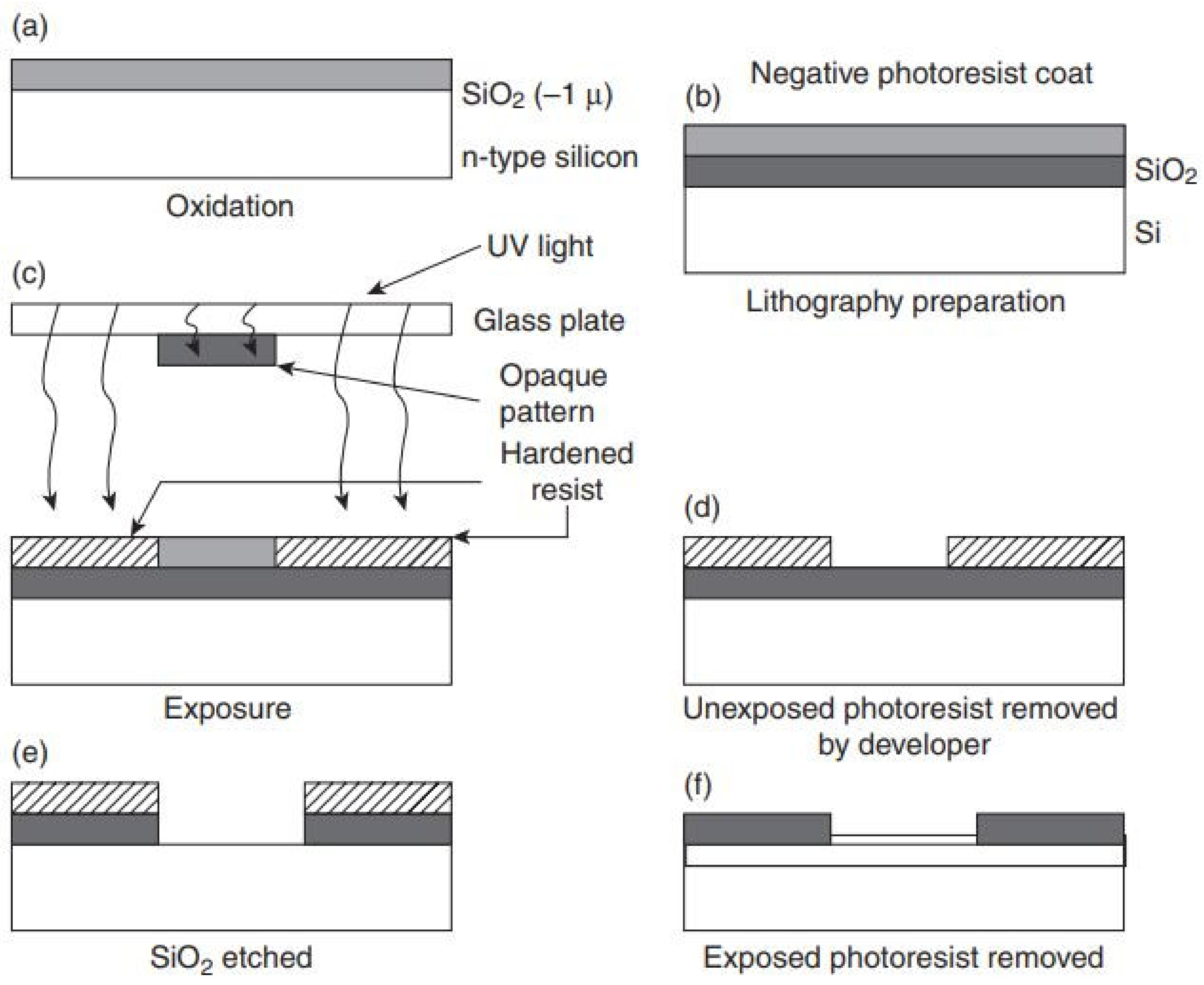
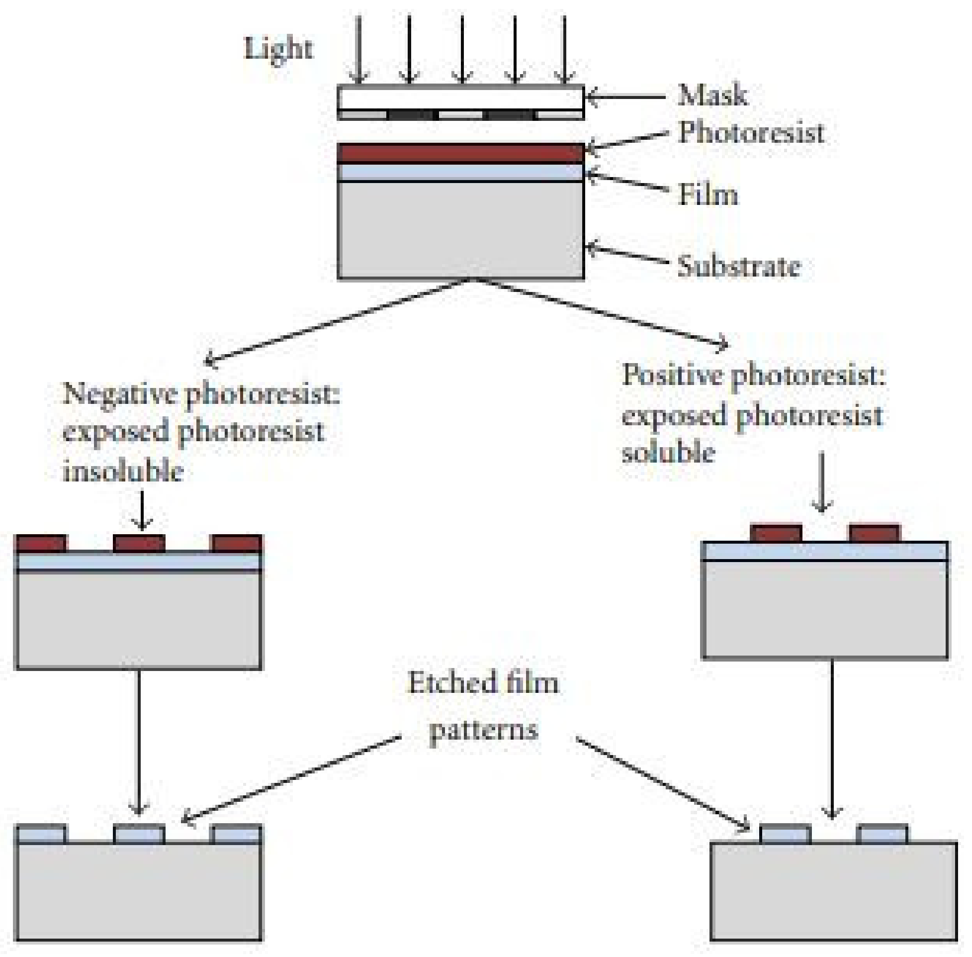
4.3. Photolithography
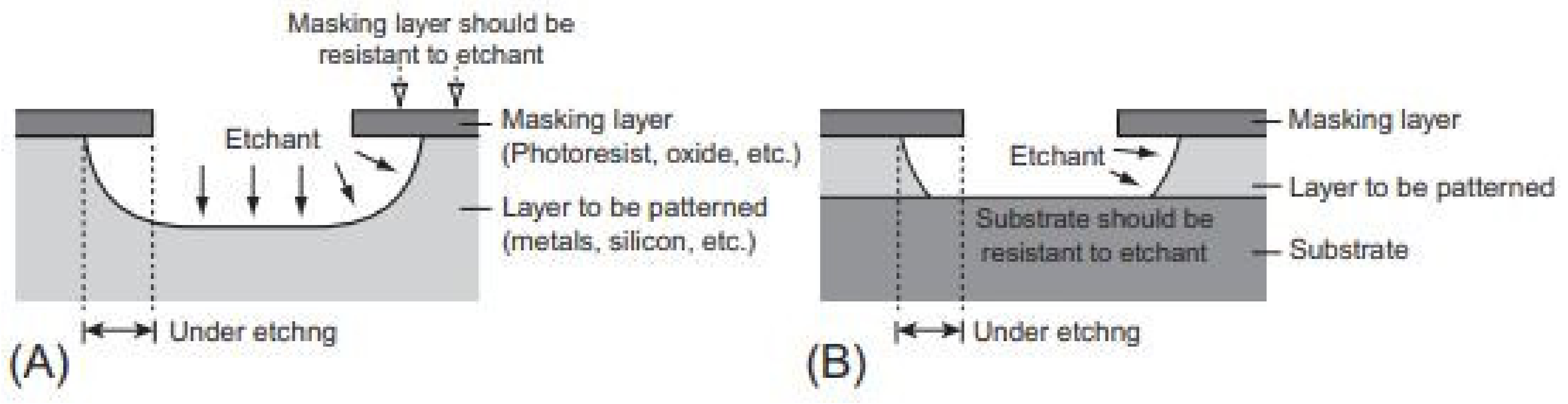
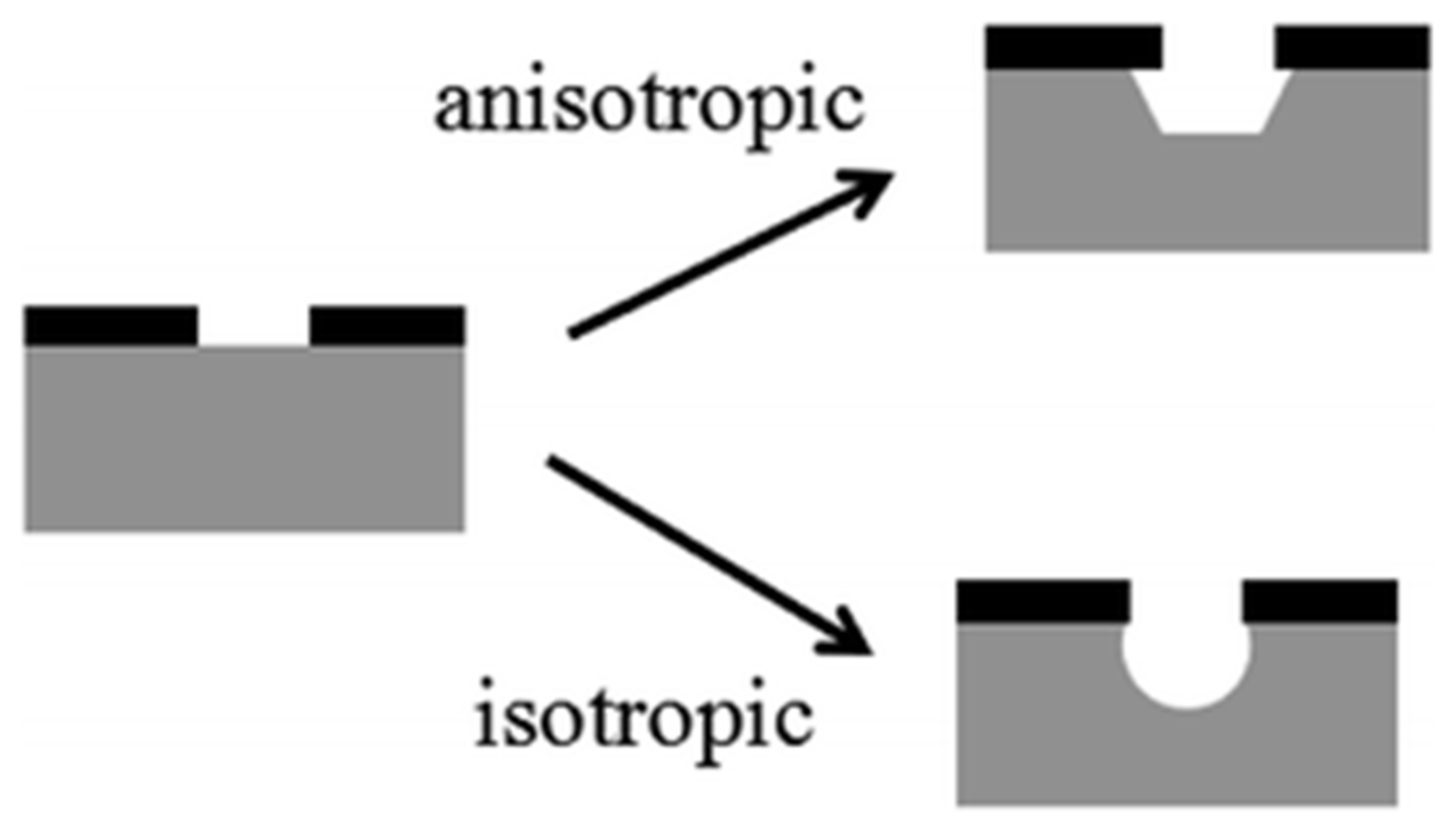
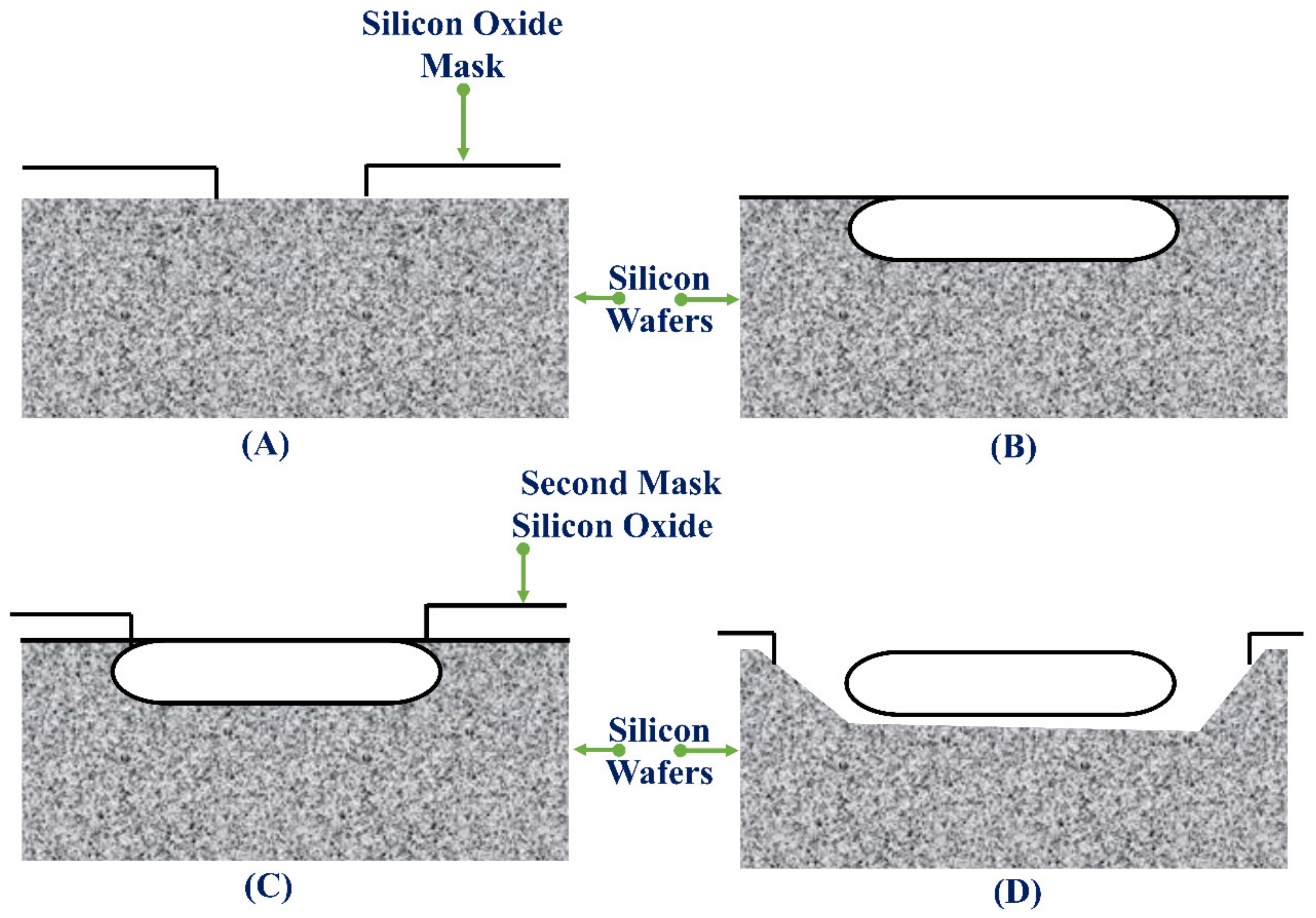
4.4. Etching
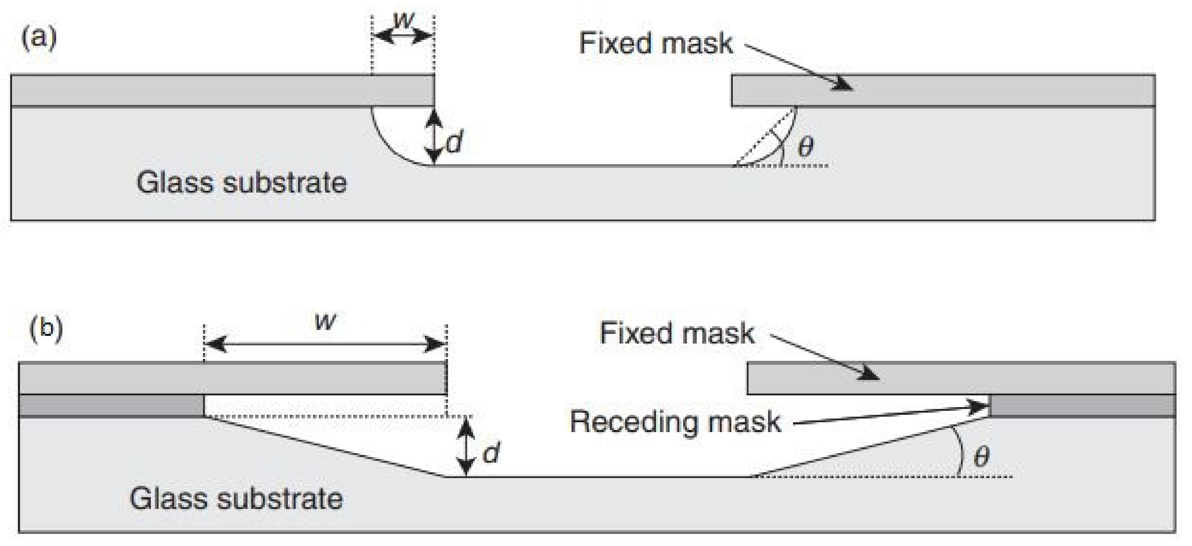
4.4.1. Wet Etching
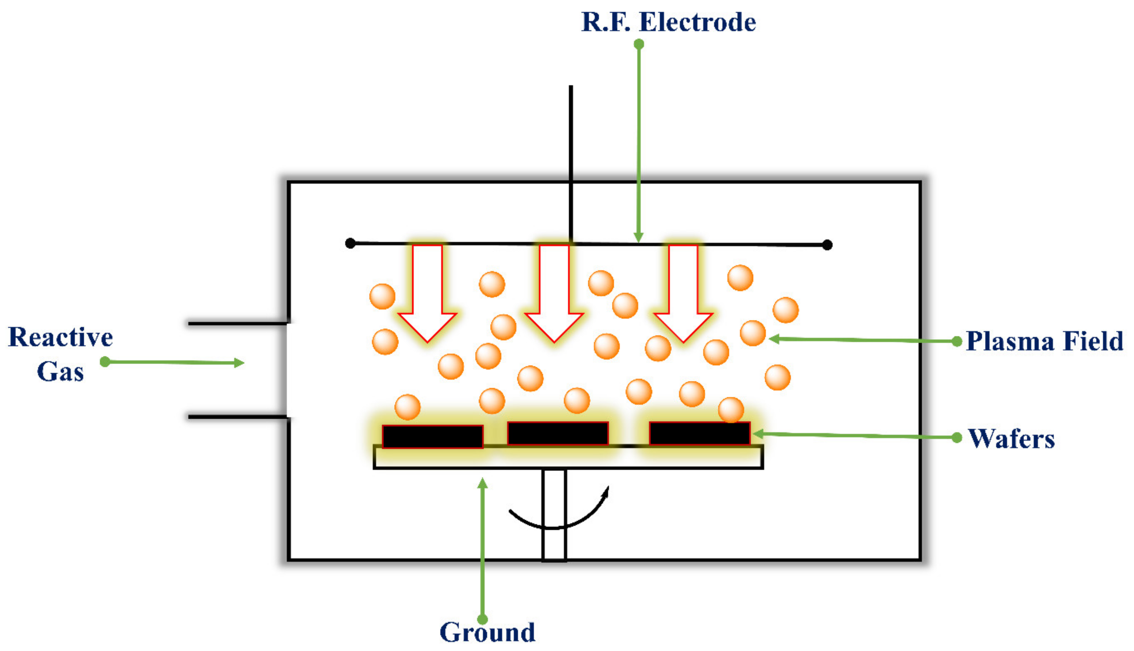
4.4.2. Dry Etching
4.4.3. Reactive Ion Etching (RIE)
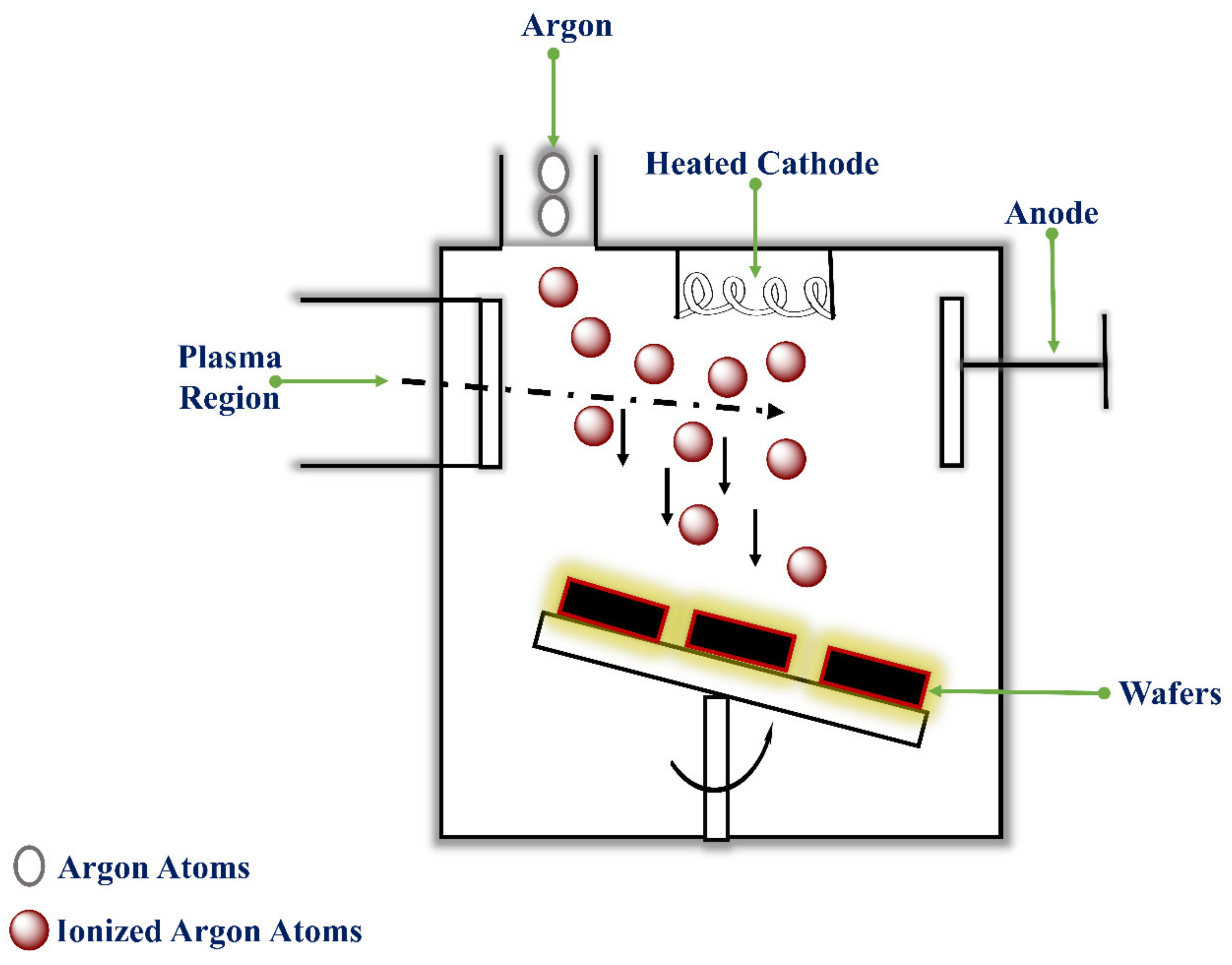
4.5. Ion-Beam Milling (IBM)
5. Characterization of MNs
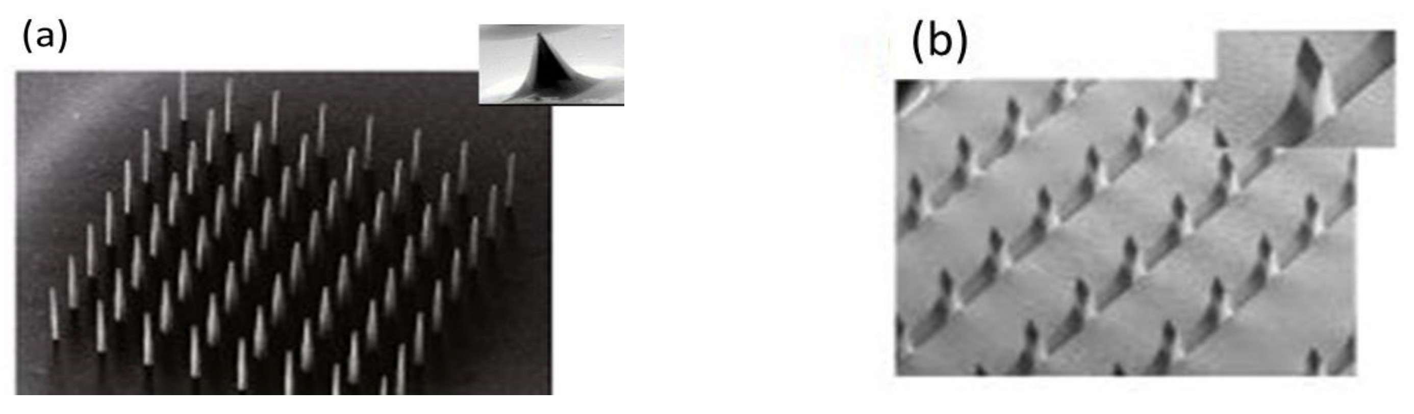
5.1. Morphology and Geometry
Scanning Electron Microscopy (SEM)
5.2. Mechanical Integrity
Thermogravimetric Analysis
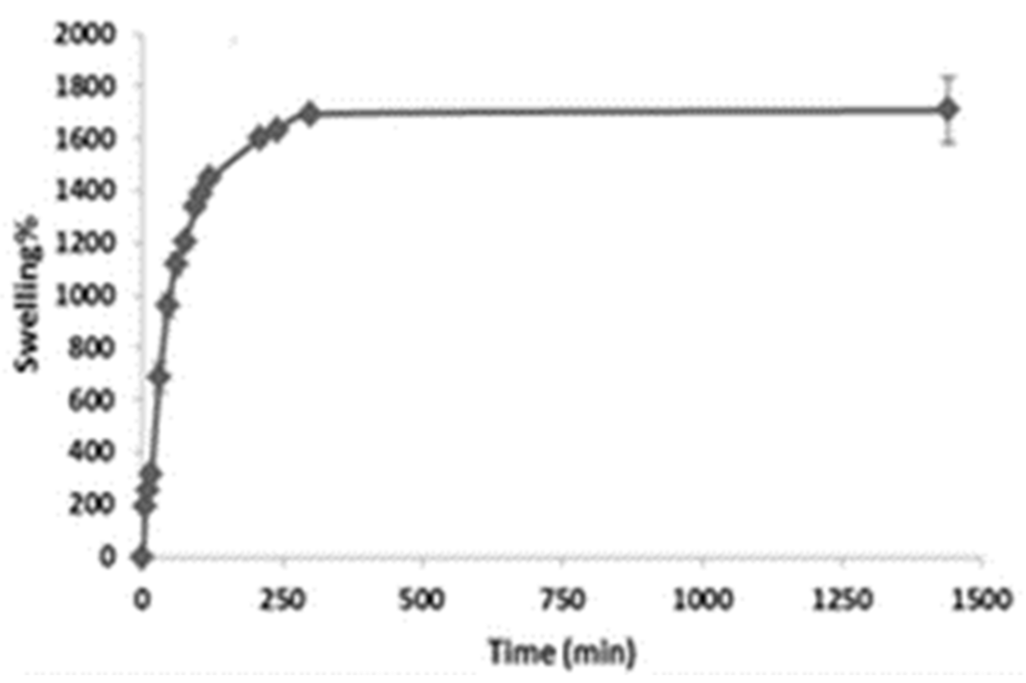
5.3. Swelling Property
5.4. Drug Release and Drug Distribution
6. Mechanical Properties of MNs
7. In Vitro and In Vivo Evaluations of MNs
7.1. In Vitro Studies
7.2. In Vivo Studies
8. Applications of MNs
8.1. Intradermal Drug Delivery through MNs Formulations
8.2. Small Molecules (Low Molecular Weight Drugs)
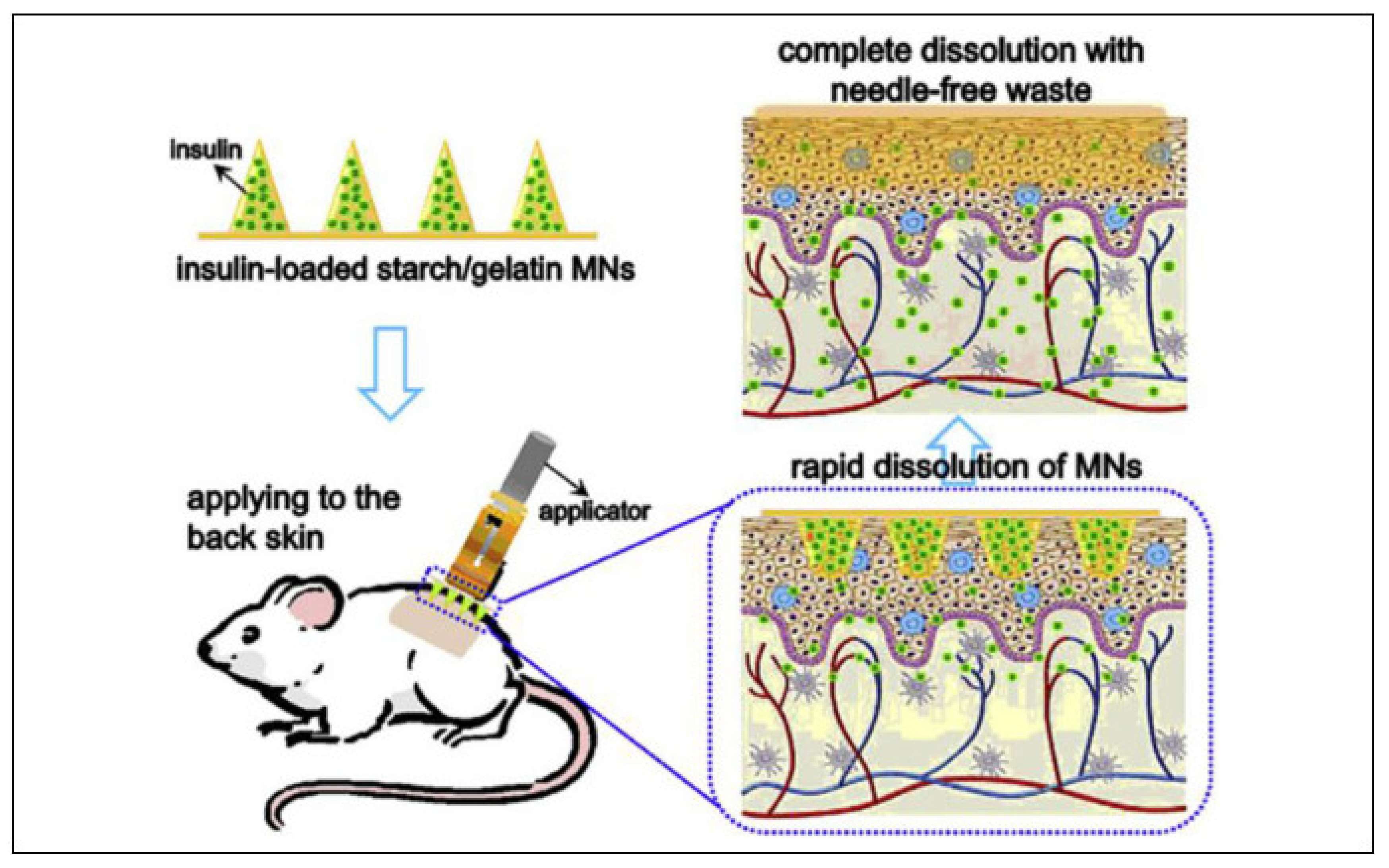
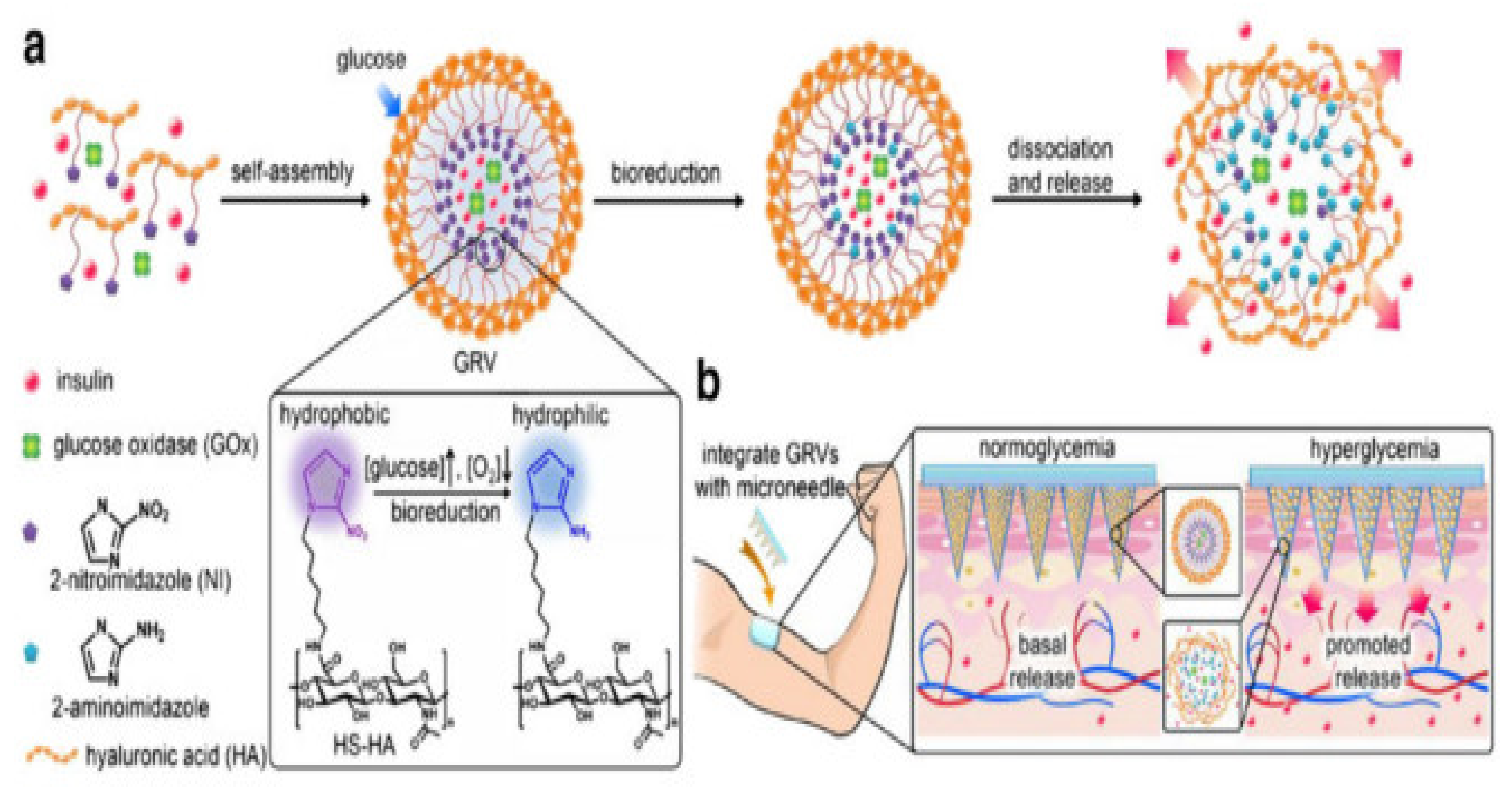
8.3. Large Molecules (Biotherapeutics)
8.4. Other Biomolecules
8.5. Vaccine
8.6. Diagnosis
8.7. Biosensing
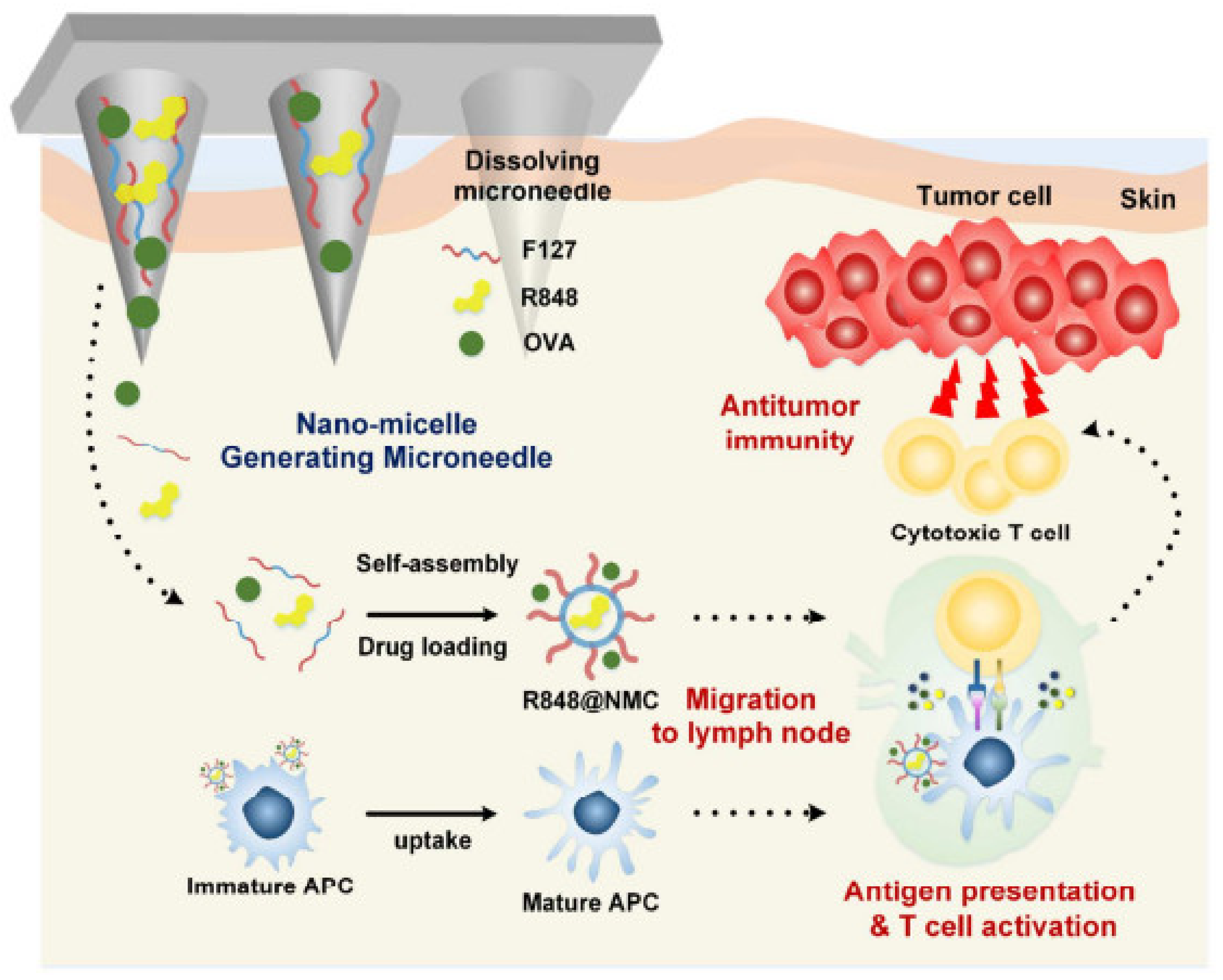
8.8. Cancer Therapy
8.9. Ocular Drug Delivery
9. Toxicity Study Methods
9.1. In Vitro Method
9.2. In Vivo Method
10. Regulatory Aspects
11. Patents
12. Conclusions
13. Future Scope
Author Contributions
Funding
Institutional Review Board Statement
Informed Consent Statement
Data Availability Statement
Acknowledgments
Conflicts of Interest
References
- Goldberg, M.; Gomez-Orellana, I. Challenges for the Oral Delivery of Macromolecules. Nat. Rev. Drug Discov. 2003, 2, 289–295. [Google Scholar] [CrossRef] [PubMed]
- Scheuplein, R.J.; Blank, I.H. Permeability of the Skin. Physiol. Rev. 1971, 51, 702–747. [Google Scholar] [CrossRef] [PubMed]
- Nazary Abrbekoh, F.; Salimi, L.; Saghati, S.; Amini, H.; Fathi Karkan, S.; Moharamzadeh, K.; Sokullu, E.; Rahbarghazi, R. Application of microneedle patches for drug delivery; doorstep to novel therapies. J. Tissue Eng. 2022, 13, 20417314221085390. [Google Scholar] [CrossRef] [PubMed]
- Donnelly, R.F.; Singh, T.R.R.; Woolfson, A.D. Microneedle-Based Drug Delivery Systems: Microfabrication, Drug Delivery, and Safety. Drug Deliv. 2010, 17, 187–207. [Google Scholar] [CrossRef] [Green Version]
- Donnelly, R.; Douroumis, D. Microneedles for Drug and Vaccine Delivery and Patient Monitoring. Drug Deliv. Transl. Res. 2015, 5, 311–312. [Google Scholar] [CrossRef] [Green Version]
- Aldawood, F.K.; Andar, A.; Desai, S. A Comprehensive Review of Microneedles: Types, Materials, Processes, Characterizations and Applications. Polymers 2021, 13, 2815. [Google Scholar] [CrossRef]
- Jakka, D.; Matadh, A.V.; Shivakumar, H.N.; Maibach, H.; Murthy, S.N. Polymer Coated Polymeric (PCP) microneedles for sampling of drugs and biomarkers from tissues. Eur. J. Pharm. Sci. 2022, 106203, in press. [Google Scholar] [CrossRef]
- Kim, Y.C.; Prausnitz, M.R. Enabling Skin Vaccination Using New Delivery Technologies. Drug Deliv. Transl. Res. 2011, 1, 7–12. [Google Scholar] [CrossRef] [Green Version]
- Kabir, M.T.; Ferdous Mitu, J.; Akter, R.; Akhtar, M.F.; Saleem, A.; Al-Harrasi, A.; Bhatia, S.; Rahman, M.S.; Damiri, F.; Berrada, M.; et al. Therapeutic Potential of Dopamine Agonists in the Treatment of Type 2 Diabetes Mellitus. Environ. Sci. Pollut. Res. 2022. [Google Scholar] [CrossRef]
- Vora, L.K.; Moffatt, K.; Tekko, I.A.; Paredes, A.J.; Volpe-Zanutto, F.; Mishra, D.; Peng, K.; Raj Singh Thakur, R.; Donnelly, R.F. Microneedle Array Systems for Long-Acting Drug Delivery. Eur. J. Pharm. Biopharm. 2021, 159, 44–76. [Google Scholar] [CrossRef]
- Zhang, W.; Zuo, H.; Cheng, Z.; Shi, Y.; Guo, Z.; Meng, N.; Thomas, A.; Liao, Y. Macroscale Conjugated Microporous Polymers: Controlling Versatile Functionalities over Several Dimensions. Adv. Mater. (Deerfield Beach Fla.) 2022, 34, e2104952. [Google Scholar] [CrossRef]
- Microneedle Technologies for (Trans) Dermal Drug and Vaccine Delivery. Available online: https://www.sciencedirect.com/science/article/abs/pii/S0168365912000740 (accessed on 30 March 2022).
- Nguyen, T.T.; Nguyen, T.T.D.; Tran, N.M.A.; Nguyen, H.T.; Vo, G.V. Microneedles Enable the Development of Skin-Targeted Vaccines against Coronaviruses and Influenza Viruses. Pharm. Dev. Technol. 2022, 27, 83–94. [Google Scholar] [CrossRef]
- Microneedles: A Smart Approach and Increasing Potential for Transdermal Drug Delivery System. Available online: https://www.sciencedirect.com/science/article/pii/S0753332218348091 (accessed on 8 March 2022).
- Li, J.; Xiang, H.; Zhang, Q.; Miao, X. Polysaccharide-Based Transdermal Drug Delivery. Pharmaceuticals 2022, 15, 602. [Google Scholar] [CrossRef]
- Benson, H.A.; Grice, J.E.; Mohammed, Y.; Namjoshi, S.; Roberts, M.S. Topical and Transdermal Drug Delivery: From Simple Potions to Smart Technologies. Curr. Drug Deliv. 2019, 16, 444–460. [Google Scholar] [CrossRef]
- Sachdeva, V.; Banga, A.K. Microneedles and Their Applications. Recent Pat. Drug Deliv. Formul. 2011, 5, 95–132. [Google Scholar] [CrossRef]
- Zhang, P.; Zhang, Y.; Liu, C.G. Polymeric Nanoparticles Based on Carboxymethyl Chitosan in Combination with Painless Microneedle Therapy Systems for Enhancing Transdermal Insulin Delivery. RSC Adv. 2020, 10, 24319–24329. [Google Scholar] [CrossRef]
- Yeo, L.Y.; Chang, H.C.; Chan, P.P.Y.; Friend, J.R. Microfluidic Devices for Bioapplications. Small 2011, 7, 12–48. [Google Scholar] [CrossRef]
- Ita, K. Transdermal Delivery of Drugs with Microneedles—Potential and Challenges. Pharmaceutics 2015, 7, 90–105. [Google Scholar] [CrossRef] [Green Version]
- Khandan, O.; Kahook, M.; Rao, M. Fenestrated Microneedles for Ocular Drug Delivery. Sens. Actuators B Chem. 2016, 223, 15–23. [Google Scholar] [CrossRef]
- Aditya, A. Optimization of Collagen Microneedle Using Taguchi Method; The University of Texas at El Paso: El Paso, TX, USA, 2017. [Google Scholar]
- Pendse, P.A. Skin Response to Immunogenic and non Immunogenic Material as Applied to Vaccine Delivery and Reconstructive Surgery; Mercer University: Macon, GA, USA, 2006. [Google Scholar]
- Gao, N.; Zhu, J.L.; Su, A.L.; Kou, L.L.; Liu, Z. Five-in-one: A novel, cost-effective yet simple use of micro needle holder. Int. J. Ophthalmol. 2022, 15, 657–660. [Google Scholar] [CrossRef]
- Donnelly, R.F.; Singh, T.R.R.; Larrañeta, E.; McCrudden, M.T. Microneedles for Drug and Vaccine Delivery and Patient Monitoring; John Wiley & Sons: Hoboken, NJ, USA, 2018. [Google Scholar]
- Microneedle, Bio-Microneedle and Bio-Inspired Microneedle: A Review. Available online: https://www.sciencedirect.com/science/article/abs/pii/S0168365917300627 (accessed on 30 March 2022).
- Monitoring the Penetration Process of Single Microneedles with Varying Tip Diameters. Available online: https://www.sciencedirect.com/science/article/pii/S1751616114002999 (accessed on 30 March 2022).
- Shravanth, S.H.; Osmani, R.A.M.; Anupama, V.P.; Rahamathulla, M.; Gangadharappa, H.V. Microneedles-Based Drug Delivery for the Treatment of Psoriasis. J. Drug Deliv. Sci. Technol. 2021, 64, 102668. [Google Scholar] [CrossRef]
- Díaz-Gómez, L.; Concheiro, A.; Alvarez-Lorenzo, C. Polymers in Drug Delivery: Fundamentals. In Advanced Polymers in Medicine; Puoci, F., Ed.; Springer International Publishing: Cham, Switzerland, 2015; pp. 319–339. ISBN 978-3-319-12478-0. [Google Scholar]
- Nagarkar, R.; Singh, M.; Nguyen, H.X.; Jonnalagadda, S. A Review of Recent Advances in Microneedle Technology for Transdermal Drug Delivery. J. Drug Deliv. Sci. Technol. 2020, 59, 101923. [Google Scholar] [CrossRef]
- Miyano, T.; Tobinaga, Y.; Kanno, T.; Matsuzaki, Y.; Takeda, H.; Wakui, M.; Hanada, K. Sugar Micro Needles as Transdermic Drug Delivery System. Biomed. Microdevices 2005, 7, 185–188. [Google Scholar] [CrossRef]
- Lagreca, E.; Onesto, V.; Di Natale, C.; La Manna, S.; Netti, P.A.; Vecchione, R. Recent Advances in the Formulation of PLGA Microparticles for Controlled Drug Delivery. Prog. Biomater. 2020, 9, 153–174. [Google Scholar] [CrossRef]
- Dissolving Polymeric Microneedle Arrays for Electrically Assisted Transdermal Drug Delivery. Available online: https://www.sciencedirect.com/science/article/abs/pii/S0168365912000089 (accessed on 7 March 2022).
- Rodgers, A.M.; Cordeiro, A.S.; Donnelly, R.F. Technology Update: Dissolvable Microneedle Patches for Vaccine Delivery. Med. Devices (Auckl) 2019, 12, 379–398. [Google Scholar] [CrossRef] [Green Version]
- Leone, M.; Mönkäre, J.; Bouwstra, J.A.; Kersten, G. Dissolving Microneedle Patches for Dermal Vaccination. Pharm. Res. 2017, 34, 2223–2240. [Google Scholar] [CrossRef] [Green Version]
- Damiri, F.; Kommineni, N.; Ebhodaghe, S.O.; Bulusu, R.; Jyothi, V.G.S.; Sayed, A.A.; Awaji, A.A.; Germoush, M.O.; Al-Malky, H.S.; Nasrullah, M.Z. Microneedle-Based Natural Polysaccharide for Drug Delivery Systems (DDS): Progress and Challenges. Pharmaceuticals 2022, 15, 190. [Google Scholar] [CrossRef]
- Cavalu, S.; Ratiu, C.; Ponta, O.; Simon, V.; Rugina, D.; Miclaus, V.; Akin, I.; Goller, G. Improving osseointegration of alumina/zirconia ceramic implants by fluoride surface treatment. Dig. J. Nanomater. Biostruct. 2014, 9, 797–808. [Google Scholar]
- Swathi, H.P.; Anusha Matadh, V.; Paul Guin, J.; Narasimha Murthy, S.; Kanni, P.; Varshney, L.; Suresh, S.; Shivakumar, H.N. Effect of Gamma Sterilization on the Properties of Microneedle Array Transdermal Patch System. Drug Dev. Ind. Pharm. 2020, 46, 606–620. [Google Scholar] [CrossRef]
- Giri Nandagopal, M.S.; Antony, R.; Rangabhashiyam, S.; Sreekumar, N.; Selvaraju, N. Overview of Microneedle System: A Third Generation Transdermal Drug Delivery Approach. Microsyst. Technol. 2014, 20, 1249–1272. [Google Scholar] [CrossRef]
- Cormier, M.; Johnson, B.; Ameri, M.; Nyam, K.; Libiran, L.; Zhang, D.D.; Daddona, P. Transdermal Delivery of Desmopressin Using a Coated Microneedle Array Patch System. J. Control. Release 2004, 97, 503–511. [Google Scholar] [CrossRef]
- Chong, R.H.E.; Gonzalez-Gonzalez, E.; Lara, M.F.; Speaker, T.J.; Contag, C.H.; Kaspar, R.L.; Coulman, S.A.; Hargest, R.; Birchall, J.C. Gene Silencing Following SiRNA Delivery to Skin via Coated Steel Microneedles: In Vitro and in Vivo Proof-of-Concept. J. Control. Release 2013, 166, 211–219. [Google Scholar] [CrossRef] [PubMed] [Green Version]
- Prausnitz, M.R. Microneedles for Transdermal Drug Delivery. Adv. Drug Deliv. Rev. 2004, 56, 581–587. [Google Scholar] [CrossRef] [PubMed]
- Boehm, R.D.; Daniels, J.; Stafslien, S.; Nasir, A.; Lefebvre, J.; Narayan, R.J. Polyglycolic Acid Microneedles Modified with Inkjet-Deposited Antifungal Coatings. Biointerphases 2015, 10, 011004. [Google Scholar] [CrossRef] [Green Version]
- Sharma, S.; Hatware, K.; Bhadane, P.; Sindhikar, S.; Mishra, D.K. Recent Advances in Microneedle Composites for Biomedical Applications: Advanced Drug Delivery Technologies. Mater. Sci. Eng. C 2019, 103, 109717. [Google Scholar] [CrossRef]
- Donnelly, R.F.; McCrudden, M.T.C.; Alkilani, A.Z.; Larrañeta, E.; McAlister, E.; Courtenay, A.J.; Kearney, M.C.; Raj Singh, T.R.; McCarthy, H.O.; Kett, V.L.; et al. Hydrogel-Forming Microneedles Prepared from “Super Swelling” Polymers Combined with Lyophilised Wafers for Transdermal Drug Deliqvery. PLoS ONE 2014, 9, e111547. [Google Scholar] [CrossRef]
- Griss, P.; Stemme, G. Side-Opened out-of-Plane Microneedles for Microfluidic Transdermal Liquid Transfer. J. Microelectromechanical Syst. 2003, 12, 296–301. [Google Scholar] [CrossRef]
- Nawar, A.E. Modified Microneedle for Suprachoroidal Injection of Triamcinolone Acetonide Combined with Intravitreal Injection of Ranibizumab in Branch Retinal Vein Occlusion Patients. Clin. Ophthalmol. 2022, 16, 1139–1151. [Google Scholar] [CrossRef]
- Raghu, T.; Singh, R.; Mccarron, P.A.; Woolfson, A.D.; Donnelly, R.F. Investigation of Swelling and Network Parameters of Poly (Ethylene Glycol)-Crosslinked Poly (Methyl Vinyl Ether-Co-Maleic Acid) Hydrogels. Eur. Polym. J. 2009, 45, 1239–1249. [Google Scholar] [CrossRef]
- Karelin, A.M.; Orekhov, Y.D.; Luchinin, V.V.; Gareev, K.G.; Khmelnitskiy, I.K.; Testov, D.O. Development of a Modular Reconfigurable Mold for Prototyping of Hollow Microneedles. In Proceedings of the 2022 Conference of Russian Young Researchers in Electrical and Electronic Engineering (ElConRus), St. Petersburg, Russia, 25–28 January 2022; pp. 1531–1533. [Google Scholar]
- Mishra, R.; Maiti, T.K.; Bhattacharyya, T.K. Development of SU-8 Hollow Microneedles on a Silicon Substrate with Microfluidic Interconnects for Transdermal Drug Delivery. J. Micromech. Microeng. 2018, 28, 105017. [Google Scholar] [CrossRef]
- Makvandi, P.; Kirkby, M.; Hutton, A.R.J.; Shabani, M.; Yiu, C.K.Y.; Baghbantaraghdari, Z.; Jamaledin, R.; Carlotti, M.; Mazzolai, B.; Mattoli, V.; et al. Engineering Microneedle Patches for Improved Penetration: Analysis, Skin Models and Factors Affecting Needle Insertion. Nano-Micro Lett. 2021, 13, 93. [Google Scholar] [CrossRef]
- Kumar, V.; Pallapa, M.; Rezai, P.; Selvaganapathy, P.R. Polymers. Ref. Modul. Mater. Sci. Mater. Eng. 2016. [Google Scholar] [CrossRef]
- Jiang, J.; Moore, J.S.; Edelhauser, H.F.; Prausnitz, M.R. Intrascleral Drug Delivery to the Eye Using Hollow Microneedles. Pharm. Res. 2009, 26, 395–403. [Google Scholar] [CrossRef]
- Anand, P.; Tripathi, N. A Procedural Excursion of Micro Needles for Drug Delivery Systems. Micro Nanosyst. 2020, 12, 232–239. [Google Scholar] [CrossRef]
- 3D-Printed Microneedles in Biomedical Applications. Available online: https://www.sciencedirect.com/science/article/pii/S2589004220312098 (accessed on 31 March 2022).
- He, X.; Sun, J.; Zhuang, J.; Xu, H.; Liu, Y.; Wu, D. Microneedle System for Transdermal Drug and Vaccine Delivery: Devices, Safety, and Prospects. Dose-Response 2019, 17, 1559325819878585. Available online: https://journals.sagepub.com/doi/10.1177/1559325819878585 (accessed on 31 March 2022). [CrossRef] [Green Version]
- Iliescu, F.; Dumitrescu-Ionescu, D.; Petrescu, M.; Iliescu, C. A Review on Transdermal Drug Delivery Using Microneedles: Current Research and Perspective. Ann. Acad. Rom. Sci. Ser. Sci. Technol. Inf. 2014, 7, 734. [Google Scholar]
- Bhatnagar, S.; Gadeela, P.R.; Thathireddy, P.; Venuganti, V.V.K. Microneedle-Based Drug Delivery: Materials of Construction. J. Chem. Sci. 2019, 131, 90. [Google Scholar] [CrossRef] [Green Version]
- Gill, H.S.; Prausnitz, M.R. Coated Microneedles for Transdermal Delivery. J. Control. Release 2007, 117, 227–237. [Google Scholar] [CrossRef] [Green Version]
- Kim, Y.C.; Park, J.H.; Prausnitz, M.R. Microneedles for Drug and Vaccine Delivery. Adv. Drug Deliv. Rev. 2012, 64, 1547–1568. [Google Scholar] [CrossRef] [Green Version]
- Kim, Y.C.; Quan, F.S.; Compans, R.W.; Kang, S.M.; Prausnitz, M.R. Formulation and Coating of Microneedles with Inactivated Influenza Virus to Improve Vaccine Stability and Immunogenicity. J. Control. Release 2010, 142, 187–195. [Google Scholar] [CrossRef] [Green Version]
- Choi, H.J.; Bondy, B.J.; Yoo, D.G.; Compans, R.W.; Kang, S.M.; Prausnitz, M.R. Stability of Whole Inactivated Influenza Virus Vaccine during Coating onto Metal Microneedles. J. Control. Release 2013, 166, 159–171. [Google Scholar] [CrossRef] [Green Version]
- Ita, K. Transdermal Delivery of Drugs with Microneedles: Strategies and Outcomes. J. Drug Deliv. Sci. Technol. 2015, 29, 16–23. [Google Scholar] [CrossRef]
- Amarnani, R.; Shende, P. Microneedles in diagnostic, treatment and theranostics: An advancement in minimally-invasive delivery system. Biomed Microdevices. 2021, 24, 4. [Google Scholar] [CrossRef]
- Ahmed Saeed AL-Japairai, K.; Mahmood, S.; Hamed Almurisi, S.; Reddy Venugopal, J.; Rebhi Hilles, A.; Azmana, M.; Raman, S. Current Trends in Polymer Microneedle for Transdermal Drug Delivery. Int. J. Pharm. 2020, 587, 119673. [Google Scholar] [CrossRef]
- Pawley, D.C.; Goncalves, S.; Bas, E.; Dikici, E.; Deo, S.K.; Daunert, S.; Telischi, F. Dexamethasone (DXM)-Coated Poly(Lactic-Co-Glycolic Acid) (PLGA) Microneedles as an Improved Drug Delivery System for Intracochlear Biodegradable Devices. Adv. Ther. 2021, 4, 2100155. [Google Scholar] [CrossRef]
- Wu, L.; Shrestha, P.; Iapichino, M.; Cai, Y.; Kim, B.; Stoeber, B. Characterization Method for Calculating Diffusion Coefficient of Drug from Polylactic Acid (PLA) Microneedles into the Skin. J. Drug Deliv. Sci. Technol. 2021, 61, 102192. [Google Scholar] [CrossRef]
- Li, X.; Xu, Q.; Wang, J.; Zhang, P.; Wang, Y.; Ji, J. A Gene-Coated Microneedle Patch Based on Industrialized Ultrasonic Spraying Technology with a Polycation Vector to Improve Antitumor Efficacy. J. Mater. Chem. B 2021, 9, 5528–5536. [Google Scholar] [CrossRef] [PubMed]
- Epigallocatechin Gallate/L-Ascorbic Acid–Loaded Poly-γ-Glutamate Microneedles with Antioxidant, Anti-Inflammatory, and Immunomodulatory Effects for the Treatment of Atopic Dermatitis. Available online: https://www.sciencedirect.com/science/article/abs/pii/S1742706121003421 (accessed on 7 April 2022).
- Saha, I.; Rai, V.K. Hyaluronic Acid Based Microneedle Array: Recent Applications in Drug Delivery and Cosmetology. Carbohydr. Polym. 2021, 267, 118168. [Google Scholar] [CrossRef] [PubMed]
- Zare, M.R.; Khorram, M.; Barzegar, S.; Sarkari, B.; Asgari, Q.; Ahadian, S.; Zomorodian, K. Dissolvable Carboxymethyl Cellulose/Polyvinylpyrrolidone Microneedle Arrays for Transdermal Delivery of Amphotericin B to Treat Cutaneous Leishmaniasis. Int. J. Biol. Macromol. 2021, 182, 1310–1321. [Google Scholar] [CrossRef] [PubMed]
- Zhang, X.P.; Wang, B.B.; Li, W.X.; Fei, W.M.; Cui, Y.; Guo, X.D. In Vivo Safety Assessment, Biodistribution and Toxicology of Polyvinyl Alcohol Microneedles with 160-Day Uninterruptedly Applications in Mice. Eur. J. Pharm. Biopharm. 2021, 160, 1–8. [Google Scholar] [CrossRef] [PubMed]
- Lu, X.; Sun, Y.; Han, M.; Chen, D.; Wang, A.; Sun, K. Silk Fibroin Double-Layer Microneedles for the Encapsulation and Controlled Release of Triptorelin. Int. J. Pharm. 2022, 613, 121433. [Google Scholar] [CrossRef]
- Zhou, Z.; Xing, M.; Zhang, S.; Yang, G.; Gao, Y. Process Optimization of Ca2+ Cross-Linked Alginate-Based Swellable Microneedles for Enhanced Transdermal Permeability: More Applicable to Acidic Drugs. Int. J. Pharm. 2022, 618, 121669. [Google Scholar] [CrossRef]
- Yu, X.; Wang, C.; Wang, Y.; Li, L.; Gao, X.; Zhu, T.; An, P.; Meng, Z.; Wang, W.; Wu, T.; et al. Microneedle Array Patch Made of Kangfuxin/Chitosan/Fucoidan Complex Enables Full-Thickness Wound Healing. Front. Chem. 2022, 10, 838920. [Google Scholar] [CrossRef]
- Nguyen, T.T.; Nguyen, T.T.D.; Tran, N.M.A.; Vo, G.V. Advances of Microneedles in Hormone Delivery. Biomed. Pharmacother. 2022, 145, 112393. [Google Scholar] [CrossRef]
- Azmana, M.; Mahmood, S.; Hilles, A.R.; Mandal, U.K.; Saeed Al-Japairai, K.A.; Raman, S. Transdermal Drug Delivery System through Polymeric Microneedle: A Recent Update. J. Drug Deliv. Sci. Technol. 2020, 60, 101877. [Google Scholar] [CrossRef]
- Martin, C.J.; Allender, C.J.; Brain, K.R.; Morrissey, A.; Birchall, J.C. Low Temperature Fabrication of Biodegradable Sugar Glass Microneedles for Transdermal Drug Delivery Applications. J. Control. Release 2012, 158, 93–101. [Google Scholar] [CrossRef]
- Thakor, N.; Lütke-Eversloh, T.; Steinbüchel, A. Application of the BPEC Pathway for Large-Scale Biotechnological Production of Poly(3-Mercaptopropionate) by Recombinant Escherichia Coli, Including a Novel in Situ Isolation Method. Appl. Environ. Microbiol. 2005, 71, 835–841. [Google Scholar] [CrossRef] [Green Version]
- Iwata, S.; Toshima, K.; Matsumura, S. Enzyme-Catalyzed Preparation of Aliphatic Polyesters Containing Thioester Linkages. Macromol. Rapid Commun. 2003, 24, 467–471. [Google Scholar] [CrossRef]
- Hakkarainen, M.; Albertsson, A.C. Environmental Degradation of Polyethylene. Adv. Polym. Sci. 2004, 169, 177–199. [Google Scholar] [CrossRef]
- Rose, K.; Steinbüchel, A. Biodegradation of Natural Rubber and Related Compounds: Recent Insights into a Hardly Understood Catabolic Capability of Microorganisms. Appl. Environ. Microbiol. 2005, 71, 2803–2812. [Google Scholar] [CrossRef] [Green Version]
- Steinbüchel, A. Non-Biodegradable Biopolymers from Renewable Resources: Perspectives and Impacts. Curr. Opin. Biotechnol. 2005, 16, 607–613. [Google Scholar] [CrossRef]
- Cavalu, S.; Bisboaca, S.; Mates, I.M.; Pasca, P.M.; Laslo, V.; Costea, T.; Fritea, L.; Vicas, S. Novel Formulation Based on Chitosan-Arabic Gum Nanoparticles Entrapping Propolis Extract. Production, physico-chemical and structural characterization. Rev. Chim. 2018, 69, 3756–3760. [Google Scholar] [CrossRef]
- Antonescu, A.I.; Miere, F.; Fritea, L.; Ganea, M.; Zdrinca, M.; Dobjanschi, L.; Antonescu, A.; Vicas, S.I.; Bodog, F.; Sindhu, R.K.; et al. Perspectives on the Combined Effects of Ocimum Basilicum and Trifolium Pratense Extracts in Terms of Phytochemical Profile and Pharmacological Effects. Plants 2021, 10, 1390. [Google Scholar] [CrossRef]
- Ray, S.; Wirth, D.M.; Ortega-Rivera, O.A.; Steinmetz, N.F.; Pokorski, J.K. Dissolving Microneedle Delivery of a Prophylactic HPV Vaccine. Biomacromolecules 2022, 23, 903–912. [Google Scholar] [CrossRef]
- Qi, X.; Tong, X.; Pan, W.; Zeng, Q.; You, S.; Shen, J. Recent Advances in Polysaccharide-Based Adsorbents for Wastewater Treatment. J. Clean. Prod. 2021, 315, 128221. [Google Scholar] [CrossRef]
- Tong, X.; Pan, W.; Su, T.; Zhang, M.; Dong, W.; Qi, X. Recent Advances in Natural Polymer-Based Drug Delivery Systems. React. Funct. Polym. 2020, 148, 104501. [Google Scholar] [CrossRef]
- Qi, X.; Pan, W.; Tong, X.; Gao, T.; Xiang, Y.; You, S.; Mao, R.; Chi, J.; Hu, R.; Zhang, W.; et al. Ε-Polylysine-Stabilized Agarose/Polydopamine Hydrogel Dressings with Robust Photothermal Property for Wound Healing. Carbohydr. Polym. 2021, 264, 118046. [Google Scholar] [CrossRef]
- Kutbi, H.I.; Asfour, H.Z.; Kammoun, A.K.; Sirwi, A.; Cavalu, S.; Gad, H.A. Optimization of Hyaluronate-Based Liposomes to Augment the Oral Delivery and the Bioavailability of Berberine. Materials 2021, 14, 5759. [Google Scholar] [CrossRef]
- Zhu, J.; Dong, L.; Du, H.; Mao, J.; Xie, Y.; Wang, H.; Lan, J.; Lou, Y.; Fu, Y.; Wen, J.; et al. 5-Aminolevulinic Acid-Loaded Hyaluronic Acid Dissolving Microneedles for Effective Photodynamic Therapy of Superficial Tumors with Enhanced Long-Term Stability. Adv. Healthc. Mater. 2019, 8, 1900896. [Google Scholar] [CrossRef]
- Xu, Q.; Li, X.; Zhang, P.; Wang, Y. Rapidly Dissolving Microneedle Patch for Synergistic Gene and Photothermal Therapy of Subcutaneous Tumor. J. Mater. Chem. B 2020, 8, 4331–4339. [Google Scholar] [CrossRef]
- Hao, Y.; Chen, Y.; He, X.; Yang, F.; Han, R.; Yang, C.; Li, W.; Qian, Z. Near-Infrared Responsive 5-Fluorouracil and Indocyanine Green Loaded MPEG-PCL Nanoparticle Integrated with Dissolvable Microneedle for Skin Cancer Therapy. Bioact. Mater. 2020, 5, 542–552. [Google Scholar] [CrossRef] [PubMed]
- Hao, Y.; Li, W.; Zhou, X.; Yang, F.; Qian, Z. Microneedles-Based Transdermal Drug Delivery Systems: A Review. J. Biomed. Nanotechnol. 2017, 13, 1581–1597. [Google Scholar] [CrossRef] [PubMed]
- Fukushima, K.; Ise, A.; Morita, H.; Hasegawa, R.; Ito, Y.; Sugioka, N.; Takada, K. Two-Layered Dissolving Microneedles for Percutaneous Delivery of Peptide/Protein Drugs in Rats. Pharm. Res. 2011, 28, 7–21. [Google Scholar] [CrossRef] [PubMed]
- Poirier, D.; Renaud, F.; Dewar, V.; Strodiot, L.; Wauters, F.; Janimak, J.; Shimada, T.; Nomura, T.; Kabata, K.; Kuruma, K.; et al. Hepatitis B Surface Antigen Incorporated in Dissolvable Microneedle Array Patch Is Antigenic and Thermostable. Biomaterials 2017, 145, 256–265. [Google Scholar] [CrossRef] [PubMed]
- Shokri, J.; Adibkia, K. Application of Cellulose and Cellulose Derivatives in Pharmaceutical Industries; IntechOpen: London, UK, 2013; ISBN 978-953-51-1191-7. [Google Scholar]
- Falo, L.D., Jr.; Erdos, G.; Ozdoganlar, O.B. Microneedle Arrays for Cancer Therapy Applications. Patent 14/934,927, 19 May 2016. [Google Scholar]
- Lan, X.; Zhu, W.; Huang, X.; Yu, Y.; Xiao, H.; Jin, L.; Jane Pu, J.; Xie, X.; She, J.; Yan Lui, V.W.; et al. Microneedles Loaded with Anti-PD-1–Cisplatin Nanoparticles for Synergistic Cancer Immuno-Chemotherapy. Nanoscale 2020, 12, 18885–18898. [Google Scholar] [CrossRef]
- Ye, C.; Zhang, R. Semiconductor Microneedle Assembly Based on Gene Therapy, Manufacturing Method and Manufacturing Mold. Chinese Patent CN106426729A, 17 February 2022. [Google Scholar]
- Bacterial Nanocellulose-Hyaluronic Acid Microneedle Patches for Skin Applications: In Vitro and in Vivo Evaluation. Available online: https://www.sciencedirect.com/science/article/pii/S0928493120332689 (accessed on 8 March 2022).
- Chen, M.C.; Huang, S.F.; Lai, K.Y.; Ling, M.H. Fully Embeddable Chitosan Microneedles as a Sustained Release Depot for Intradermal Vaccination. Biomaterials 2013, 34, 3077–3086. [Google Scholar] [CrossRef]
- Cavalu, S.; Simon, V. Microstructure and bioactivity of acrylic bone cements for prosthetic surgery. J. Optoelectron. Adv. Mater. 2006, 8, 1520–1523. [Google Scholar]
- Moreira, A.F.; Rodrigues, C.F.; Jacinto, T.A.; Miguel, S.P.; Costa, E.C.; Correia, I.J. Poly (Vinyl Alcohol)/Chitosan Layer-by-Layer Microneedles for Cancer Chemo-Photothermal Therapy. Int. J. Pharm. 2020, 576, 118907. [Google Scholar] [CrossRef]
- Ahmad, Z.; Khan, M.I.; Siddique, M.I.; Sarwar, H.S.; Shahnaz, G.; Hussain, S.Z.; Bukhari, N.I.; Hussain, I.; Sohail, M.F. Fabrication and Characterization of Thiolated Chitosan Microneedle Patch for Transdermal Delivery of Tacrolimus. AAPS PharmSciTech 2020, 21, 68. [Google Scholar] [CrossRef]
- Chen, M.C.; Ling, M.H.; Lai, K.Y.; Pramudityo, E. Chitosan Microneedle Patches for Sustained Transdermal Delivery of Macromolecules. Biomacromolecules 2012, 13, 4022–4031. [Google Scholar] [CrossRef]
- Zhang, Y.; Wu, M.; Tan, D.; Liu, Q.; Xia, R.; Chen, M.; Liu, Y.; Xue, L.; Lei, Y. A Dissolving and Glucose-Responsive Insulin-Releasing Microneedle Patch for Type 1 Diabetes Therapy. J. Mater. Chem. B 2021, 9, 648–657. [Google Scholar] [CrossRef]
- Pineda-Álvarez, R.A.; Bernad-Bernad, M.J.; Rodríguez-Cruz, I.M.; Escobar-Chávez, J.J. Development and Characterization of Starch/Gelatin Microneedle Arrays Loaded with Lecithin–Gelatin Nanoparticles of Losartan for Transdermal Delivery. J. Pharm. Innov. 2020. [Google Scholar] [CrossRef]
- Li, J.; Zeng, M.; Shan, H.; Tong, C. Microneedle Patches as Drug and Vaccine Delivery Platform. Curr. Med. Chem. 2017, 24, 2413–2422. [Google Scholar] [CrossRef]
- Donnelly, R.F.; Singh, T.R.R.; Morrow, D.I.; Woolfson, A.D. Microneedle-Mediated Transdermal and Intradermal Drug Delivery; Wiley-Blackwell: Hoboken, NJ, USA, 2012; Volume 17, pp. 71–84. [Google Scholar]
- Sivamani, R.K.; Liepmann, D.; Maibach, H.I. Microneedles and Transdermal Applications. Expert Opin. Drug Deliv. 2007, 4, 19–25. [Google Scholar] [CrossRef]
- Donnelly, R.F.; Singh, T.R.R.; Garland, M.J.; Migalska, K.; Majithiya, R.; McCrudden, C.M.; Kole, P.L.; Mahmood, T.M.T.; McCarthy, H.O.; Woolfson, A.D. Hydrogel-Forming Microneedle Arrays for Enhanced Transdermal Drug Delivery. Adv. Funct. Mater. 2012, 22, 4879–4890. [Google Scholar] [CrossRef] [Green Version]
- Ashraf, M.W.; Tayyaba, S.; Afzulpurkar, N. Micro Electromechanical Systems (MEMS) Based Microfluidic Devices for Biomedical Applications. Int. J. Mol. Sci. 2011, 12, 3648–3704. [Google Scholar] [CrossRef]
- Singh, T.R.R.; Mcmillan, H.; Mooney, K.; Alkilani, A.Z.; Donnelly, R.F. Microneedles for Drug Delivery and Monitoring. In Microfluidic Devices for Biomedical Applications; Li, X., Zhou, Y., Eds.; Woodhead Publishing Series in Biomaterials; Woodhead Publishing: Sawston, UK, 2013; pp. 185–230. ISBN 978-0-85709-697-5. [Google Scholar]
- Roh, H.; Yoon, Y.J.; Park, J.S.; Kang, D.-H.; Kwak, S.M.; Lee, B.C.; Im, M. Fabrication of High-Density Out-of-Plane Microneedle Arrays with Various Heights and Diverse Cross-Sectional Shapes. Nano-Micro Lett. 2021, 14, 24. [Google Scholar] [CrossRef]
- Influence of the Delivery Systems Using a Microneedle Array on the Permeation of a Hydrophilic Molecule, Calcein. Available online: https://www.sciencedirect.com/science/article/abs/pii/S0939641108000532 (accessed on 12 March 2022).
- Chircov, C.; Grumezescu, A.M. Microelectromechanical Systems (MEMS) for Biomedical Applications. Micromachines 2022, 13, 164. [Google Scholar] [CrossRef] [PubMed]
- 3D and 4D Lithography of Untethered Microrobots. Available online: https://www.sciencedirect.com/science/article/pii/S0079642521000323 (accessed on 12 March 2022).
- Madou, M.J. Fundamentals of Microfabrication; CRC Press: Boca Raton, FL, USA, 1997. [Google Scholar]
- Banks, D. Microengineering, MEMS, and Interfacing: A Practical Guide; CRC Press: Boca Raton, FL, USA, 2006. [Google Scholar]
- Bariya, S.H.; Gohel, M.C.; Mehta, T.A.; Sharma, O.P. Microneedles: An Emerging Transdermal Drug Delivery System. J. Pharm. Pharmacol. 2012, 64, 11–29. [Google Scholar] [CrossRef] [PubMed]
- El-Eskandarany, M.S. Mechanical Alloying: Energy Storage, Protective Coatings, and Medical Applications; William Andrew: Norwich, NY, USA, 2020. [Google Scholar]
- Microfabrication Technologies Used for Creating Smart Devices for Industrial Applications. Available online: https://www.sciencedirect.com/science/article/pii/B9780081020555000115 (accessed on 8 March 2022).
- What Is an Ion Plating?—Definition from Corrosionpedia. Available online: https://www.corrosionpedia.com/definition/685/ion-plating (accessed on 8 March 2022).
- Nuxoll, E. BioMEMS in Drug Delivery. Adv. Drug Deliv. Rev. 2013, 65, 1611–1625. [Google Scholar] [CrossRef] [PubMed]
- Madou, M.J. Fundamentals of Microfabrication and Nanotechnology; CRC Press: Boca Raton, FL, USA, 2012; ISBN 978-1-4822-7466-0. [Google Scholar]
- Ji, Y.J.; Kim, K.S.; Kim, K.H.; Byun, J.Y.; Yeom, G.Y. A Brief Review of Plasma Enhanced Atomic Layer Deposition of Si3N4. Appl. Sci. Converg. Technol. 2019, 28, 142–147. [Google Scholar] [CrossRef] [Green Version]
- Tran, K.T.M.; Nguyen, T.D. Lithography-Based Methods to Manufacture Biomaterials at Small Scales. J. Sci. Adv. Mater. Devices 2017, 2, 1–14. [Google Scholar] [CrossRef]
- Madou, M.J. Fundamentals of Microfabrication: The Science of Miniaturization, 1st ed.; CRC Press: Boca Raton, FL, USA, 2002; ISBN 978-1-315-27422-5. [Google Scholar]
- Madou, M.J. Fundamentals of Microfabrication: The Science of Miniaturization, 2nd ed.; CRC Press: Boca Raton, FL, USA, 2017. [Google Scholar]
- Moreau, W.M. Semiconductor Lithography: Principles, Practices, and Materials; Springer Science & Business Media: Berlin, Germany, 2012. [Google Scholar]
- Larrañeta, E.; Lutton, R.E.M.; Woolfson, A.D.; Donnelly, R.F. Microneedle Arrays as Transdermal and Intradermal Drug Delivery Systems: Materials Science, Manufacture and Commercial Development. Mater. Sci. Eng. R Rep. 2016, 104, 1–32. [Google Scholar] [CrossRef] [Green Version]
- Bellah, M.M.; Christensen, S.M.; Iqbal, S.M. Nanostructures for Medical Diagnostics. J. Nanomater. 2012, 2012, e486301. [Google Scholar] [CrossRef]
- Molecular Sensors and Nanodevices—2nd Edition. Available online: https://www.elsevier.com/books/molecular-sensors-and-nanodevices/zhang/978-0-12-814862-4 (accessed on 8 March 2022).
- Deng, Z.; Yang, Q.; Chen, F.; Meng, X.; Bian, H.; Yong, J.; Shan, C.; Hou, X. Fabrication of Large-Area Concave Microlens Array on Silicon by Femtosecond Laser Micromachining. Opt. Lett. 2015, 40, 1928–1931. [Google Scholar] [CrossRef] [Green Version]
- Garín, M.; Khoury, R.; Martín, I.; Johnson, E.V. Direct Etching at the Nanoscale through Nanoparticle-Directed Capillary Condensation. Nanoscale 2020, 12, 9240–9245. [Google Scholar] [CrossRef]
- Virji, M.; Stefaniak, A. A Review of Engineered Nanomaterial Manufacturing Processes and Associated Exposure. In Comprehensive Materials Processing; Elsevier: Amsterdam, The Netherlands, 2014; Volume 8, pp. 103–125. ISBN 978-0-08-096533-8. [Google Scholar]
- Holker, J.D.; Calle, G.A.; Branch, K.D.; Mastrototaro, J.J.; Antwerp, W.P.V. Analyte Sensor and Method of Making the Same. U.S. Patent US09502204, 19 November 2002. [Google Scholar]
- Textile-Based Micro Electro Mechanical System (MEMS) Accelerometer for Pelvic Tilt Mesurement. Available online: https://www.sciencedirect.com/science/article/pii/S1877705812026082 (accessed on 12 March 2022).
- Acid Etching of Human Enamel in Clinical Applications: A Systematic Review. Available online: https://www.sciencedirect.com/science/article/abs/pii/S002239131300379X (accessed on 12 March 2022).
- Diéguez, L.; Winter, M.A.; Pocock, K.J.; Bremmell, K.E.; Thierry, B. Efficient Microfluidic Negative Enrichment of Circulating Tumor Cells in Blood Using Roughened PDMS. Analyst 2015, 140, 3565–3572. [Google Scholar] [CrossRef] [Green Version]
- Kuo, J.T.W.; Li, C.; Meng, E. Fabrication and Characterization of a Microfluidic Module for Chemical Gradient Generation Utilizing Passive Pumping. In Proceedings of the 2014 36th Annual International Conference of the IEEE Engineering in Medicine and Biology Society, Chicago, IL, USA, 26–30 August 2014; pp. 4415–4418. [Google Scholar]
- Kim, J.H.; Chang, W.S.; Kim, D.; Yang, J.R.; Han, J.T.; Lee, G.W.; Kim, J.T.; Seol, S.K. 3D Printing of Reduced Graphene Oxide Nanowires. Adv. Mater. 2015, 27, 157–161. [Google Scholar] [CrossRef]
- Jung, J.H.; Jin, S.G. Microneedle for Transdermal Drug Delivery: Current Trends and Fabrication. J. Pharm. Investig. 2021, 51, 503–517. [Google Scholar] [CrossRef]
- Ahmad, Z.; Rahman, A.M.N.A.A. Plastics in Waveguide Application. In Reference Module in Materials Science and Materials Engineering; Elsevier: Amsterdam, The Netherlands, 2021; ISBN 978-0-12-803581-8. [Google Scholar]
- Hu, X.; Lu, C.; Wang, Q.; Xu, J.; Cui, Y. A High-Precision, Template-Assisted, Anisotropic Wet Etching Method for Fabricating Perovskite Microstructure Arrays. RSC Adv. 2020, 10, 38220–38226. [Google Scholar] [CrossRef]
- Plummer, J.D. Silicon VLSI Technology: Fundamentals, Practice and Modeling; Pearson Education India: Noida, India, 2009. [Google Scholar]
- Wu, W.I.; Rezai, P.; Hsu, H.H.; Selvaganapathy, P.R. Materials and Methods for the Microfabrication of Microfluidic Biomedical Devices. In Microfluidic Devices for Biomedical Applications; Li, X., Zhou, Y., Eds.; Woodhead Publishing Series in Biomaterials; Woodhead Publishing: Sawston, UK, 2013; pp. 3–62. ISBN 978-0-85709-697-5. [Google Scholar]
- Lee, E.R. Microdrop Generation; CRC Press: Boca Raton, FL, USA, 2018; ISBN 978-1-315-22030-7. [Google Scholar]
- Materials and Methods for the Microfabrication of Microfluidic Biomedical Devices. Available online: https://www.sciencedirect.com/science/article/pii/B9780857096975500013 (accessed on 16 March 2022).
- Rodriguez, A.; Molinero, D.; Valera, E.; Trifonov, T.; Marsal, L.F.; Pallarès, J.; Alcubilla, R. Fabrication of Silicon Oxide Microneedles from Macroporous Silicon. Sens. Actuators B: Chem. 2005, 109, 135–140. [Google Scholar] [CrossRef]
- Unraveling the Selective Etching Mechanism of Silicon Nitride over Silicon Dioxide by Phosphoric Acid: First-Principles Study. Available online: https://www.sciencedirect.com/science/article/abs/pii/S0169433221004529 (accessed on 16 March 2022).
- Jivani, R.R.; Lakhtaria, G.J.; Patadiya, D.D.; Patel, L.D.; Jivani, N.P.; Jhala, B.P. RETRACTED: Biomedical Microelectromechanical Systems (BioMEMS): Revolution in Drug Delivery and Analytical Techniques. Saudi Pharm. J. 2016, 24, 1–20. [Google Scholar] [CrossRef] [Green Version]
- Bonabi, A.; Tähkä, S.; Ollikainen, E.; Jokinen, V.; Sikanen, T. Metallization of Organically Modified Ceramics for Microfluidic Electrochemical Assays. Micromachines 2019, 10, 605. [Google Scholar] [CrossRef] [Green Version]
- Process Optimization and Characterization of Silicon Microneedles Fabricated by Wet Etch Technology. Available online: https://www.sciencedirect.com/science/article/abs/pii/S0026269205001825 (accessed on 16 March 2022).
- Dutta, S.; Imran, M.; Kumar, P.; Pal, R.; Datta, P.; Chatterjee, R. Comparison of Etch Characteristics of KOH, TMAH and EDP for Bulk Micromachining of Silicon (110). Microsyst. Technol. 2011, 17, 1621. [Google Scholar] [CrossRef]
- Tanaka, H.; Abe, Y.; Inoue, K.; Shikida, M.; Sato, K. Effects of Ppb-Level Metal Impurities in Aqueous Potassium Hydroxide Solution on the Etching of Si {110} and {100}. Sens. Mater. 2003, 15, 43–51. [Google Scholar]
- Laconte, J.; Flandre, D.; Raskin, J.P. Micromachined Thin-Film Sensors for SOI-CMOS Co-Integration; Springer Science & Business Media: Berlin, Germany, 2006. [Google Scholar]
- Pal, P.; Swarnalatha, V.; Rao, A.V.N.; Pandey, A.K.; Tanaka, H.; Sato, K. High Speed Silicon Wet Anisotropic Etching for Applications in Bulk Micromachining: A Review. Micro Nano Syst. Lett. 2021, 9, 4. [Google Scholar] [CrossRef]
- Pal, P.; Sato, K. A Comprehensive Review on Convex and Concave Corners in Silicon Bulk Micromachining Based on Anisotropic Wet Chemical Etching. Micro Nano Syst. Lett. 2015, 3, 6. [Google Scholar] [CrossRef] [Green Version]
- Ekinci, H. Plasma and Reactive Ion Etching; Elsevier: Amsterdam, The Netherlands, 2016. [Google Scholar]
- Gosálvez, M.A.; Ferrando, N.; Fedoryshyn, Y.; Leuthold, J.; McPeak, K.M. Evidence for Faster Etching at the Mask-Substrate Interface: Atomistic Simulation of Complex Cavities at the Micron-/Submicron-Scale by the Continuous Cellular Automaton. J. Micromech. Microeng. 2016, 26, 045013. [Google Scholar] [CrossRef]
- Composition Tailored Isotropic and Anisotropic Wet Etching of Glass. Available online: https://www.sciencedirect.com/science/article/pii/S2214785320406704 (accessed on 16 March 2022).
- Shayan, M.; Merati, A.R.; Arezoo, B.; Rezvankhah, M.A. Study on Atomistic Model for Simulation of Anisotropic Wet Etching. J. Micro/Nanolithography 2011, 10, 029701. [Google Scholar] [CrossRef]
- Rezvankhah, M.A.; Shayan, M.; Merati, A.R.; Pahlevani, M. Step Flow Model in Continuous Cellular Automata Method for Simulation of Anisotropic Etching of Silicon. J. Micro/Nanolithography 2013, 12, 023004. [Google Scholar] [CrossRef]
- Narasimha Rao, A.V.; Swarnalatha, V.; Pandey, A.K.; Pal, P. Determination of Precise Crystallographic Directions on Si{111} Wafers Using Self-Aligning Pre-Etched Pattern. Micro Nano Syst. Lett. 2018, 6, 4. [Google Scholar] [CrossRef]
- Differences in Anisotropic Etching Properties of KOH and TMAH Solutions. Available online: https://www.sciencedirect.com/science/article/abs/pii/S0924424799002642 (accessed on 16 March 2022).
- Cavalu, S.; Banica, F.; Simon, V.; Akin, I.; Goller, G. Surface Modification of Alumina/Zirconia Ceramics Upon Different Fluoride-Based Treatments. Int. J. Appl. Ceram. Technol. 2014, 11, 402–411. [Google Scholar] [CrossRef]
- Efremov, A.M.; Murin, D.B.; Kwon, K.H. Concerning the Effect of Type of Fluorocarbon Gas on the Output Characteristics of the Reactive-Ion Etching Process. Russ. Microelectron 2020, 49, 157–165. [Google Scholar] [CrossRef]
- Vähänissi, J. Xenon Difluoride Etching of Sacrificial Layers for Fabrication of Microelectromechanical Devices. Master’s Thesis, Aalto University, Espoo, Finland, 2019. Available online: https://aaltodoc.aalto.fi/handle/123456789/37148 (accessed on 30 March 2022).
- Ekinci, H.; Jahed, N.M.S.; Soltani, M.; Cui, B. The Role of Oxygen on Anisotropy in Chromium Oxide Hard Mask Etching for Sub-Micron Fabrication. IEEE Trans. Nanotechnol. 2021, 20, 33–38. [Google Scholar] [CrossRef]
- Andrianov, N. Boron Trichloride Dry Etching. In Boron Trichloride Dry Etching; Shohet, J.L., Ed.; Taylor and Francis Ltd.: Boca Raton, FL, USA, 2016; Volume 1, pp. 193–202. ISBN 978-1-351-20495-8. [Google Scholar]
- Li, X.J.; Zhou, Y. Microfluidic Devices for Biomedical Applications; Woodhead Publishing: Sawston, UK, 2021. [Google Scholar]
- Pinto, R.M.R.; Gund, V.; Calaza, C.; Nagaraja, K.K.; Vinayakumar, K.B. Piezoelectric Aluminum Nitride Thin-Films: A Review of Wet and Dry Etching Techniques. Microelectron. Eng. 2022, 257, 111753. [Google Scholar] [CrossRef]
- Ohmi, H.; Sato, J.; Shirasu, Y.; Hirano, T.; Kakiuchi, H.; Yasutake, K. Significant Improvement of Copper Dry Etching Property of a High-Pressure Hydrogen-Based Plasma by Nitrogen Gas Addition. ACS Omega 2019, 4, 4360–4366. [Google Scholar] [CrossRef]
- Takahashi, H. Method and System for Dry Etching a Metal Nitride. U.S. Patent No. 7,815,814, 19 October 2010. [Google Scholar]
- Puliyalil, H.; Cvelbar, U. Selective Plasma Etching of Polymeric Substrates for Advanced Applications. Nanomaterials 2016, 6, 108. [Google Scholar] [CrossRef] [Green Version]
- Hill, S.; Qian, W.; Chen, W.; Fu, J. Surface Micromachining of Polydimethylsiloxane for Microfluidics Applications. Biomicrofluidics 2016, 10, 054114. [Google Scholar] [CrossRef]
- Ortigoza-Diaz, J.; Scholten, K.; Larson, C.; Cobo, A.; Hudson, T.; Yoo, J.; Baldwin, A.; Weltman Hirschberg, A.; Meng, E. Techniques and Considerations in the Microfabrication of Parylene C Microelectromechanical Systems. Micromachines 2018, 9, 422. [Google Scholar] [CrossRef] [Green Version]
- Comparison of Dry Etching of PMMA and Polycarbonate in Diffusion Pump-Based O2 Capacitively Coupled Plasma and Inductively Coupled Plasma. Available online: https://www.sciencedirect.com/science/article/abs/pii/S0040609010002476 (accessed on 16 March 2022).
- Joo, Y.W.; Park, Y.H.; Noh, H.S.; Kim, J.K.; Lee, S.H.; Cho, G.S.; Song, H.J.; Jeon, M.H.; Lee, J.W. Dry etching of polycarbonate using O2/SF6, O2/N2 and O2/CH4 plasmas. J. Korean Vac. Soc. 2008, 17, 16–22. [Google Scholar] [CrossRef] [Green Version]
- Chen, Y.; Mao, H.; Tan, Q.; Xue, C.; Ou, W.; Liu, J.; Chen, D. Fabrication of Polyimide Sacrificial Layers with Inclined Sidewalls Based on Reactive Ion Etching. AIP Adv. 2014, 4, 031328. [Google Scholar] [CrossRef] [Green Version]
- Han, J.; Yin, Z.; Zou, H.; Wang, W.; Feng, J. A New Dry Etching Method with the High Etching Rate for Patterning Cross–Linked SU–8 Thick Films. J. Electr. Eng. 2016, 67, 212–216. [Google Scholar] [CrossRef] [Green Version]
- Veselov, D.S.; Bakun, A.D.; Voronov, Y.A. Reactive Ion Etching of Silicon Using Low-Power Plasma Etcher. J. Phys. Conf. Ser. 2016, 748, 012017. [Google Scholar] [CrossRef] [Green Version]
- Huff, M. Recent Advances in Reactive Ion Etching and Applications of High-Aspect-Ratio Microfabrication. Micromachines 2021, 12, 991. [Google Scholar] [CrossRef]
- Lin, L.; Zhang, M.; Qiu, D.; Jing, X.; Jiang, F.; Yu, D. Dry Etching of Fused Silica Glass in C4F8/Ar Inductively Coupled Plasmas for through Glass via (TGV) Applications. In Proceedings of the 2014 15th International Conference on Electronic Packaging Technology, Chengdu, China, 12–15 August 2014; pp. 334–339. [Google Scholar]
- Franz, G. Plasma Etch Processes. In Low Pressure Plasmas and Microstructuring Technology; Franz, G., Ed.; Springer: Berlin, Heidelberg, 2009; pp. 439–515. ISBN 978-3-540-85849-2. [Google Scholar]
- Tucak, A.; Sirbubalo, M.; Hindija, L.; Rahić, O.; Hadžiabdić, J.; Muhamedagić, K.; Čekić, A.; Vranić, E. Microneedles: Characteristics, Materials, Production Methods and Commercial Development. Micromachines 2020, 11, 961. [Google Scholar] [CrossRef]
- Zant, P.V. Microchip Fabrication; McGraw-Hill Education: New York, NY, USA, 2014. [Google Scholar]
- Lee, J.; Li, P.C.H. Development of Immunoassays for Protein Analysis on Nanobioarray Chips. In Microfluidic Devices for Biomedical Applications; Li, X., Zhou, Y., Eds.; Woodhead Publishing Series in Biomaterials; Woodhead Publishing: Sawston, UK, 2013; pp. 445–464. ISBN 978-0-85709-697-5. [Google Scholar]
- Mao, P. Ultra-High-Aspect-Ratio Nanofluidic Channels for High-Throughput Biological Applications. Ph.D. Thesis, Massachusetts Institute of Technology, Cambridge, MA, USA, 2009. [Google Scholar]
- Liu, Y.; Eng, P.F.; Guy, O.J.; Roberts, K.; Ashraf, H.; Knight, N. Advanced Deep Reactive-Ion Etching Technology for Hollow Microneedles for Transdermal Blood Sampling and Drug Delivery. IET Nanobiotechnol. 2013, 7, 59–62. [Google Scholar] [CrossRef] [Green Version]
- Microfabricated Microneedles: A Novel Approach to Transdermal Drug Delivery. Available online: https://www.sciencedirect.com/science/article/abs/pii/S0022354915506242 (accessed on 16 March 2022).
- Howells, O.; Blayney, G.J.; Gualeni, B.; Birchall, J.C.; Eng, P.F.; Ashraf, H.; Sharma, S.; Guy, O.J. Design, Fabrication, and Characterisation of a Silicon Microneedle Array for Transdermal Therapeutic Delivery Using a Single Step Wet Etch Process. Eur. J. Pharm. Biopharm. 2022, 171, 19–28. [Google Scholar] [CrossRef]
- Madou, M.J. Fundamentals of Microfabrication: The Science of Miniaturization, 3rd ed.; CRC Press: Boca Raton, FL, USA, 2011; ISBN 978-0-8493-0826-0. [Google Scholar]
- Bachmann, M.D. Manipulating Anisotropic Transport and Superconductivity by Focused Ion Beam Microstructuring; Springer Nature: Berlin, Germany, 2020. [Google Scholar]
- Madou, M.J. Manufacturing Techniques for Microfabrication and Nanotechnology; CRC Press: Boca Raton, FL, USA, 2011; ISBN 978-0-429-11246-1. [Google Scholar]
- Li, S.; Li, W.; Prausnitz, M. Individually Coated Microneedles for Co-Delivery of Multiple Compounds with Different Properties. Drug Deliv. Transl. Res. 2018, 8, 1043–1052. [Google Scholar] [CrossRef]
- Moffatt, K.; Donnelly, R.F. Microneedle Technology. In Drug Delivery Devices and Therapeutic Systems; Chappel, E., Ed.; Developments in Biomedical Engineering and Bioelectronics; Academic Press: Cambridge, MA, USA, 2021; pp. 345–366. [Google Scholar]
- Yang, S.J.; Jeong, J.O.; Lim, Y.M.; Park, J.S. Synthesis and Characterization of PVP Microneedle Patch Using Metal Bioelectrodes for Novel Drug Delivery System. Mater. Des. 2021, 201, 109485. [Google Scholar] [CrossRef]
- Microchannels Created by Sugar and Metal Microneedles: Characterization by Microscopy, Macromolecular Flux and Other Techniques. Available online: https://www.sciencedirect.com/science/article/abs/pii/S0022354916305123 (accessed on 10 March 2022).
- Amer, R.I.; El-Osaily, G.H.; Bakr, R.O.; El Dine, R.S.; Fayez, A.M. Characterization and Pharmacological Evaluation of Anti-Cellulite Herbal Product(s) Encapsulated in 3D-Fabricated Polymeric Microneedles. Sci. Rep. 2020, 10, 6316. [Google Scholar] [CrossRef]
- Arshad, M.S.; Zafar, S.; Zahra, A.T.; Zaman, M.H.; Akhtar, A.; Kucuk, I.; Farhan, M.; Chang, M.W.; Ahmad, Z. Fabrication and Characterisation of Self-Applicating Heparin Sodium Microneedle Patches. J. Drug Target. 2021, 29, 60–68. [Google Scholar] [CrossRef] [PubMed]
- Kim, S.J.; Park, S.J.; Kim, S.I. Swelling Behavior of Interpenetrating Polymer Network Hydrogels Composed of Poly(Vinyl Alcohol) and Chitosan. React. Funct. Polym. 2003, 55, 53–59. [Google Scholar] [CrossRef]
- Shrestha, P.; Stoeber, B. Imaging Fluid Injections into Soft Biological Tissue to Extract Permeability Model Parameters. Phys. Fluids 2020, 32, 011905. [Google Scholar] [CrossRef]
- Development of SiRNA-Loaded Chitosan Nanoparticles Targeting Galectin-1 for the Treatment of Glioblastoma Multiforme via Intranasal Administration. Available online: https://www.sciencedirect.com/science/article/abs/pii/S0168365916300955 (accessed on 10 March 2022).
- Multiscale Simulations of Drug Distributions in Polymer Dissolvable Microneedles. Available online: https://www.sciencedirect.com/science/article/abs/pii/S0927776520300746 (accessed on 10 March 2022).
- Baert, B.; Vansteelandt, S.; De Spiegeleer, B. Ion Mobility Spectrometry as a High-Throughput Technique for in Vitro Transdermal Franz Diffusion Cell Experiments of Ibuprofen. J. Pharm. Biomed. Anal. 2011, 55, 472–478. [Google Scholar] [CrossRef]
- Widera, G.; Johnson, J.; Kim, L.; Libiran, L.; Nyam, K.; Daddona, P.E.; Cormier, M. Effect of Delivery Parameters on Immunization to Ovalbumin Following Intracutaneous Administration by a Coated Microneedle Array Patch System. Vaccine 2006, 24, 1653–1664. [Google Scholar] [CrossRef]
- Kochhar, J.S.; Zou, S.; Chan, S.Y.; Kang, L. Protein Encapsulation in Polymeric Microneedles by Photolithography. Int. J. Nanomed. 2012, 7, 3143–3154. [Google Scholar] [CrossRef] [Green Version]
- Park, J.H.; Allen, M.G.; Prausnitz, M.R. Biodegradable Polymer Microneedles: Fabrication, Mechanics and Transdermal Drug Delivery. J. Control. Release 2005, 104, 51–66. [Google Scholar] [CrossRef]
- Huang, S.; Liu, H.; Huang, S.; Fu, T.; Xue, W.; Guo, R. Dextran Methacrylate Hydrogel Microneedles Loaded with Doxorubicin and Trametinib for Continuous Transdermal Administration of Melanoma. Carbohydr. Polym. 2020, 246, 116650. [Google Scholar] [CrossRef]
- Zhang, Y.; Brown, K.; Siebenaler, K.; Determan, A.; Dohmeier, D.; Hansen, K. Development of Lidocaine-Coated Microneedle Product for Rapid, Safe, and Prolonged Local Analgesic Action. Pharm. Res. 2012, 29, 170–177. [Google Scholar] [CrossRef]
- Kumar, A.; Wonganan, P.; Sandoval, M.; Li, X.; Zhu, S.; Cui, Z. Microneedle-Mediated Transcutaneous Immunization with Plasmid DNA Coated on Cationic PLGA Nanoparticle. J. Control. Release 2012, 23, 230–239. [Google Scholar] [CrossRef] [Green Version]
- Kennedy, J.; Larrañeta, E.; McCrudden, M.T.C.; McCrudden, C.M.; Brady, A.J.; Fallows, S.J.; McCarthy, H.O.; Kissenpfennig, A.; Donnelly, R.F. In Vivo Studies Investigating Biodistribution of Nanoparticle-Encapsulated Rhodamine B Delivered via Dissolving Microneedles. J. Control. Release 2017, 265, 57–65. [Google Scholar] [CrossRef] [Green Version]
- Zhou, C.P.; Liu, Y.L.; Wang, H.L.; Zhang, P.X.; Zhang, J.L. Transdermal Delivery of Insulin Using Microneedle Rollers in Vivo. Int. J. Pharm. 2010, 392, 127–133. [Google Scholar] [CrossRef]
- Halder, J.; Gupta, S.; Kumari, R.; Gupta, G.D.; Rai, V.K. Microneedle Array: Applications, Recent Advances, and Clinical Pertinence in Transdermal Drug Delivery. J. Pharm. Innov. 2021, 16, 558–565. [Google Scholar] [CrossRef]
- Langer, R. Transdermal Drug Delivery: Past Progress, Current Status, and Future Prospects. Adv. Drug Deliv. Rev. 2004, 56, 557–558. [Google Scholar] [CrossRef]
- Choy, Y.B.; Prausnitz, M.R. The Rule of Five for Non-Oral Routes of Drug Delivery: Ophthalmic, Inhalation and Transdermal. Pharm. Res. 2011, 28, 943–948. [Google Scholar] [CrossRef] [Green Version]
- Rojekar, S.; Vora, L.K.; Tekko, I.A.; Volpe-Zanutto, F.; McCarthy, H.O.; Vavia, P.R.; Donnelly, R.F. Etravirine-Loaded Dissolving Microneedle Arrays for Long-Acting Delivery. Eur. J. Pharm. Biopharm. 2021, 165, 41–51. [Google Scholar] [CrossRef]
- Zhu, L.; Yu, X.; Li, Q.; Zhang, Y.; Jin, Y.; Du, L. Estriol Dissolving Microneedle Patches for Protection against Ionizing Radiation-Induced Injury. Eur. J. Pharm. Sci. 2021, 163, 105881. [Google Scholar] [CrossRef]
- Albadr, A.A.; Tekko, I.A.; Vora, L.K.; Ali, A.A.; Laverty, G.; Donnelly, R.F.; Thakur, R.R.S. Rapidly Dissolving Microneedle Patch of Amphotericin B for Intracorneal Fungal Infections. Drug Deliv. Transl. Res. 2022, 12, 931–943. [Google Scholar] [CrossRef]
- Tekko, I.A.; Vora, L.K.; Volpe-Zanutto, F.; Moffatt, K.; Jarrahian, C.; McCarthy, H.O.; Donnelly, R.F. Novel Bilayer Microarray Patch-Assisted Long-Acting Micro-Depot Cabotegravir Intradermal Delivery for HIV Pre-Exposure Prophylaxis. Adv. Funct. Mater. 2022, 32, 2106999. [Google Scholar] [CrossRef]
- Paredes, A.J.; Volpe-Zanutto, F.; Vora, L.K.; Tekko, I.A.; Permana, A.D.; Picco, C.J.; McCarthy, H.O.; Donnelly, R.F. Systemic Delivery of Tenofovir Alafenamide Using Dissolving and Implantable Microneedle Patches. Mater. Today Biol. 2022, 13, 100217. [Google Scholar] [CrossRef]
- Mc Crudden, M.T.C.; Larrañeta, E.; Clark, A.; Jarrahian, C.; Rein-Weston, A.; Lachau-Durand, S.; Niemeijer, N.; Williams, P.; Haeck, C.; McCarthy, H.O.; et al. Design, Formulation and Evaluation of Novel Dissolving Microarray Patches Containing a Long-Acting Rilpivirine Nanosuspension. J. Control. Release 2018, 292, 119–129. [Google Scholar] [CrossRef]
- Li, M.; Vora, L.K.; Peng, K.; Donnelly, R.F. Trilayer Microneedle Array Assisted Transdermal and Intradermal Delivery of Dexamethasone. Int. J. Pharm. 2022, 612, 121295. [Google Scholar] [CrossRef]
- Jamaledin, R.; Di Natale, C.; Onesto, V.; Taraghdari, Z.; Zare, E.; Makvandi, P.; Vecchione, R.; Netti, P. Progress in Microneedle-Mediated Protein Delivery. J. Clin. Med. 2020, 9, 542. [Google Scholar] [CrossRef] [Green Version]
- Liu, T.; Chen, M.; Fu, J.; Sun, Y.; Lu, C.; Quan, G.; Pan, X.; Wu, C. Recent Advances in Microneedles-Mediated Transdermal Delivery of Protein and Peptide Drugs. Acta Pharm. Sin. B 2021, 11, 2326–2343. [Google Scholar] [CrossRef]
- Liu, S.; Yeo, D.C.; Wiraja, C.; Tey, H.L.; Mrksich, M.; Xu, C. Peptide Delivery with Poly(Ethylene Glycol) Diacrylate Microneedles through Swelling Effect. Bioeng. Transl. Med. 2017, 2, 258–267. [Google Scholar] [CrossRef]
- Jeong, H.R.; Kim, J.Y.; Kim, S.N.; Park, J.H. Local Dermal Delivery of Cyclosporin A, a Hydrophobic and High Molecular Weight Drug, Using Dissolving Microneedles. Eur. J. Pharm. Biopharm. 2018, 127, 237–243. [Google Scholar] [CrossRef]
- Damiri, F.; Bachra, Y.; Berrada, M. Synthesis and Characterization of 4-Formylphenylboronic Acid Cross-Linked Chitosan Hydrogel with Dual Action: Glucose-Sensitivity and Controlled Insulin Release. Chin. J. Anal. Chem. 2022, 50, 100092. [Google Scholar] [CrossRef]
- McAllister, D.V.; Wang, P.M.; Davis, S.P.; Park, J.H.; Canatella, P.J.; Allen, M.G.; Prausnitz, M.R. Microfabricated Needles for Transdermal Delivery of Macromolecules and Nanoparticles: Fabrication Methods and Transport Studies. Proc. Natl. Acad. Sci. USA 2003, 100, 13755–13760. [Google Scholar] [CrossRef] [Green Version]
- Chen, H.; Zhu, H.; Zheng, J.; Mou, D.; Wan, J.; Zhang, J.; Shi, T.; Zhao, Y.; Xu, H.; Yang, X. Iontophoresis-Driven Penetration of Nanovesicles through Microneedle-Induced Skin Microchannels for Enhancing Transdermal Delivery of Insulin. J. Control. Release 2009, 139, 63–72. [Google Scholar] [CrossRef]
- Ye, Y.; Yu, J.; Wang, C.; Nguyen, N.Y.; Walker, G.M.; Buse, J.B.; Gu, Z. Microneedles Integrated with Pancreatic Cells and Synthetic Glucose-Signal Amplifiers for Smart Insulin Delivery. Adv. Mater. 2016, 28, 3115–3121. [Google Scholar] [CrossRef] [PubMed] [Green Version]
- Daddona, P.E.; Matriano, J.A.; Mandema, J.; Maa, Y.F. Parathyroid Hormone (1-34)-Coated Microneedle Patch System: Clinical Pharmacokinetics and Pharmacodynamics for Treatment of Osteoporosis. Pharm. Res. 2011, 28, 159–165. [Google Scholar] [CrossRef] [PubMed]
- Noh, G.; Keum, T.; Seo, J.E.; Bashyal, S.; Eum, N.S.; Kweon, M.J.; Lee, S.; Sohn, D.H.; Lee, S. Iontophoretic Transdermal Delivery of Human Growth Hormone (HGH) and the Combination Effect of a New Type Microneedle, Tappy Tok Tok®. Pharmaceutics 2018, 10, 153. [Google Scholar] [CrossRef] [PubMed] [Green Version]
- Dissolving Polymer Microneedle Patches for Rapid and Efficient Transdermal Delivery of Insulin to Diabetic Rats. Available online: https://www.sciencedirect.com/science/article/abs/pii/S174270611300322X (accessed on 31 March 2022).
- Yu, J.; Zhang, Y.; Ye, Y.; DiSanto, R.; Sun, W.; Ranson, D.; Ligler, F.S.; Buse, J.B.; Gu, Z. Microneedle-Array Patches Loaded with Hypoxia-Sensitive Vesicles Provide Fast Glucose-Responsive Insulin Delivery. Proc. Natl. Acad. Sci. USA 2015, 112, 8260–8265. [Google Scholar] [CrossRef] [Green Version]
- Damiri, F.; Rahman, M.H.; Zehravi, M.; Awaji, A.A.; Nasrullah, M.Z.; Gad, H.A.; Bani-Fwaz, M.Z.; Varma, R.S.; Germoush, M.O.; Al-malky, H.S.; et al. MXene (Ti3C2Tx)-Embedded Nanocomposite Hydrogels for Biomedical Applications: A Review. Materials 2022, 15, 1666. [Google Scholar] [CrossRef]
- Prausnitz, M.R. Engineering Microneedle Patches for Vaccination and Drug Delivery to Skin. Annu. Rev. Chem. Biomol. Eng. 2017, 8, 177–200. [Google Scholar] [CrossRef]
- Mikszta, J.A.; Alarcon, J.B.; Brittingham, J.M.; Sutter, D.E.; Pettis, R.J.; Harvey, N.G. Improved Genetic Immunization via Micromechanical Disruption of Skin-Barrier Function and Targeted Epidermal Delivery. Nat. Med. 2002, 8, 415–419. [Google Scholar] [CrossRef]
- Development of a Thermostable Microneedle Patch for Influenza Vaccination. Available online: https://www.sciencedirect.com/science/article/abs/pii/S0022354915302306 (accessed on 11 March 2022).
- Ogai, N.; Nonaka, I.; Toda, Y.; Ono, T.; Minegishi, S.; Inou, A.; Hachiya, M.; Fukamizu, H. Enhanced Immunity in Intradermal Vaccination by Novel Hollow Microneedles. Skin Res. Technol. 2018, 24, 630–635. [Google Scholar] [CrossRef]
- Kim, N.W.; Kim, S.Y.; Lee, J.E.; Yin, Y.; Lee, J.H.; Lim, S.Y.; Kim, E.S.; Duong, H.T.T.; Kim, H.K.; Kim, S.; et al. Enhanced Cancer Vaccination by In Situ Nanomicelle-Generating Dissolving Microneedles. ACS Nano 2018, 12, 9702–9713. [Google Scholar] [CrossRef]
- Caffarel-Salvador, E.; Brady, A.J.; Eltayib, E.; Meng, T.; Alonso-Vicente, A.; Gonzalez-Vazquez, P.; Torrisi, B.M.; Vicente-Perez, E.M.; Mooney, K.; Jones, D.S.; et al. Hydrogel-Forming Microneedle Arrays Allow Detection of Drugs and Glucose in Vivo: Potential for Use in Diagnosis and Therapeutic Drug Monitoring. PLoS ONE 2015, 10, e0145644. [Google Scholar] [CrossRef] [Green Version]
- Chang, H.; Zheng, M.; Yu, X.; Than, A.; Seeni, R.Z.; Kang, R.; Tian, J.; Khanh, D.P.; Liu, L.; Chen, P.; et al. A Swellable Microneedle Patch to Rapidly Extract Skin Interstitial Fluid for Timely Metabolic Analysis. Adv. Mater. 2017, 29, 1702243. [Google Scholar] [CrossRef]
- Jin, J.; Reese, V.; Coler, R.; Carter, D.; Rolandi, M. Chitin Microneedles for an Easy-to-Use Tuberculosis Skin Test. Adv. Healthc. Mater. 2014, 3, 349–353. [Google Scholar] [CrossRef]
- El-Laboudi, A.; Oliver, N.S.; Cass, A.; Johnston, D. Use of Microneedle Array Devices for Continuous Glucose Monitoring: A Review. Diabetes Technol. Ther. 2013, 15, 101–115. [Google Scholar] [CrossRef]
- Pires, L.R.; Vinayakumar, K.B.; Turos, M.; Miguel, V.; Gaspar, J. A Perspective on Microneedle-Based Drug Delivery and Diagnostics in Paediatrics. J. Pers. Med. 2019, 9, 49. [Google Scholar] [CrossRef] [Green Version]
- Singh, V.; Kesharwani, P. Recent Advances in Microneedles-Based Drug Delivery Device in the Diagnosis and Treatment of Cancer. J. Control. Release 2021, 338, 394–409. [Google Scholar] [CrossRef]
- Ventrelli, L.; Marsilio Strambini, L.; Barillaro, G. Microneedles for Transdermal Biosensing: Current Picture and Future Direction. Adv. Healthc. Mater. 2015, 4, 2606–2640. [Google Scholar] [CrossRef]
- Strambini, L.M.; Longo, A.; Scarano, S.; Prescimone, T.; Palchetti, I.; Minunni, M.; Giannessi, D.; Barillaro, G. Self-Powered Microneedle-Based Biosensors for Pain-Free High-Accuracy Measurement of Glycaemia in Interstitial Fluid. Biosens. Bioelectron. 2015, 66, 162–168. [Google Scholar] [CrossRef]
- Dardano, P.; Rea, I.; De Stefano, L. Microneedles-Based Electrochemical Sensors: New Tools for Advanced Biosensing. Curr. Opin. Electrochem. 2019, 17, 121–127. [Google Scholar] [CrossRef]
- Zhao, L.; Wen, Z.; Jiang, F.; Zheng, Z.; Lu, S. Silk/Polyols/GOD Microneedle Based Electrochemical Biosensor for Continuous Glucose Monitoring. RSC Adv. 2020, 10, 6163–6171. [Google Scholar] [CrossRef] [PubMed] [Green Version]
- Bollella, P.; Sharma, S.; Cass, A.E.G.; Antiochia, R. Microneedle-Based Biosensor for Minimally-Invasive Lactate Detection. Biosens. Bioelectron. 2019, 123, 152–159. [Google Scholar] [CrossRef] [PubMed] [Green Version]
- Wang, M.; Hu, L.; Xu, C. Recent Advances in the Design of Polymeric Microneedles for Transdermal Drug Delivery and Biosensing. Lab Chip 2017, 17, 1373–1387. [Google Scholar] [CrossRef] [PubMed]
- Caliò, A.; Dardano, P.; Di Palma, V.; Bevilacqua, M.F.; Di Matteo, A.; Iuele, H.; De Stefano, L. Polymeric Microneedles Based Enzymatic Electrodes for Electrochemical Biosensing of Glucose and Lactic Acid. Sens. Actuators B Chem. 2016, 236, 343–349. [Google Scholar] [CrossRef]
- Jin, Q.; Chen, H.J.; Li, X.; Huang, X.; Wu, Q.; He, G.; Hang, T.; Yang, C.; Jiang, Z.; Li, E.; et al. Reduced Graphene Oxide Nanohybrid–Assembled Microneedles as Mini-Invasive Electrodes for Real-Time Transdermal Biosensing. Small 2019, 15, 1804298. [Google Scholar] [CrossRef]
- Duarah, S.; Sharma, M.; Wen, J. Recent Advances in Microneedle-Based Drug Delivery: Special Emphasis on Its Use in Paediatric Population. Eur. J. Pharm. Biopharm. 2019, 136, 48–69. [Google Scholar] [CrossRef]
- Moreira, A.F.; Rodrigues, C.F.; Jacinto, T.A.; Miguel, S.P.; Costa, E.C.; Correia, I.J. Microneedle-Based Delivery Devices for Cancer Therapy: A Review. Pharmacol. Res. 2019, 148, 104438. [Google Scholar] [CrossRef]
- Hao, Y.; Chen, Y.; Lei, M.; Zhang, T.; Cao, Y.; Peng, J.; Chen, L.; Qian, Z. Near-Infrared Responsive PEGylated Gold Nanorod and Doxorubicin Loaded Dissolvable Hyaluronic Acid Microneedles for Human Epidermoid Cancer Therapy. Adv. Ther. 2018, 1, 1800008. [Google Scholar] [CrossRef]
- Gadag, S.; Narayan, R.; Nayak, A.S.; Catalina Ardila, D.; Sant, S.; Nayak, Y.; Garg, S.; Nayak, U.Y. Development and Preclinical Evaluation of Microneedle-Assisted Resveratrol Loaded Nanostructured Lipid Carriers for Localized Delivery to Breast Cancer Therapy. Int. J. Pharm. 2021, 606, 120877. [Google Scholar] [CrossRef]
- Wang, C.; Ye, Y.; Hochu, G.M.; Sadeghifar, H.; Gu, Z. Enhanced Cancer Immunotherapy by Microneedle Patch-Assisted Delivery of Anti-PD1 Antibody. Nano Lett. 2016, 16, 2334–2340. [Google Scholar] [CrossRef]
- Patel, S.R.; Lin, A.S.P.; Edelhauser, H.F.; Prausnitz, M.R. Suprachoroidal Drug Delivery to the Back of the Eye Using Hollow Microneedles. Pharm. Res. 2011, 28, 166–176. [Google Scholar] [CrossRef]
- Jiang, J.; Gill, H.S.; Ghate, D.; McCarey, B.E.; Patel, S.R.; Edelhauser, H.F.; Prausnitz, M.R. Coated Microneedles for Drug Delivery to the Eye. Investig. Ophthalmol. Vis. Sci. 2007, 48, 4038–4043. [Google Scholar] [CrossRef]
- Liu, P.; Du, H.; Chen, Y.; Wang, H.; Mao, J.; Zhang, L.; Tao, J.; Zhu, J. Polymer Microneedles with Interconnected Porous Structures: Via a Phase Inversion Route for Transdermal Medical Applications. J. Mater. Chem. B 2020, 8, 2032–2039. [Google Scholar] [CrossRef]
- Gao, Y.; Hou, M.; Yang, R.; Zhang, L.; Xu, Z.; Kang, Y.; Xue, P. Transdermal Delivery of Therapeutics through Dissolvable Gelatin/Sucrose Films Coated on PEGDA Microneedle Arrays with Improved Skin Permeability. J. Mater. Chem. B 2019, 7, 7515–7524. [Google Scholar] [CrossRef]
- Machekposhti, S.A.; Soltani, M.; Najafizadeh, P.; Ebrahimi, S.A.; Chen, P. Biocompatible Polymer Microneedle for Topical/Dermal Delivery of Tranexamic Acid. J. Control. Release 2017, 261, 87–92. [Google Scholar] [CrossRef]
- Lutton, R.E.M.; Moore, J.; Larrañeta, E.; Ligett, S.; Woolfson, A.D.; Donnelly, R.F. Microneedle Characterisation: The Need for Universal Acceptance Criteria and GMP Specifications when Moving towards Commercialisation. Drug Deliv. Transl. Res. 2015, 5, 313–331. [Google Scholar] [CrossRef] [Green Version]
- Richter-Johnson, J.; Kumar, P.; Choonara, Y.E.; du Toit, L.C.; Pillay, V. Therapeutic Applications and Pharmacoeconomics of Microneedle Technology. Expert Rev. Pharm. Outcomes Res. 2018, 18, 359–369. [Google Scholar] [CrossRef]
- Fluzone, Fluzone High-Dose and Fluzone Intradermal. Available online: https://www.fda.gov/vaccines-blood-biologics/vaccines/fluzone-fluzone-high-dose-and-fluzone-intradermal (accessed on 29 May 2021).
- Intanza—European Medicines Agency. Available online: https://www.ema.europa.eu/en/medicines/human/EPAR/intanza (accessed on 29 May 2021).
- Singh, A.; Yadav, S. Microneedling: Advances and Widening Horizons. Indian Dermatol. Online J. 2016, 7, 244. [Google Scholar] [CrossRef]
- Dugam, S.; Tade, R.; Dhole, R.; Nangare, S. Emerging Era of Microneedle Array for Pharmaceutical and Biomedical Applications: Recent Advances and Toxicological Perspectives. Futur. J. Pharm. Sci. 2021, 7, 19. [Google Scholar] [CrossRef]


| Material Used for MNs | Material Used in a Publication (in %) |
|---|---|
| Metal | 14 |
| Glass | 5 |
| Ceramic | 3 |
| Silicon | 10 |
| Polymer | 68 |
| Product Name | Company | Approved for Condition | Description | Reference |
|---|---|---|---|---|
| Fluzone | Sanofi Pasteur Inc. | Influenza Virus Vaccine (USFDA) | Micro-injection system for intradermal delivery of vaccine | [271] |
| Intanza | Sanofi Pasteur Europe | Split virion, Inactivated Influenza vaccine (EMA) (Discontinued due to commercial issues) | Micro-injection system of a prefilled syringe, having a 1.5 mm needle length. The needle shielding system is provided, which covers the needle after use. | [272] |
| C-8 (Cosmetic type) | The Dermaroller Series by Anastassakis K | Cosmetic use. | It has a 0.13 mm needle length. It enhances the penetration of topical agents | [273] |
| C-8HE (Hair-bearing surface) | Cosmetic Use | It has a 0.2 mm. needle length. The length is below the pain threshold, so painless delivery | [273] | |
| CIT-8 (Collagen Induction Therapy) | Medical type | It is used for collagen induction and skin remodeling therapy. It has a 0.5 mm needle length. | [273] | |
| MF-8 | Creating deeper microchannels on the epidermis | Needle length of 1.5 mm, its deep penetration is targeted for destroying bundles of scar collagen | [273] | |
| MS-4 | Facial acne scars | The needles have 1.5 mm in length and 4 circular arrays. Its use is preferred where better precision and penetration in deep location is required. | [273] |
| Patent No. | Title of Patent | Aim | Description |
|---|---|---|---|
| US 10,898,703 B2 | MNs template and MNs prepared using the same. | Preparation of MNs template; Preparation of MNs, using a prepared template and MNs preparation method. | An MNs template includes a substrate on which a minimum of one MNs shape is projected to which at least one diamond layer is formed on the MNs surface. |
| US 2021/0008360 A1 | Adhesion membrane and MNs patch | To provide a new patch with excellent flexibility to skin, which carries an MNs array patch. | MNs provide excellent skin punctures and also stay on the skin; Provides variation in puncture property depending on the elasticity of the skin. |
| US 2021/0030975 A1 | Application for applying an MNs device to the skin | An applicator, method for application of MNs device to the skin | Applying the MNs device on the skin delivers active ingredients for treatment using applicators and methods. |
| US 10,946,180 B2 | Applicators for MNs | Description of micro projection array for MNs application | Applicator and method for applying MNs for treatment. |
| US 10,973,757 B2 | Biodegradable MNs device | To provide one or more biodegradable MNs capable of drug administration to the skin. | The invented device is embodied in MNs form for skin applications. At least one biodegradable MNs is projected from the cap with the lower surface abutted. MN projection is formed by a polymeric blend of preserved stem cell factors. |
| US2021/0046299A1 | Composite MNs array including nanostructures thereon | A composite MNs array overlays the film (consists of a plurality of nano-sized structures fabricated thereon) with MNs. | MNs array and MNs assembly and film consist of a plurality of nano-sized structures fabricated for drug delivery applications. |
| US 2021/0106520 A1 | Conductive polymer MNs arrays for electronically controlled drug release | A method that delivers a therapeutic agent, provided with an MNs array, also includes a plurality of MNs, including conductive coating disposal. | Conductive coating derived controlled therapeutic agent release by using MNs array implant in and across the dura mater to CNS of the subject. |
| US 10,987, 503 B2 | Dissolvable MNs for skin treatment | A skin treatment includes MNs application on the skin and penetration to the stratum corneum. | Polymeric MNs and their methods as a skin treatment device |
| US 10,994,111 B2 | Drug holding MNs array and manufacturing method thereof | To provide a drug-holding MNs array, where the drug is applied and held on the area of the tip of the MNs, for holding the dose capacity and prevention of drug spillage during insertion. | Technique for drug holding into MNs by step formation on MNs for quantitative dose administration |
| US 2021/0106259 A1 | The electrically functional polymer MN array | A sensor (biosensor) device comprises a polysubstrate substance structured to form MNs. | A device with electrodes, related devices, apparatus and fabrication methods, and devices use |
| US8708966B2 | MNs devices and methods of manufacture and use thereof | A method for delivering the active agent across a biological barrier | Devices with MNs are available for transporting compounds across tissue barriers and serving as microflameholders |
Publisher’s Note: MDPI stays neutral with regard to jurisdictional claims in published maps and institutional affiliations. |
© 2022 by the authors. Licensee MDPI, Basel, Switzerland. This article is an open access article distributed under the terms and conditions of the Creative Commons Attribution (CC BY) license (https://creativecommons.org/licenses/by/4.0/).
Share and Cite
Kulkarni, D.; Damiri, F.; Rojekar, S.; Zehravi, M.; Ramproshad, S.; Dhoke, D.; Musale, S.; Mulani, A.A.; Modak, P.; Paradhi, R.; et al. Recent Advancements in Microneedle Technology for Multifaceted Biomedical Applications. Pharmaceutics 2022, 14, 1097. https://doi.org/10.3390/pharmaceutics14051097
Kulkarni D, Damiri F, Rojekar S, Zehravi M, Ramproshad S, Dhoke D, Musale S, Mulani AA, Modak P, Paradhi R, et al. Recent Advancements in Microneedle Technology for Multifaceted Biomedical Applications. Pharmaceutics. 2022; 14(5):1097. https://doi.org/10.3390/pharmaceutics14051097
Chicago/Turabian StyleKulkarni, Deepak, Fouad Damiri, Satish Rojekar, Mehrukh Zehravi, Sarker Ramproshad, Dipali Dhoke, Shubham Musale, Ashiya A. Mulani, Pranav Modak, Roshani Paradhi, and et al. 2022. "Recent Advancements in Microneedle Technology for Multifaceted Biomedical Applications" Pharmaceutics 14, no. 5: 1097. https://doi.org/10.3390/pharmaceutics14051097