
Blind-Watermarking—Proof-of-Concept of a Novel Approach to Ensure Batch Traceability for 3D Printed Tablets


Abstract
:
1. Introduction
2. Materials and Methods
2.1. Materials
2.2. Methods
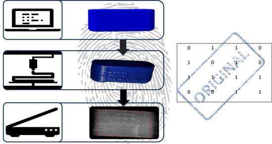
2.2.1. Hot Melt Extrusion
2.2.2. Creation of Geometries, G-Codes and Bits
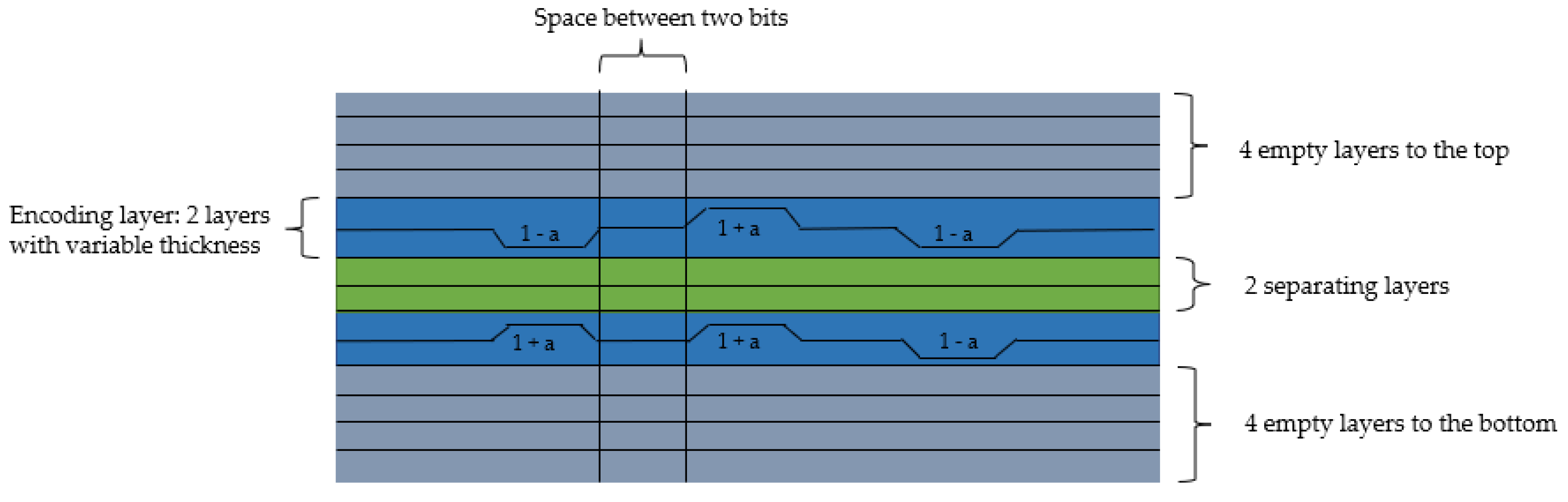
2.2.3. Watermark Embedding
2.2.4. 3D Printing Process
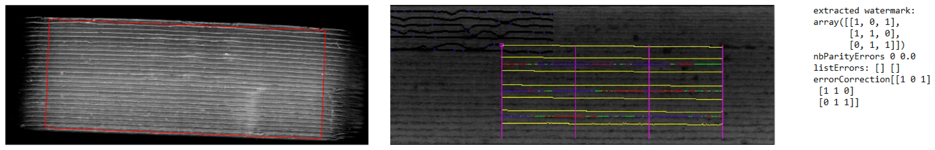
2.2.5. Scan and Detection
2.2.6. Melt Viscosity Measurements
3. Results and Discussion
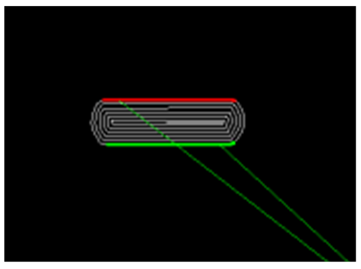
3.1. Minimum and Maximum Size of Oblong Shaped Tablets
3.2. Variation in Layer Height
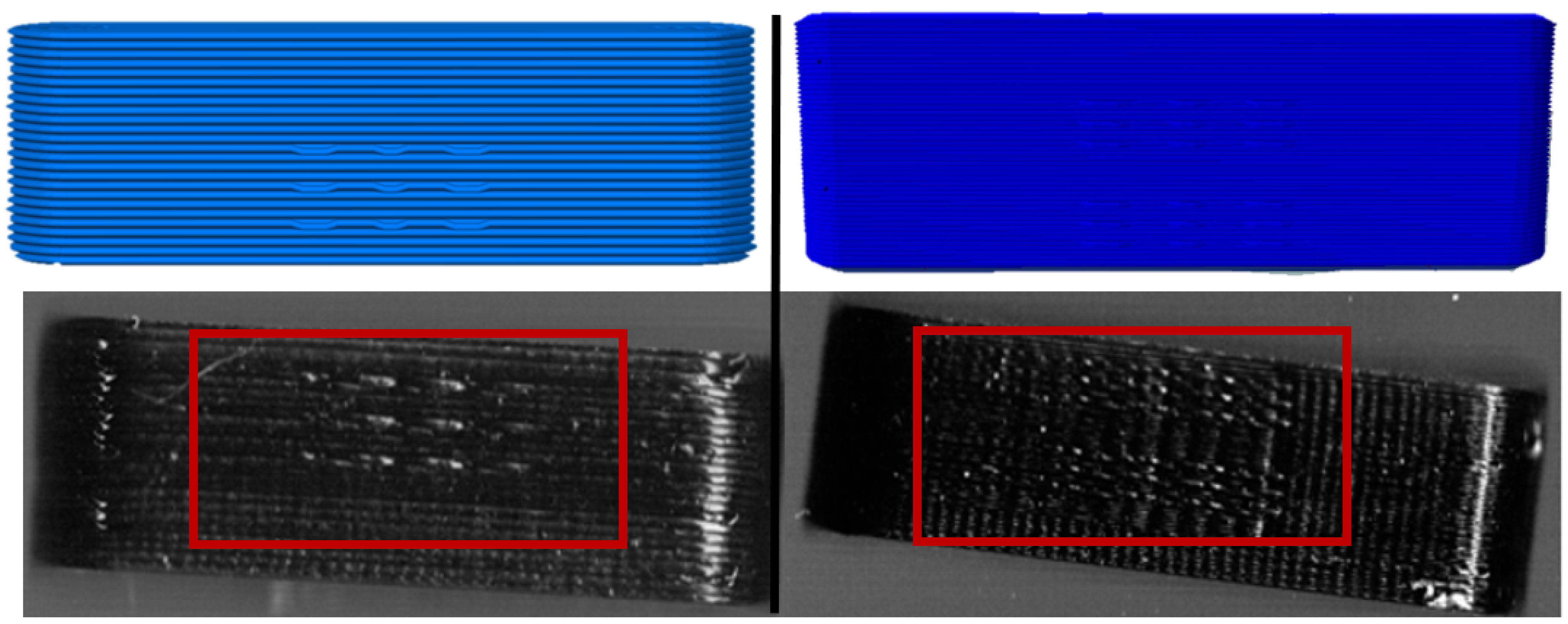
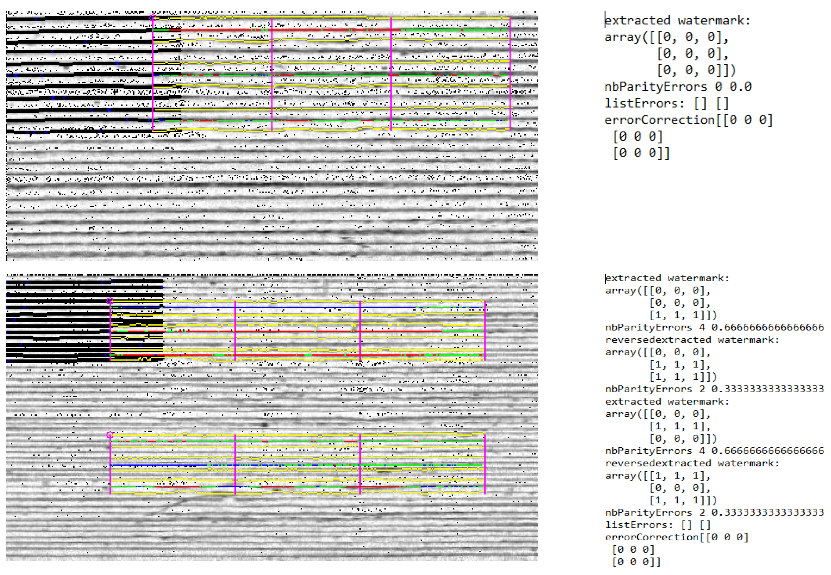
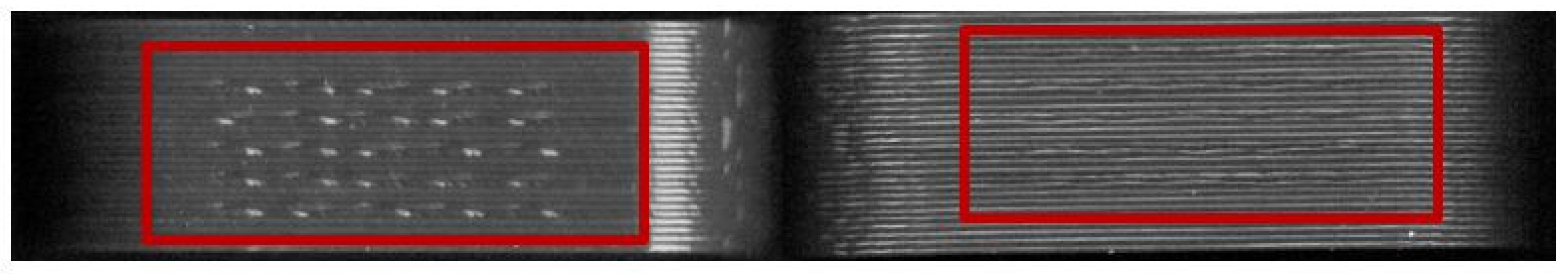
3.3. Optimization of the Scanning Process
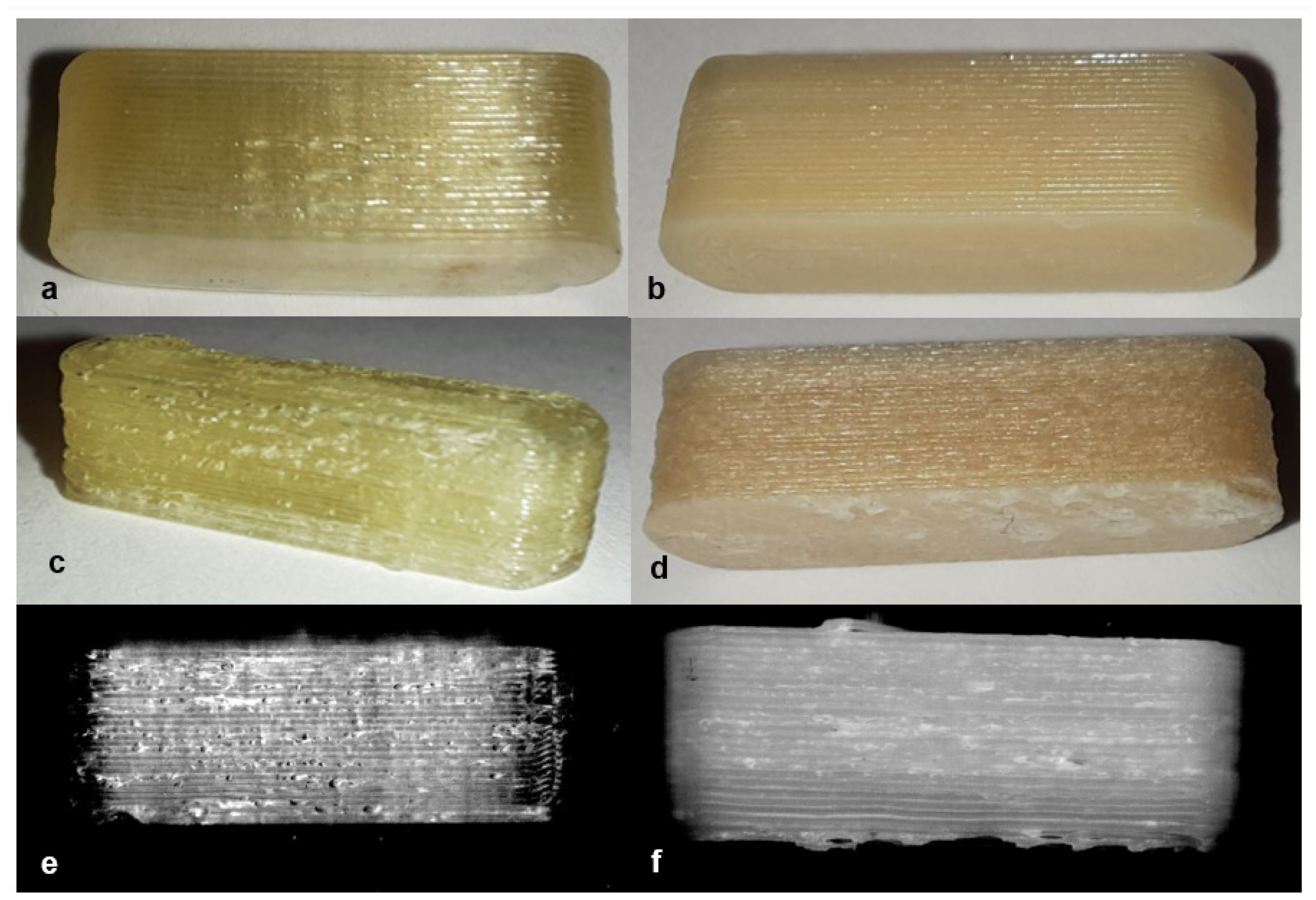
3.4. Variations of the Material
4. Conclusions
Author Contributions
Funding
Institutional Review Board Statement
Informed Consent Statement
Acknowledgments
Conflicts of Interest
References
- Substandard and Falsified Medical Products. Available online: https://www.who.int/health-topics/substandard-and-falsified-medical-products#tab=tab_1 (accessed on 30 December 2021).
- McManus, D.; Naughton, B.D. A Systematic Review of Substandard, Falsified, Unlicensed and Unregistered Medicine Sampling Studies: A Focus on Context, Prevalence, and Quality. BMJ Glob. Health 2020, 5, e002393. [Google Scholar] [CrossRef] [PubMed]
- Fernandez, F.M.; Hostetler, D.; Powell, K.; Kaur, H.; Green, M.D.; Mildenhall, D.C.; Newton, P.N. Poor Quality Drugs: Grand Challenges in High Throughput Detection, Countrywide Sampling, and Forensics in Developing Countries. Analyst 2011, 136, 3073–3082. [Google Scholar] [CrossRef] [PubMed] [Green Version]
- Feldschreiber, P. Public Health Issues with Counterfeit Medicines. Clin. Med. J. R. Coll. Physicians Lond. 2009, 9, 63–64. [Google Scholar] [CrossRef] [PubMed] [Green Version]
- Clark, F. Rise in Online Pharmacies Sees Counterfeit Drugs Go Global. Lancet 2015, 386, 1327–1328. [Google Scholar] [CrossRef]
- Fantasia, H.C.; Vooys, K.M. Public Health Implications of Counterfeit Medications. Nurs. Women’s Health 2018, 22, 264–268. [Google Scholar] [CrossRef] [PubMed]
- Hamilton, W.L.; Doyle, C.; Halliwell-Ewen, M.; Lambert, G. Public Health Interventions to Protect against Falsified Medicines: A Systematic Review of International, National and Local Policies. Health Policy Plan. 2016, 31, 1448–1466. [Google Scholar] [CrossRef] [PubMed] [Green Version]
- Sweileh, W.M. Substandard and Falsified Medical Products: Bibliometric Analysis and Mapping of Scientific Research. Glob. Health 2021, 17, 114. [Google Scholar] [CrossRef]
- Vorrath, J.; Voss, M. The Hidden Dangers of Falsified and Substandard Medicines. Developing Countries Are Most Affected by the Illegal Trade. Stift. Wiss. Politik Ger. Inst. Int. Secur. Aff. 2019, C25, 1–4. [Google Scholar] [CrossRef]
- Newton, P.N.; Dondorp, A.; Green, M.; Mayxay, M.; White, N.J. Counterfeit Artesunate Antimalarials in Southeast Asia. Lancet 2003, 362, 169. [Google Scholar] [CrossRef]
- Newton, P.N.; Caillet, C.; Guerin, P.J. A Link between Poor Quality Antimalarials and Malaria Drug Resistance? Expert Rev. Anti-Infect. Ther. 2016, 14, 531–533. [Google Scholar] [CrossRef] [Green Version]
- Bolla, A.S.; Patel, A.R.; Priefer, R. The Silent Development of Counterfeit Medications in Developing Countries—A Systematic Review of Detection Technologies. Int. J. Pharm. 2020, 587, 119702. [Google Scholar] [CrossRef] [PubMed]
- Rozendaal, J. Fake Antimalaria Drugs in Cambodia. Lancet 2001, 357, 890. [Google Scholar] [CrossRef]
- Chaccour, C.; Kaur, H.; del Pozo, J.L. Falsified Antimalarials: A Minireview. Expert Rev. Anti-Infect. Ther. 2015, 13, 505–509. [Google Scholar] [CrossRef] [PubMed]
- Arora, T.; Sharma, S. Global Scenario of Counterfeit Antimalarials: A Potential Threat. J. Vector Borne Dis. 2019, 56, 288–294. [Google Scholar] [CrossRef]
- Suthar, A.B.; Coggin, W.; Raizes, E. Antimicrobial Resistance and Substandard and Falsified Medicines: The Case of HIV/AIDS. J. Infect. Dis. 2019, 219, 672–673. [Google Scholar] [CrossRef] [PubMed]
- World Health Organization WHO Global Surveillance and Monitoring System for Substandard and Falsified Medical Products; World Health Organization: Geneva, Switzerland, 2017.
- Substandard and Falsified Medical Products. Available online: https://www.who.int/en/news-room/fact-sheets/detail/substandard-and-falsified-medical-products (accessed on 30 December 2021).
- Uddin, M. Blockchain Medledger: Hyperledger Fabric Enabled Drug Traceability System for Counterfeit Drugs in Pharmaceutical Industry. Int. J. Pharm. 2021, 597, 120235. [Google Scholar] [CrossRef]
- Han, S.; Bae, H.J.; Kim, J.; Shin, S.; Kwon, S.; Park, W. Drug Authentication Using High Capacity and Error-Correctable Encoded Microtaggants. In Proceedings of the 16th International Conference on Miniaturized Systems for Chemistry and Life Sciences, MicroTAS 2012, Okinawa, Japan, 28 October–1 November 2012; pp. 1429–1431. [Google Scholar]
- Falsified Medicines: Overview | European Medicines Agency. Available online: https://www.ema.europa.eu/en/human-regulatory/overview/public-health-threats/falsified-medicines-overview (accessed on 30 December 2021).
- Europol Information How COVID-19-Related Crime Infected Europe during 2020; European Union Agency for Law Enforcement Cooperation: Haag, The Netherlands, 2020.
- Europol Information Pandemic Profiteering—How Criminals Exploit the COVID-19 Crisis; European Union Agency for Law Enforcement Cooperation: Haag, The Netherlands, 2020.
- Layach, O.B. International and National Obligations to Protect from the Risks of Pharmaceutical Crime: The Crime of Counterfeit Pharmaceutical Products in the COVID-19 Crisis. Syst. Rev. Pharm. 2020, 11, 648–657. [Google Scholar] [CrossRef]
- Borse, N.N.; Cha, J.; Chase, C.G.; Gaur, R.; Koduri, C.K.; Kokai-Kun, J.F.; Kwan, D.C.; Lee, R.; Moore, J.C.; Raghavendran, V.; et al. Responding to the Surge of Substandard and Falsified Health Products Triggered by the Covid-19 Pandemic; USP: North Bethesda, MD, USA, 2021. [Google Scholar]
- Seibert, H.H.; Maddox, R.R.; Flynn, E.A.; Williams, C.K. Effect of Barcode Technology with Electronic Medication Administration Record on Medication Accuracy Rates. Am. J. Health-Syst. Pharm. 2014, 71, 209–218. [Google Scholar] [CrossRef]
- Klein, K.; Stolk, P. Challenges and Opportunities for the Traceability of (Biological) Medicinal Products. Drug Saf. 2018, 41, 911–918. [Google Scholar] [CrossRef] [Green Version]
- Alam, N.; Hasan Tanvir, M.R.; Shanto, S.A.; Israt, F.; Rahman, A.; Momotaj, S. Blockchain Based Counterfeit Medicine Authentication System. In Proceedings of the ISCAIE 2021—IEEE 11th Symposium on Computer Applications & Industrial Electronics, Penang, Malaysia, 3–4 April 2021; pp. 214–217. [Google Scholar] [CrossRef]
- Nawale, S.D.; Konapure, R.R. Blockchain IoT Based Drugs Traceability for Pharma Industry. In Proceedings of the 2021 IEEE International Conference on Engineering, Technology and Innovation (ICE/ITMC), Cardiff, UK, 21–23 June 2021; pp. 1–4. [Google Scholar] [CrossRef]
- Ludasi, K.; Jójárt-Laczkovich, O.; Sovány, T.; Hopp, B.; Smausz, T.; Andrásik, A.; Gera, T.; Kovács, Z.; Regdon, G. Anti-Counterfeiting Protection, Personalized Medicines − Development of 2D Identification Methods Using Laser Technology. Int. J. Pharm. 2021, 605, 120793. [Google Scholar] [CrossRef]
- European Commission Commission Delegated Regulation (EU) 2016/ 161. Official Journal of the European Union 2015. Available online: https://eur-lex.europa.eu/legal-content/EN/TXT/?uri=CELEX:32016R0161 (accessed on 30 December 2021).
- European Commission Directive 2011/62/EU Of The European Parliament And Of The Council of 8 June 2011 Amending Directive 2001/83/EC on the Community Code Relating to Medicinal Products for Human Use, as Regards the Prevention of the Entry into the Legal Supply Chain of Falsified Medicinal Products (Text with EEA Relevance). Official Journal of the European Union 2011. Available online: https://eur-lex.europa.eu/legal-content/EN/TXT/?uri=CELEX%3A32011L0062 (accessed on 30 December 2021).
- Sträter, B. Arzneimittelfälschungen: Maßnahmen Der Gesetzgeber in Der Europäischen Union Und in Deutschland. Bundesgesundheitsblatt—Gesundheitsforschung—Gesundheitsschutz 2017, 60, 1188–1195. [Google Scholar] [CrossRef] [PubMed]
- Szücs, C. 2D-Barcode Auf Der Verpackung—Ein System Zur Authentifizierung Verschreibungspflichtiger Arzneimitteln. Jusletter IT 2020, 599–606. [Google Scholar] [CrossRef]
- Roth, L.; Biggs, K.B.; Bempong, D.K. Substandard and Falsified Medicine Screening Technologies. AAPS Open 2019, 5, 1–12. [Google Scholar] [CrossRef] [Green Version]
- Hamburg, M.A.; Collins, F.S. The Path to Personalized Medicine. New Engl. J. Med. 2010, 363, 301–304. [Google Scholar] [CrossRef] [PubMed]
- Windolf, H.; Chamberlain, R.; Quodbach, J. Predicting Drug Release from 3D Printed Oral Medicines Based on the Surface Area to Volume Ratio of Tablet Geometry. Pharmaceutics 2021, 13, 1453. [Google Scholar] [CrossRef] [PubMed]
- Nørfeldt, L.; Bøtker, J.; Edinger, M.; Genina, N.; Rantanen, J. Cryptopharmaceuticals: Increasing the Safety of Medication by a Blockchain of Pharmaceutical Products. J. Pharm. Sci. 2019, 108, 2838–2841. [Google Scholar] [CrossRef]
- Trenfield, S.J.; Xian Tan, H.; Awad, A.; Buanz, A.; Gaisford, S.; Basit, A.W.; Goyanes, A. Track-and-Trace: Novel Anti-Counterfeit Measures for 3D Printed Personalized Drug Products Using Smart Material Inks. Int. J. Pharm. 2019, 567, 118443. [Google Scholar] [CrossRef]
- Hodson, R. Precision Medicine. Nature 2016, 537, S49. [Google Scholar] [CrossRef] [Green Version]
- Ashley, E.A. Towards Precision Medicine. Nat. Rev. Genet. 2016, 17, 507–522. [Google Scholar] [CrossRef]
- Edinger, M.; Bar-Shalom, D.; Sandler, N.; Rantanen, J.; Genina, N. QR Encoded Smart Oral Dosage Forms by Inkjet Printing. Int. J. Pharm. 2018, 536, 138–145. [Google Scholar] [CrossRef]
- Ishiyama, R.; Takahashi, T.; Makino, K.; Kudo, Y.; Kooper, M.; Abbink, D. Medicine Tablet Authentication Using Fingerprints of Ink-Jet Printed Characters. In Proceedings of the 2019 IEEE International Conference on Industrial Technology (ICIT), Melbourne, Australia, 13–15 February 2019; pp. 871–876. [Google Scholar] [CrossRef]
- Korte, C. 3D-Drug-Printing: Extrusion of Printable Drug-Loaded Filaments and Development of Novel Solid Dosage Forms. Ph.D. Thesis, Heinrich-Heine-Universität, Düsseldorf, Germany, 2018. [Google Scholar]
- Sadia, M.; Arafat, B.; Ahmed, W.; Forbes, R.T.; Alhnan, M.A. Channelled Tablets: An Innovative Approach to Accelerating Drug Release from 3D Printed Tablets. J. Control. Release 2018, 269, 355–363. [Google Scholar] [CrossRef] [PubMed]
- Goyanes, A.; Fina, F.; Martorana, A.; Sedough, D.; Gaisford, S.; Basit, A.W. Development of Modified Release 3D Printed Tablets (Printlets) with Pharmaceutical Excipients Using Additive Manufacturing. Int. J. Pharm. 2017, 527, 21–30. [Google Scholar] [CrossRef] [PubMed]
- Obeid, S.; Madžarević, M.; Ibrić, S. Tailoring Amlodipine Release from 3D Printed Tablets: Influence of Infill Patterns and Wall Thickness. Int. J. Pharm. 2021, 610, 121261. [Google Scholar] [CrossRef] [PubMed]
- Đuranović, M.; Madžarević, M.; Ivković, B.; Ibrić, S.; Cvijić, S. The Evaluation of the Effect of Different Superdisintegrants on the Drug Release from FDM 3D Printed Tablets through Different Applied Strategies: In Vitro-in Silico Assessment. Int. J. Pharm. 2021, 610, 121194. [Google Scholar] [CrossRef] [PubMed]
- Buyukgoz, G.G.; Kossor, C.G.; Davé, R.N. Enhanced Supersaturation via Fusion-Assisted Amorphization during Fdm 3d Printing of Crystalline Poorly Soluble Drug Loaded Filaments. Pharmaceutics 2021, 13, 1857. [Google Scholar] [CrossRef] [PubMed]
- Quodbach, J.; Bogdahn, M.; Breitkreutz, J.; Chamberlain, R.; Eggenreich, K.; Elia, A.G.; Gottschalk, N.; Gunkel-Grabole, G.; Hoffmann, L.; Kapote, D.; et al. Quality of FDM 3D Printed Medicines for Pediatrics: Considerations for Formulation Development, Filament Extrusion, Printing Process and Printer Design. Ther. Innov. Regul. Sci. 2021, 1, 1–19. [Google Scholar] [CrossRef]
- Cailleaux, S.; Sanchez-Ballester, N.M.; Gueche, Y.A.; Bataille, B.; Soulairol, I. Fused Deposition Modeling (FDM), the New Asset for the Production of Tailored Medicines. J. Control. Release 2021, 330, 821–841. [Google Scholar] [CrossRef]
- Chamberlain, R.; Windolf, H.; Geissler, S.; Quodbach, J.; Breitkreutz, J. Precise Dosing of Pramipexole for Low-Dosed Filament Production by Hot Melt Extrusion Applying Various Feeding Methods. Pharmaceutics 2022, 14, 216. [Google Scholar] [CrossRef]
- Delmotte, A.; Tanaka, K.; Kubo, H.; Funatomi, T.; Mukaigawa, Y. Blind Watermarking for 3-D Printed Objects by Locally Modifying Layer Thickness. IEEE Trans. Multimed. 2020, 22, 2780–2791. [Google Scholar] [CrossRef]
- Karagianni, A. Development of Printable Drug-Loaded Filaments (Rheological and Solid-State Characterization). Master Thesis, Heinrich-Heine-Universität, Düsseldorf, Germany, 2019. [Google Scholar]
- Ponsar, H.; Wiedey, R.; Quodbach, J. Hot-Melt Extrusion Process Fluctuations and Their Impact on Critical Quality Attributes of Filaments and 3D-Printed Dosage Forms. Pharmaceutics 2020, 12, 511. [Google Scholar] [CrossRef]
- Korte, C.; Quodbach, J. 3D-Printed Network Structures as Controlled-Release Drug Delivery Systems: Dose Adjustment, API Release Analysis and Prediction. AAPS PharmSciTech 2018, 19, 3333–3342. [Google Scholar] [CrossRef] [PubMed]
- Gelbe Liste Identa I Gelbe Liste. Available online: https://www.gelbe-liste.de/identa/results (accessed on 16 September 2021).
- Korte, C.; Quodbach, J. Formulation Development and Process Analysis of Drug-Loaded Filaments Manufactured via Hot-Melt Extrusion for 3D-Printing of Medicines. Pharm. Dev. Technol. 2018, 23, 1117–1127. [Google Scholar] [CrossRef] [PubMed]
- Genina, N.; Holländer, J.; Jukarainen, H.; Mäkilä, E.; Salonen, J.; Sandler, N. Ethylene Vinyl Acetate (EVA) as a New Drug Carrier for 3D Printed Medical Drug Delivery Devices. Eur. J. Pharm. Sci. 2016, 90, 53–63. [Google Scholar] [CrossRef] [PubMed]
- Henry, S.; de Wever, L.; Vanhoorne, V.; de Beer, T.; Vervaet, C. Influence of Print Settings on the Critical Quality Attributes of Extrusion-Based 3D-Printed Caplets: A Quality-by-Design Approach. Pharmaceutics 2021, 13, 2068. [Google Scholar] [CrossRef] [PubMed]
- Crișan, A.G.; Porfire, A.; Ambrus, R.; Katona, G.; Rus, L.M.; Porav, A.S.; Ilyés, K.; Tomuță, I. Polyvinyl Alcohol-Based 3d Printed Tablets: Novel Insight into the Influence of Polymer Particle Size on Filament Preparation and Drug Release Performance. Pharmaceuticals 2021, 14, 418. [Google Scholar] [CrossRef]
- Nober, C.; Manini, G.; Carlier, E.; Raquez, J.M.; Benali, S.; Dubois, P.; Amighi, K.; Goole, J. Feasibility Study into the Potential Use of Fused-Deposition Modeling to Manufacture 3D-Printed Enteric Capsules in Compounding Pharmacies. Int. J. Pharm. 2019, 569, 118581. [Google Scholar] [CrossRef]
- Gottschalk, N.; Bogdahn, M.; Harms, M.; Quodbach, J. Brittle Polymers in Fused Deposition Modeling: An Improved Feeding Approach to Enable the Printing of Highly Drug Loaded Filament. Int. J. Pharm. 2021, 597, 120216. [Google Scholar] [CrossRef]
- Bandari, S.; Nyavanandi, D.; Dumpa, N.; Repka, M.A. Coupling Hot Melt Extrusion and Fused Deposition Modeling: Critical Properties for Successful Performance. Adv. Drug Deliv. Rev. 2021, 172, 52–63. [Google Scholar] [CrossRef]
- Zhang, J.; Xu, P.; Vo, A.Q.; Bandari, S.; Yang, F.; Durig, T.; Repka, M.A. Development and Evaluation of Pharmaceutical 3D Printability for Hot Melt Extruded Cellulose-Based Filaments. J. Drug Deliv. Sci. Technol. 2019, 52, 292–302. [Google Scholar] [CrossRef]


| Filament | Materials | Concentration/% | Manufacturer/Source |
|---|---|---|---|
| PLA | Polylactic acid (PLA) | 100 | Bavaria filaments, Freilassing, Germany |
| PVA | Polyvinyl alcohol (PVA) | 100 | Parteck MXP®, Merck, Darmstadt, Germany |
| PVA + PZQ [37] | Polyvinyl alcohol (PVA) | 95 | Parteck MXP®, Merck, Darmstadt, Germany |
| Praziquantel (PZQ) | 5 | Bayer AG, Leverkusen, Germany | |
| PVA + PDM [37] | Polyvinyl alcohol (PVA) | 84 | Parteck MXP®, Merck, Darmstadt, Germany |
| Mannitol | 10 | Parteck M®, Merck, Darmstadt, Germany | |
| Pramipexole 2 HCl*H2O (PDM) | 5 | Chr. Olesen, Gentofte, Denmark | |
| Fumed silica | 1 | Aerosil® 200 VV Pharma, Evonik, Essen, Germany | |
| PVA + Triam [54] | Triamcinolone acetonide (Triam) | 5 | Farmabios, Gropello Cairoli, Italy |
| Polyethylene glycol 300 | 10 | Polyglycol 300, Clariant, Pratteln, Switzerland | |
| Polyvinyl alcohol (PVA) | 85 | Parteck MXP®, Merck, Darmstadt, Germany | |
| PVA + colorant | Polyvinyl alcohol (PVA) | 84 | Parteck MXP®, Merck, Darmstadt, Germany |
| Mannitol | 10 | Parteck M®, Merck, Darmstadt, Germany | |
| Methylene blue | 5 | Spectrum Lab Products, Gardena, CA, US | |
| Fumed silica | 1 | Aerosil® 200 VV Pharma, Evonik, Essen, Germany | |
| EPO + API | Basic butylated-methacrylate- copolymer (EPO) | 80 | Eudragit E PO®, Evonik, Essen, Germany |
| Pramipexole 2 HCl*H2O (PDM) | 20 | Chr. Olesen, Gentofte, Denmark | |
| EC | Ethyl cellulose (EC) | 100 | Aqualon® N10, Ashland, KY, US |
| EC + HPMC [55] | Ethyl cellulose (EC) | 72.93 | Aqualon® N10, Ashland, KY, US |
| Hypromellose (HPMC) | 16.67 | Metolose 60SH 50, Shin Etsu Chemical, Tokyo, Japan | |
| Triethyl citrate | 10 | Citrofol AI Extra, Jungbunzlauer, Basel, Switzerland | |
| Fumed silica | 0.4 | Aerosil® 200 VV Pharma, Evonik, Essen, Germany | |
| EVA + PVA | Ethylene-vinyl acetate copolymer 82:18 (EVA) | 25 | Escorene® FL01418, TER Chemicals, Hamburg, Germany |
| Polyvinyl alcohol (PVA) | 65 | Parteck MXP®, Merck, Darmstadt, Germany | |
| Mannitol | 10 | Parteck M®, Merck, Darmstadt, Germany | |
| EVA + PVP-VA + API | Ethylene-vinyl acetate copolymer 82:18 (EVA) | 35 | Escorene® FL01418, TER Chemicals, Hamburg, Germany |
| Vinylpyrrolidone-vinyl acetate copolymer 60:40 (PVP-VA) | 15 | Kollidon VA 64®, BASF, Ludwigshafen a. R., Germany | |
| Levodopa | 40 | Zhejiang Wild Wind Pharmaceutical, Dongyang, China | |
| Benserazide | 10 | BioPharma Synergies, Barcelona, Spain | |
| ERL + API [56] | Anhydrous Theophylline | 30 | BASF, Ludwigshafen a. R., Germany |
| Ammonio-methacrylate-copolymer type A (ERL) | 62.6 | Eudragit® RL PO, Evonik, Essen, Germany | |
| Stearic acid | 7 | Baerlocher, Lingen, Germany | |
| Fumed silica | 0.4 | Aerosil® 200 VV Pharma, Evonik, Essen, Germany |
| Filament | Bed Temperature/°C | Nozzle Temperature/°C |
|---|---|---|
| PLA | 60 | 215 |
| PVA | 90 | 190 |
| PVA + PZQ | 90 | 188 |
| PVA + PDM/colorant | 60 | 188 |
| PVA + Triam | 60 | 190 |
| EPO + API | 45 | 176 |
| ERL + API | 55 | 180 |
| EC | 60 | 180 |
| EC + HPMC | 63 | 180 |
| EVA + PVA | 50 | 220 |
| EVA + PVP-VA + API | 50 | 220 |
| Filament | Brightness | Contrast |
|---|---|---|
| PLA | −19 | 31 |
| PVA | −100 | 30 |
| PVA + PZQ | −100 | 55 |
| PVA + PDM | −19 | 70 |
| PVA + colorant | −50 | 25 |
| PVA + Triam | −100 | 50 |
| EPO + API | −100 | 60 |
| ERL + API | −100 | 40 |
| EC | −45 | 40 |
| EC + HPMC | −80 | 55 |
| EVA + PVA | −70 | 40 |
| EVA + PVP-VA + API | −70 | 40 |
| 0 | 1 | 1 |
| 1 | 1 | 0 |
| 1 | 0 | 1 |
| 0 | 0 | 1 | 0 | 0 | 1 | 1 | 1 | 0 |
| 0 | 0 | 0 | 1 | 1 | 1 | 0 | 0 | 1 |
| 1 | 1 | 1 | 1 | 1 | 1 | 1 | 0 | 1 |
| 1 | 0 | 0 | 1 | 0 | 0 | 1 | 0 | 1 |
| 0 | 1 | 0 | 1 | 0 | 1 | 1 | 1 | 1 |
| 1 | 1 | 0 | 0 | 0 |
| 0 | 1 | 1 | 0 | 0 |
| 1 | 1 | 0 | 1 | 1 |
| 1 | 1 | 0 | 0 | 0 |
| 1 | 0 | 1 | 1 | 1 |
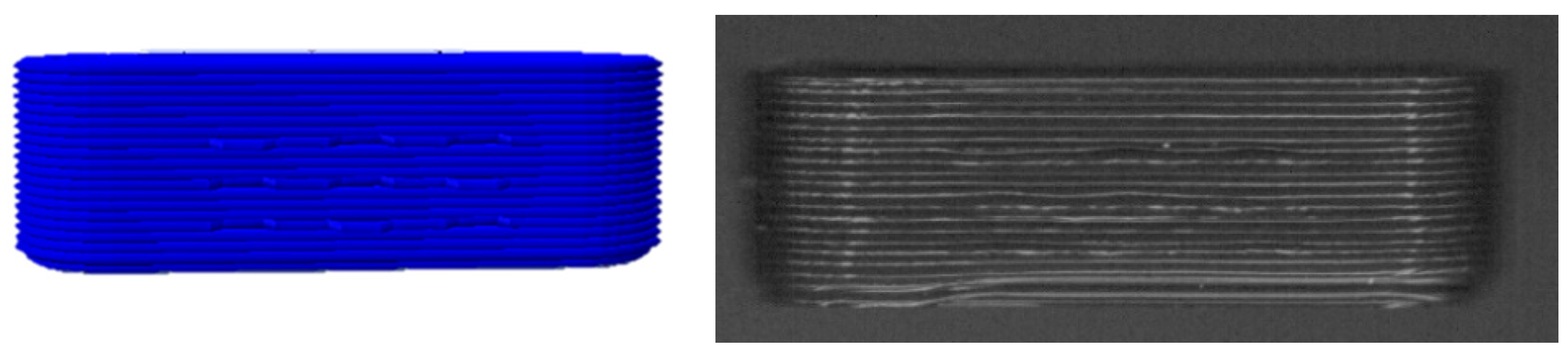
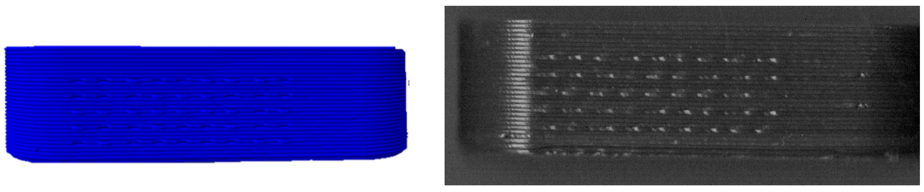
| Filament | Image | Scan (Parallel Orientation) | Detection | |
|---|---|---|---|---|
| PLA |  |  | Yes 3/3 | (a) |
| PVA |  |  | No 0/3 | (b) |
| PVA + PZQ |  |  | No 1/3 | (c) |
| PVA + PDM |  |  | No 0/3 | (d) |
| PVA + colorant |  |  | Yes 3/3 | (e) |
| PVA + Triam |  |  | Yes 3/3 | (f) |
| EPO + API |  |  | Yes 3/3 | (g) |
| EC |  |  | Yes 3/3 | (h) |
| EC + HPMC |  |  | Yes 3/3 | (i) |
| EVA + PVA |  |  | No 0/3 | (j) |
| EVA + PVP -VA + API |  |  | No 0/3 | (k) |
| ERL + API |  |  | No 0/3 | (l) |
| Filament | Nozzle Temperature/°C | Melt Viscosity/kPa*s |
|---|---|---|
| PVA | 190 | 7.251 |
| PVA + PZQ/PDM/colorant | 188 | 6.407 |
| PVA + Triam | 190 | 4.321 |
| EPO + API | 176 | 0.169 |
| EC | 180 | 24.200 |
| EC + HPMC | 180 | 15.920 |
| EVA + PVA | 220 | 0.251 |
| EVA + PVP-VA + API | 220 | 0.135 |
| Filament | Transparent/ Reflective | Surface Roughness | Visible to the Eye | Detectable | Likely Reason |
|---|---|---|---|---|---|
| PLA | no | no | yes | yes | Good solidification behavior, no roughness, no reflection. |
| PVA | yes | no | yes | no | Transparent, reflection of the scan-light. High melt viscosity. |
| PVA + API | Dissolved API: yes Susp. API: no | no | yes | Dissolved API: no Susp. API: yes | Transparent, dissolved API does not decrease the reflection of the scan-light, suspended API or excipient forms slight milky filaments. High melt viscosity. |
| PVA + colorant | no | no | yes | yes | The colorant decreases the transparency of PVA. High melt viscosity. |
| EPO + API | no | no | yes | yes | Good solidification behaviour, low melt viscosity, no roughness, no reflection. |
| ERL + API | no | yes | no | no | Too rough, no bits recognizable. |
| EC | no | no | yes | yes | Good solidification behaviour, high melt viscosity, no roughness, no reflection. |
| EC + HPMC | no | no | yes | yes | Good solidification behaviour, high melt viscosity, no roughness, no reflection. |
| EVA + PVA | no | no | no | no | Solidification of the printed object occurs too slowly + low melt viscosity, the bits and layers deform. |
| EVA + PVP-VA + API | no | yes | no | no | Solidification of the printed object occurs too slowly + low melt viscosity, the bits and layers deform. |
Publisher’s Note: MDPI stays neutral with regard to jurisdictional claims in published maps and institutional affiliations. |
© 2022 by the authors. Licensee MDPI, Basel, Switzerland. This article is an open access article distributed under the terms and conditions of the Creative Commons Attribution (CC BY) license (https://creativecommons.org/licenses/by/4.0/).
Share and Cite
Windolf, H.; Chamberlain, R.; Delmotte, A.; Quodbach, J. Blind-Watermarking—Proof-of-Concept of a Novel Approach to Ensure Batch Traceability for 3D Printed Tablets. Pharmaceutics 2022, 14, 432. https://doi.org/10.3390/pharmaceutics14020432
Windolf H, Chamberlain R, Delmotte A, Quodbach J. Blind-Watermarking—Proof-of-Concept of a Novel Approach to Ensure Batch Traceability for 3D Printed Tablets. Pharmaceutics. 2022; 14(2):432. https://doi.org/10.3390/pharmaceutics14020432
Chicago/Turabian StyleWindolf, Hellen, Rebecca Chamberlain, Arnaud Delmotte, and Julian Quodbach. 2022. "Blind-Watermarking—Proof-of-Concept of a Novel Approach to Ensure Batch Traceability for 3D Printed Tablets" Pharmaceutics 14, no. 2: 432. https://doi.org/10.3390/pharmaceutics14020432