
Electrospun Amphiphilic Nanofibers as Templates for In Situ Preparation of Chloramphenicol-Loaded Liposomes

 ,
,  , and
, and
Abstract
: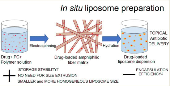
1. Introduction
2. Materials and Methods
2.1. Materials
2.2. Methods
2.2.1. The Preparation of Electrospun Amphiphilic Nanofibers
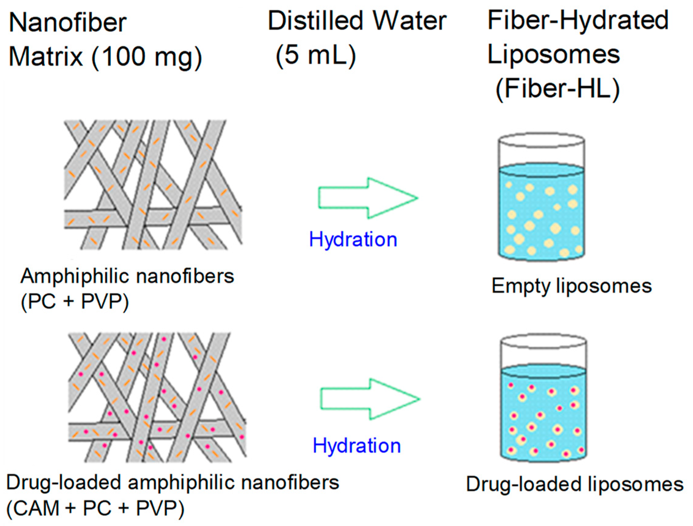
2.2.2. Preparation of Liposomes
2.2.3. Electrospun Nanofibers’ Characterization
Surface Topography and Morphology
Solid State Characterization and Sample Homogeneity
2.2.4. Liposome Characterization
Surface Topography and Morphology
Particle Size Analysis—Photon Correlation Spectroscopy (PCS)
Drug Encapsulation Efficiency—High-Performance Liquid Chromatography (HPLC)
In-Vitro Drug Release
Stability Testing during Storage
2.2.5. Data Analysis
Diameter Measurement of the Electrospun Nanofibers
Drug-Release Study
Statistics
3. Results and Discussion
3.1. Characterizing Electrospun Amphiphilic Fibers as Templates for Liposome Formation
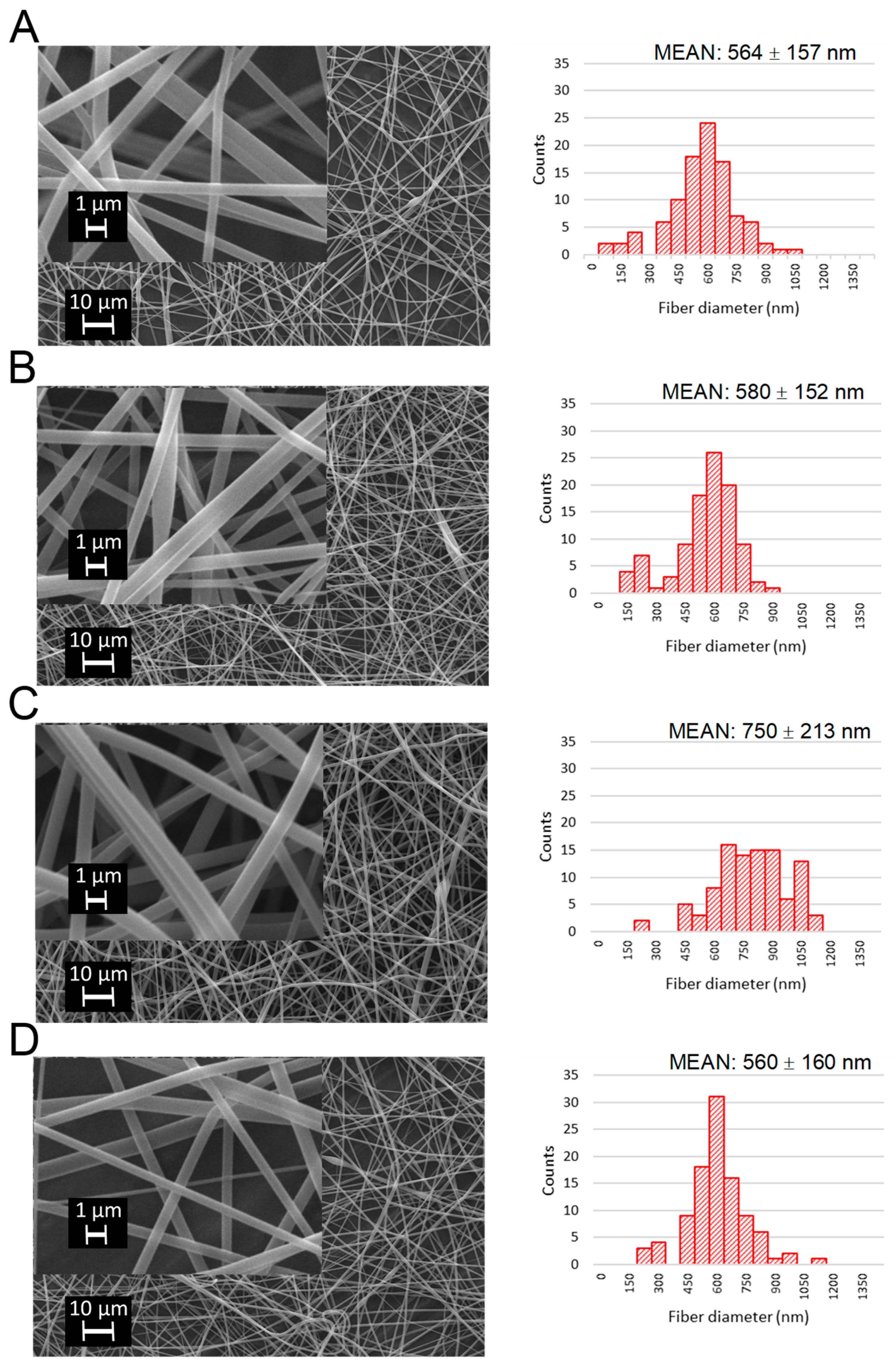
Morphology of Fibers
3.2. Solid State Characterization of Fibers
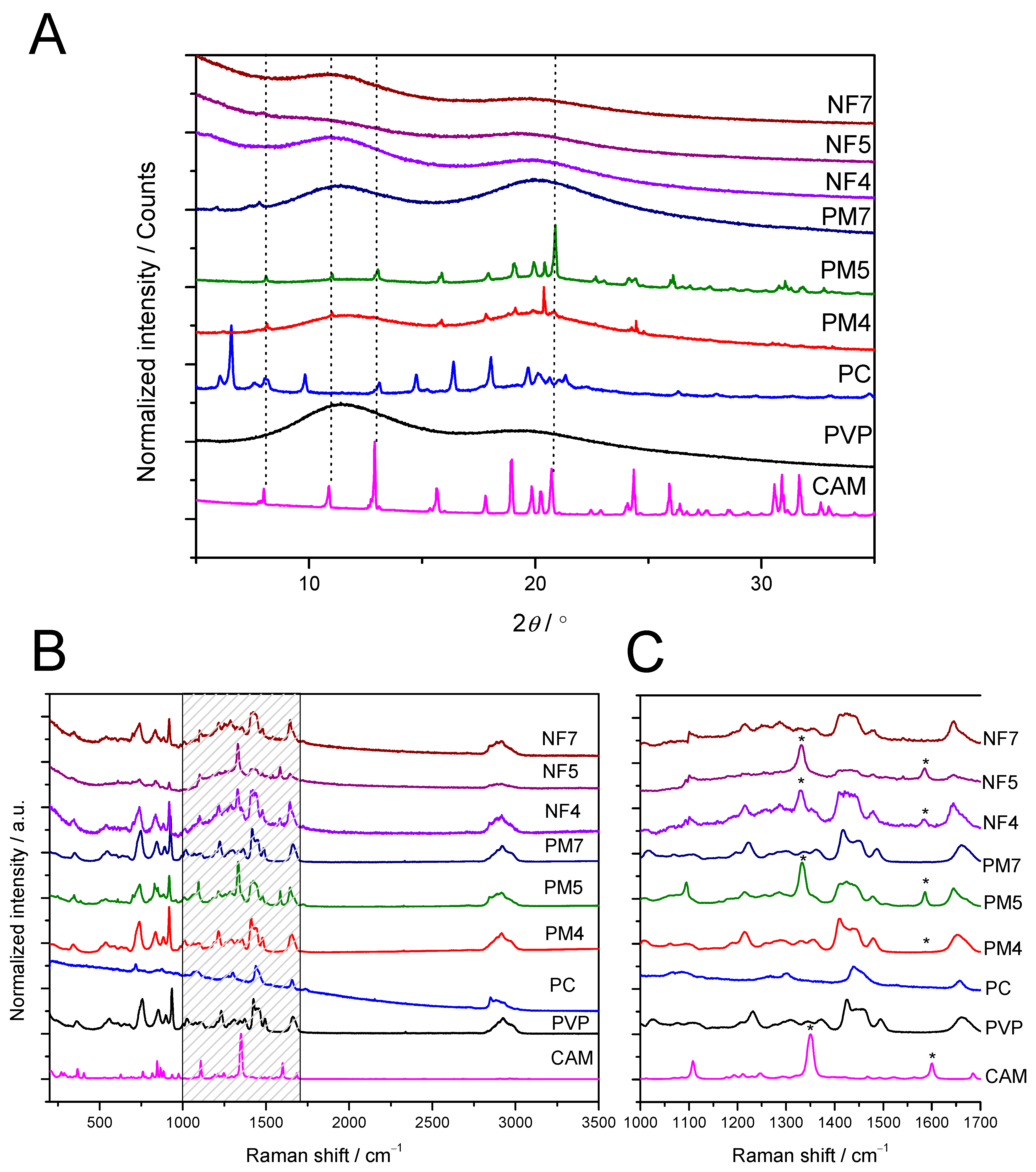
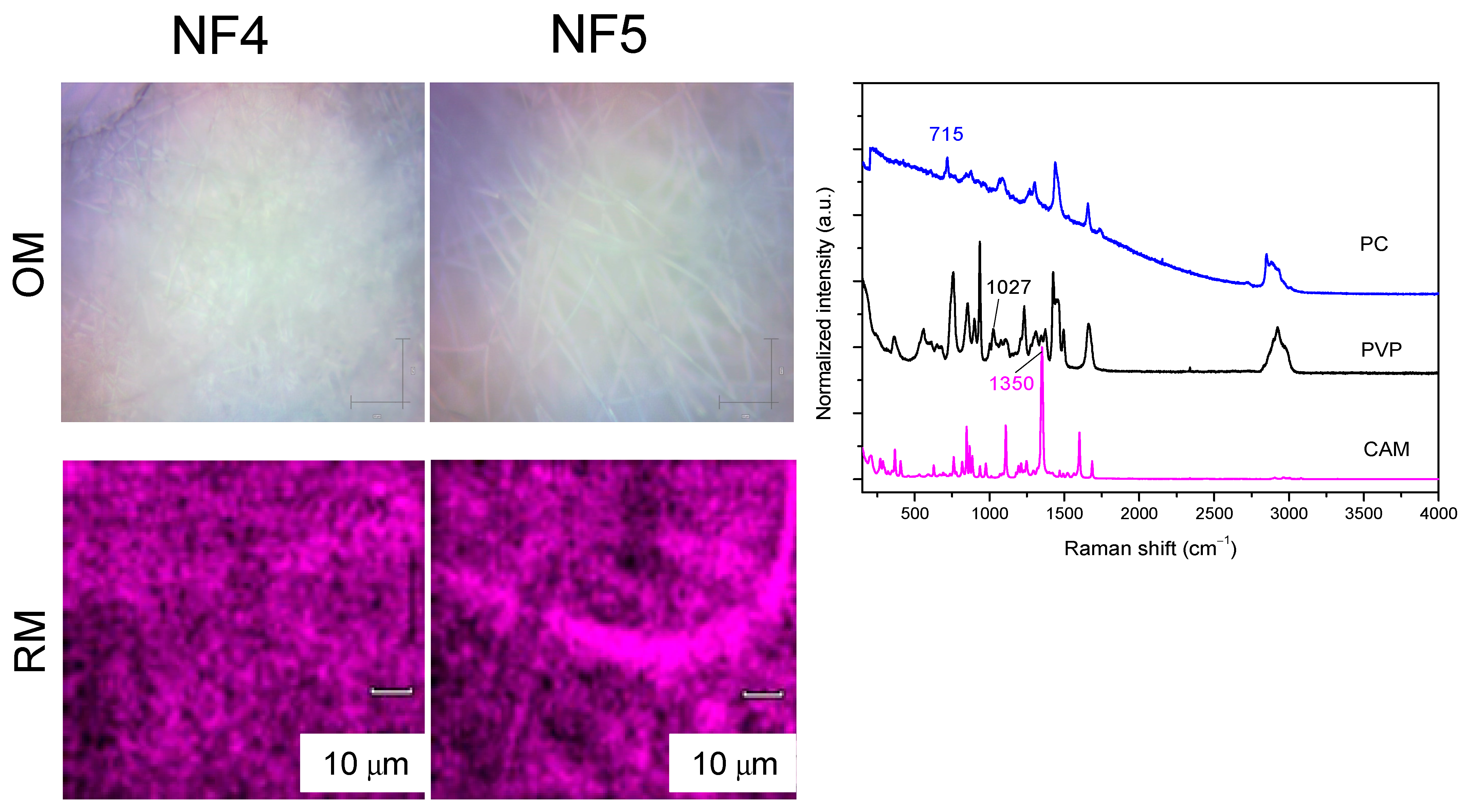
3.2.1. XRD and Raman Mapping
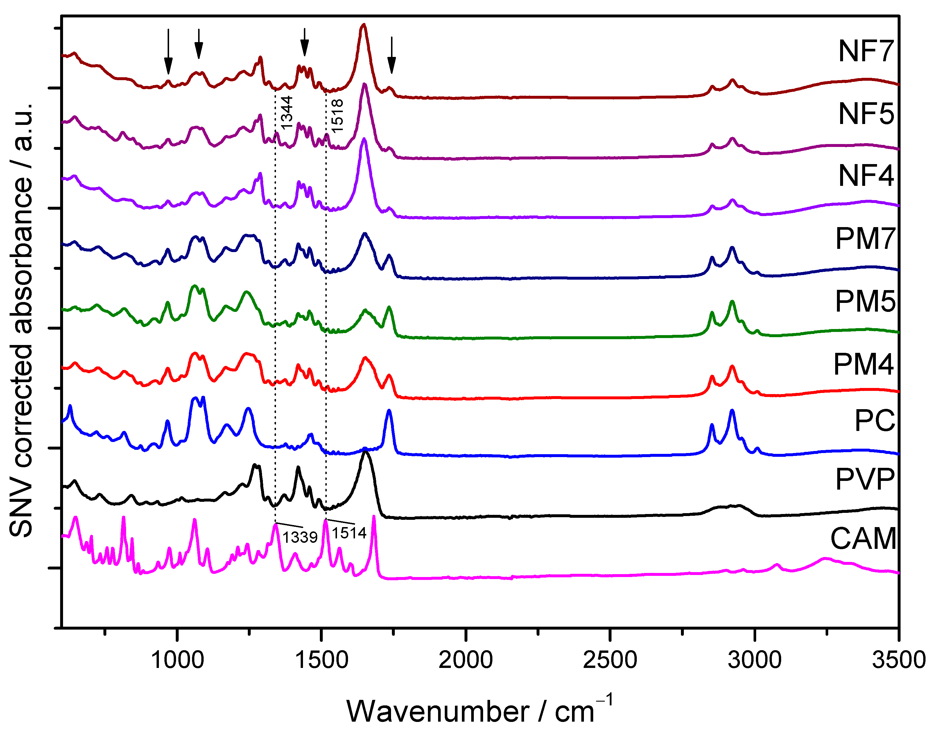
3.2.2. ATR-FTIR Spectroscopy
3.3. Characterization of Liposomes
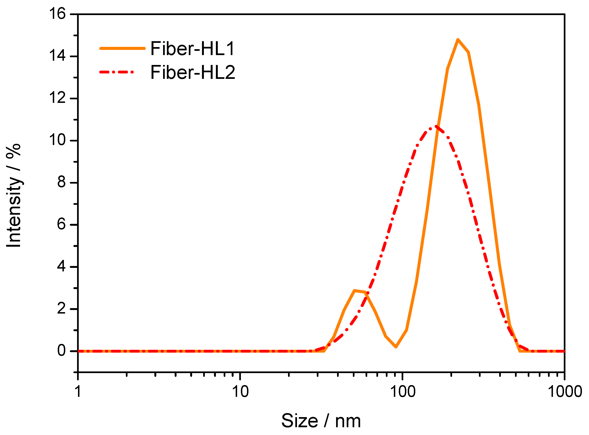
3.3.1. Morphology and Size of Fiber-Hydrated (Fiber-HL) and Film-Hydrated Liposomes (Film-HL)
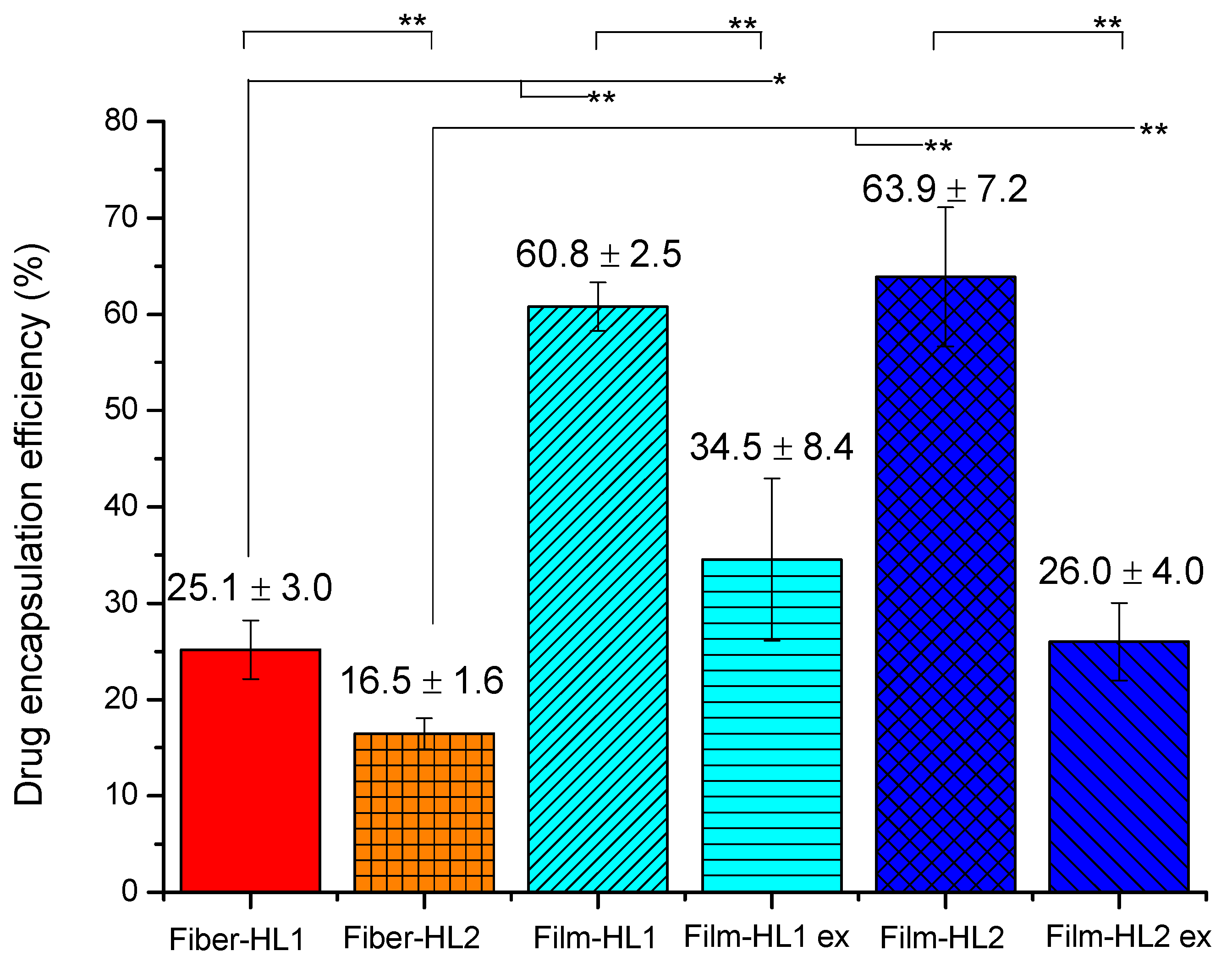
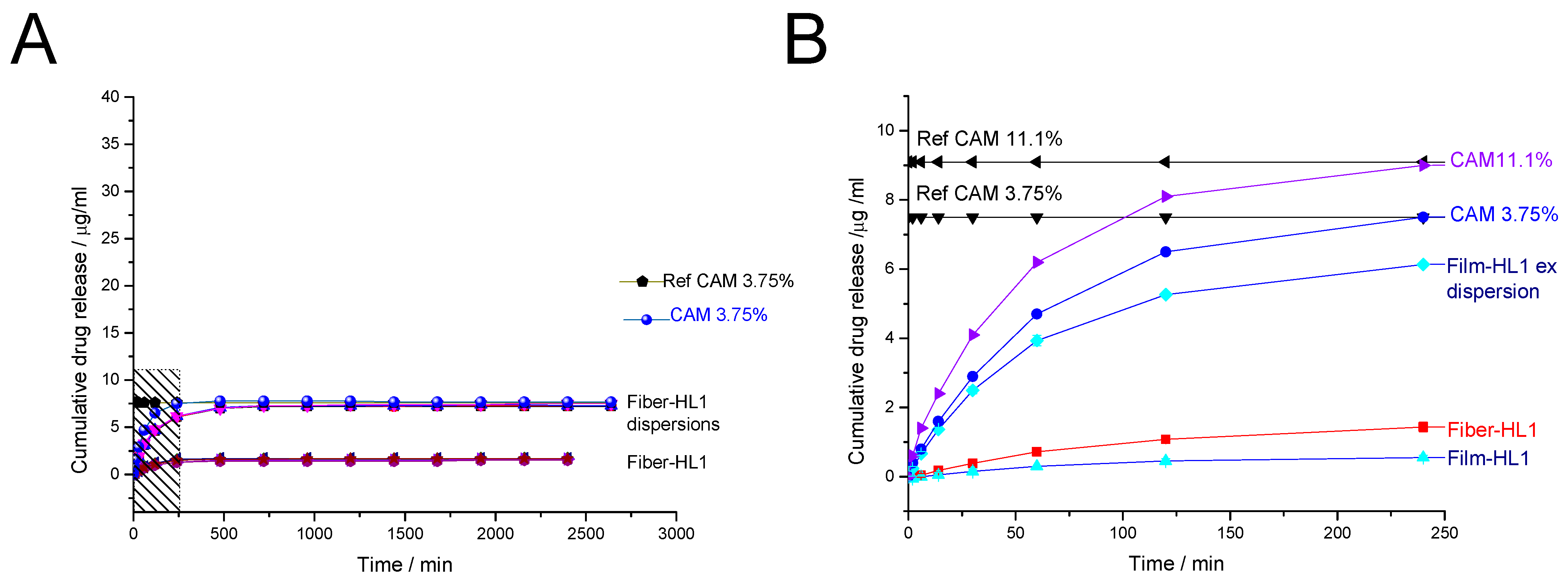
3.3.2. Drug Release from Fiber-Hydrated and Film-Hydrated Liposomes
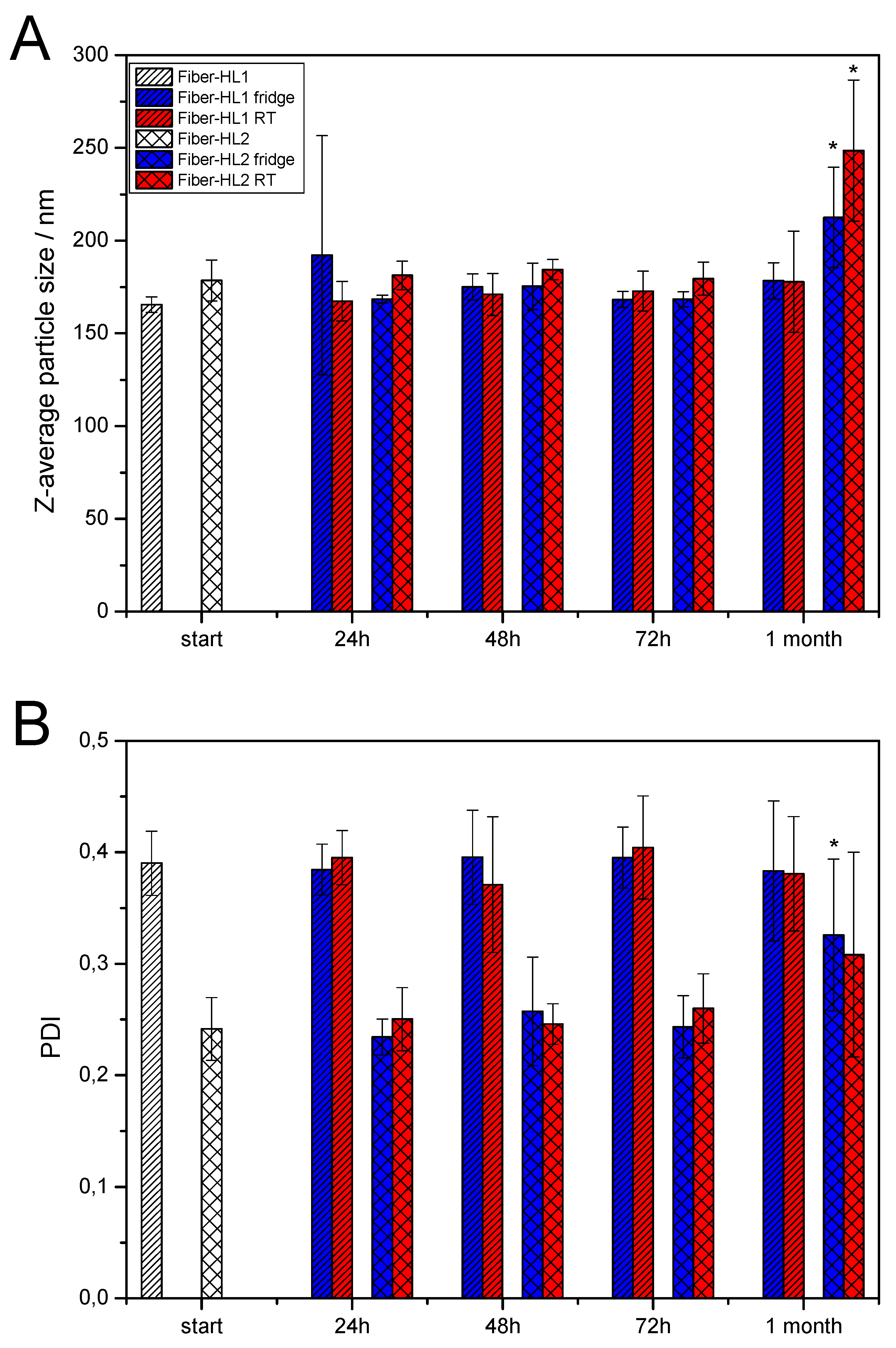
3.3.3. Storage Stability of Self-Formed Fiber-Hydrated Liposomes
4. General Discussion and Conclusions
Supplementary Materials
Author Contributions
Funding
Institutional Review Board Statement
Informed Consent Statement
Acknowledgments
Conflicts of Interest
References
- Patil, Y.P.; Jadhav, S. Novel methods for liposome preparation. Chem. Phys. Lipids 2014, 177, 8–18. [Google Scholar] [CrossRef]
- Paul, P.; Nandi, G. In Situ Polymeric Gels for Topical Drug Delivery; Springer: Cham, Switzerland, 2020; pp. 83–114. [Google Scholar] [CrossRef]
- Singh, K.; Verma, S.; Prasad, S.; Bala, I. Novel Formulation Development and Evaluation of Nanoparticles Based in Situ Gelling System for The Ophthalmic Delivery of Ciprofloxacin Hydrochloride. Int. J. Drug Deliv. Technol. 2015, 5. [Google Scholar] [CrossRef] [Green Version]
- Destruel, P.-L.; Zeng, N.; Maury, M.; Mignet, N.; Boudy, V. In vitro and in vivo evaluation of in situ gelling systems for sustained topical ophthalmic delivery: State of the art and beyond. Drug Discov. Today 2017, 22, 638–651. [Google Scholar] [CrossRef]
- Bangham, A.; Standish, M.; Watkins, J. Diffusion of univalent ions across the lamellae of swollen phospholipids. J. Mol. Biol. 1965, 13, 238–252. [Google Scholar] [CrossRef]
- Gouda, A.; Sakr, O.S.; Nasr, M.; Sammour, O. Ethanol injection technique for liposomes formulation: An insight into development, influencing factors, challenges and applications. J. Drug Deliv. Sci. Technol. 2020, 61, 102174. [Google Scholar] [CrossRef]
- Jaafar-Maalej, C.; Diab, R.; Andrieu, V.; Elaissari, A.; Fessi, H. Ethanol injection method for hydrophilic and lipophilic drug-loaded liposome preparation. J. Liposome Res. 2009, 20, 228–243. [Google Scholar] [CrossRef] [PubMed]
- Brunner, J.; Skrabal, P.; Hausser, H. Single bilayer vesicles prepared without sonication physico-chemical properties. Biochim. Biophys. Acta (BBA) Biomembr. 1976, 455, 322–331. [Google Scholar] [CrossRef]
- Pidgeon, C.; McNeely, S.; Schmidt, T.; Johnson, J.E. Multilayered vesicles prepared by reverse-phase evaporation: Liposome structure and optimum solute entrapment. Biochemistry 1987, 26, 17–29. [Google Scholar] [CrossRef] [PubMed]
- Yu, B.; Lee, R.J.; Lee, L.J. Microfluidic Methods for Production of Liposomes. Methods Enzymol. 2009, 465, 129–141. [Google Scholar] [CrossRef] [PubMed] [Green Version]
- Berger, N.; Sachse, A.; Bender, J.; Schubert, R.; Brandl, M. Filter extrusion of liposomes using different devices: Comparison of liposome size, encapsulation efficiency, and process characteristics. Int. J. Pharm. 2001, 223, 55–68. [Google Scholar] [CrossRef]
- Mozafari, M.R. Liposomes: An overview of manufacturing techniques. Cell. Mol. Biol. Lett. 2005, 10, 711–719. Available online: http://www.ncbi.nlm.nih.gov/pubmed/16341279 (accessed on 14 November 2015).
- Maherani, B.; Arab-Tehrany, E.; Mozafari, M.R.; Gaiani, C.; Linder, M. Liposomes: A Review of Manufacturing Techniques and Targeting Strategies. Curr. Nanosci. 2011, 7, 436–452. [Google Scholar] [CrossRef]
- Maja, L.; Željko, K.; Mateja, P. Sustainable technologies for liposome preparation. J. Supercrit. Fluids 2020, 165, 104984. [Google Scholar] [CrossRef]
- Mozafari, M.R.; Reed, C.J.; Rostron, C.; Kocum, C.; Piskin, E. Construction of stable anionic liposome-plasmid particles using the heating method: A preliminary investigation. Cell. Mol. Biol. Lett. 2002, 7, 923–928. [Google Scholar] [PubMed]
- Damiati, S.; Kompella, U.B.; Damiati, S.A.; Kodzius, R. Microfluidic Devices for Drug Delivery Systems and Drug Screening. Genes 2018, 9, 103. [Google Scholar] [CrossRef] [PubMed] [Green Version]
- Rezvantalab, S.; Moraveji, M.K. Microfluidic assisted synthesis of PLGA drug delivery systems. RSC Adv. 2019, 9, 2055–2072. [Google Scholar] [CrossRef] [Green Version]
- Yu, D.-G.; Branford-White, C.; Williams, G.R.; Bligh, S.W.A.; White, K.; Zhu, L.-M.; Chatterton, N.P. Self-assembled liposomes from amphiphilic electrospun nanofibers. Soft Matter 2011, 7, 8239–8247. [Google Scholar] [CrossRef]
- Huang, Z.-M.; Zhang, Y.; Kotaki, M.; Ramakrishna, S. A review on polymer nanofibers by electrospinning and their applications in nanocomposites. Compos. Sci. Technol. 2003, 63, 2223–2253. [Google Scholar] [CrossRef]
- Vasireddi, R.; Kruse, J.; Vakili, M.; Kulkarni, S.; Keller, T.F.; Monteiro, D.C.F.; Trebbin, M. Solution blow spinning of polymer/nanocomposite micro-/nanofibers with tunable diameters and morphologies using a gas dynamic virtual nozzle. Sci. Rep. 2019, 9, 12497. [Google Scholar] [CrossRef] [Green Version]
- Jiang, S.; Chen, Y.; Duan, G.; Mei, C.; Greiner, A.; Agarwal, S. Electrospun nanofiber reinforced composites: A review. Polym. Chem. 2018, 9, 2685–2720. [Google Scholar] [CrossRef]
- Torres-Martinez, E.J.; Bravo, J.M.C.; Medina, A.S.; Pérez-González, G.L.; Gómez, L.J.V. A Summary of Electrospun Nanofibers as Drug Delivery System: Drugs Loaded and Biopolymers Used as Matrices. Curr. Drug Deliv. 2018, 15, 1360–1374. [Google Scholar] [CrossRef]
- Rinoldi, C.; Zargarian, S.S.; Nakielski, P.; Li, X.; Liguori, A.; Petronella, F.; Presutti, D.; Wang, Q.; Costantini, M.; De Sio, L.; et al. Nanotechnology-Assisted RNA Delivery: From Nucleic Acid Therapeutics to COVID-19 Vaccines. Small Methods 2021, 5, 2100402. [Google Scholar] [CrossRef] [PubMed]
- Yang, X.; Wang, J.; Guo, H.; Liu, L.; Xu, W.; Duan, G. Structural design toward functional materials by electrospinning: A review. e-Polymers 2020, 20, 682–712. [Google Scholar] [CrossRef]
- Nguyen, K.V.; Laidmäe, I.; Kogermann, K.; Lust, A.; Meos, A.; Ho, D.V.; Raal, A.; Heinämäki, J.; Nguyen, H.T. Preformulation Study of Electrospun Haemanthamine-Loaded Amphiphilic Nanofibers Intended for a Solid Template for Self-Assembled Liposomes. Pharmaceutics 2019, 11, 499. [Google Scholar] [CrossRef] [Green Version]
- Song, H.-H.; Gong, X.; Williams, G.R.; Quan, J.; Nie, H.-L.; Zhu, L.-M.; Nan, E.-L.; Shao, M. Self-assembled magnetic liposomes from electrospun fibers. Mater. Res. Bull. 2014, 53, 280–289. [Google Scholar] [CrossRef]
- Chen, J.; Pan, H.; Yang, Y.; Xiong, S.; Duan, H.; Yang, X.; Pan, W. Self-assembled liposome from multi-layered fibrous mucoadhesive membrane for buccal delivery of drugs having high first-pass metabolism. Int. J. Pharm. 2018, 547, 303–314. [Google Scholar] [CrossRef]
- Drulis-Kawa, Z.; Dorotkiewicz-Jach, A. Liposomes as delivery systems for antibiotics. Int. J. Pharm. 2010, 387, 187–198. [Google Scholar] [CrossRef]
- Ghasemiyeh, P.; Mohammadi-Samani, S. Potential of Nanoparticles as Permeation Enhancers and Targeted Delivery Options for Skin: Advantages and Disadvantages. Drug Des. Dev. Ther. 2020, 14, 3271–3289. [Google Scholar] [CrossRef]
- Szebeni, J.; Moghimi, S.M. Liposome triggering of innate immune responses: A perspective on benefits and adverse reactions. J. Liposome Res. 2009, 19, 85–90. [Google Scholar] [CrossRef]
- Toh, M.-R.; Chiu, G.N. Liposomes as sterile preparations and limitations of sterilisation techniques in liposomal manufacturing. Asian J. Pharm. Sci. 2013, 8, 88–95. [Google Scholar] [CrossRef] [Green Version]
- Akbarzadeh, A.; Rezaei-Sadabady, R.; Davaran, S.; Joo, S.W.; Zarghami, N.; Hanifehpour, Y.; Samiei, M.; Kouhi, M.; Nejati-Koshki, K. Liposome: Classification, preparation, and applications. Nanoscale Res. Lett. 2013, 8, 102. [Google Scholar] [CrossRef] [Green Version]
- Wen, A.-H.; Choi, M.-K.; Kim, D.-D. Formulation of liposome for topical delivery of arbutin. Arch. Pharmacal Res. 2006, 29, 1187–1192. [Google Scholar] [CrossRef] [PubMed]
- Furse, S.; De Kroon, A.I.P.M. Phosphatidylcholine’s functions beyond that of a membrane brick. Mol. Membr. Biol. 2015, 32, 117–119. [Google Scholar] [CrossRef] [PubMed]
- Stremmel, W.; Hanemann, A.; Braun, A.; Stoffels, S.; Karner, M.; Fazeli, S.; Ehehalt, R. Delayed release phosphatidylcholine as new therapeutic drug for ulcerative colitis–A review of three clinical trials. Expert Opin. Investig. Drugs 2010, 19, 1623–1630. [Google Scholar] [CrossRef] [PubMed]
- Chuangchote, S.; Sagawa, T.; Yoshikawa, S. Electrospinning of poly(vinyl pyrrolidone): Effects of solvents on electrospinnability for the fabrication of poly(p-phenylene vinylene) and TiO2nanofibers. J. Appl. Polym. Sci. 2009, 114, 2777–2791. [Google Scholar] [CrossRef]
- Ambekar, R.; Kandasubramanian, B. Advancements in nanofibers for wound dressing: A review. Eur. Polym. J. 2019, 117, 304–336. [Google Scholar] [CrossRef]
- A Schneider, C.; Rasband, W.S.; Eliceiri, K.W. NIH Image to ImageJ: 25 years of image analysis. Nat. Methods 2012, 9, 671–675. [Google Scholar] [CrossRef] [PubMed]
- Preem, L.; Mahmoudzadeh, M.; Putrinš, M.; Meos, A.; Laidmäe, I.; Romann, T.; Aruväli, J.; Härmas, R.; Koivuniemi, A.; Bunker, A.; et al. Interactions between Chloramphenicol, Carrier Polymers, and Bacteria–Implications for Designing Electrospun Drug Delivery Systems Countering Wound Infection. Mol. Pharm. 2017, 14, 4417–4430. [Google Scholar] [CrossRef]
- Paaver, U.; Heinämäki, J.; Laidmäe, I.; Lust, A.; Kozlova, J.; Sillaste, E.; Kirsimäe, K.; Veski, P.; Kogermann, K. Electrospun nanofibers as a potential controlled-release solid dispersion system for poorly water-soluble drugs. Int. J. Pharm. 2015, 479, 252–260. [Google Scholar] [CrossRef]
- Zech, J.; Leisz, S.; Göttel, B.; Syrowatka, F.; Greiner, A.; Strauss, C.; Knolle, W.; Scheller, C.; Mäder, K. Electrospun Nimodipine-loaded fibers for nerve regeneration: Development and in vitro performance. Eur. J. Pharm. Biopharm. 2020, 151, 116–126. [Google Scholar] [CrossRef]
- Lai, K.; Zhang, Y.; Du, R.; Zhai, F.; Rasco, B.A.; Huang, Y. Determination of chloramphenicol and crystal violet with surface enhanced Raman spectroscopy. Sens. Instrum. Food Qual. Saf. 2011, 5, 19–24. [Google Scholar] [CrossRef]
- Behera, M.; Ram, S. Mechanism of Solubilizing Fullerene C60in Presence of Poly(Vinyl pyrrolidone) Molecules in Water. Full-Nanotub. Carbon Nanostructures 2015, 23, 906–916. [Google Scholar] [CrossRef]
- Borodko, Y.; Habas, S.; Koebel, M.; Yang, P.; Frei, A.H.; Somorjai, G.A. Probing the Interaction of Poly(vinylpyrrolidone) with Platinum Nanocrystals by UV−Raman and FTIR. J. Phys. Chem. B 2006, 110, 23052–23059. [Google Scholar] [CrossRef] [PubMed]
- Al-Badr, A.A.; El-Obeid, H. Analytical Profile of Chloramphenicol. In Analytical Profiles of Drug Substances; Florey, K., Ed.; Academic Press: New York, NY, USA, 1986; pp. 701–760. [Google Scholar]
- Gomez, A.G.; Syed, S.; Marshall, K.; Hosseinidoust, Z. Liposomal Nanovesicles for Efficient Encapsulation of Staphylococcal Antibiotics. ACS Omega 2019, 4, 10866–10876. [Google Scholar] [CrossRef]
- Lee, M.-K. Liposomes for Enhanced Bioavailability of Water-Insoluble Drugs: In Vivo Evidence and Recent Approaches. Pharmaceutics 2020, 12, 264. [Google Scholar] [CrossRef] [PubMed] [Green Version]
- Schwendener, R.A.; Schott, H. Liposome Formulations of Hydrophobic Drugs. Methods Mol. Biol. 2009, 605, 129–138. [Google Scholar] [CrossRef] [Green Version]
- Ingebrigtsen, S.; Skalko-Basnet, N.; Holsæter, A.M. Development and optimization of a new processing approach for manufacturing topical liposomes-in-hydrogel drug formulations by dual asymmetric centrifugation. Drug Dev. Ind. Pharm. 2016, 42, 1375–1383. [Google Scholar] [CrossRef] [PubMed] [Green Version]
- Momeni, A.; Rasoolian, M.; Momeni, A.; Navaei, A.; Emami, S.; Shaker, Z.; Mohebali, M.; Khoshdel, A. Development of liposomes loaded with anti-leishmanial drugs for the treatment of cutaneous leishmaniasis. J. Liposome Res. 2013, 23, 134–144. [Google Scholar] [CrossRef]
- Kurakula, M.; Rao, G.K. Pharmaceutical assessment of polyvinylpyrrolidone (PVP): As excipient from conventional to controlled delivery systems with a spotlight on COVID-19 inhibition. J. Drug Deliv. Sci. Technol. 2020, 60, 102046. [Google Scholar] [CrossRef]
- Lindner, L.H.; Hossann, M. Factors affecting drug release from liposomes. Curr. Opin. Drug Discov. Dev. 2010, 13, 111–123. Available online: https://europepmc.org/article/MED/20047152 (accessed on 25 July 2021).
- Wright, G.D. Antibiotics: Inactive but not inert. Nat. Chem. Biol. 2010, 6, 85–86. [Google Scholar] [CrossRef]
- Sydykov, B.; Oldenhof, H.; Sieme, H.; Wolkers, W. Storage stability of liposomes stored at elevated subzero temperatures in DMSO/sucrose mixtures. PLoS ONE 2018, 13, e0199867. [Google Scholar] [CrossRef]


| Nanofiber (NF) | CAM (w/w% of the Fibers) | PC (w/w% of the Fibers) | PVP (w/w% of the Fibers) |
|---|---|---|---|
| NF 1 | - | - | 100 |
| NF 2 | - | 20 | 80 |
| NF 3 | - | 33.3 | 66.7 |
| NF 4 | 3.75 | 30.1 | 66.15 |
| NF 5 | 18.75 | 30.0 | 51.25 |
| NF 6 | - | 33.8 | 66.2 |
| NF 7 | - | 60 | 40 |
| Liposome Dispersion | NF Matrix (100 mg) | H2O (mL) | CAM/PC Ratio | |
|---|---|---|---|---|
| fiber-HL1 | NF4 | 5 | 0.125 | |
| fiber-HL2 | NF5 | 5 | 0.625 | |
| fiber-HL3 | NF6 | 5 | NA | |
| fiber-HL4 | NF7 | 5 | NA | |
| CAM (mg) | PC (mg) | H2O (mL) | CAM/PC Ratio | |
| film-HL1 | 24.9 | 200 | 10 | 0.125 |
| film-HL2 | 125 | 200 | 10 | 0.625 |
| Liposome Dispersion | Mean Size ± SD (nm) n = 1 Experiment | Mean PDI ± SD n = 1 Experiment | Mean Size ± SD (nm) Average SD (nm) n = 3–5, Different Experiments | Mean PDI ± SD Average SD n = 3–5, Different Experiments |
|---|---|---|---|---|
| fiber-HL1 | 175.8 ± 0.5 | 0.38 ± 0.01 | 178.1 ± 3.4 | 0.41 ± 0.04 |
| fiber-HL2 | 131.1 ± 1.2 | 0.21 ± 0.01 | 132.3 ± 1.1 | 0.20 ± 0.03 |
| fiber-HL3 | 161.1 ± 2.6 | 0.38 ± 0.02 | 178.0 ± 25.9 | 0.38 ± 0.05 |
| fiber-HL4 | 1189.7 ± 113.2 | 0.50 ± 0.13 | 1097.6 ± 131.9 | 0.39 ± 0.25 |
| film-HL1 | ND | ND | ND | ND |
| film-HL2 | 854.0 ± 25.2 | 0.48 ± 0.03 | ND | ND |
| film-HL1 ex | 449.9 ± 13.6 | 0.46 ± 0.04 | 434.5 ± 17.7 | 0.50 ± 0.13 |
| film-HL2 ex | 570.7 ± 29.2 | 0.41 ± 0.01 | 557.2 ± 48.7 | 0.35 ± 0.15 |
Publisher’s Note: MDPI stays neutral with regard to jurisdictional claims in published maps and institutional affiliations. |
© 2021 by the authors. Licensee MDPI, Basel, Switzerland. This article is an open access article distributed under the terms and conditions of the Creative Commons Attribution (CC BY) license (https://creativecommons.org/licenses/by/4.0/).
Share and Cite
Laidmäe, I.; Meos, A.; Kjærvik, I.A.; Ingebrigtsen, S.G.; Škalko-Basnet, N.; Kirsimäe, K.; Romann, T.; Joost, U.; Kisand, V.; Kogermann, K. Electrospun Amphiphilic Nanofibers as Templates for In Situ Preparation of Chloramphenicol-Loaded Liposomes. Pharmaceutics 2021, 13, 1742. https://doi.org/10.3390/pharmaceutics13111742
Laidmäe I, Meos A, Kjærvik IA, Ingebrigtsen SG, Škalko-Basnet N, Kirsimäe K, Romann T, Joost U, Kisand V, Kogermann K. Electrospun Amphiphilic Nanofibers as Templates for In Situ Preparation of Chloramphenicol-Loaded Liposomes. Pharmaceutics. 2021; 13(11):1742. https://doi.org/10.3390/pharmaceutics13111742
Chicago/Turabian StyleLaidmäe, Ivo, Andres Meos, Irja Alainezhad Kjærvik, Sveinung G. Ingebrigtsen, Nataša Škalko-Basnet, Kalle Kirsimäe, Tavo Romann, Urmas Joost, Vambola Kisand, and Karin Kogermann. 2021. "Electrospun Amphiphilic Nanofibers as Templates for In Situ Preparation of Chloramphenicol-Loaded Liposomes" Pharmaceutics 13, no. 11: 1742. https://doi.org/10.3390/pharmaceutics13111742