1. Introduction
Displacement control of linear or rotary hydraulic drives is based on the use of variable displacement pumps [
1]. This type of control is justified in being used for capacities above 2 ÷ 4 kW, or depending on the specific requirements for the hydraulic drive system. Often, the pumps used in such systems are an axial piston type [
2]. This is a consequence of a number of their advantages over other types of hydraulic displacement rotary machines. These advantages are summarized in the following: a high density of transmitted power per unit of weight; the possibility of operation at high pressures (approximately 45 MPa); operation at high rotation frequencies (approximately 4500 rpm); compact overall dimensions; operation in closed and open circuits; and the implementation of various control laws of flow rate, pressure, and power. The last two advantages are the main reason for the use of axial piston pumps, both in industrial and mobile applications [
3]. The research and development of these pumps is in two main directions. The first is the development of the construction [
4,
5,
6,
7] of the piston (rotary) group in order to increase their efficiency [
8], and the second is related to the improvement in the regulating devices and the ways of displacement volume control [
9,
10,
11,
12]. The second direction further increases the area of their application, as it stimulates the development of hydraulic drives, allowing higher values of the overall efficiency. Along with efficiency, the improvement in regulating devices also requires higher control performance [
13]. As is known with displacement control, the transition time (when changing to different operating modes) is greater than throttle control. In retrospect, this is also the main reason for the introduction of proportional electro-hydraulic control devices to replace the classic hydro-mechanical controllers. This fact accelerates the development of another direction based on variable displacement hydraulic pumps and hydraulic motors (most often of the axial piston type) named for short as “secondary control” [
14,
15]. Abstracting from the wide field of application, both in open and closed circulation, the introduction of installation-specific proportional valves in the control of axial piston pumps largely overcomes the limitations in transitions in different operating modes. In most cases, however, the control is limited by the selective electronic amplifiers designed for the valve, which are an analog circuit implementing a classic PID control law [
16,
17,
18]. The development of digital signal processors allows the realization of advanced control laws in programmable platforms, which is the basis of modern control systems called embedded control [
19]. These laws most often use an algorithm in which performance criteria are used on the transfer matrix of the plant. By applying it to the control of a variable displacement axial piston pump, the control performance is significantly improved [
20,
21,
22,
23,
24], and without the use of a special selective electronic amplifier, but only by the use of PLC.
These facts briefly describing the current state of the affairs motivates the authors to develop rapid prototyping of real-time control algorithms for open-circuit variable displacement axial piston pumps.
In the present article, the system for the rapid prototyping of real-time control algorithms for open-circuit variable displacement axial piston pumps is presented. The developed solution suggests using an embedded approach for the prototyping of various algorithms. For the aim of axial piston pump real-time control, the custom CAN communication protocol operating on 10 ms is developed. It is also used for communication and synchronization with the embedded programmable logic controller of an axial piston pump. Moreover, this protocol is realized as a new Simulink® S-function, which is a part of the proposed main Simulink® model. This model ensures real-time system operation and allows for the rapid prototyping of various digital control techniques including advanced algorithms such as H∞ control. In contrast, the classical systems for the displacement volume control of the axial piston pump are based on the analog PID controller, which is realized as an analogue electronic amplifier device. The main aim of implementation of the advanced algorithms is to achieve control system performance in the presence of various load disturbances with an admissible control signal rate and amplitude. To test the workability of the rapid prototyping system, the H∞ controller is designed and implemented, but the developed system can prototype more complex or simple control algorithms with minor modifications. The obtained results show the advantages of the designed H∞ controller that ensure the robustness of a closed-loop system in the presence of significant load disturbances. These type of systems with displacement volume regulation are important for industrial hydraulic drive systems with relatively high power.
2. System for Rapid Prototyping of Control Algorithms
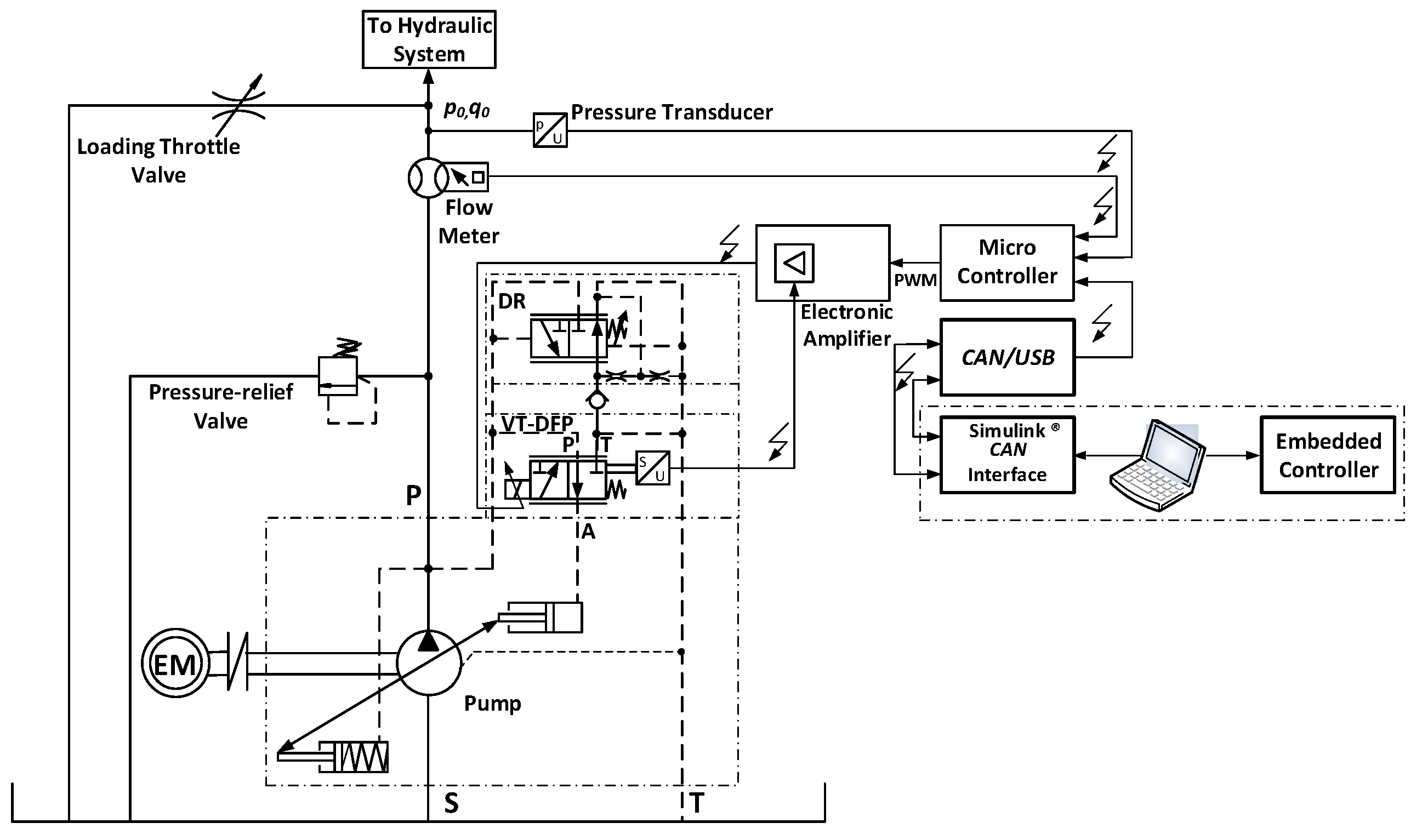
The hydraulic circuit scheme of the developed electro-hydraulic control system for the axial piston pump is depicted in
Figure 1. The system is realized as a laboratory test rig that allows for conducting experimental studies for identification purposes. The detail description of the main components used in the test rig is shown in the authors’ previous work [
13]. The realized solution is based on the open-circuit variable displacement axial piston pump type A10VSO [
16,
17]. The pump is regulated by a proportional electro-hydraulic valve type VT-DFP, which is intended for this type of pump. This valve provides the ability to change the displacement volume of the pump and, hence, the flow rate it delivers to the system. In practice, the valve serves as the pilot electro-hydraulic control of the pump [
25]. In parallel, a conventional hydraulic pressure controller type DR is connected, which serves to decrease the flow rate of the pump when the pressure in the system increases until reaching a value corresponding to its setting. It primarily performs a safety function, but, in combination with an additional valve, can also serve as a power limiter. The used proportional valve is designed for control with an external interface. The external electronic amplifier is VT-5041, which is only used to measure feedback signals and to receive a reference signal from a programmable 32-bit controller type MC012 [
26]. The system software is distributed between the industrial controller and the desktop workstation to allow for rapid prototyping of the different types of identification experiment. The distributed system is based on a real-time communication channel between the PLC and the workstation running a Simulink
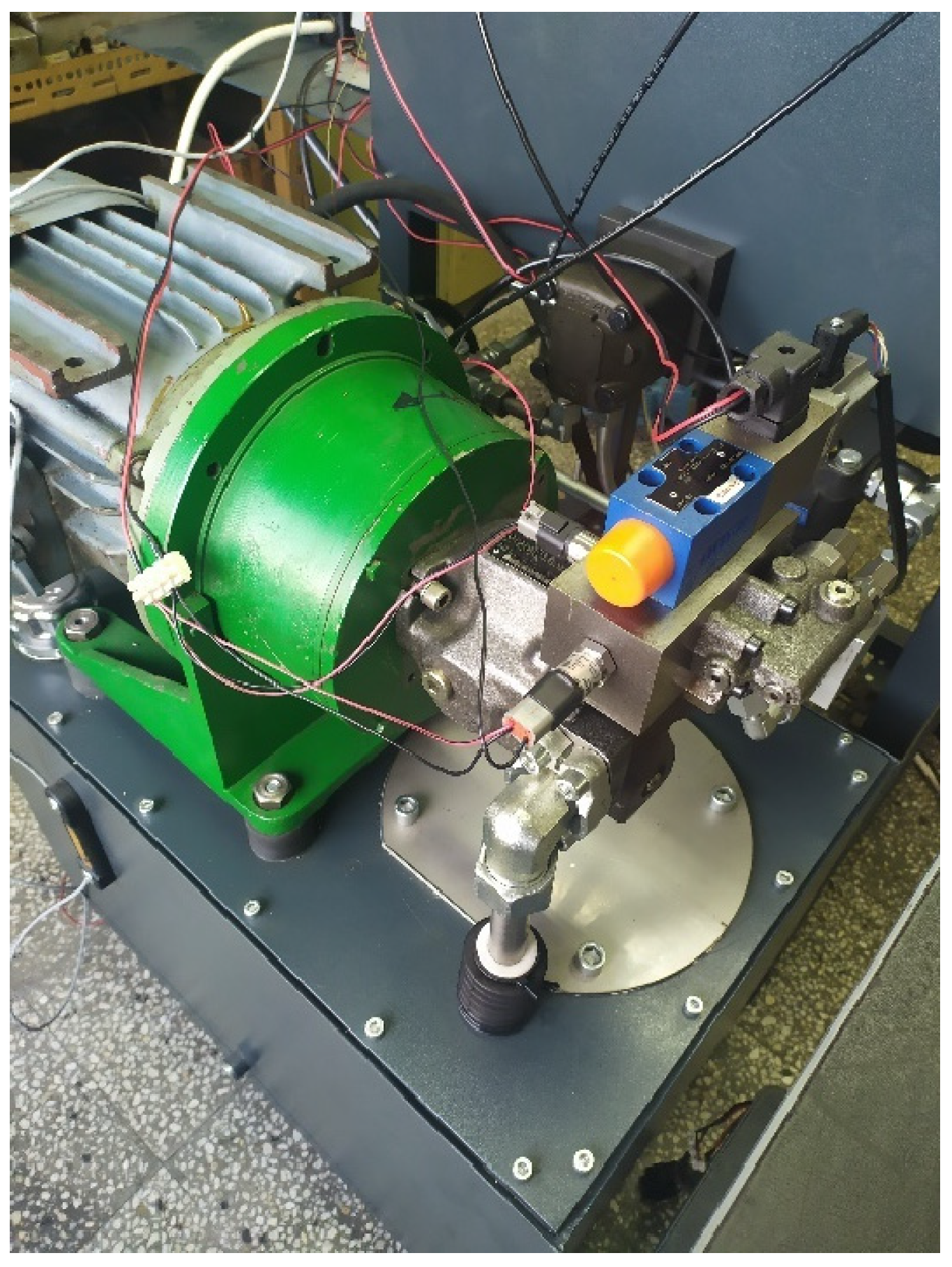
® model. The communication is carried out via USB/CAN network in blocking mode, with a synchronization packet emitted from the industrial controller with a sample time of 10 ms. This sampling period is fast enough to allow precise control of the pressure and flow rate. A photo of the test rig implementation is presented in
Figure 2.
3. Control Design Based on Identified Model
Herein, as example, the
H∞ controller design is performed. To synthesize it, a state space linear mathematical model is needed. Due to the lack of priory information of constructive parameters regarding the axial piston pump, the preferred approach for modelling is to evaluate a “black box”-type model [
27,
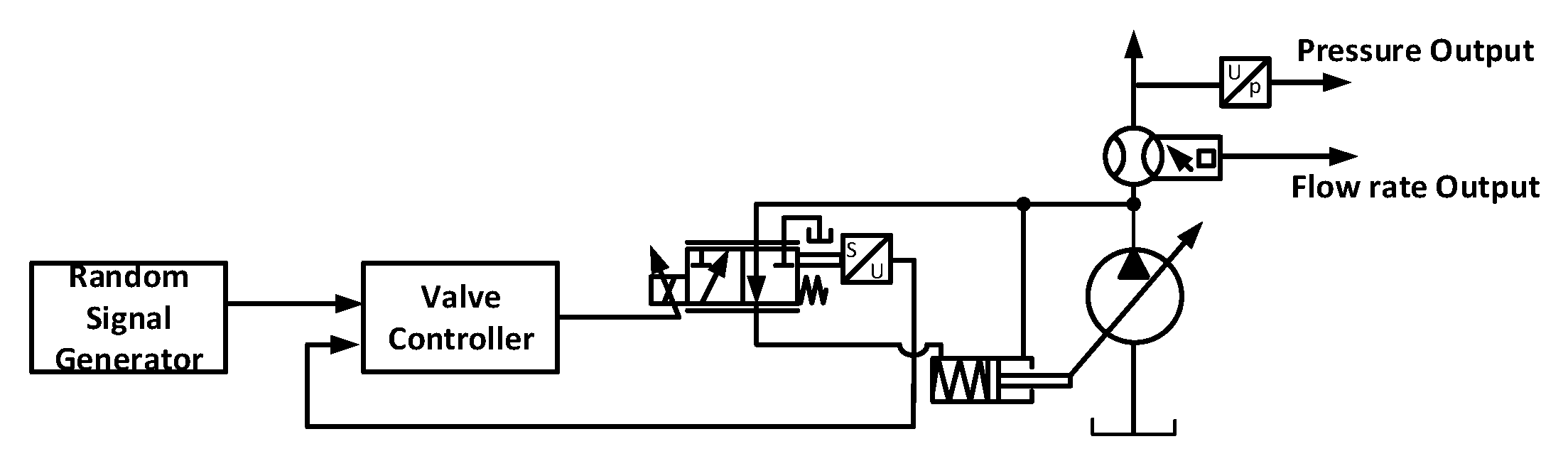
28]. The data acquisition experiment is performed according to scheme presented in
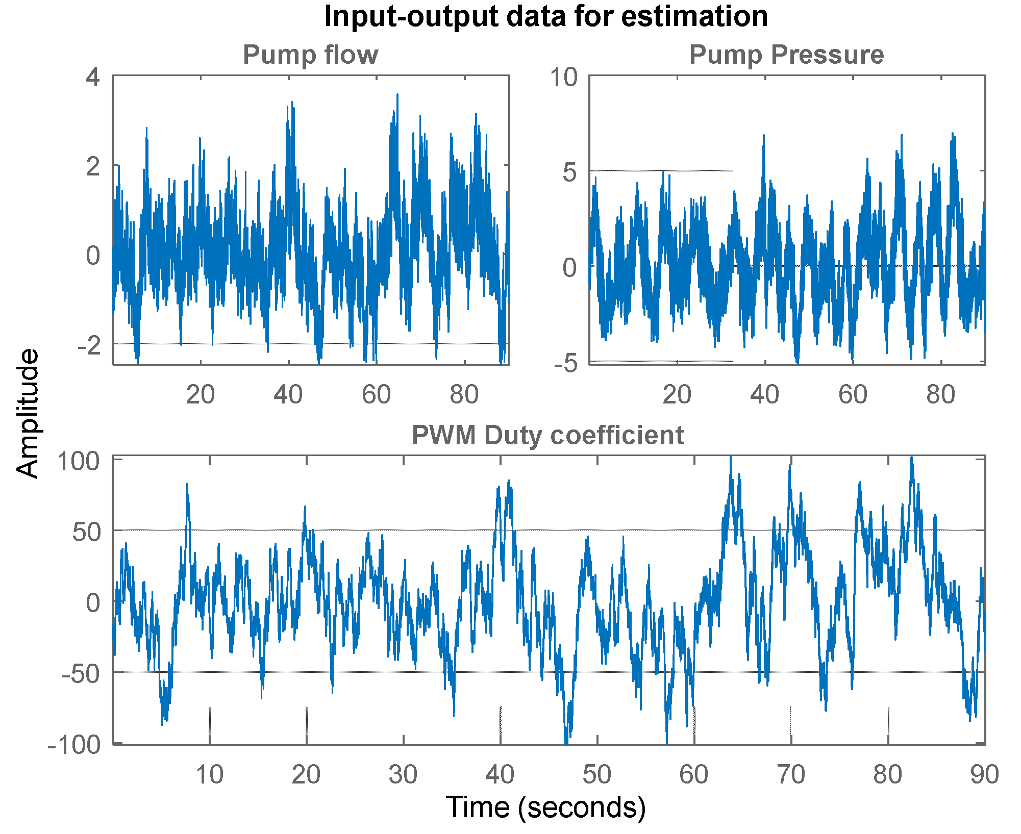
Figure 3. The applied input signal is white Gaussian noise in order to obtain sufficient excitation. As a result, the discrete time data for the output pump flow rate, pressure, and input signal (control action) are measured. In
Figure 4, part of the measured dataset is depicted.
It is supposed that the dynamics of the axial piston pump can be described by a “black box” discrete-time state-space model
where
and
are state and output vectors, respectively;
is the pump flow rate in liters per minute;
is pump output pressure in bars;
is the control signal in millivolts. The real matrices
,
,
,
, and
present system dynamics for a given operating point. The
is the sample time. The residual signal vector
represents the error that occurred between the measurement and model data. It is well-known that if the model is adequate then the residuals are a white Gaussian sequence. The estimation with prediction error method model of the sixth order is adequate, as shown in [
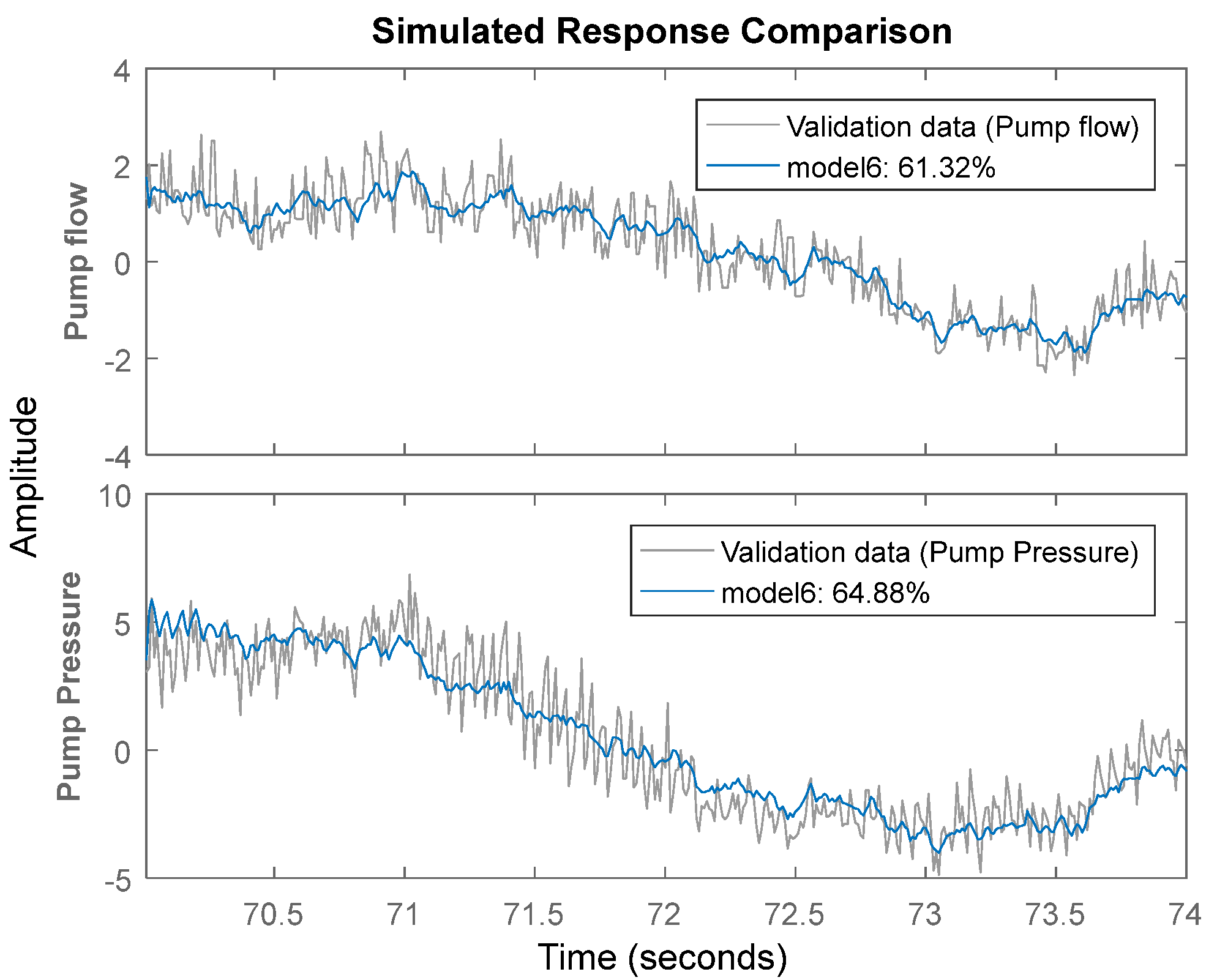
29]. Herein, only some results for its validation are presented. In
Figure 5, the results from the comparison between outputs
of the sixth order model and measured pump flow rate and pressure are presented. As can be seen, the obtained fit for the pump flow rate is approximately 61% and that for pump pressure is 64%, which shows the performance of the estimated sixth order model.
The obtained values for the identified model parameters are
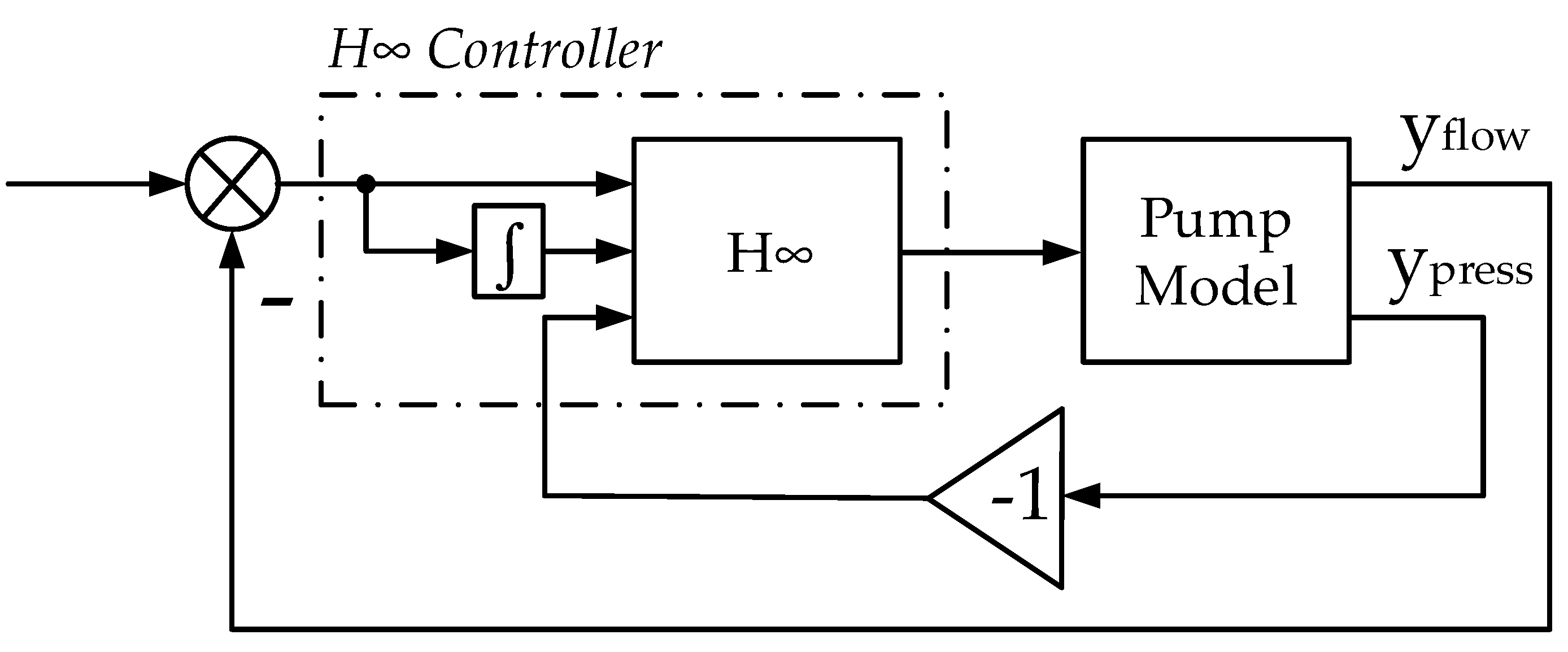
The model (1) is used for
H∞ controller design according to the scheme presented in
Figure 6, where
and
are the transfer functions of performance weighting filters.
As can be seen, the error performance filter
has three inputs that form a control output
as:
where:
is error between desired flow
and measured flow
and
is discrete time integral of
The aim of controller design is to solve the optimization problem
where
is the transfer matrix between performance outputs
and flow reference signal
. It is well-known that, in practice, to achieve prescribed performance conditions is sufficient to find stabilizing controller
[
30], which provides
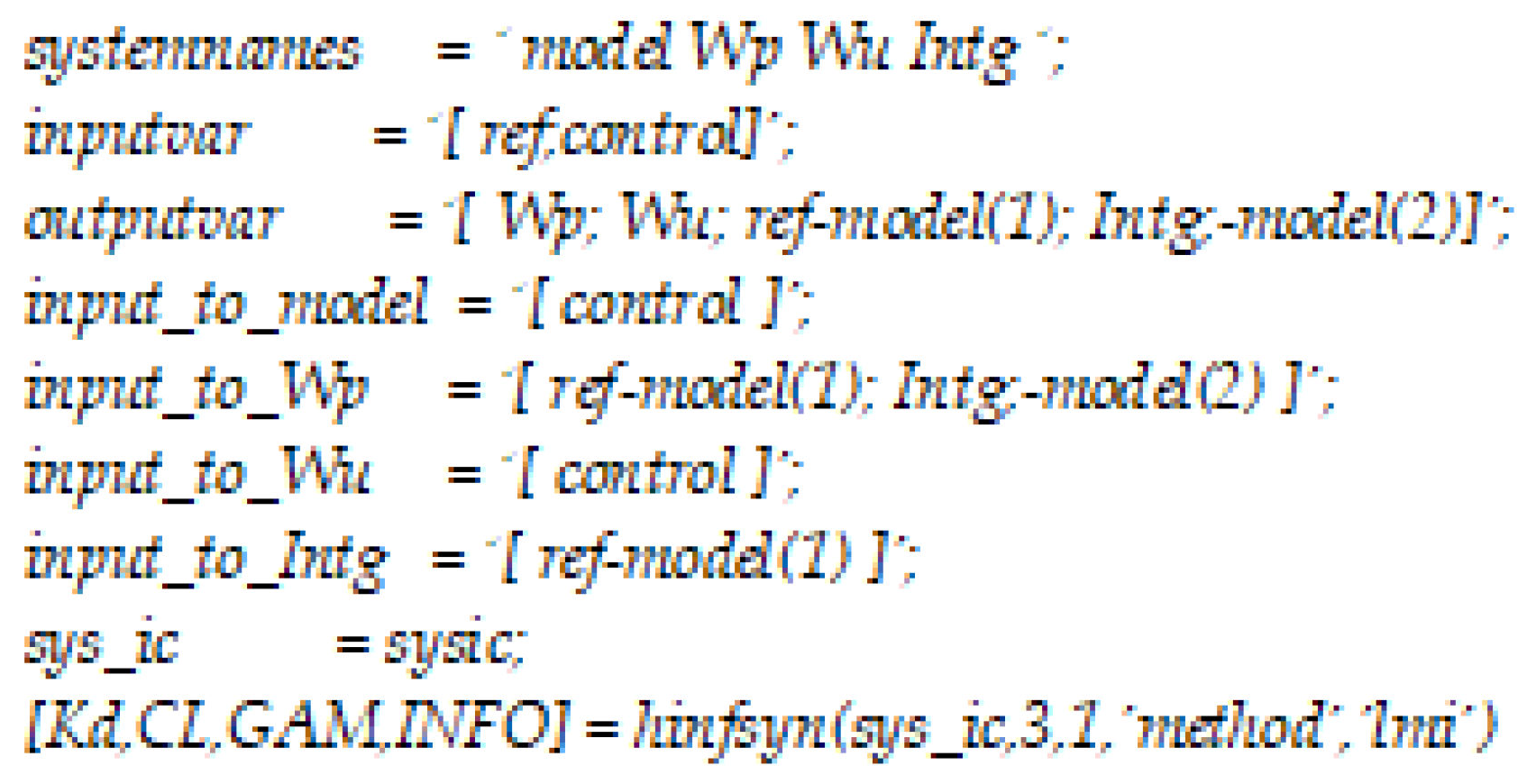
This problem is solved by robust control MATLAB function
hinfsyn [
31]. The design is performed with several different performance weights. The requirements for system output performance and for the shape of the control signal are satisfied for the
H∞ controller obtained with the weighed filters
where
denotes Z-transformation.
The source code for the representation of the extended performance filter plant model and
H∞ controller design is presented in
Figure 7. The result obtained after minimization of (7) closed–loop system’s
H∞ norm is 0.4717, which is smaller than 1. Thus, the prescribed performance conditions are satisfied. The discrete-time state-space description of the
H∞ controller is
where
is the controller state vector and
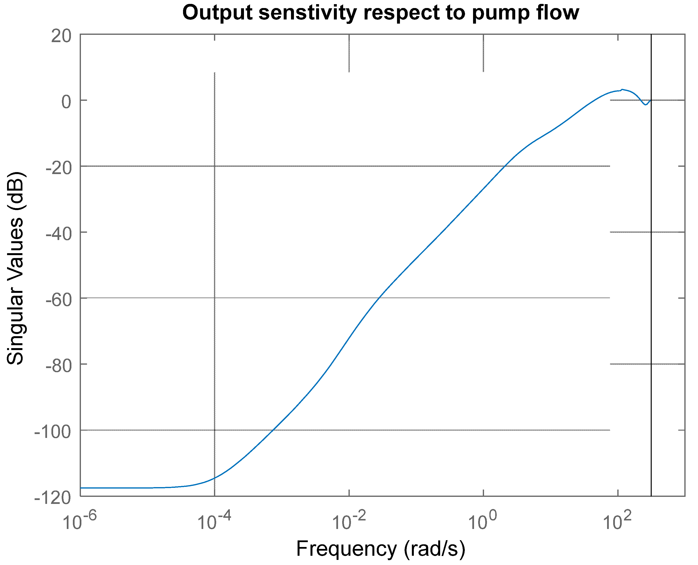
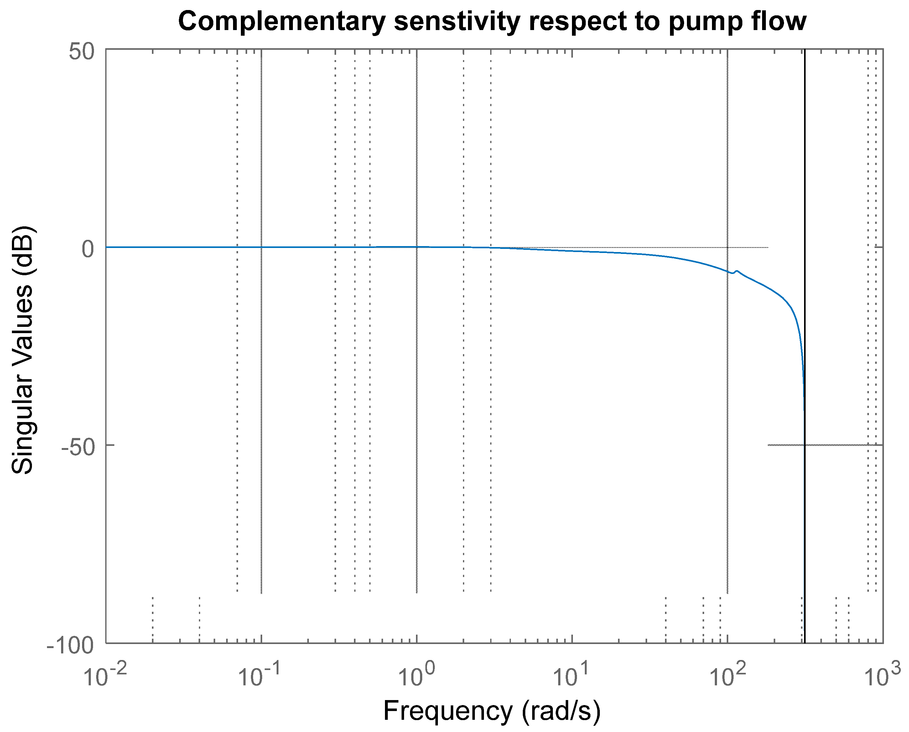
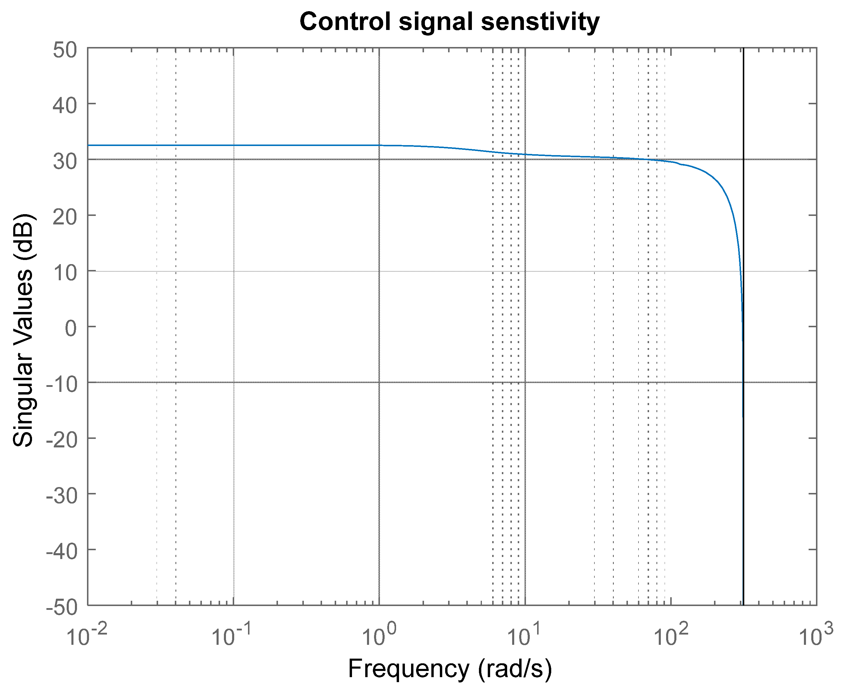
are the controller matrixes. The singular values of output sensitivity, complementary sensitivity, and control signal sensitivity are presented in
Figure 8,
Figure 9 and
Figure 10. As can be seen from
Figure 8, the closed-loop system attenuates load disturbances sufficiently well (for example, the effect of disturbance with frequency 0.001 rad/s is reduced
times). Moreover, the system tracks flow reference signals with frequencies up to 3 rad/s without steady-state error and the closed-loop bandwidth is approximately 12 rad/s, which means that the system dynamic is sufficiently fast (
Figure 9).
Figure 10 shows that the control signal sensitivity to high frequency measurement noise is relatively small, which means that the working mode of the swash plate is admissible. The structure scheme of the control system is presented in
Figure 11.
4. Implementation of System for Rapid Prototyping of Real-Time Control Algorithms
The implementation of a high order real-time control algorithm in embedded platforms is a demanding technical task. Using conventional programming languages such as C or ST (for PLC programming) for the specification of the control algorithm might be error-prone due to the involved matrix arithmetic, hence, extensive testing and formal verification phases are obligatory before actual validation of the control algorithm with the plant. Additionally, hardware requirements of the platform might pose restrictions on the number representation standard (fixed-point or floating point), as well as introduce various rounding and precision errors, which, in some cases, might impact actual stability and performance of the designed controller. Therefore, various approaches for rapid (accelerated) prototyping of the control algorithms exists [
32], depending on the application, hardware platforms, and controller design tools. In our case, we use the MATLAB
®/Simulink environment, which offers several technologies for the simulation of the control algorithm with target hardware and plant, which are more or less bounded to a particular target hardware or application. However, there is no standard library in MATLAB
® for controllers specialized for hydraulic applications such as Danfoss
® MC012-022. Hence, we developed a custom solution to enable a rapid experimental validation of the designed control algorithm. Our rapid prototyping system consists of the following elements:
An embedded program in the MC012-022 developed in Danfoss Plus+1 IDE to support data acquisition from pressure and flow rate sensors attached to the test bench, as well as to generate the control waveforms using PWM for the control valve amplifier;
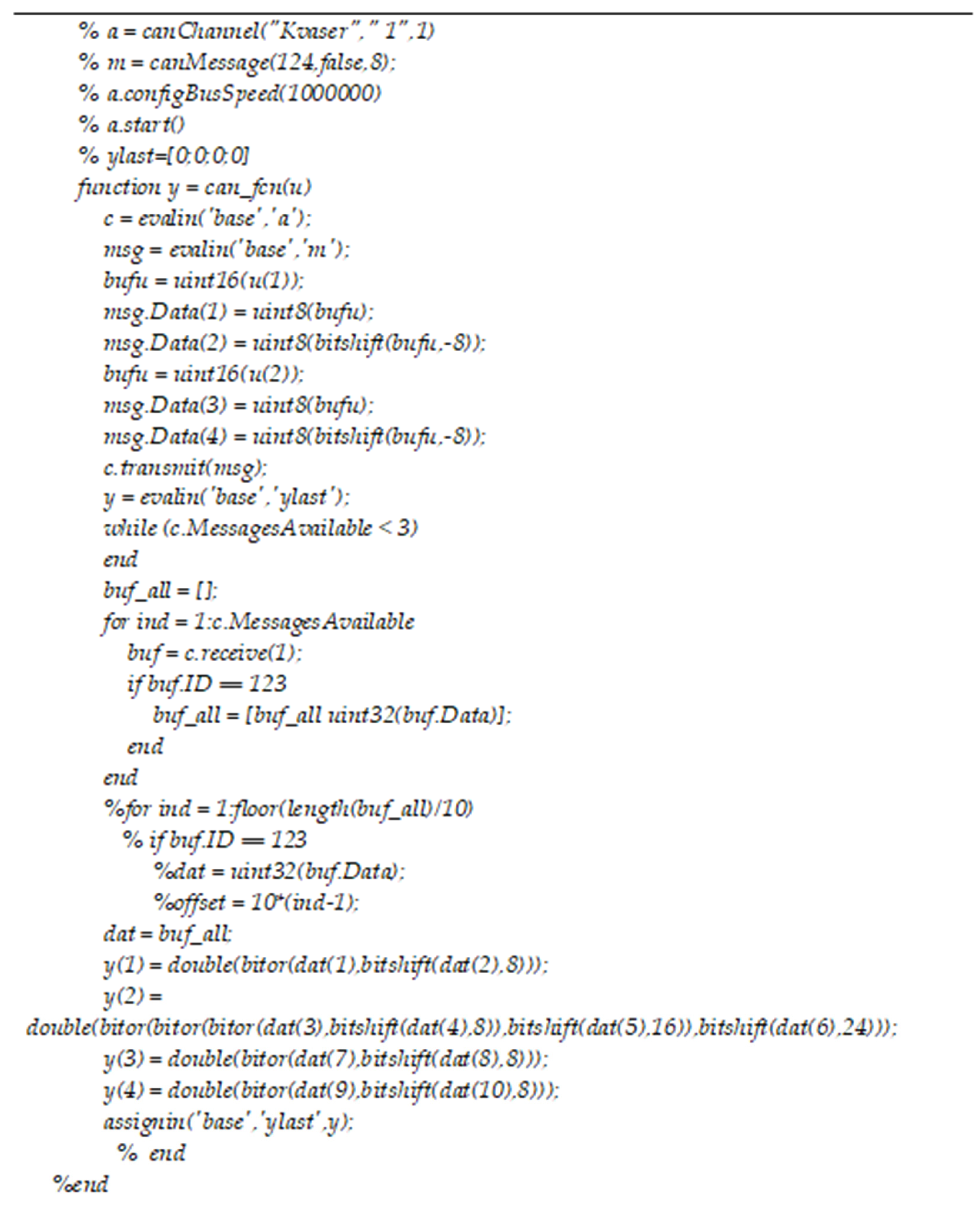
CAN-based communication channel between the microcontroller and the desktop workstation running MATLAB®/Simulink. The channel is supported with a CAN–USB converter on a physical level and respective driver modules in the workstation (Kvaser) and in the microcontroller. We developed a custom communication protocol to enable exchange the signal levels between the Simulink and the microcontroller in real-time;
Simulink communication block, implemented as a m-function (
Figure 12), which can access the CAN driver to handle the real-time communication protocol messages and to synchronize the execution of the host Simulink model with the real-time timestamps of the microcontroller. The microcontroller is responsible for the synchronization by sending data messages on fixed intervals, which, upon reception by host workstation, unblock the execution of the Simulink model for one sample interval. After that, the execution of the model is blocked again until the next message is received, hence, the timestamps of the Simulink diagram are synchronized with the time of the microcontroller;
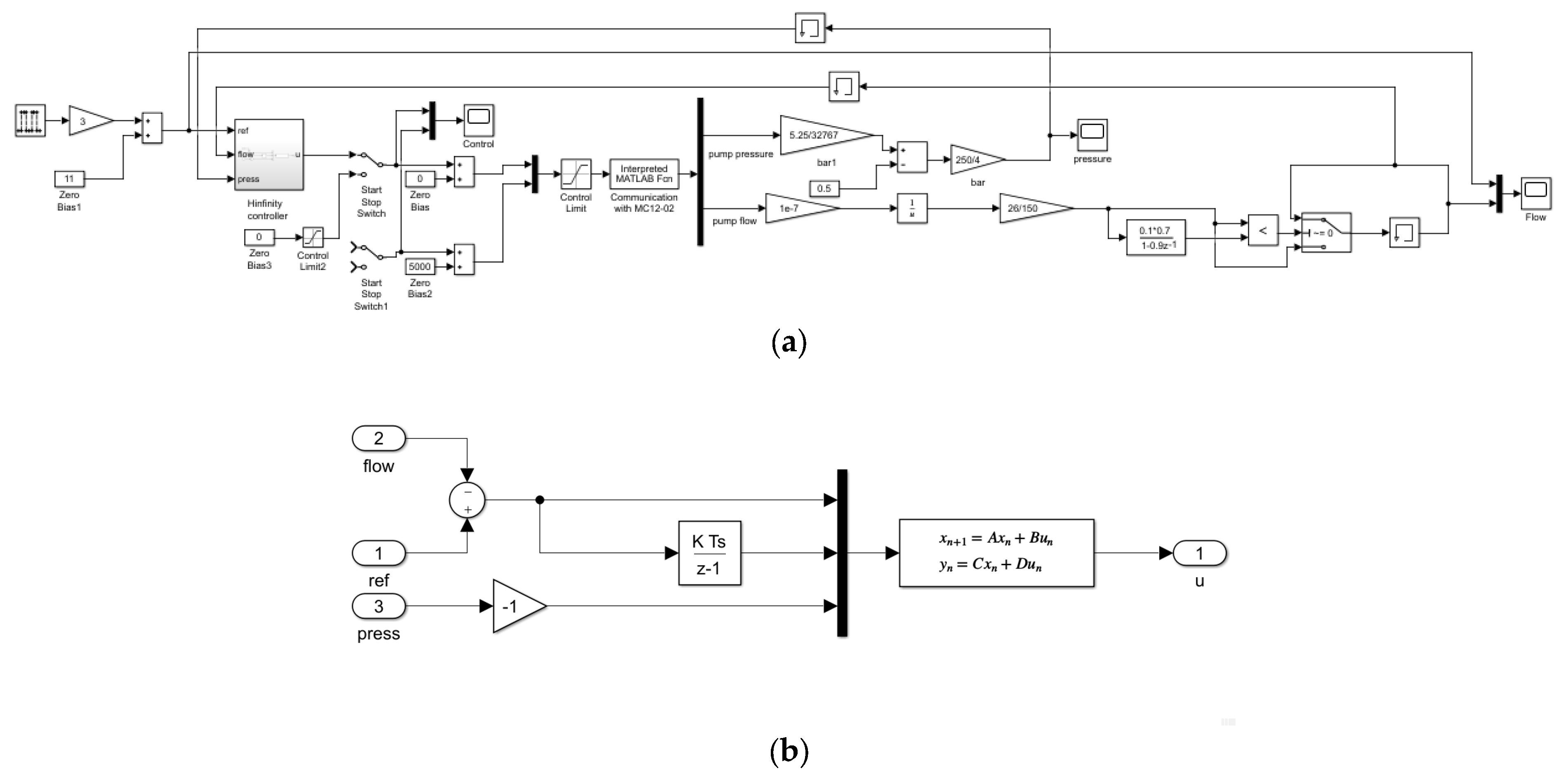
A host Simulink model (
Figure 13a), containing the block diagram of the designed control algorithm. The detailed diagram of
H∞ controller is presented in
Figure 13b. Since the time of the host Simulink model is synchronized to the microcontroller, the control algorithm executes in real-time, calculating the actuator signal in each time instant when the data from testbench sensors arrive. In this way, the implementation of the control algorithm is maximally approaching the closed-loop simulation models used in the process of controller design. Of course, instead of a plant model, the actual pump loading test bench is connected and powered. Also, the communication protocol introduces one step delay, which is not present during the controller design.
The purpose of the control system is to control the pump swash plate swivel angle in order to keep the flow rate at a predefined reference level. The reference signal for our experiments is selected as periodic square wave signal with period of 2.5 s. The square waveform as an input to the closed-loop system allows for the excitation of all frequencies of the loop, to evaluate its performance metrics. The key requirement for the closed-loop systems is the achievement of 0 steady-state error, i.e., the mean value of the flow rate to be equal to the commanded value. Another requirement is the settling time, or how fast the output of the system reaches its steady state. That metric is important not only for reaction time to changes in the reference signal, but also for the disturbance rejection capabilities of the system. Therefore, if the settling time is short, in an event of an external disturbance, such as instantaneous change of external loads or valve switching, the pump will respond to that disturbance seamlessly.
To evaluate the control system performance in the full operating range of the pump, we tested the closed-loop for four different loading settings. The system loading is commanded by changing the opening of the loading throttle valve (
Figure 1). The level of throttle valve opening can be precisely selected using a micrometer scale between 2 to 5 mm. With the increase in the opening of the throttle valve, the loading of the system is decreased, which can be seen in the pressure output of the pump. Another specific aspect when testing the pump at different loading conditions is that the permissible range of flow rate regulation is changing due to the limitations of the mechanical and electrical components. Therefore, the reference levels used in the following figures are different depending on the selected loading.
Figure 14 show the pump flow rate regulation for minima opening of the throttle valve, corresponding to the highest loading of the pump, indicated by highest output pressure. The reference signal for the flow rate is commanded between 14 and 17 L/min. It is seen that the flow rate is tracking the reference with settling time below 100 ms. The settling time is shorter when the flow rate is increased, being as small as 20 ms. The settling time is longer when the flow rate is decreased from the higher to lower level, being around 100 ms. This can be explained with dynamical asymmetry of the swashplate inside the pump for increasing or decreasing swivel angle, due to the unidirectional spring attached at the swashplate. This asymmetry is excited at higher loads when the output pressure of the pump is reflected back on the swash plate. In the experimental data, some amount of oscillating/noise artifacts are present, which is discussed in the following paragraphs.
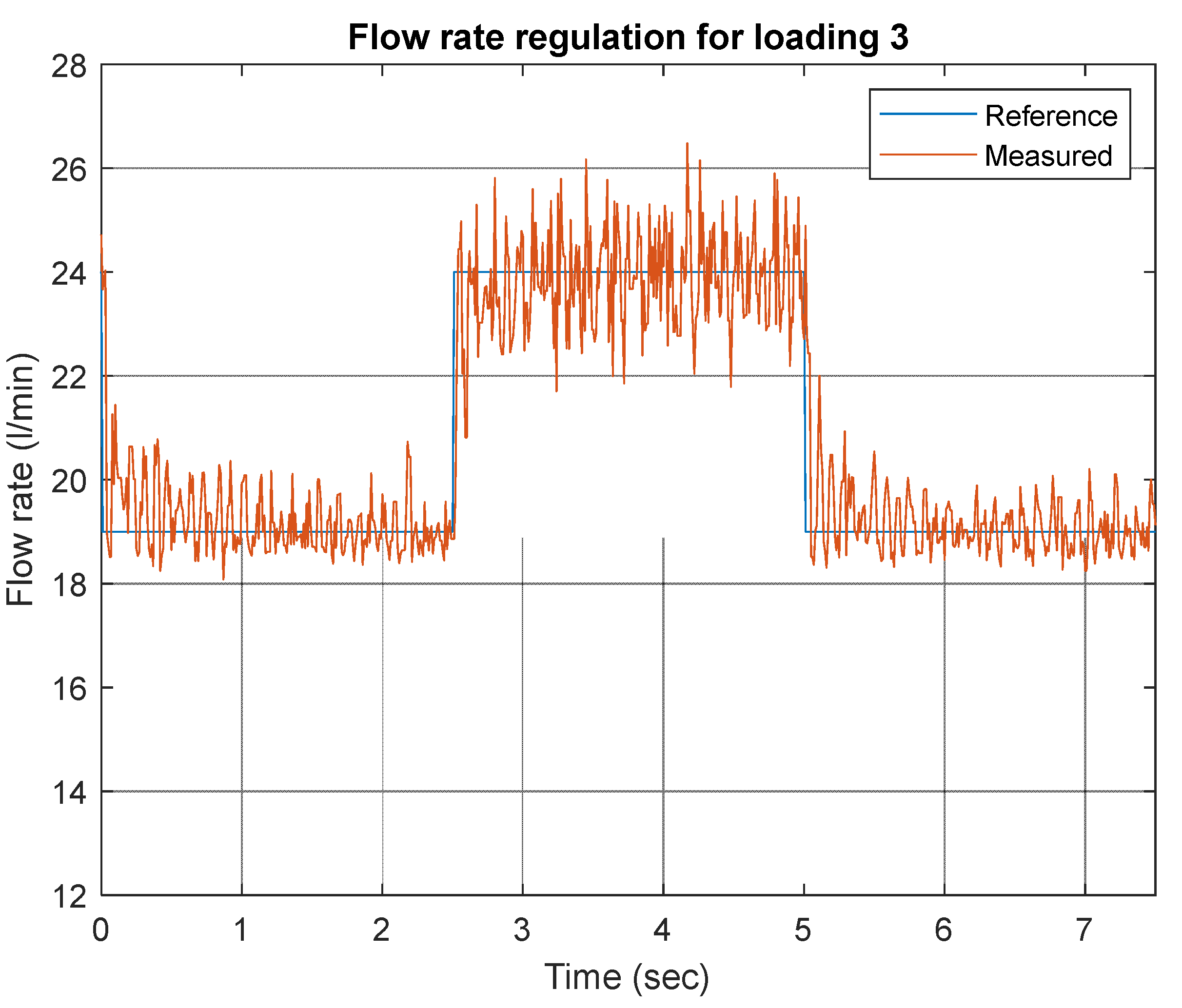
In
Figure 15, the closed-loop response for throttle valve opening of 3 mm is presented, which is still a high loading to the system. In such loading conditions, the closed-loop shows even better performance in regards to settling time, which is in the range under 50 ms. The reference flow rate is in the range of 19 to 24 L/min. A slightly slower response can be seen when the reference flow rate is reduced, as the mean level of the flow rate signal is above the reference for a couple of noise periods. The noise oscillations around the reference are still present, but their amplitude is partially reduced. With the increase in the flow rate, the amplitude of the noise is increased. It can be judged that frequency range of the noise signal is constant and independent of the loading conditions, hence, it can be attributed to the nature of the flow rate instrument, which is an orbital volumetric hydraulic machine introducing high frequency discontinuities in the flow.
The next figures are focused on experiments with lower loading of the pump, which allows it to reach its nominal (rated) parameters of a flow rate of about 26 L/min. In this mode of control, the output pressure of the pump is also reduced to about 20 to 30 bars. During the experiments, there is clear audible difference in emitted acoustic noise from the testbench when the pump works at a higher load (2 or 3 mm opening of the throttle valve) vs the situation when the pump works at lower loads (4 or 5 mm opening). This can be confirmed with the conduction of further energy analysis accounting for the power throughput of the system. With increasing the load, the heating of the pump is more pronounced, especially at the highest loading of 2 mm throttle valve opening. There are some instants when the pressure-relief valve threshold of 100 bar might be reached, therefore, the relief valve also becomes part of the system dynamic, further disturbing the open-loop mathematical model.
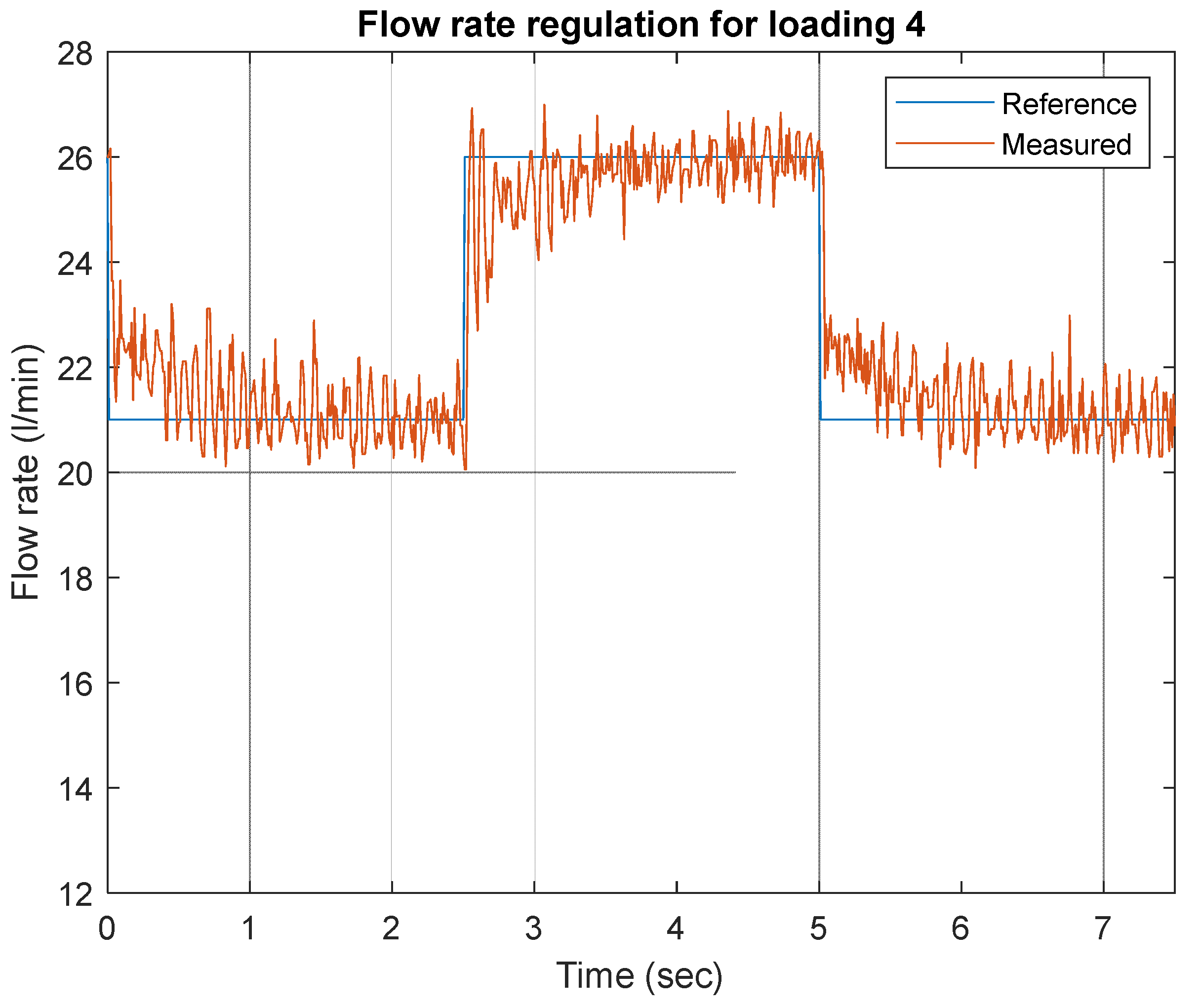
Figure 16 presents the closed-loop response when throttle valve is opened at 4 mm, where it is evident that the closed-loop system works, with zero steady-state error obtained as a mean value of the noisy flow rate signal. The settling time in case of this lower loading is slightly degraded compared to the previous higher loading experiments. The settling time is about 0.5 s when flow rate reference steps from 21 to 26 L/min, and about 0.8 s when the reference drops back to 22 L/min. As we know from the pump equations, the model of the system is nonlinear, which will manifest with variable dynamic responses for different loading conditions. That circumstance also affects the controller design, since we use a linear control approach, which requires a linearized model of system dynamics. In our case, the linearized model is obtained with the help of statistical identification procedures for the data set corresponding to the highest loading conditions, to reflect the highest gain of the possible pump dynamical responses. As was noted, for the highest loading the pressure acting in the system is maximal, ranging between 80 to 120 bar, and, hence, generates maximal forces acting on the pump elements, which is reflected in the mathematical model frequency response as an increased open-loop gain. From control theory, we know that when the open-loop frequency response is elevated, it can easily make the system unstable given a fixed linear controller, therefore, the highest loading conditions in our case represent the worst-case scenario for system operation. In addition, as noted above, during the highest loading with elevated pressure, the pressure-relief valve begins to participate in the system dynamics, which can further complicate the open-loop response. With our controller being designed for the worst-case loading conditions, we can expect that its performance might be slightly degraded when the open-loop gain is reduced with lowering the loading with increasing the throttle valve opening, however, keeping system stability is prioritized. That is why the settling time of the transient response presented in
Figure 16 is larger than that depicted in
Figure 15.
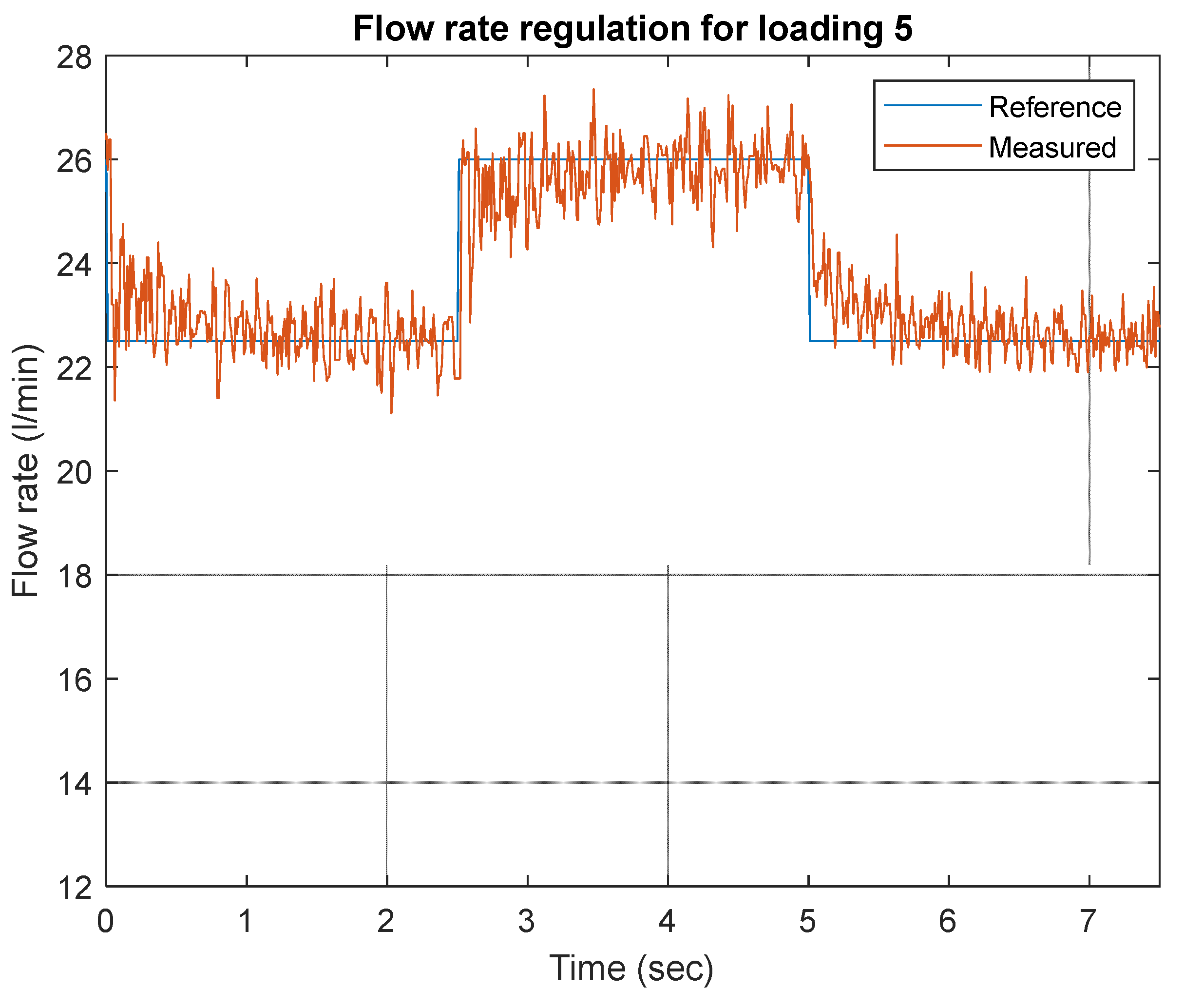
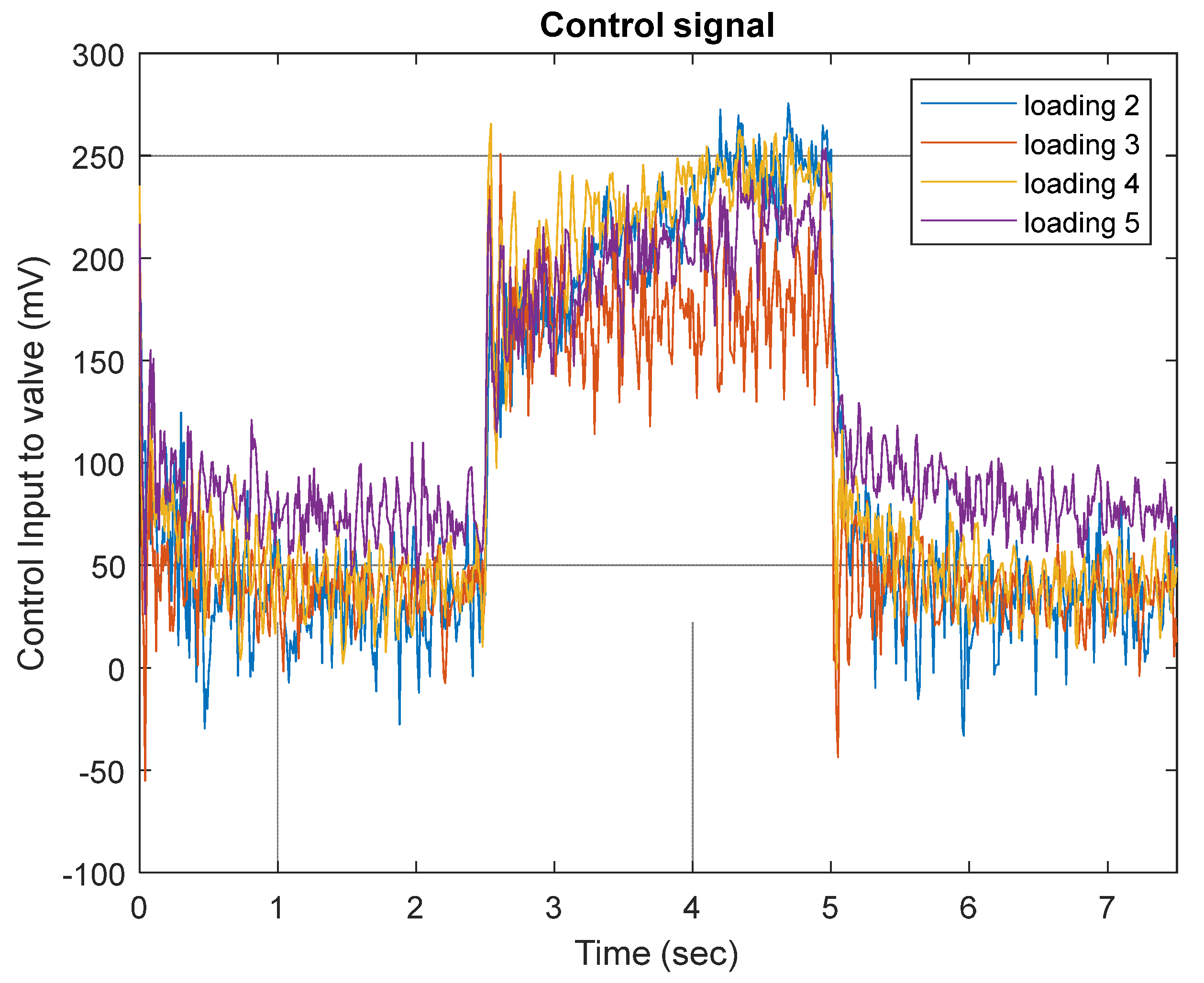
Figure 17 shows the response of the closed-loop for the most relaxed loading conditions when the throttle valve is set at 5 mm opening. The performance of the system is similar to the previous loading conditions of 4 mm opening. However, in this experiment, the reference for the pump flow rate is from 22.5 to 26 L/min. In
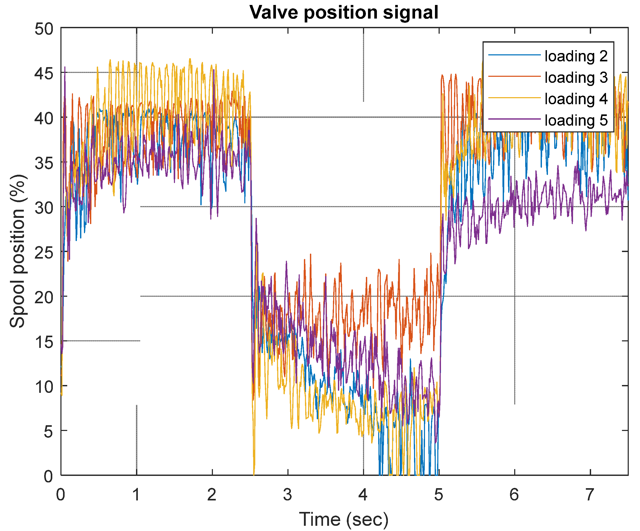
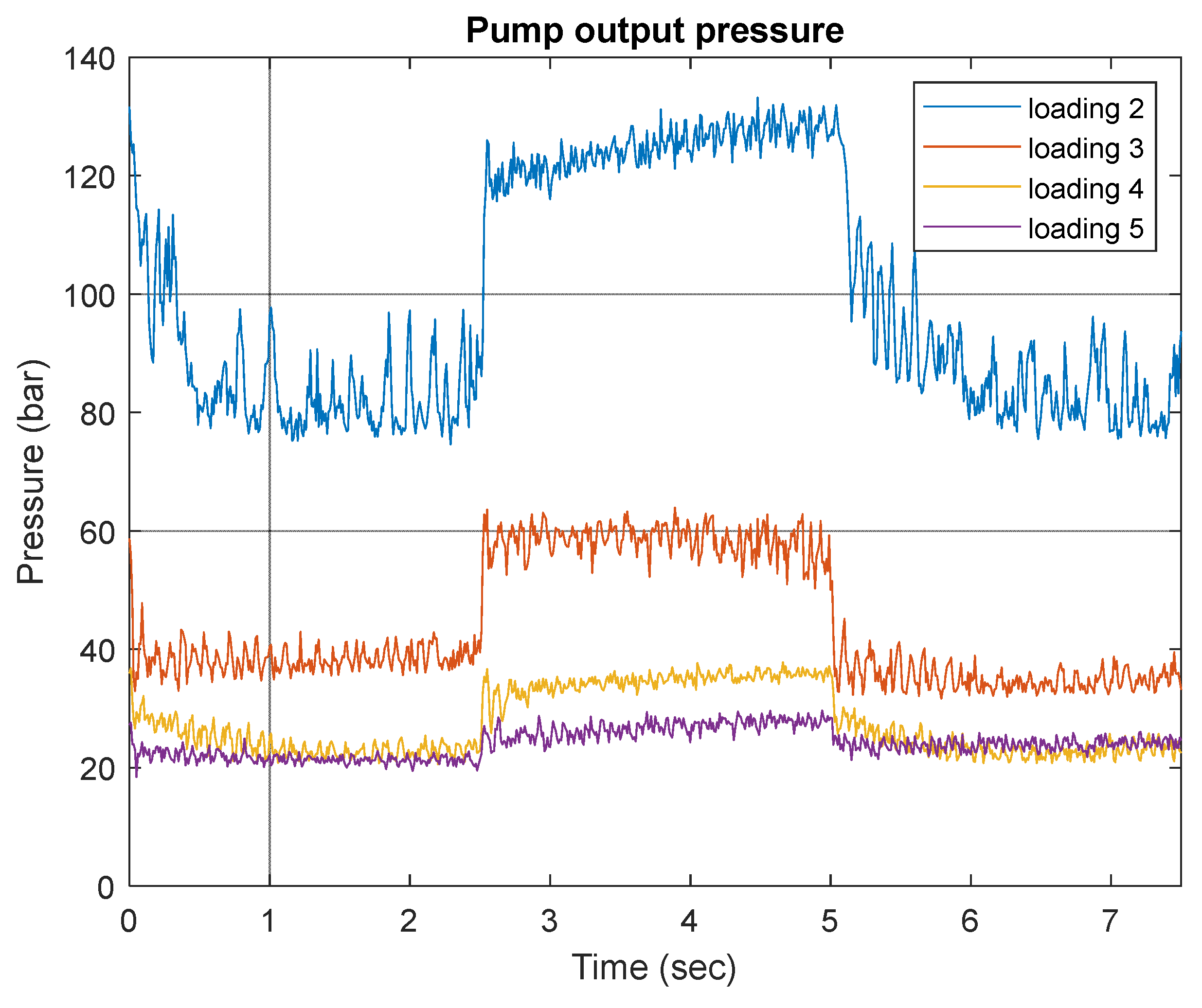
Figure 18 and
Figure 19 the control signal and measured proportional spool valve position are depicted for various investigated loading conditions. As can be seen from both figures, the shape of the control signal corresponds to the measured spool valve positions in all loading modes. This, once again, confirms control system performance. The variation of pump pressure output during different loading conditions is depicted in
Figure 20.


