
A Bond-Based Peridynamic Model with Matrix Plasticity for Impact Damage Analysis of Composite Materials

Abstract
:1. Introduction
2. Peridynamic Modeling for Composite Materials
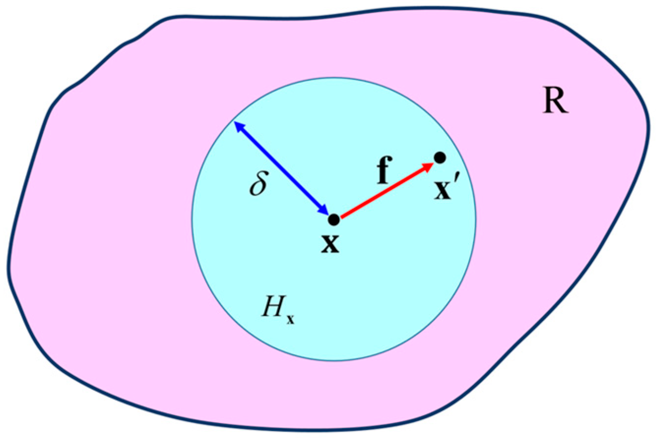
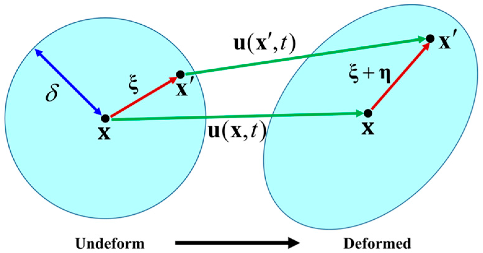
2.1. Bond-Based Peridynamic Theory
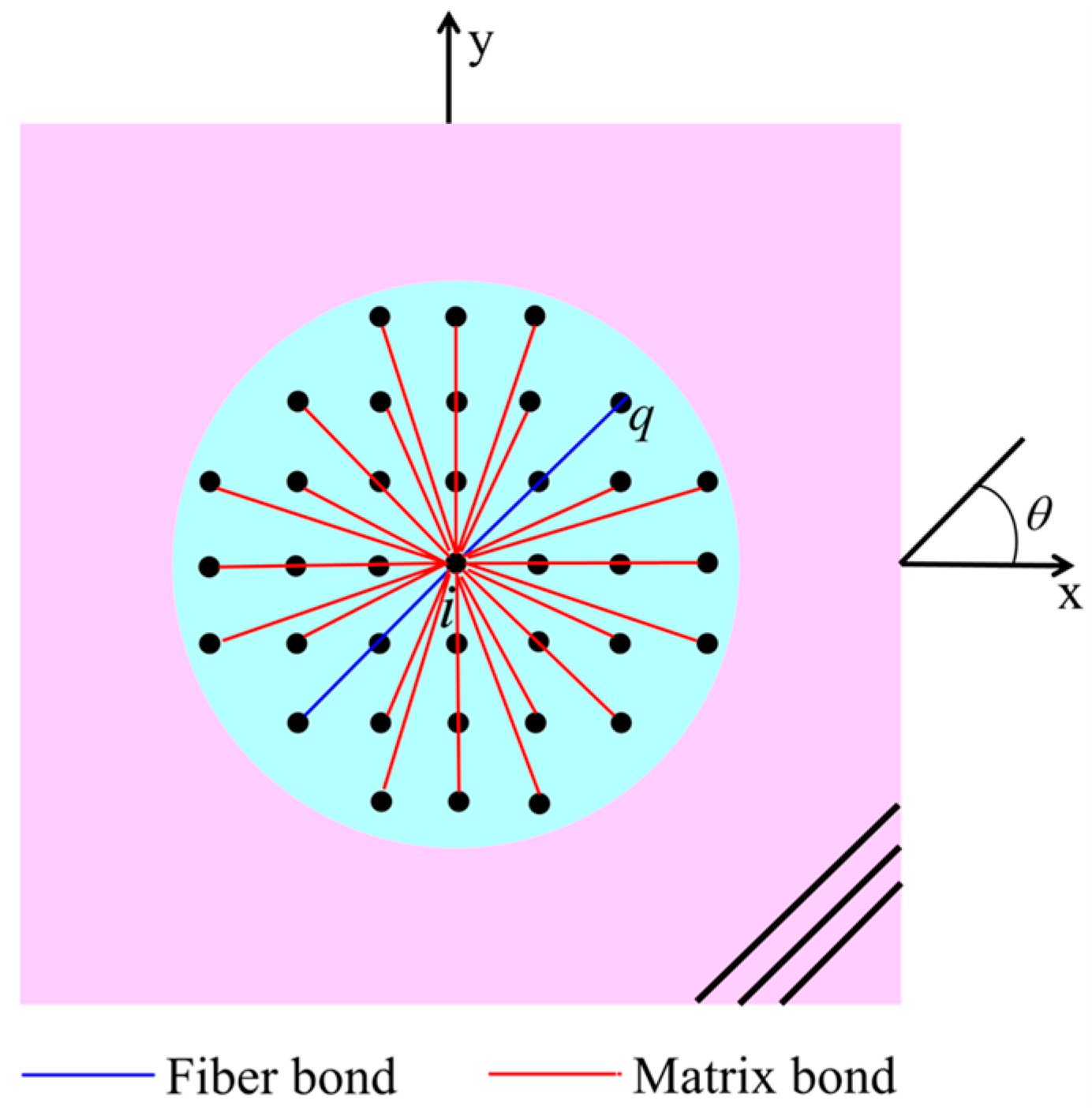
2.2. PD Modeling of a Lamina
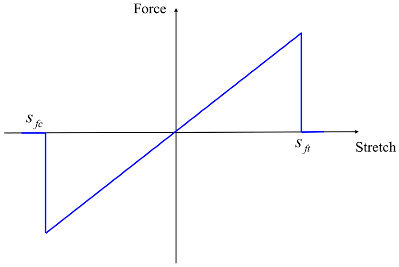
2.2.1. PD Model of the Fiber Bond
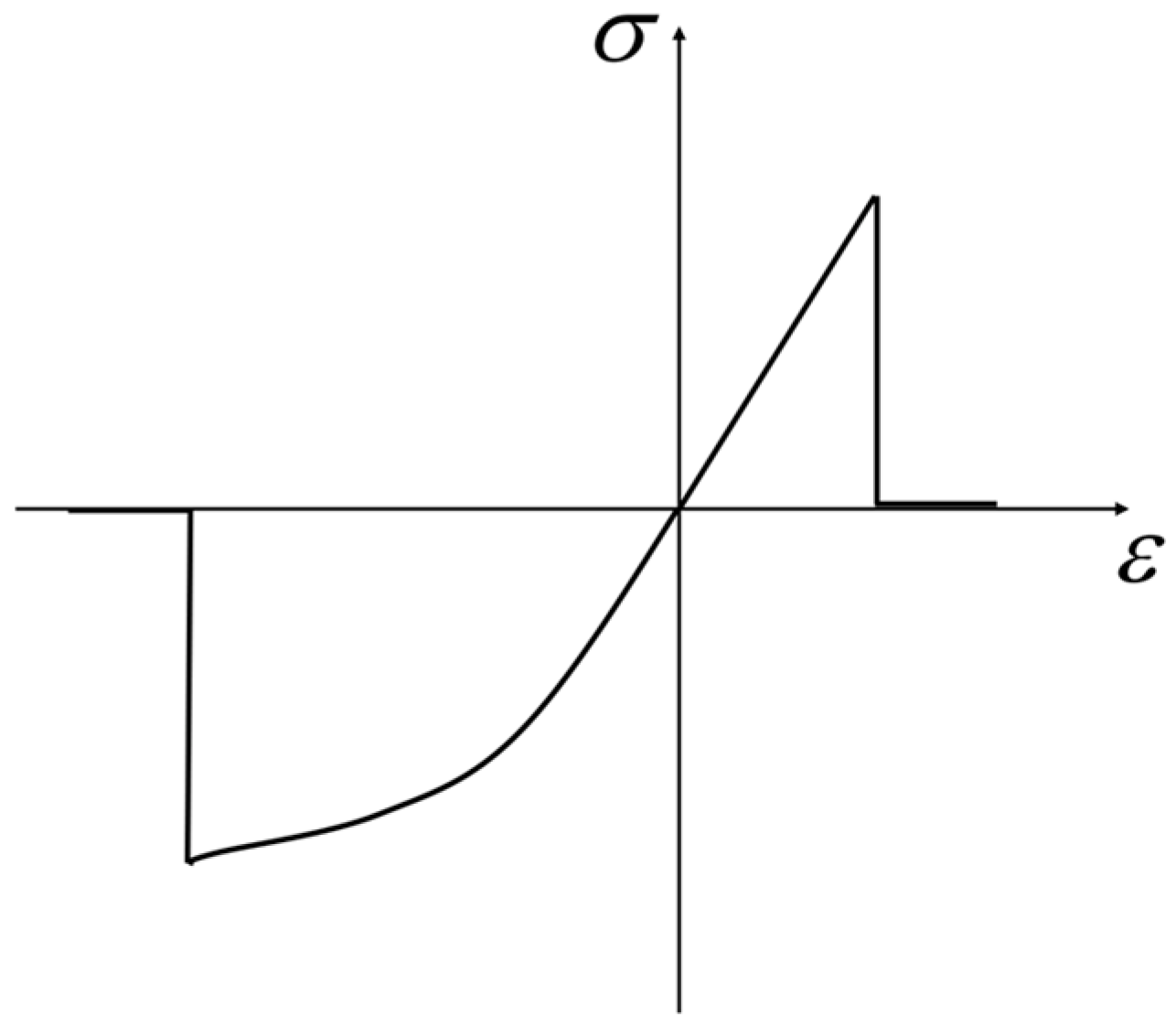
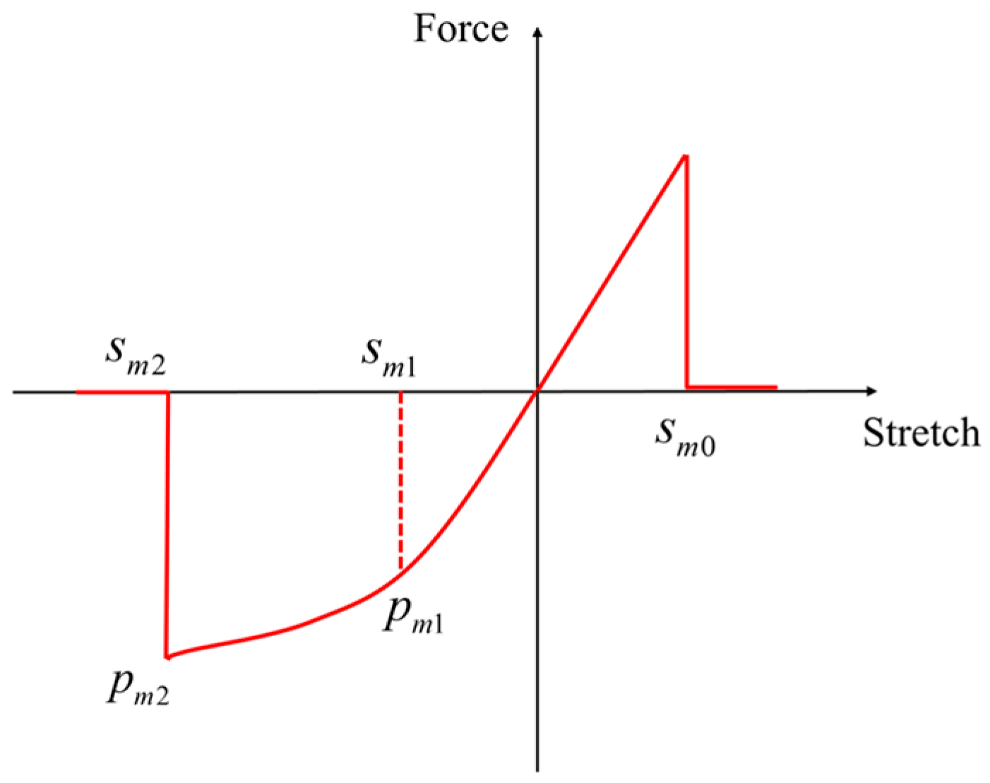
2.2.2. PD Model of the Matrix Bond
Tensile Loading
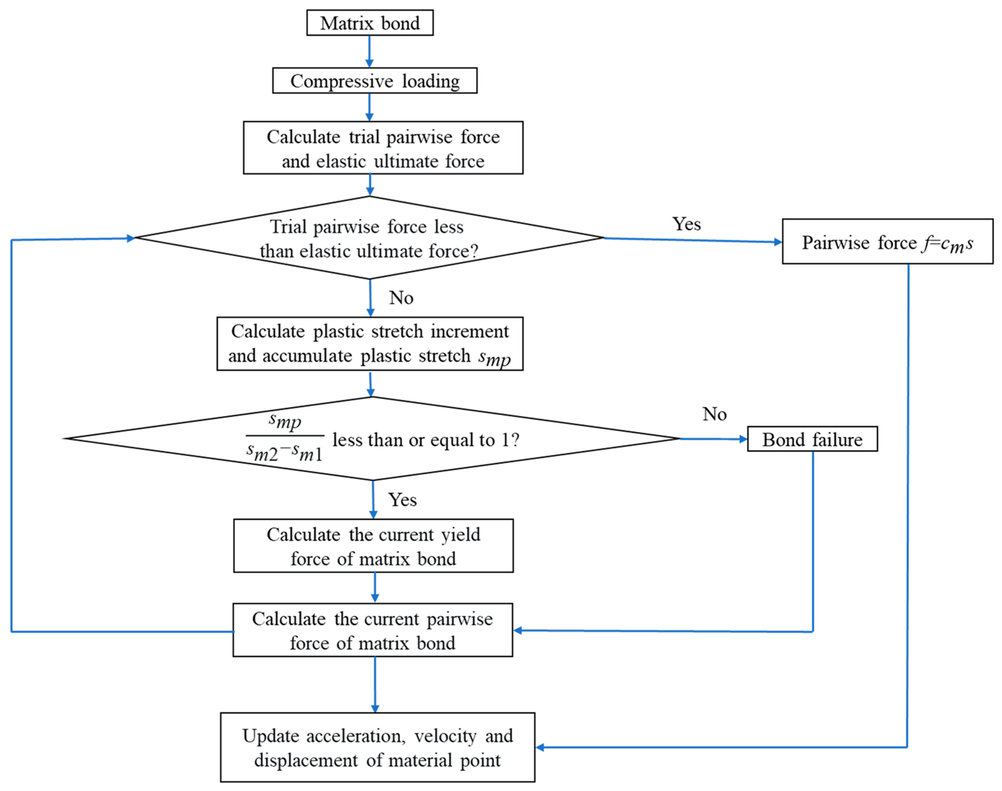
Compressive Loading
Yield Criterion
2.2.3. Determination of Parameters in the Model of a Lamina
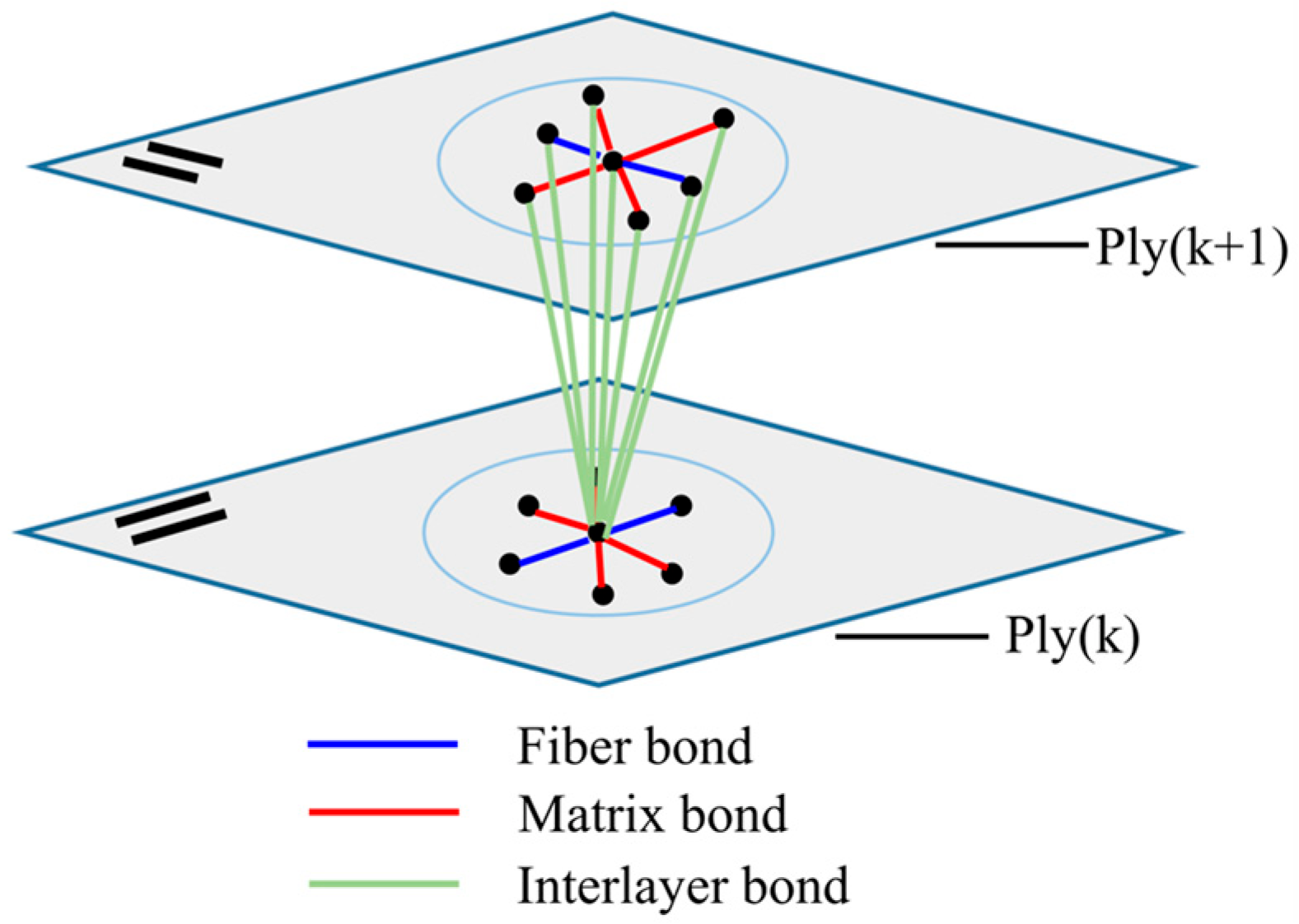
2.3. PD Modeling of Laminates
2.3.1. PD Model of the Interlayer Bond
Tensile Loading
Compressive Loading
2.3.2. Determination of Parameters of the Interlayer Bond
3. Numerical Implementation
3.1. Solving Method
3.2. Pairwise Force Updating Algorithm
4. Numerical Simulations
4.1. Convergence Analysis
4.2. Verification
4.3. Initiation and Propagation of Damage
4.4. Damage Pattern under Different Impact Velocities
4.5. Impact Resistance with Different Stacking Sequences
5. Conclusions
- The developed bond-based peridynamic model can accurately describe the impact-induced damage behavior and evolution of fiber-reinforced composite materials. The PD simulation results for impact damage showed a good match with the experimental phenomena.
- The damage to composite laminates under impact loading is distributed and propagated along the fiber orientation, which shows significant anisotropy.
- The damage to composite laminates will become more and more severe with the increase in impact velocity. Compared with a low-impact velocity, the damage to the rear surface of laminates is more serious under high-impact velocity, and a strip of delamination is formed along the fiber orientation.
- The stacking sequence has a distinct effect on the impact resistance of composite laminates under the same impact velocity. For the angle ply laminate, increasing the fiber layup orientation will significantly improve its impact resistance.
Author Contributions
Funding
Institutional Review Board Statement
Informed Consent Statement
Data Availability Statement
Conflicts of Interest
References
- Gower, H.L.; Cronin, D.S.; Plumtree, A. Ballistic impact response of laminated composite panels. Int. J. Impact Eng. 2008, 35, 1000–1008. [Google Scholar] [CrossRef]
- Naik, N.K.; Doshi, A.V. Ballistic impact behaviour of thick composites: Parametric studies. Compos. Struct. 2008, 82, 447–464. [Google Scholar] [CrossRef]
- Reddy, P.R.S.; Reddy, T.S.; Madhu, V.; Gogia, A.K.; Rao, K.V. Behavior of E-glass composite laminates under ballistic impact. Mater. Des. 2015, 84, 79–86. [Google Scholar] [CrossRef]
- Yang, Y.Q.; Zhang, L.; Guo, L.C.; Zhang, W.; Zhao, J.Z.; Xie, W.B. Dynamic response and research of 3D braided carbon fiber reinforced plastics subjected to ballistic impact loading. Compos. Struct. 2018, 206, 578–587. [Google Scholar] [CrossRef]
- Hoffman, O. The brittle strength of orthotropic materials. J. Compos. Mater. 1967, 1, 200–206. [Google Scholar] [CrossRef]
- Hashin, Z.; Rotem, A. A fatigue failure criterion for fiber reinforced materials. J. Compos. Mater. 1973, 7, 448–464. [Google Scholar] [CrossRef] [Green Version]
- Tsai, S.W.; Wu, E. A general theory of strength for anisotropic materials. J. Compos. Mater. 1971, 5, 58–80. [Google Scholar] [CrossRef]
- Pinho, S.T.; Iannucci, L.; Robinson, P. Physically-based failure models and criteria for laminated fiber-reinforced composites with emphasis on fiber kinking. Compos. Part A Appl. Sci. Manuf. 2006, 37, 63–73. [Google Scholar] [CrossRef] [Green Version]
- Donadon, M.V.; Almeida, S.F.; Arbelo, M.A.; Faria, A.R. A three-dimensional ply failure model for composite structures. Int. J. Aerosp. Eng. 2015, 4, 1–22. [Google Scholar] [CrossRef] [Green Version]
- Vogler, M.; Rolfes, R.; Camanho, P.P. Modeling the inelastic deformation and fracture of polymer composites. Mech. Mater. 2013, 59, 50–64. [Google Scholar] [CrossRef]
- Batra, R.C.; Gopinath, G.; Zheng, J. Damage and failure in low energy impact of fiber-reinforced polymeric composite laminates. Compos. Mater. 2012, 94, 540–547. [Google Scholar] [CrossRef]
- Davila, C.G.; Camanho, P.P.; Rose, C.A. Failure criteria for FRP laminates. J. Compos. Mater. 2005, 39, 323–345. [Google Scholar] [CrossRef]
- Camanho, P.P.; Davila, C.G.; Pinho, S.T.; Iannucci, L.; Robinson, P. Prediction of in situ strengths and matrix cracking in composites under transverse tension and in-plane shear. Compos. Part A Appl. Sci. Manuf. 2006, 37, 165–176. [Google Scholar] [CrossRef] [Green Version]
- Pinho, S.T.; Darvizeh, R.; Robinson, P.; Iannucci, L. Material and structural response of polymer-matrix fiber-reinforced composites. J. Compos. Mater. 2012, 46, 2313–2341. [Google Scholar] [CrossRef]
- Aminjikarai, S.B.; Tabiei, A. A strain-rate dependent 3-D micromechanical model for finite element simulations of plain weave composite structures. Compos. Struct. 2007, 81, 407–418. [Google Scholar] [CrossRef]
- Menna, C.; Asprone, D.; Caprino, G.; Lopresto, V.; Prota, A. Numerical simulation of impact tests on GFRP composite laminates. Int. J. Impact Eng. 2011, 38, 677–685. [Google Scholar] [CrossRef] [Green Version]
- Sosa, J.C.; Phaneendra, S.; Munoz, J. Modelling of mixed damage on fibre reinforced composite laminates subjected to low velocity impact. Int. J. Damage Mech. 2013, 22, 356–374. [Google Scholar] [CrossRef] [Green Version]
- Kumar, D.; Roy, R.; Kweon, J.H.; Choi, J.H. Numerical modeling of combined matrix cracking and delamination in composite laminates using cohesive elements. Appl. Compos. Mater. 2016, 23, 397–419. [Google Scholar] [CrossRef]
- Mousavi, M.V.; Khoramishad, H. Investigation of energy absorption in hybridized fiber-reinforced polymer composites under high-velocity impact loading. Int. J. Impact Eng. 2020, 146, 103692. [Google Scholar] [CrossRef]
- Kilic, B.; Madenci, E. Coupling of peridynamic theory and the finite element method. J. Mech. Mater. Struct. 2010, 5, 707–733. [Google Scholar] [CrossRef] [Green Version]
- Oterkus, E.; Madenci, E.; Weckner, O.; Silling, S.; Bogert, P. Combined finite element and peridynamic analyses for predicting failure in a stiffened composite curved panel with a central slot. Compos. Struct. 2012, 94, 839–850. [Google Scholar] [CrossRef] [Green Version]
- Huang, D.; Lu, G.D.; Qiao, P.Z. An improved peridynamic approach for quasi-static elastic deformation and brittle fracture analysis. Int. J. Mech. Sci. 2015, 94, 111–122. [Google Scholar] [CrossRef]
- Silling, S.A. Reformulation of elasticity theory for discontinuities and long-range forces. J. Mech. Phys. Solids. 2000, 48, 175–209. [Google Scholar] [CrossRef] [Green Version]
- Silling, S.A.; Askari, E. A meshfree method based on the peridynamic model of solid mechanics. Compos. Struct. 2005, 83, 1526–1535. [Google Scholar] [CrossRef]
- Silling, S.A.; Epton, M.; Weckner, O.; Xu, J.; Askari, E. Peridynamic states and constitutive modeling. J. Elast. 2007, 88, 151–184. [Google Scholar] [CrossRef] [Green Version]
- Xu, J.; Askari, A.; Weckner, O.; Razi, H.; Silling, S. Damage and failure analysis of composite laminates under biaxial loads. In Proceedings of the 55th AIAA/ASME/ASCE/AHS/ASC Structures, Structural Dynamics, and Materials Conference, Honolulu, HI, USA, 23–26 April 2007. [Google Scholar]
- Xu, J.; Askari, A.; Weckner, O.; Silling, S. Peridynamic analysis of impact damage in composite laminates. J. Aerosp. Eng. 2008, 21, 187–194. [Google Scholar] [CrossRef]
- Kilic, B.; Agwai, A.; Madenci, E. Peridynamic theory for progressive damage prediction in center-cracked composite laminates. Compos. Struct. 2009, 90, 141–151. [Google Scholar] [CrossRef]
- Oterkus, E.; Madenci, E. Peridynamic analysis of fiber-reinforced composite materials. J. Mech. Mater. Struc. 2012, 7, 45–84. [Google Scholar] [CrossRef] [Green Version]
- Hu, Y.L.; Madenci, E. Bond-based peridynamic modeling of composite laminates with arbitrary fiber orientation and stacking sequence. Compos. Struct. 2016, 153, 139–175. [Google Scholar] [CrossRef]
- Hu, Y.L.; Madenci, E. Peridynamics for fatigue life and residual strength prediction of composite laminates. Compos. Struct. 2017, 160, 169–184. [Google Scholar] [CrossRef]
- Hu, Y.L.; Madenci, E.; Phan, N. Peridynamics for predicting damage and its growth in composites. Fatigue Fract. Eng. Mater. Struct. 2017, 40, 1214–1226. [Google Scholar] [CrossRef]
- Zhou, W.; Liu, D.; Liu, N. Analyzing dynamic fracture process in fiber-reinforced composite materials with a peridynamic model. Eng. Fract. Mech. 2017, 178, 60–76. [Google Scholar] [CrossRef]
- Sun, C.Y.; Huang, Z.X. Peridynamic simulation to impacting damage in composite laminate. Compos. Struct. 2016, 138, 335–341. [Google Scholar] [CrossRef]
- Diyaroglu, C.; Oterkus, E.; Madenci, E.; Rabczuk, T.; Siddiq, A. Peridynamic modeling of composite laminates under explosive loading. Compos. Struct. 2016, 144, 14–23. [Google Scholar] [CrossRef] [Green Version]
- Gao, Y.; Oterkus, S. Coupled thermo-fluid-mechanical peridynamic model for analysing composite under fire scenarios. Compos. Struct. 2021, 255, 113006. [Google Scholar] [CrossRef]
- Ren, B.; Wu, C.T.; Seleson, P.; Danielle, Z.; Masato, N.; Marco, P. An FEM-based peridynamic model for failure analysis of unidirectional fiber-reinforced laminates. J. Peridynamics Nonlocal Model. 2022, 4, 139–158. [Google Scholar] [CrossRef]
- Basoglu, M.F.; Kefal, A.; Zerin, Z.; Oterkus, E. Peridynamic modeling of toughening enhancement in unidirectional fiber-reinforced composites with micro-cracks. Compos. Struct. 2022, 297, 115950. [Google Scholar] [CrossRef]
- Askari, A.; Azdoud, Y.; Han, F.; Lubineau, G.; Silling, S. Peridynamics for analysis of failure in advanced composite materials. In Numerical Modelling of Failure in Advanced Composite Materials; Woodhead Publishing: Sawston, UK, 2015; pp. 331–350. [Google Scholar]
- Tunç, C.; Tunç, O. A note on the stability and boundedness of solutions to non-linear differential systems of second order. J. Assoc. Arab Univ. Basic Appl. Sci. 2017, 24, 169–175. [Google Scholar] [CrossRef]
- Tunç, C.; Tunç, O. On the fundamental analyses of solutions to nonlinear integro-differential equations of the second order. Mathematics 2022, 10, 4235. [Google Scholar] [CrossRef]
- Madenci, E.; Yaghoobi, A.; Barut, A.; Phan, N. Peridynamic modeling of compression after impact damage in composite laminates. J. Peridynamics Nonlocal Model. 2021, 3, 327–347. [Google Scholar] [CrossRef]
- Liu, Y.X.; Liu, L.S.; Mei, H.; Liu, Q.W.; Lai, X. A modified rate-dependent peridynamic model with rotation effect for dynamic mechanical behavior of ceramic materials. Comput. Methods Appl. Mech. Eng. 2022, 388, 114246. [Google Scholar] [CrossRef]
- Razali, N.; Sultan, M.T.; Mustapha, F.; Ishak, M.R. Impact damage on composite structures—A review. Int. J. Eng. Sci. 2014, 3, 08–20. [Google Scholar]
- Nunes, L.M.; Paciornik, S.; D’Almeida, J.R.M. Evaluation of the damaged area of glass-fiber-reinforced epoxy-matrix composite materials submitted to ballistic impacts. Compos. Sci. Technol. 2004, 64, 945–954. [Google Scholar] [CrossRef]
- Zhu, G.; Goldsmith, W.; Dharan, C. Penetration of laminated Kevlar by projectiles: Part I, experimental investigation. Int. J. Solids Struct. 1992, 29, 399–420. [Google Scholar]
- Choi, H.Y.; Downs, R.J.; Chang, F.K. A new approach toward understanding damage mechanisms and mechanics of laminated composites due to low-velocity impact: Part I, experiments. J. Compos. Mater. 1991, 25, 992–1011. [Google Scholar] [CrossRef]
- Choi, H.Y.; Downs, R.J.; Chang, F.K. A new approach toward understanding damage mechanisms and mechanics of laminated composites due to low-velocity impact: Part II, analysis. J. Compos. Mater. 1991, 25, 1012–1038. [Google Scholar] [CrossRef]
- Lee, B.L.; Song, J.W.; Ward, J.E. Failure of spectra(R) polyethylene fiber-reinforced composites under ballistic impact loading. J. Compos. Mater. 1999, 28, 1202–1226. [Google Scholar] [CrossRef]
- Kim, J.K.; Sham, M.L. Impact and delamination failure of woven-fabric composites. Compos. Sci. Technol. 2000, 60, 745–761. [Google Scholar] [CrossRef]
- Caminero, M.A.; García-Moreno, I.; Rodríguez, G.P. Damage resistance of carbon fibre reinforced epoxy laminates subjected to low velocity impact: Effects of laminate thickness and ply-stacking sequence. Polym. Test. 2017, 63, 530–541. [Google Scholar] [CrossRef]


| Projectile Velocity | 100 m/s | 200 m/s | 300 m/s |
|---|---|---|---|
| Front surface |  |  |  |
| Rear surface |  |  |  |
| Time | Tensile Damage | Compressive Damage | Total Damage |
|---|---|---|---|
 |  |  | |
 |  |  | |
 |  |  | |
 |  |  | |
 |  |  |
| Time | Tensile Damage | Compressive Damage | Total Damage |
|---|---|---|---|
 |  |  | |
 |  |  | |
 |  |  | |
 |  |  | |
 |  |  |
| Time | Delamination Damage |
|---|---|
 | |
 | |
 | |
 | |
 |
| Projectile Velocity | 100 m/s | 200 m/s | 300 m/s | 500 m/s | 700 m/s |
|---|---|---|---|---|---|
| Front Surface |  |  |  |  |  |
| Rear Surface |  |  |  |  |  |
| Stacking Sequences | Front Surface | Rear Surface |
|---|---|---|
 |  | |
 |  | |
 |  | |
 |  | |
 |  |
Disclaimer/Publisher’s Note: The statements, opinions and data contained in all publications are solely those of the individual author(s) and contributor(s) and not of MDPI and/or the editor(s). MDPI and/or the editor(s) disclaim responsibility for any injury to people or property resulting from any ideas, methods, instructions or products referred to in the content. |
© 2023 by the authors. Licensee MDPI, Basel, Switzerland. This article is an open access article distributed under the terms and conditions of the Creative Commons Attribution (CC BY) license (https://creativecommons.org/licenses/by/4.0/).
Share and Cite
Sun, M.; Liu, L.; Mei, H.; Lai, X.; Liu, X.; Zhang, J. A Bond-Based Peridynamic Model with Matrix Plasticity for Impact Damage Analysis of Composite Materials. Materials 2023, 16, 2884. https://doi.org/10.3390/ma16072884
Sun M, Liu L, Mei H, Lai X, Liu X, Zhang J. A Bond-Based Peridynamic Model with Matrix Plasticity for Impact Damage Analysis of Composite Materials. Materials. 2023; 16(7):2884. https://doi.org/10.3390/ma16072884
Chicago/Turabian StyleSun, Mingwei, Lisheng Liu, Hai Mei, Xin Lai, Xiang Liu, and Jing Zhang. 2023. "A Bond-Based Peridynamic Model with Matrix Plasticity for Impact Damage Analysis of Composite Materials" Materials 16, no. 7: 2884. https://doi.org/10.3390/ma16072884