
A Comprehensive Review of Friction Stir Additive Manufacturing (FSAM) of Non-Ferrous Alloys


Abstract
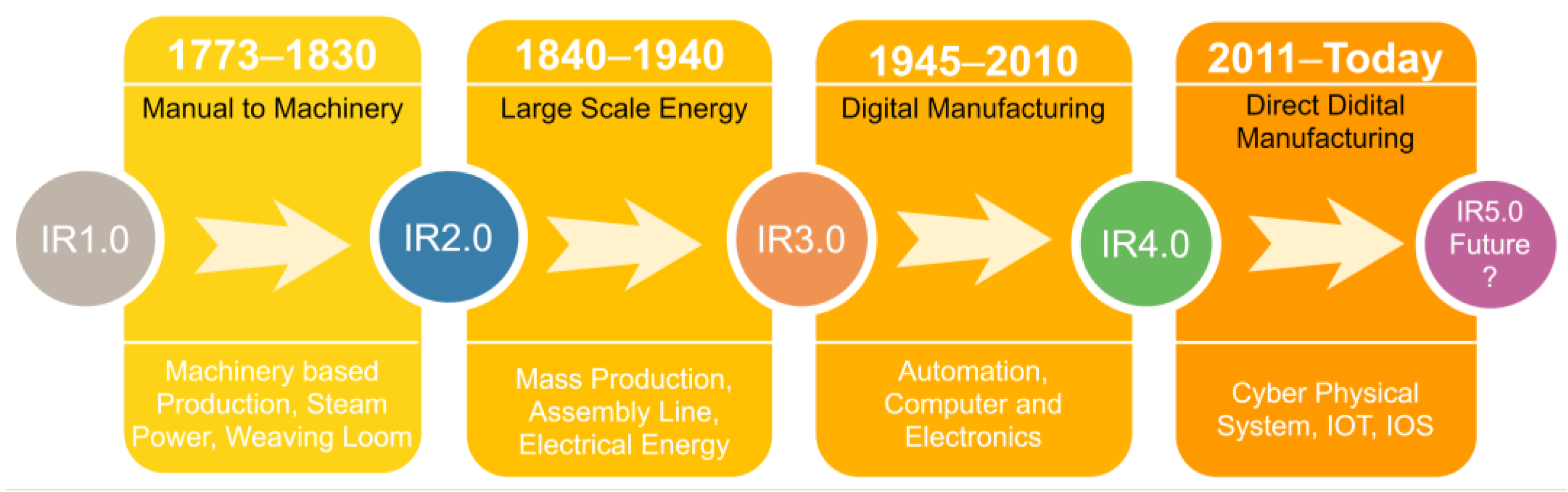
:1. Introduction
1.1. Melting Based Additive Manufacturing
1.2. Solid-State Additive Manufacturing
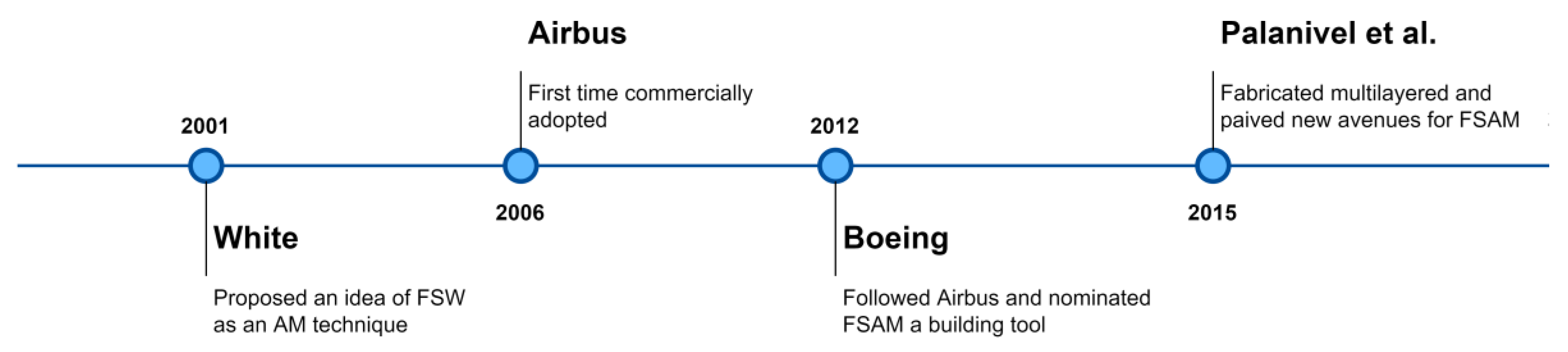
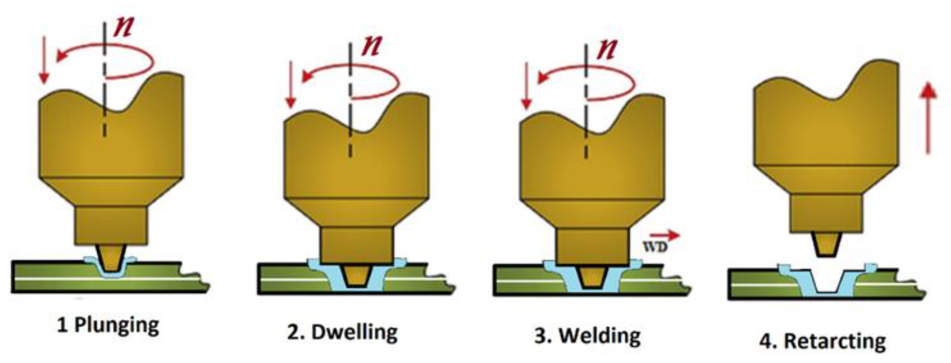
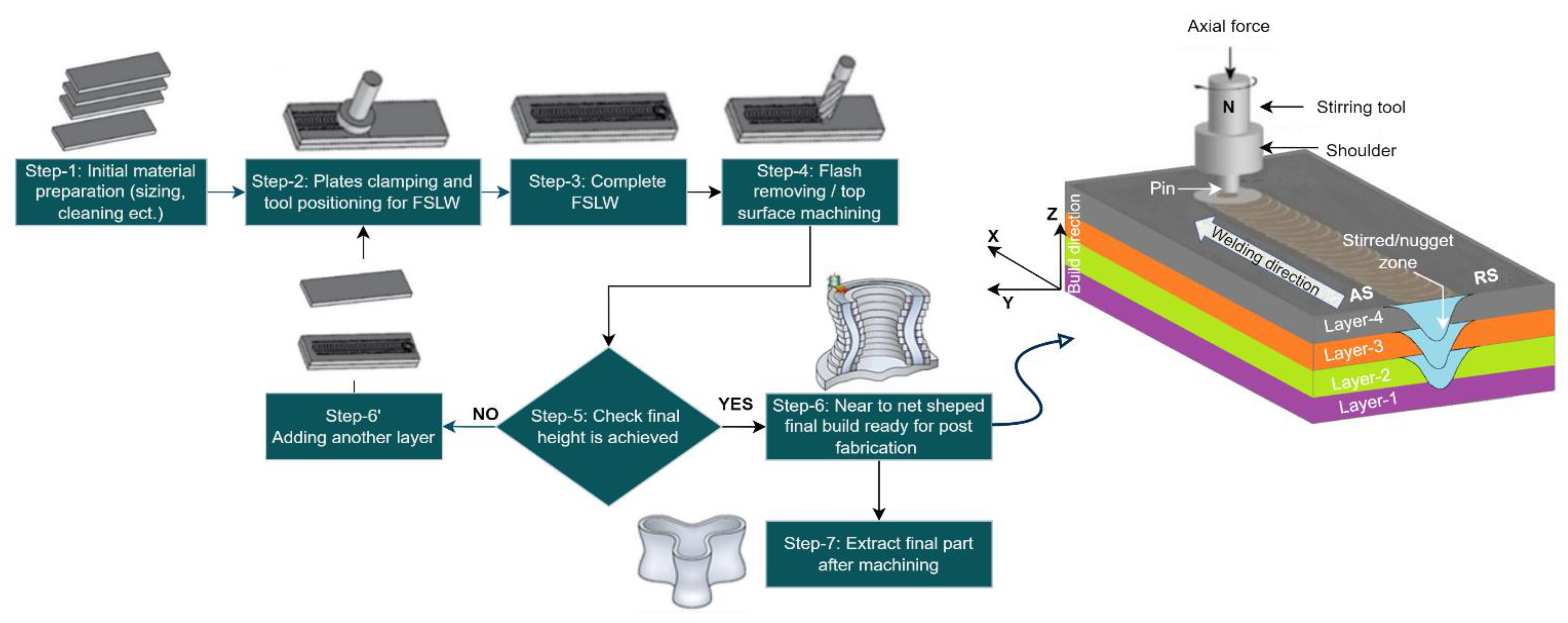
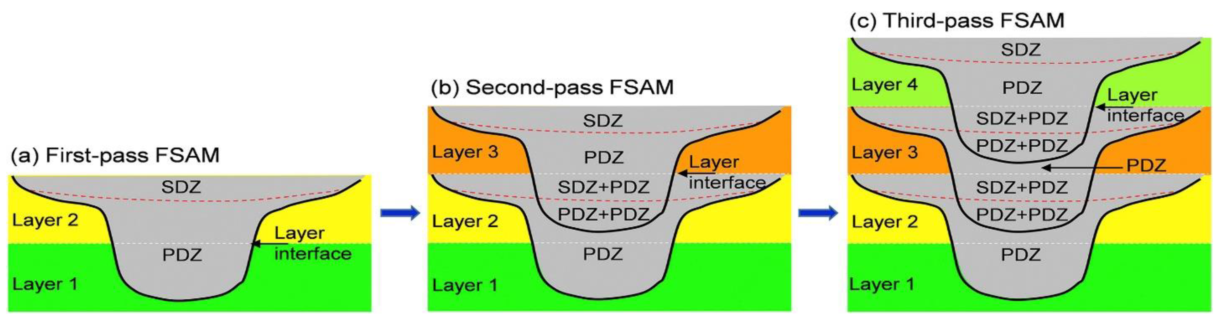
2. Friction Stir Additive Manufacturing (FSAM)
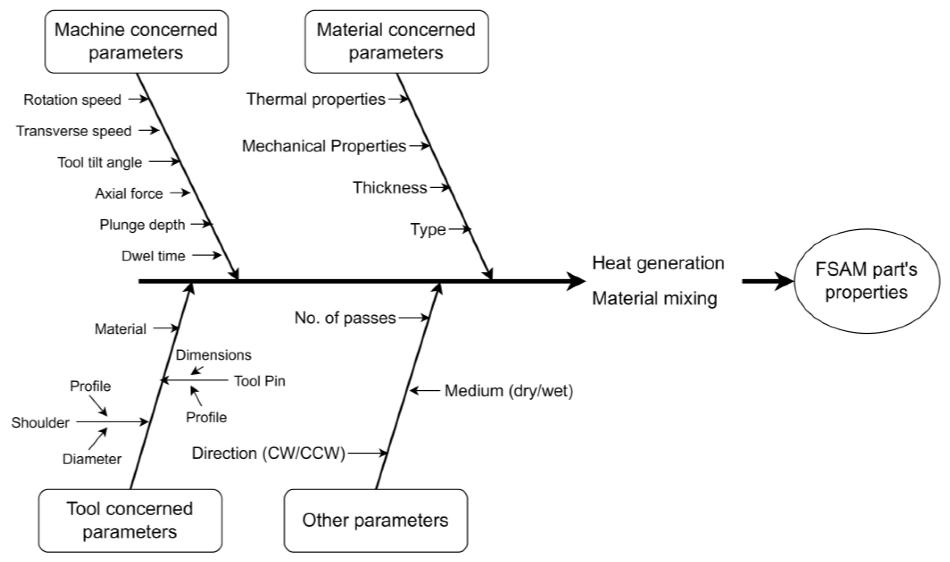
3. Parameters Affecting FSAM
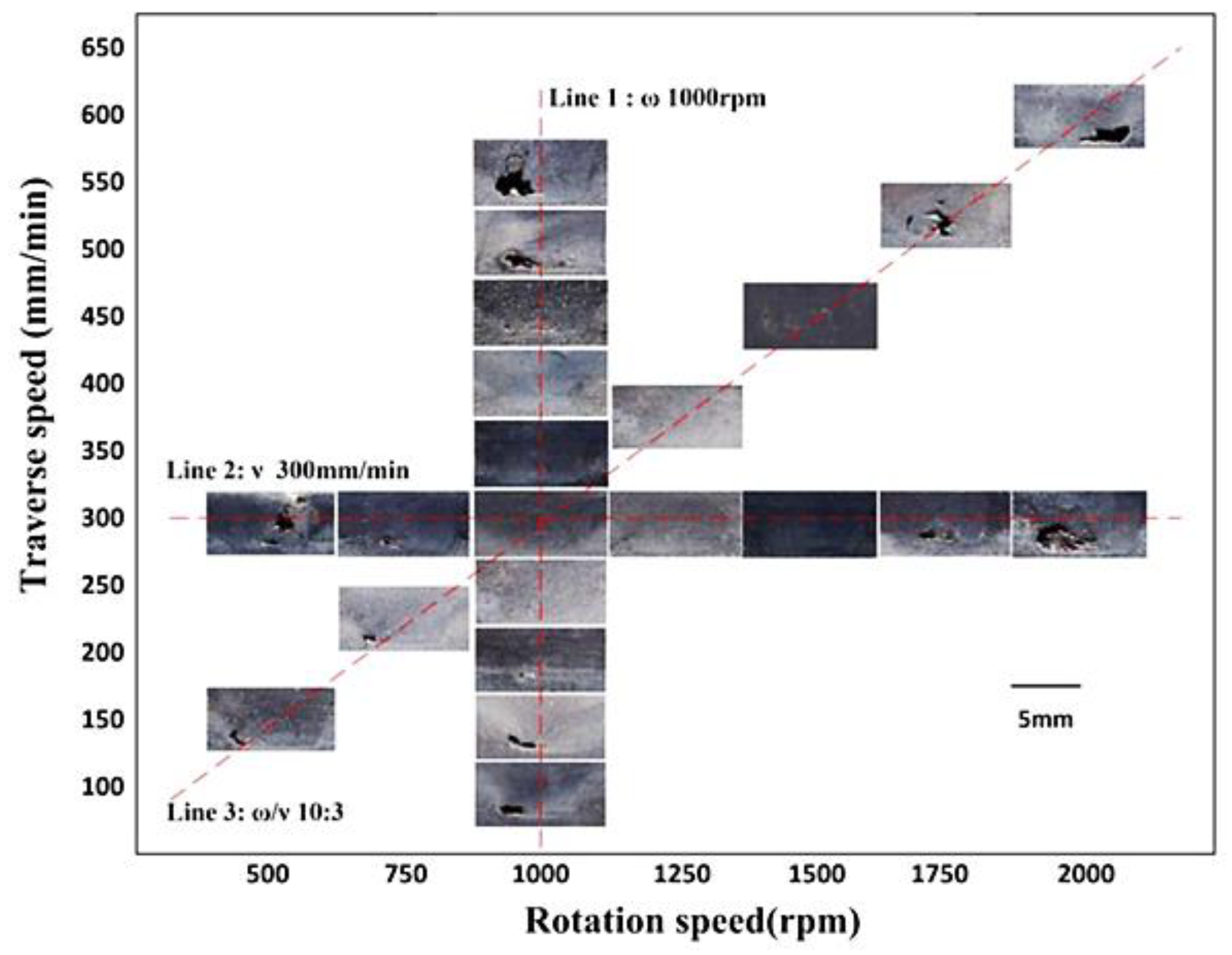
3.1. Machine Concerned Parameters
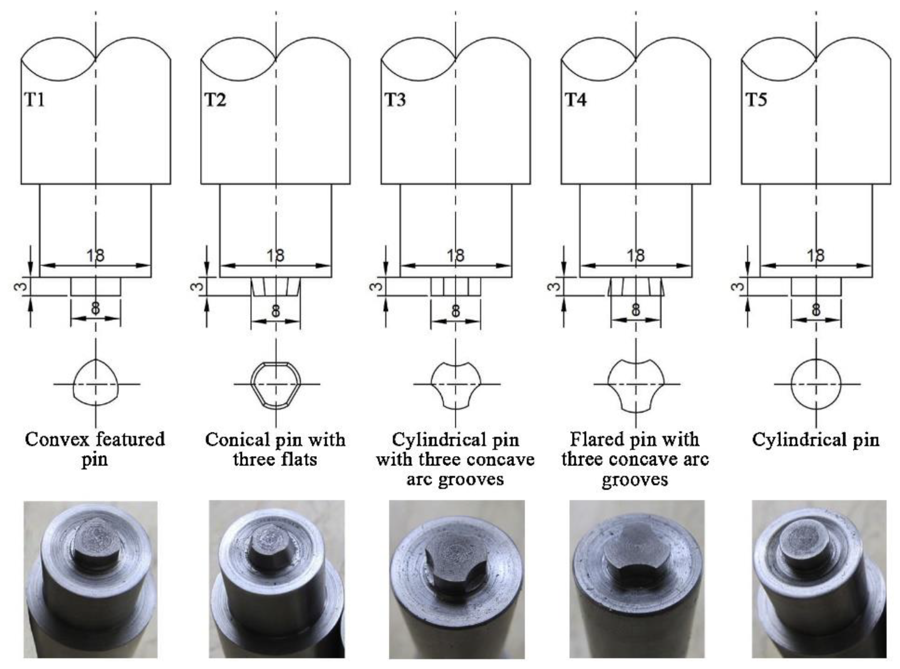
3.2. Tool Concerned Parameters
3.3. Material Concerned Parameters

| Sr. No. | Material Concerned Parameters | Machine Concerned Parameters | Ref. | |||||
|---|---|---|---|---|---|---|---|---|
| Material/No. of Layers | BH-mm | RS- rpm | TS-mmmin−1 | PD *-mm | TA-Deg. | Medium | ||
| 1 | WE43 rolled condition/4 | 5.6 | 800, 1400 | 102 | — | 1.5° | Air | [32] |
| 2 | AA5083-O solid sol. strength/4 | 11.2 | 500 | 152 | — | 1.5° | Air | [48] |
| 3 | AA 7075-O/9 | 42 | 600 | 60 | 0.2 | 2° | Air | [70] |
| 4 | 2050 cast/12, AA2050-T3/7 | 432 | 250 | 204 | — | 1 | Water spray | [71] |
| 5 | 2195-T8 Al-Li/5 | — | 800, 900, 1000 | 100 | — | — | Air | [62] |
| 6 | AA6061-T6/4, AA-6082(sub) | — | 1000 | 100 | — | — | Air | [49,69,72] |
| 7 | AA 7N01-T4/12 | 42 | 1200 | 60 | — | — | Air | [73] |
| 8 | IF, St52 steel/2 | — | 600 | 40, 70, 100 | — | 3° | Air | [74] |
| 9 | PMMA, AISI 304/4 each | — | 850 | 45 | — | 2.5° | TP ~280 °C | [75] |
| 10 | AZ31B-HA magnesium | — | 900 | 30 | — | 3° | Air | [76,77] |
| 11 | AZ31-H24 mg alloy/7 | — | 1000 | 100 | 1.65 | −0.5° | Air | [78] |
| 12 | 2195-T8 Al-Li alloy/3 | — | 700 | 200 | — | — | Air | [79] |
| 13 | A357/SiC AMMC and Al-6XXX/2 | — | 500, 1000 | 100, 200 | 1 | 3° | Air | [80] |
| 14 | Pure copper and steel/2 | 6 | 600 | 50 | 1–1.4 | 2° | Air | [81] |
| 15 | AA 6061-T651, Steel 1018/2 | — | 600, 1000 | 300,600 | — | 1° | Air | [82] |
| 16 | Al plates/4 | — | 800, 1000, 1200 | 100 | — | — | Air | [83] |
| 17 | Al-7A04-T6/4 | — | 700 | 160 | — | 2.5° | Water 20 °C | [84] |
| 18 | 7N01-T4/12 | 42 | 1200 | 80 | — | — | Air/water 25 °C | [85] |
| 19 | AA6061-T6/4 | — | 1200 | 100 | — | — | Air | [86] |
| 20 | Al–Zn–Mg–Cu sol. treated/4 | — | 700 | 160 | — | — | Water 15 °C | [87] |
| 21 | Al–Zn–Mg–Cu 7A04-T6/4 | 10.5 | 700 | 160 | — | — | Water 20 °C | [50] |
| 22 | PP and Textile SS/7 | — | 850 | 45 | — | 2.5° | TP ~180 °C | [88] |
| 23 | Pure Cu cold rolled T3 | — | 600 | 50 | 0.2 | 3° | Water | [89] |
| 24 | Al-Cu pipes AA5086 and C12200 | — | 400, 500, 600, 700 | 40, 60, 80 | 0.2 | 3° | Air | [90] |
| 25 | Al 5059-O/6 | 20 | 450 | 63 | 0.25 | 2° | Air | [91] |
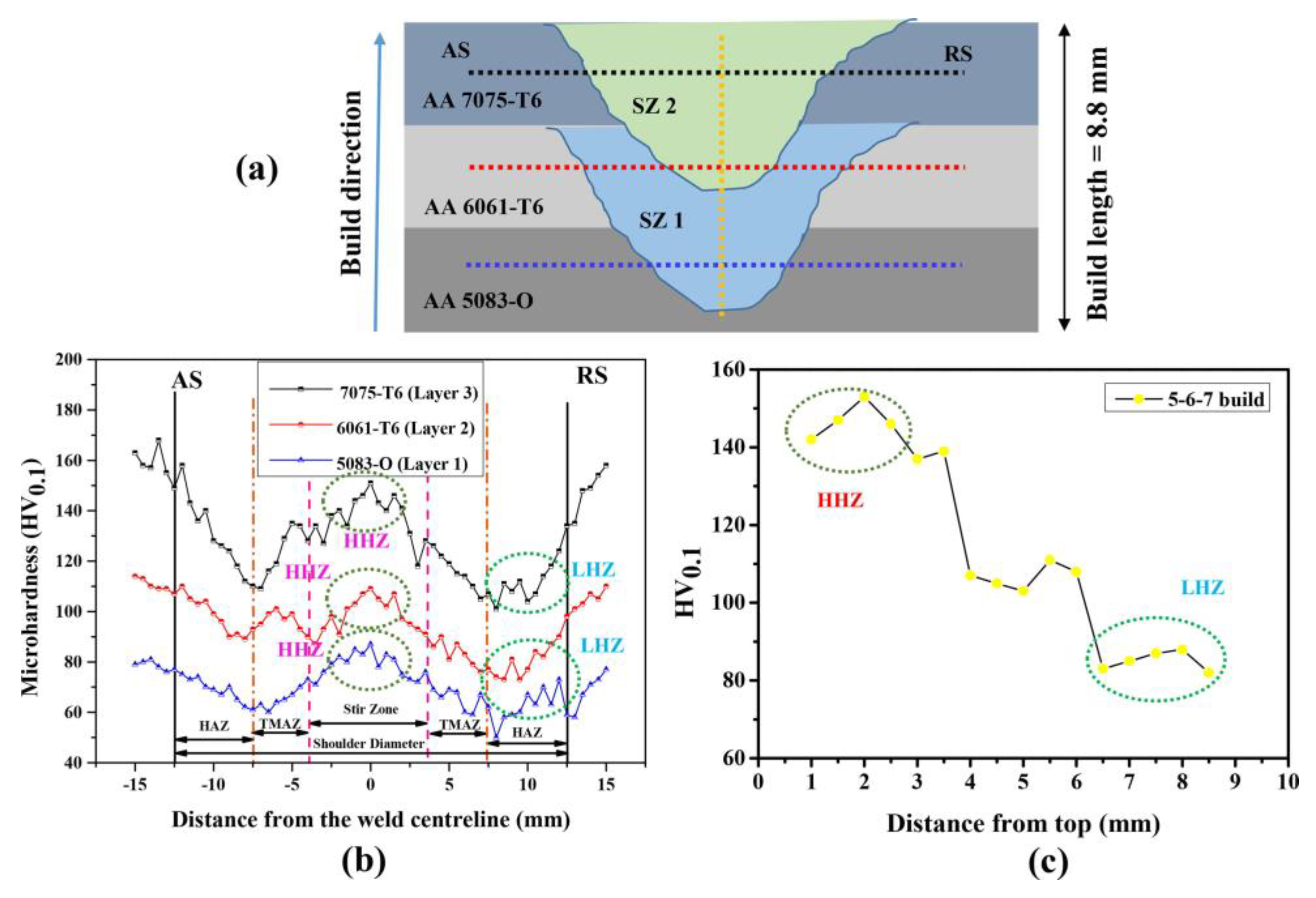
| 26 | Al-5083-O. 6061-T6, 7075-T6/3 | 8.8 | 750 | 55 | 1.7 | 3° | Air | [92] |
| 27 | Al-7075-T6/5 | — | 2000 | 65, 80, 95 | — | 0.5° | Air | [67] |
| 28 | Al-6061, Al-7075/7 | — | 1200, 1100 | 40, 50 | 1.15 | 2° | Air | [93] |
| 29 | Al-5083, Al-7075/3 | — | 850 | 55 | — | — | Air | [94] |
| 30 | Al-2060/2 | 4 | 1500–1800 | 300–500 | — | — | Air | [95] |
| 31 | Mg-AZ91, Cu, Al-7075/3 | — | 2000 | 40 | — | 0 | Air | [96] |
| Sr. No. | Tool Concerned Parameters | Ref. | |||
|---|---|---|---|---|---|
| Pin Profile/Length-mm | PD-mm d1/d2 | SD-mm | Material | ||
| 1 | Right-handed stepped spiral/2.2 | 3.5/6 | 11.8 | Tool steel | [32] |
| 2 | Triple flat left-handed stepped spiral tool/4.75 | 3.9/5.9 | 10 | — | [48] |
| 3 | Left cylindrical threaded pin/5.2 | 14/14 | 30 | GH4169 steel | [70] |
| 4 | Threaded taper with 3 flats/12.85 | 8.3/12.7 | 28.6 | — | [71] |
| 5 |
| 8/8 | 18 | — | [62] |
| 6 | Conical Pin/8 | 6/8 | 24 | H13 steel | [49,69,72] |
| 7 | Right-handed stepped spiral/5 | 5/6 | 15 | Tool steel | [73] |
| 8 | Cylindrical/0.5 | 6/6 | 20 | WC | [74] |
| 9 | Threaded corner-removed triangle with hole/6 | 6/6 | 20 | — | [75] |
| 10 | Cylindrical treaded/6 | 6/6 | 16 | Nitrated HSS | [76,77] |
| 11 | Threaded taper triangular/6.5 | 4.5/7 | 18 | H13 steel | [78] |
| 12 | — | — | — | — | [79] |
| 13 | — | — | — | — | [80] |
| 14 | Plain taper/3.1 | 3/5 | 10 | WRe | [81] |
| 15 | Cylindrical/6, 6.2 | 8/8 | 18 | H13 steel | [82] |
| 16 | — | — | — | — | [83] |
| 17 | — | — | — | — | [84] |
| 18 | Conical threaded/5 | 5/6 | 15 | — | [85] |
| 19 | Conical/7 | 6/7 | 24 | — | [86] |
| 20 | Conical threaded/4 | 5/7 | 15.5 | — | [87] |
| 21 | Conical threaded/5.5 | 4.2/7 | 15.5 | — | [50] |
| 22 | Threaded corner-removed triangle with hole/6 | 6/6 | 20 | — | [88] |
| 23 | Tapper threaded/2.1 | 4.4 | 10 | — | [89] |
| 24 | Cylindrical/2 | 3/3 | 10 | — | [90] |
| 25 | Tapper threaded/5 | 4/6 | 12 | H13 steel | [91] |
| 26 | Tapper threaded/4.7 | 3/7 | 25 | H13 steel | [92] |
| 27 | Threaded taper with 3 flats/6 | 8 | 20 | — | [67] |
| 28 | Tapper threaded/4 | 6/8 | 24 | H13 steel | [93] |
| 29 | Tapper threaded/4.7 | 4.7/7 | 25 | H13 steel | [94] |
| 30 | Conical/3 | 3/5 | 10 | — | [95] |
| 31 | Cylindrical threaded | 4 | 11.8 | HSS | [96] |
| Material | Parameters | Ref. | ||||
|---|---|---|---|---|---|---|
| Pin Profile | rpm | mm/min | Tilt Angle | Medium | ||
| AA5083-O | Triple flat left-handed stepped spiral | 500 | 152 | 1.5° | Air | [48] |
| PMMA, S304 AISI | Threaded corner-removed triangle | 850 | 45 | 2.5° | Air, TP ~280 °C | [75] |
| Mg alloy AZ31-H24 | Threaded taper triangular | 1000 | 100 | −0.5° | Air | [78] |
| A357/SiC AMMC and Al6XXX | — | 500, 1000 | 100, 200 | 3° | Air | [80] |
| Pure copper and steel | Plain tapper | 600 | 50 | 2° | Air | [81] |
| Al–Zn–Mg–Cu 7A04-T6 | — | 700 | 160 | 2.5 | water | [84] |
| 7N01-T4 | Conical threaded | 1200 | 80 | — | Air/water | [85] |
| AA6061-T6 | Plain conical | 1200 | 100 | — | Air | [86] |
| Al–Zn–Mg–Cu | Conical threaded | 700 | 160 | — | water | [87] |
| Al–Zn–Mg–Cu 7A04-T6 | Conical threaded | 700 | 160 | — | water | [50] |
| PP and Textile SS | Threaded corner-removed triangle | 850 | 45 | 2.5° | Air, TP ~280 °C | [88] |
| Pure Cu cold rolled T3 | Tapper threaded | 600 | 50 | 3° | Water | [89] |
| Al-5083, Al-7075 | Tapper threaded | 850 | 55 | — | Air | [94] |
4. Defects Elicited in FSAM
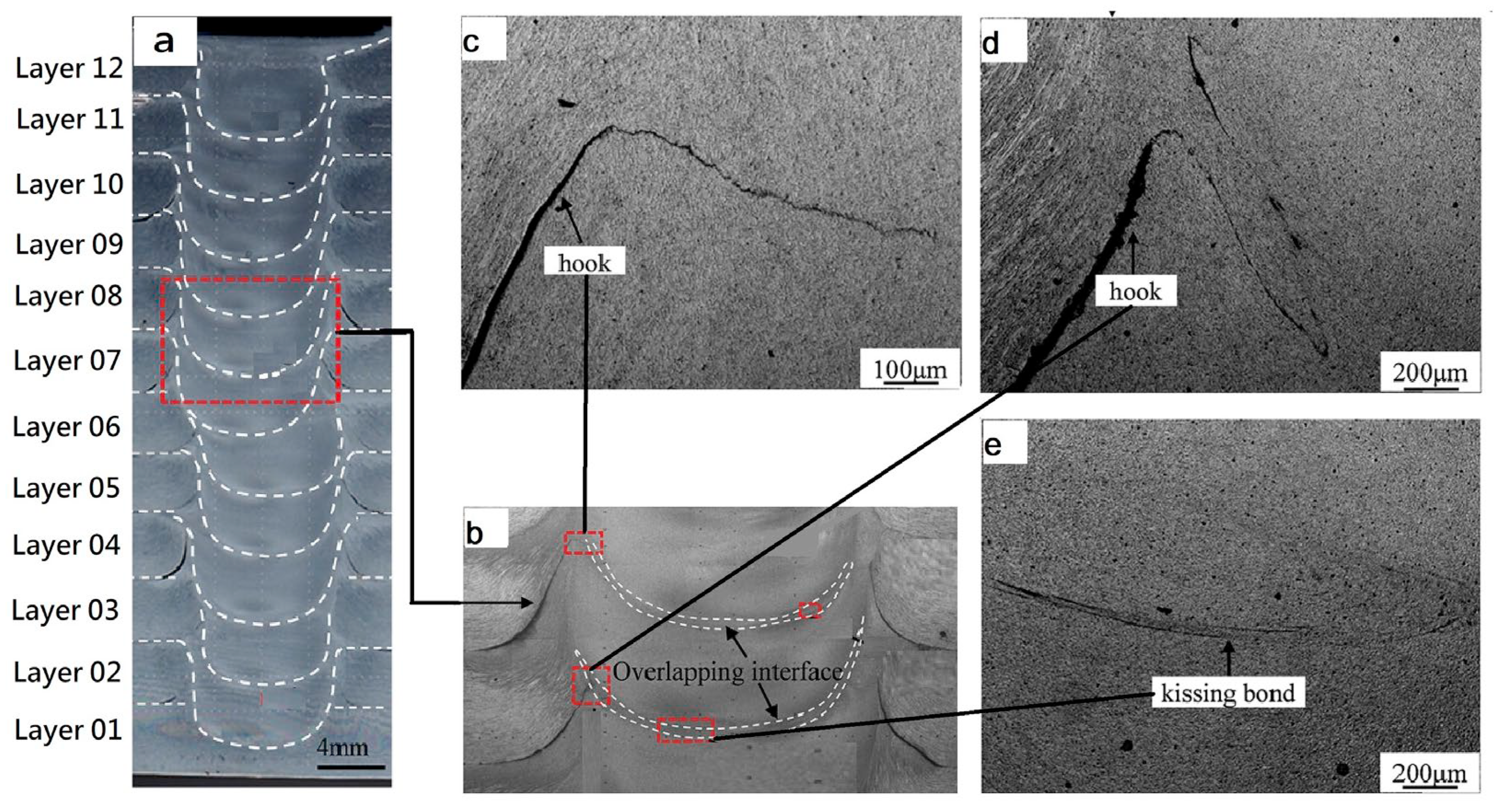
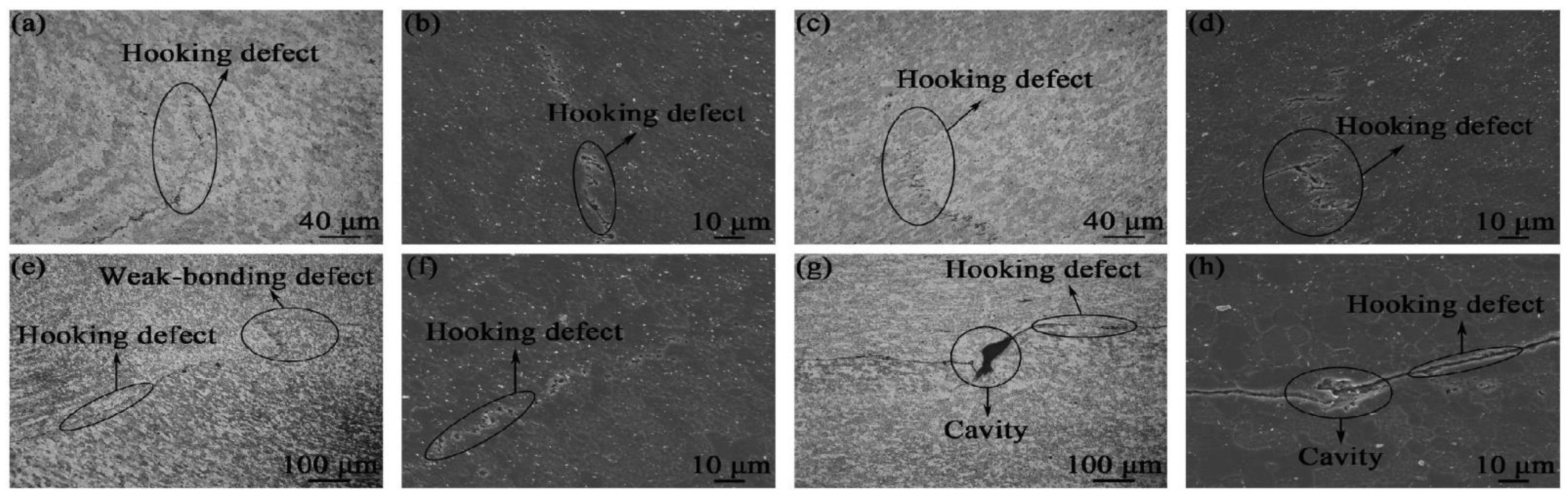
4.1. Hook and Kiss Bonding Defect
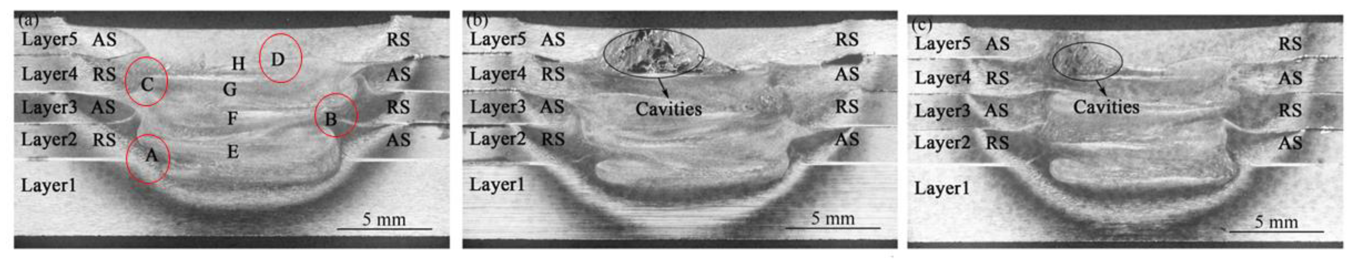
4.2. Tunnel, Micro-Voids, Pores, and Cracking Defect
5. Microstructure and Mechanical Properties of FSAM Build
5.1. Identical Material Laminates
5.1.1. Magnesium Based Alloys
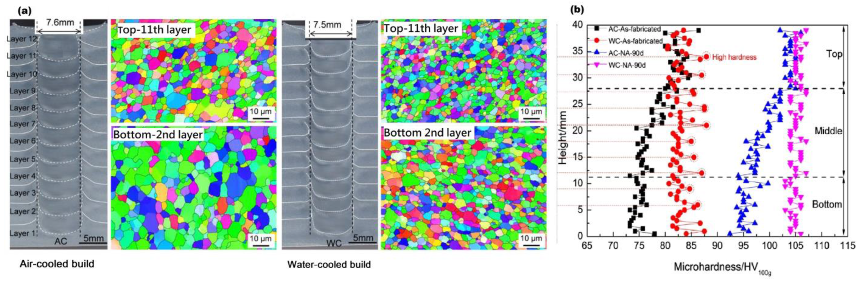
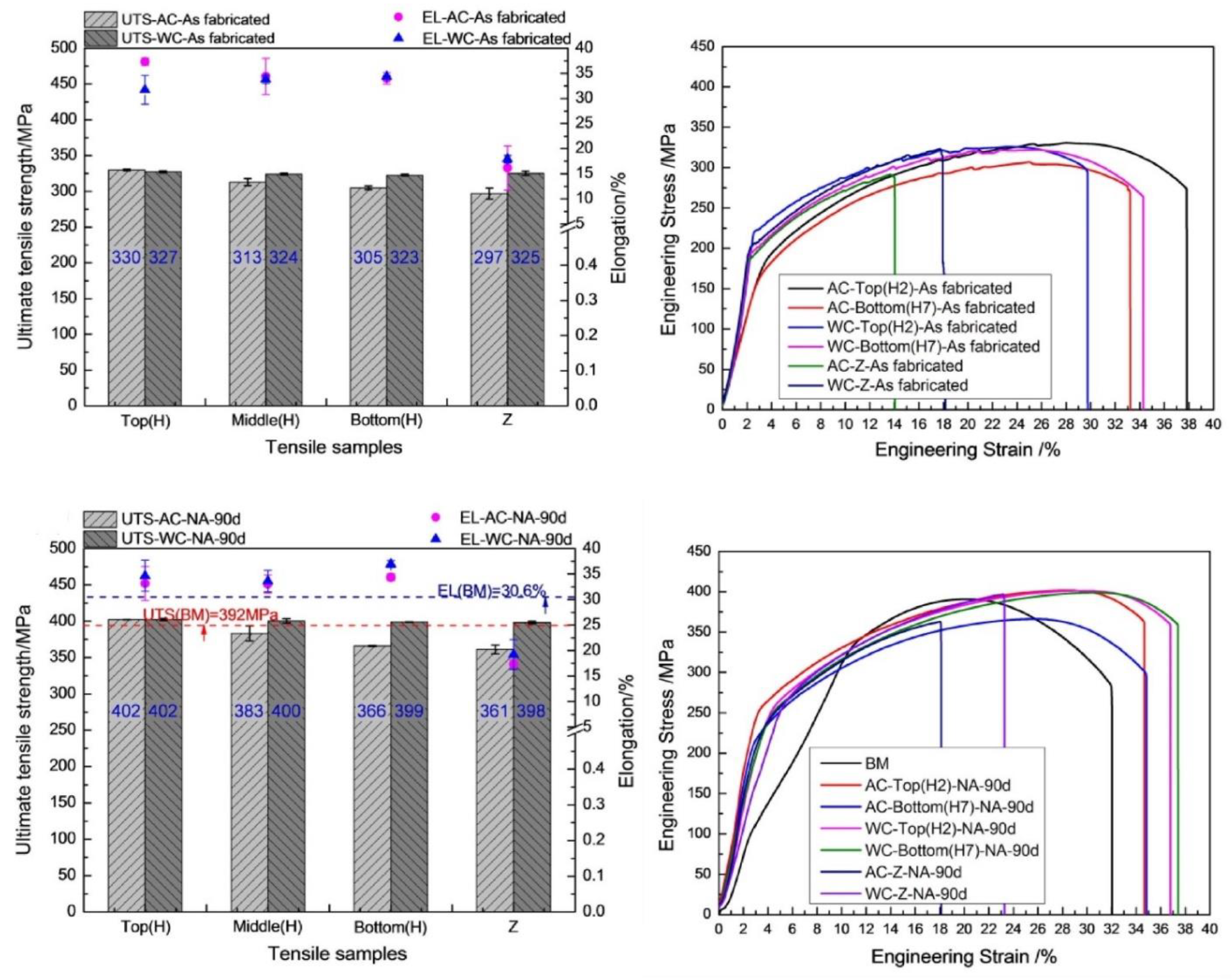
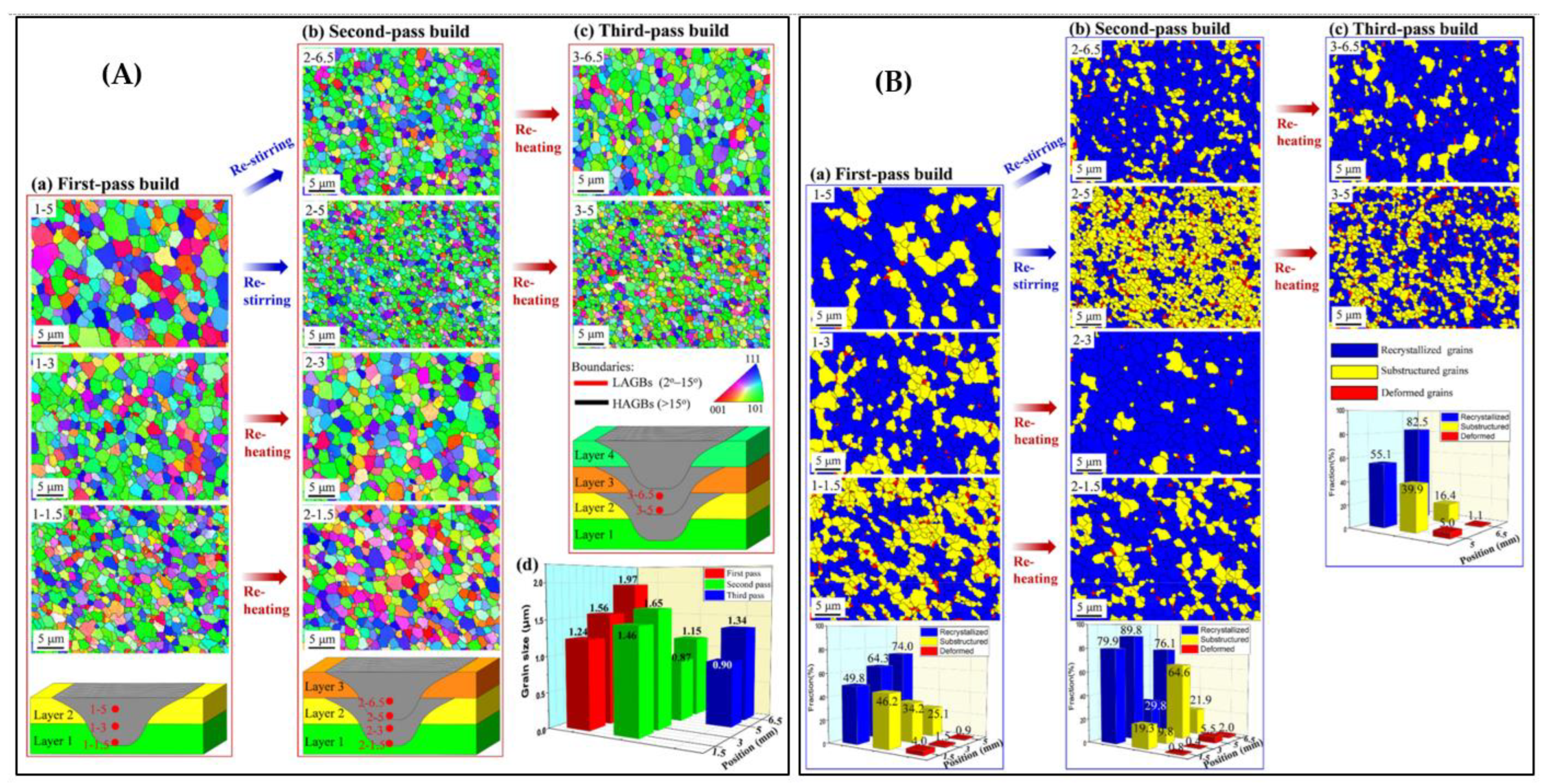
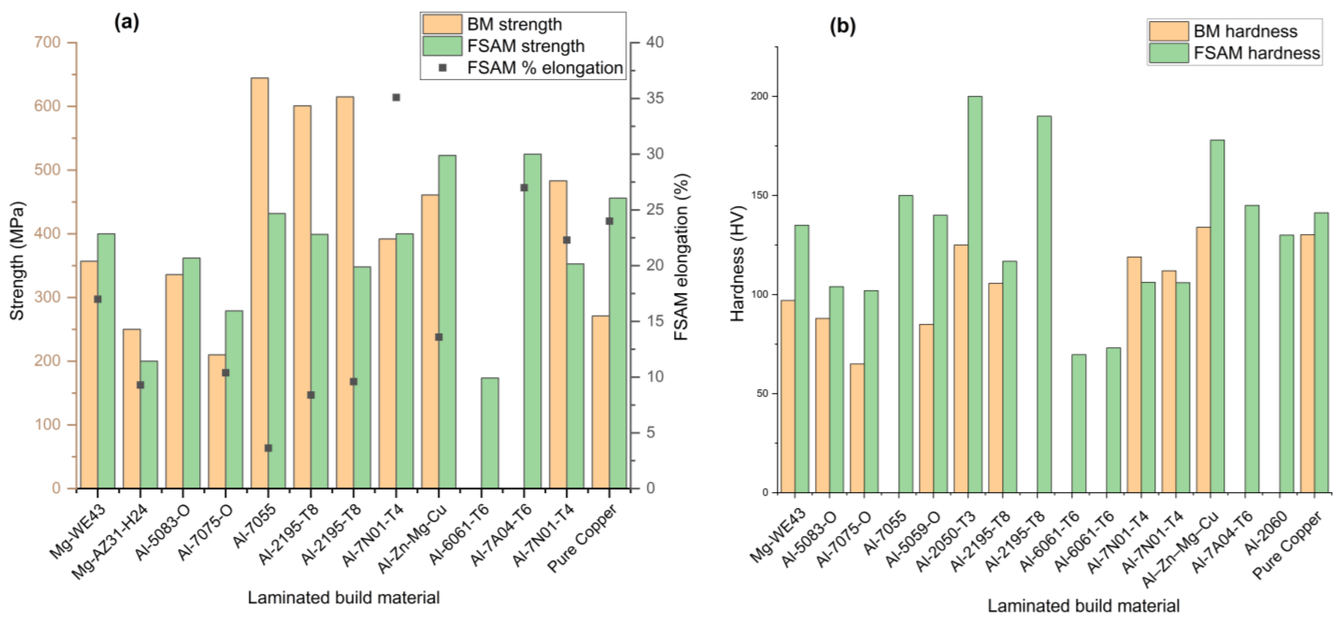
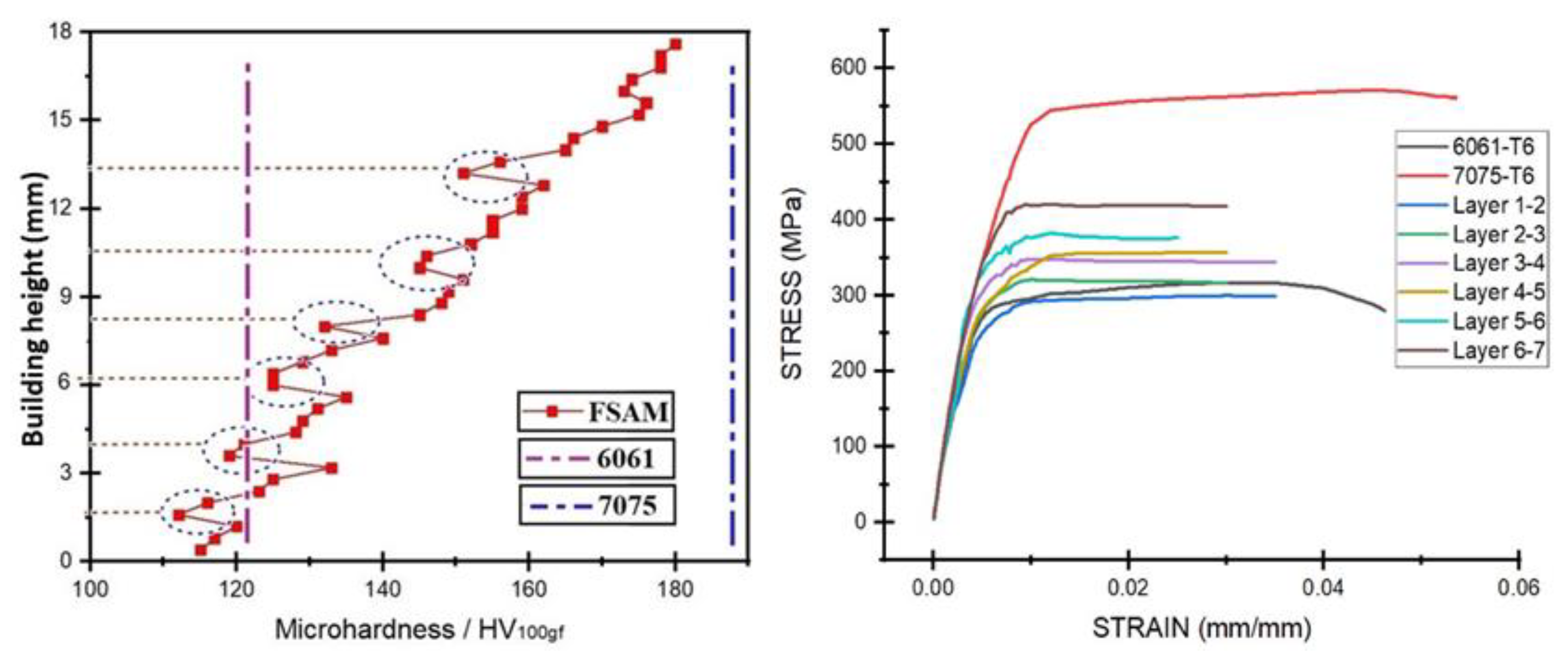
5.1.2. Aluminum Based Alloys
5.1.3. Copper Based Alloys
5.2. Multi Material Laminates
5.2.1. Fully Gradient Structure
5.2.2. Alternative Gradient Structure
5.2.3. Sandwiched Structure
6. Viability and Potential Applications of FSAM
6.1. Viability of 3D Part Fabrication
6.2. Potential Practical Application of FSAM
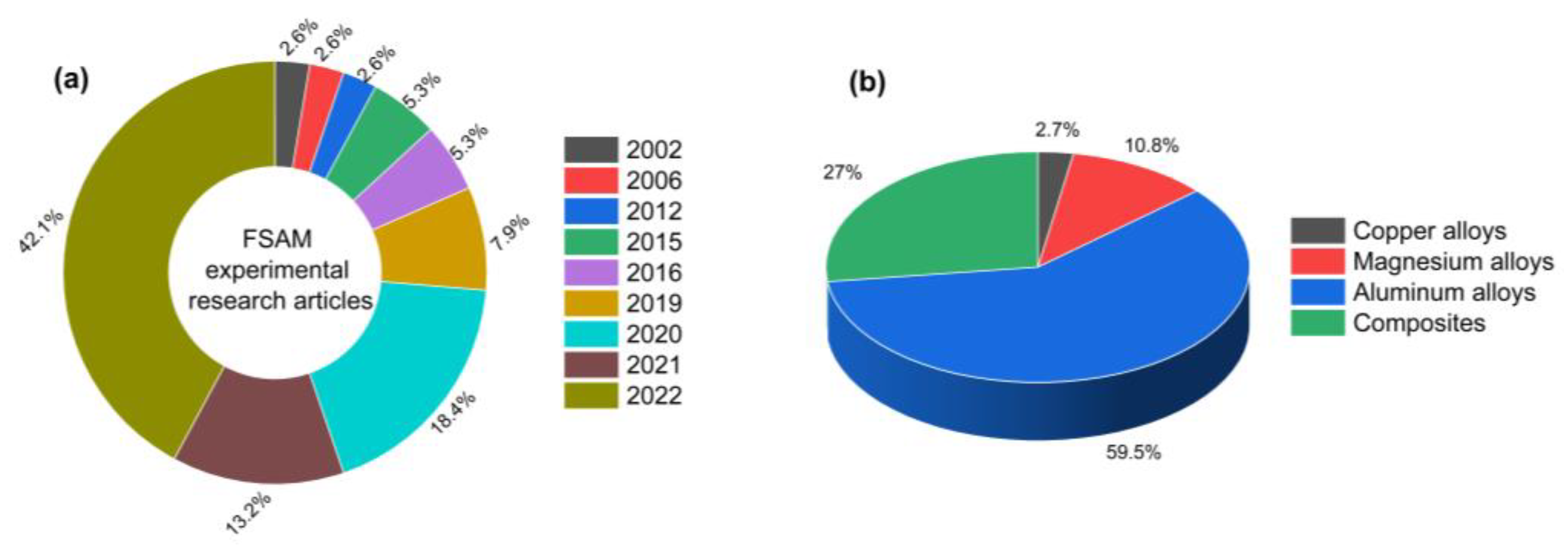
7. Current Academic Research Status of FSAM
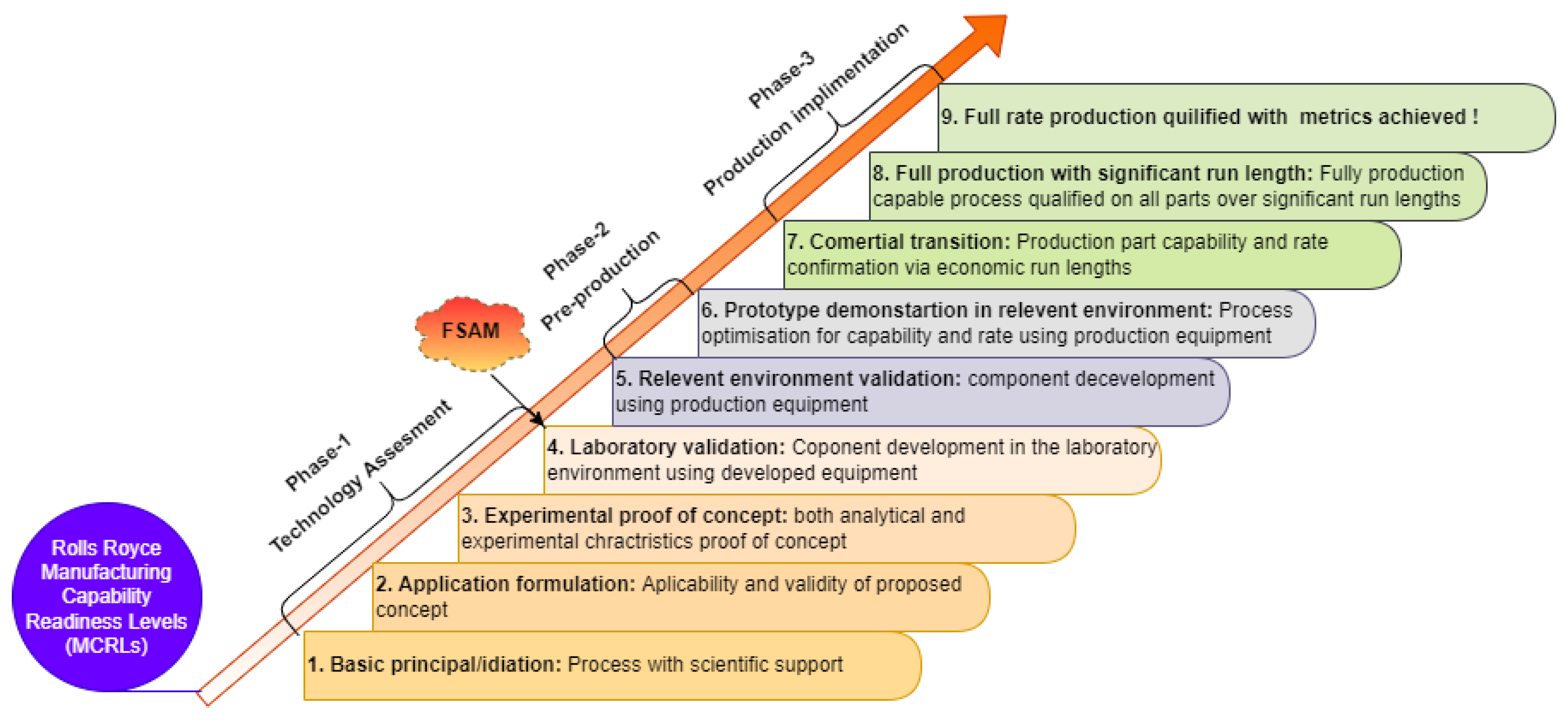
8. Current Technology Readiness Level (TRL) of FSAM
9. Conclusions and Future Recommendations
- FSAM has been successfully employed to produce defect-free parts with excellent homogeneous mechanical properties, equiaxed refined grain structure, and rapid production rate, thereby addressing the shortcomings of existing melting-based additive manufacturing processes.
- FSAM can also be used to produce bulk material with ultrafine grain structure (less than 0.5 µm).
- Multi-material or new alloys parts with simple geometry can be easily fabricated using FSAM, and parts with a low level of complexity can also be achieved after post processing machining.
- FSAM has gained a lot of attention in the research community in recent years, and it is now at laboratory validation phase (TRL-4) and will soon be used in mainstream additive manufacturing processes.
- The primary challenge of this game-changing process is to eliminate defects by controlling process parameters, and most studies used basic parameters such as rotation speed, transverse speed, and tilt angle. More process parameters, however, must be explored and investigated in order to obtain a sound microstructure and mechanical properties.
- Although mechanical properties such as micro-hardness and tensile strength are extensively studied for various material additive laminates, failure properties under cyclic loading are rare and should be investigated.
- Among non-ferrous alloys, only a few aluminum aerospace alloys (~60%) have been studied in the context of FSAM to date, followed by magnesium-based alloys (~11%). However, other harder alloys such as titanium and nickel alloys need to be further explored in the future in the context of this novel technique.
Author Contributions
Funding
Institutional Review Board Statement
Informed Consent Statement
Data Availability Statement
Acknowledgments
Conflicts of Interest
References
- Crafts, N.F.R.; Harley, C.K. Output growth and the British industrial revolution: A restatement of the Crafts-Harley view. Econ. Hist. Rev. 1992, 45, 703–730. [Google Scholar] [CrossRef]
- Holmström, J.; Holweg, M.; Khajavi, S.H.; Partanen, J. The direct digital manufacturing (r) evolution: Definition of a research agenda. Oper. Manag. Res. 2016, 9, 1–10. [Google Scholar] [CrossRef]
- Abdullah, Q.; Humaidi, N.; Shahrom, M. Industry revolution 4.0: The readiness of graduates of higher education institutions for fulfilling job demands. Rom. J. Inf. Technol. Autom. Control 2020, 30, 15–26. [Google Scholar] [CrossRef]
- Pereira, A.C.; Romero, F. A review of the meanings and the implications of the Industry 4.0 concept. Procedia Manuf. 2017, 13, 1206–1214. [Google Scholar] [CrossRef]
- Kazancoglu, Y.; Ozkan-Ozen, Y.D. Analyzing Workforce 4.0 in the Fourth Industrial Revolution and proposing a road map from operations management perspective with fuzzy DEMATEL. J. Enterp. Inf. Manag. 2018, 31, 891–907. [Google Scholar] [CrossRef]
- ISO/ASTM52900; Additive Manufacturing—General Principles Terminology. Rapid Manufacturing Association. ISO: Geneva, Switzerland, 2013. [CrossRef]
- Harun, W.S.W.; Kamariah, M.S.I.N.; Muhamad, N.; Ghani, S.A.C.; Ahmad, F.; Mohamed, Z. A review of powder additive manufacturing processes for metallic biomaterials. Powder Technol. 2018, 327, 128–151. [Google Scholar] [CrossRef]
- Anderson, I.E.; White, E.M.H.; Dehoff, R. Feedstock powder processing research needs for additive manufacturing development. Curr. Opin. Solid State Mater. Sci. 2018, 22, 8–15. [Google Scholar] [CrossRef]
- Lee, P.-H.; Chung, H.; Lee, S.W.; Yoo, J.; Ko, J. Dimensional accuracy in additive manufacturing processes. In Proceedings of the International Manufacturing Science and Engineering Conference, Detroit, MI, USA, 9–13 June 2014; Volume 45806, p. V001T04A045. [Google Scholar] [CrossRef]
- Huang, S.H.; Liu, P.; Mokasdar, A.; Hou, L. Additive manufacturing and its societal impact: A literature review. Int. J. Adv. Manuf. Technol. 2013, 67, 1191–1203. [Google Scholar] [CrossRef]
- Srivastava, A.K.; Kumar, N.; Dixit, A.R. Friction stir additive manufacturing–An innovative tool to enhance mechanical and microstructural properties. Mater. Sci. Eng. B 2021, 263, 114832. [Google Scholar] [CrossRef]
- Mishra, R.S.; Haridas, R.S.; Agrawal, P. Friction stir-based additive manufacturing. Sci. Technol. Weld. Join. 2022, 27, 141–165. [Google Scholar] [CrossRef]
- Li, M.; Du, W.; Elwany, A.; Pei, Z.; Ma, C. Metal binder jetting additive manufacturing: A literature review. J. Manuf. Sci. Eng. Trans. ASME 2020, 142, 090801. [Google Scholar] [CrossRef]
- Thompson, S.M.; Bian, L.; Shamsaei, N.; Yadollahi, A. An overview of Direct Laser Deposition for additive manufacturing; Part I: Transport phenomena, modeling and diagnostics. Addit. Manuf. 2015, 8, 36–62. [Google Scholar] [CrossRef]
- Liu, R.; Wang, Z.; Sparks, T.; Liou, F.; Newkirk, J. Aerospace applications of laser additive manufacturing. In Laser Additive Manufacturing; Elsevier: Amsterdam, The Netherlands, 2017; pp. 351–371. [Google Scholar]
- Nandwana, P.; Elliott, A.M.; Siddel, D.; Merriman, A.; Peter, W.H.; Babu, S.S. Powder bed binder jet 3D printing of Inconel 718: Densification, microstructural evolution and challenges. Curr. Opin. Solid State Mater. Sci. 2017, 21, 207–218. [Google Scholar] [CrossRef]
- Gonzalez-Gutierrez, J.; Cano, S.; Schuschnigg, S.; Kukla, C.; Sapkota, J.; Holzer, C. Additive manufacturing of metallic and ceramic components by the material extrusion of highly-filled polymers: A review and future perspectives. Materials 2018, 11, 840. [Google Scholar] [CrossRef] [Green Version]
- Gao, W.; Zhang, Y.; Ramanujan, D.; Ramani, K.; Chen, Y.; Williams, C.B.; Wang, C.C.L.; Shin, Y.C.; Zhang, S.; Zavattieri, P.D. The status, challenges, and future of additive manufacturing in engineering. Comput. Des. 2015, 69, 65–89. [Google Scholar] [CrossRef]
- Gülcan, O.; Günaydın, K.; Tamer, A. The state of the art of material jetting—A critical review. Polymers 2021, 13, 2829. [Google Scholar] [CrossRef]
- Mirzaali, M.J.; Edens, M.E.; de la Nava, A.H.; Janbaz, S.; Vena, P.; Doubrovski, E.L.; Zadpoor, A.A. Length-Scale Dependency of Biomimetic Hard-Soft Composites; Nature Publishing Group: Berlin, Germany, 2018; Volume 8. [Google Scholar]
- Malekipour, E.; El-Mounayri, H. Common defects and contributing parameters in powder bed fusion AM process and their classification for online monitoring and control: A review. Int. J. Adv. Manuf. Technol. 2018, 95, 527–550. [Google Scholar] [CrossRef]
- Dowling, L.; Kennedy, J.; O’Shaughnessy, S.; Trimble, D. A review of critical repeatability and reproducibility issues in powder bed fusion. Mater. Des. 2020, 186, 108346. [Google Scholar] [CrossRef]
- Gisario, A.; Kazarian, M.; Martina, F.; Mehrpouya, M. Metal additive manufacturing in the commercial aviation industry: A review. J. Manuf. Syst. 2019, 53, 124–149. [Google Scholar] [CrossRef]
- Gibson, I.; Rosen, D.; Stucker, B.; Khorasani, M. Sheet lamination. In Additive Manufacturing Technologies; Springer: Berlin/Heidelberg, Germany, 2021; pp. 253–283. ISBN 978-3-030-56126-0. [Google Scholar]
- Bagheri, A.; Jin, J. Photopolymerization in 3D printing. ACS Appl. Polym. Mater. 2019, 1, 593–611. [Google Scholar] [CrossRef] [Green Version]
- Revilla-León, M.; Sánchez-Rubio, J.L.; Besné-Torre, A.; Özcan, M. A report on a diagnostic digital workflow for esthetic dental rehabilitation using additive manufacturing technologies. Int. J. Esthet. Dent. 2018, 13, 184–196. [Google Scholar] [PubMed]
- Agrawal, P.; Thapliyal, S.; Nene, S.S.; Mishra, R.S.; McWilliams, B.A.; Cho, K.C. Excellent strength-ductility synergy in metastable high entropy alloy by laser powder bed additive manufacturing. Addit. Manuf. 2020, 32, 101098. [Google Scholar] [CrossRef]
- Raghavan, N.; Dehoff, R.; Pannala, S.; Simunovic, S.; Kirka, M.; Turner, J.; Carlson, N.; Babu, S.S. Numerical modeling of heat-transfer and the influence of process parameters on tailoring the grain morphology of IN718 in electron beam additive manufacturing. Acta Mater. 2016, 112, 303–314. [Google Scholar] [CrossRef] [Green Version]
- Vilaro, T.; Colin, C.; Bartout, J.-D.; Nazé, L.; Sennour, M. Microstructural and mechanical approaches of the selective laser melting process applied to a nickel-base superalloy. Mater. Sci. Eng. A 2012, 534, 446–451. [Google Scholar] [CrossRef]
- Gao, H.; Li, H. Friction additive manufacturing technology: A state-of-the-art survey. Adv. Mech. Eng. 2021, 13, 16878140211034431. [Google Scholar] [CrossRef]
- Zhang, D.; Prasad, A.; Bermingham, M.J.; Todaro, C.J.; Benoit, M.J.; Patel, M.N.; Qiu, D.; StJohn, D.H.; Qian, M.; Easton, M.A. Grain Refinement of Alloys in Fusion-Based Additive Manufacturing Processes. Metall. Mater. Trans. A Phys. Metall. Mater. Sci. 2020, 51, 4341–4359. [Google Scholar] [CrossRef]
- Palanivel, S.; Nelaturu, P.; Glass, B.; Mishra, R.S. Friction stir additive manufacturing for high structural performance through microstructural control in an Mg based WE43 alloy. Mater. Des. 2015, 65, 934–952. [Google Scholar] [CrossRef]
- Srivastava, M.; Rathee, S.; Maheshwari, S.; Noor Siddiquee, A.; Kundra, T.K. A review on recent progress in solid state friction based metal additive manufacturing: Friction stir additive techniques. Crit. Rev. Solid State Mater. Sci. 2019, 44, 345–377. [Google Scholar] [CrossRef]
- Sun, S.-H.; Koizumi, Y.; Kurosu, S.; Li, Y.-P.; Chiba, A. Phase and grain size inhomogeneity and their influences on creep behavior of Co–Cr–Mo alloy additive manufactured by electron beam melting. Acta Mater. 2015, 86, 305–318. [Google Scholar] [CrossRef]
- Panchagnula, J.S.; Simhambhatla, S. Additive manufacturing of complex shapes through weld-deposition and feature based slicing. In Proceedings of the ASME International Mechanical Engineering Congress and Exposition, Houston, TX, USA, 13–19 November 2015; Volume 57359, p. V02AT02A004. [Google Scholar] [CrossRef]
- Paoletti, I. Mass customization with additive manufacturing: New perspectives for multi performative building components in architecture. Procedia Eng. 2017, 180, 1150–1159. [Google Scholar] [CrossRef]
- du Plessis, A.; le Roux, S.G.; Booysen, G.; Els, J. Directionality of cavities and porosity formation in powder-bed laser additive manufacturing of metal components investigated using X-ray tomography. 3D Print. Addit. Manuf. 2016, 3, 48–55. [Google Scholar] [CrossRef] [Green Version]
- Spoerk, M.; Sapkota, J.; Weingrill, G.; Fischinger, T.; Arbeiter, F.; Holzer, C. Shrinkage and warpage optimization of expanded-perlite-filled polypropylene composites in extrusion-based additive manufacturing. Macromol. Mater. Eng. 2017, 302, 1700143. [Google Scholar] [CrossRef]
- Gong, H.; Rafi, K.; Gu, H.; Starr, T.; Stucker, B. Analysis of defect generation in Ti–6Al–4V parts made using powder bed fusion additive manufacturing processes. Addit. Manuf. 2014, 1, 87–98. [Google Scholar] [CrossRef]
- Everton, S.K.; Hirsch, M.; Stravroulakis, P.; Leach, R.K.; Clare, A.T. Review of in-situ process monitoring and in-situ metrology for metal additive manufacturing. Mater. Des. 2016, 95, 431–445. [Google Scholar] [CrossRef]
- Yin, S.; Cavaliere, P.; Aldwell, B.; Jenkins, R.; Liao, H.; Li, W.; Lupoi, R. Cold spray additive manufacturing and repair: Fundamentals and applications. Addit. Manuf. 2018, 21, 628–650. [Google Scholar] [CrossRef]
- Rathee, S.; Srivastava, M.; Pandey, P.M.; Mahawar, A.; Shukla, S. Metal additive manufacturing using friction stir engineering: A review on microstructural evolution, tooling and design strategies. CIRP J. Manuf. Sci. Technol. 2021, 35, 560–588. [Google Scholar] [CrossRef]
- White, D. Object Consolidation Employing Friction Joining. U.S. Patent 6,457,629 B1, 1 October 2002. [Google Scholar]
- Palanivel, S.; Mishra, R.S. Building without melting: A short review of friction-based additive manufacturing techniques. Int. J. Addit. Subtractive Mater. Manuf. 2017, 1, 82–103. [Google Scholar] [CrossRef]
- Lequeu, P.; Muzzolini, R.; Ehrstrom, J.C.; Bron, F.; Maziarz, R. High-Performance friction stir welded structures using advanced alloys. In Proceedings of the Aeromat Conference, Seattle, WA, USA, 15–18 May 2006. [Google Scholar]
- Dilip, J.J.S.; Janaki Ram, G.D.; Stucker, B.E. Additive manufacturing with friction welding and friction deposition processes. Int. J. Rapid Manuf. 2012, 3, 56–69. [Google Scholar] [CrossRef]
- Baumann, J.A. Production of Energy Efficient Preform Structures (PEEPS); The Boeing Company: Arlington, VA, USA, 2012. [Google Scholar] [CrossRef] [Green Version]
- Palanivel, S.; Sidhar, H.; Mishra, R.S. Friction Stir Additive Manufacturing: Route to High Structural Performance. JOM 2015, 67, 616–621. [Google Scholar] [CrossRef]
- Zhang, Z.; Tan, Z.J.; Li, J.Y.; Zu, Y.F.; Liu, W.W.; Sha, J.J. Experimental and numerical studies of re-stirring and re-heating effects on mechanical properties in friction stir additive manufacturing. Int. J. Adv. Manuf. Technol. 2019, 104, 767–784. [Google Scholar] [CrossRef]
- Li, Y.; He, C.; Wei, J.; Zhang, Z.; Qin, G.; Zhao, X. Correlation of local microstructures and mechanical properties of Al–Zn–Mg–Cu alloy build fabricated via underwater friction stir additive manufacturing. Mater. Sci. Eng. A 2021, 805, 140590. [Google Scholar] [CrossRef]
- Padhy, G.K.; Wu, C.S.; Gao, S. Friction stir based welding and processing technologies—Processes, parameters, microstructures and applications: A review. J. Mater. Sci. Technol. 2018, 34, 1–38. [Google Scholar] [CrossRef]
- Rivera, O.G.; Allison, P.G.; Jordon, J.B.; Rodriguez, O.L.; Brewer, L.N.; McClelland, Z.; Whittington, W.R.; Francis, D.; Su, J.; Martens, R.L.; et al. Microstructures and mechanical behavior of Inconel 625 fabricated by solid-state additive manufacturing. Mater. Sci. Eng. A 2017, 694, 1–9. [Google Scholar] [CrossRef]
- Khodabakhshi, F.; Gerlich, A.P. Potentials and strategies of solid-state additive friction-stir manufacturing technology: A critical review. J. Manuf. Process. 2018, 36, 77–92. [Google Scholar] [CrossRef]
- DebRoy, T.; Wei, H.L.; Zuback, J.S.; Mukherjee, T.; Elmer, J.W.; Milewski, J.O.; Beese, A.M.; Wilson-Heid, A.D.; De, A.; Zhang, W. Additive manufacturing of metallic components–process, structure and properties. Prog. Mater. Sci. 2018, 92, 112–224. [Google Scholar] [CrossRef]
- Frazier, W.E. Metal additive manufacturing: A review. J. Mater. Eng. Perform. 2014, 23, 1917–1928. [Google Scholar] [CrossRef]
- Slotwinski, J.A.; Garboczi, E.J.; Stutzman, P.E.; Ferraris, C.F.; Watson, S.S.; Peltz, M.A. Characterization of metal powders used for additive manufacturing. J. Res. Natl. Inst. Stand. Technol. 2014, 119, 460. [Google Scholar] [CrossRef]
- Edgar, J.; Tint, S. Additive Manufacturing Technologies: 3D Printing, Rapid Prototyping, and Direct Digital Manufacturing; Johnson Matthey: London, UK, 2015; Volume 59. [Google Scholar]
- Phillips, B.J.; Avery, D.Z.; Liu, T.; Rodriguez, O.L.; Mason, C.J.T.; Jordon, J.B.; Brewer, L.N.; Allison, P.G. Microstructure-deformation relationship of additive friction stir-deposition Al–Mg–Si. Materialia 2019, 7, 100387. [Google Scholar] [CrossRef]
- Zhang, Z.; Zhang, H.W. Numerical studies on the effect of transverse speed in friction stir welding. Mater. Des. 2009, 30, 900–907. [Google Scholar] [CrossRef]
- Zhang, Z.; Zhang, H.W. Numerical studies on controlling of process parameters in friction stir welding. J. Mater. Process. Technol. 2009, 209, 241–270. [Google Scholar] [CrossRef]
- Zhai, M.; Wu, C.S.; Su, H. Influence of tool tilt angle on heat transfer and material flow in friction stir welding. J. Manuf. Process. 2020, 59, 98–112. [Google Scholar] [CrossRef]
- Zhao, Z.; Yang, X.; Li, S.; Li, D. Interfacial bonding features of friction stir additive manufactured build for 2195-T8 aluminum-lithium alloy. J. Manuf. Process. 2019, 38, 396–410. [Google Scholar] [CrossRef]
- Zou, S.; Ma, S.; Liu, C.; Chen, C.; Ma, L.; Lu, J.; Guo, J. Multi-track friction stir lap welding of 2024 aluminum alloy: Processing, microstructure and mechanical properties. Metals 2017, 7, 1. [Google Scholar] [CrossRef] [Green Version]
- Schmidt, H.; Hattel, J.; Wert, J. An analytical model for the heat generation in friction stir welding. Model. Simul. Mater. Sci. Eng. 2004, 12, 143–157. [Google Scholar] [CrossRef]
- Durdanović, M.B.; Mijajlović, M.M.; Milčić, D.S.; Stamenković, D.S. Heat generation during friction stir welding process. Tribol. Ind. 2009, 31, 8–14. [Google Scholar]
- Vaidyanathan, R.M.; Sivaraman, N.; Patel, M.; Woldegioris, M.M.; Atiso, T.A. A review on the effects of shoulder diameter to pin diameter (D/d) ratio on friction stir welded aluminium alloys. Mater. Today Proc. 2021, 45, 4792–4798. [Google Scholar] [CrossRef]
- Sigl, M.E.; Danninger, P.; Bernauer, C.; Hartl, R.; Zaeh, M.F. Efficient Build-Up of High-Strength Aluminum Structures Using Friction Stir Additive Manufacturing. Key Eng. Mater. 2022, 926, 176–186. [Google Scholar] [CrossRef]
- Malarvizhi, S.; Balasubramanian, V. Influences of tool shoulder diameter to plate thickness ratio (D/T) on stir zone formation and tensile properties of friction stir welded dissimilar joints of AA6061 aluminum-AZ31B magnesium alloys. Mater. Des. 2012, 40, 453–460. [Google Scholar] [CrossRef]
- Zhang, Z.; Tan, Z.J.; Li, J.Y.; Zu, Y.F.; Sha, J.J. Integrated Modeling of Process–Microstructure–Property Relations in Friction Stir Additive Manufacturing. Acta Metall. Sin. Lett. 2020, 33, 75–87. [Google Scholar] [CrossRef] [Green Version]
- Yuqing, M.; Liming, K.; Chunping, H.; Fencheng, L.; Qiang, L. Formation characteristic, microstructure, and mechanical performances of aluminum-based components by friction stir additive manufacturing. Int. J. Adv. Manuf. Technol. 2016, 83, 1637–1647. [Google Scholar] [CrossRef]
- Stir, R.; Manufacturing, A.; Alloy, L.I. Friction Stir Additive Manufacturing (FSAM) of 2050 Al-Cu-Li Alloy; University of South Carolina: Columbia, SC, USA, 2019. [Google Scholar]
- Tan, Z.; Li, J.; Zhang, Z. Experimental and numerical studies on fabrication of nanoparticle reinforced aluminum matrix composites by friction stir additive manufacturing. J. Mater. Res. Technol. 2021, 12, 1898–1912. [Google Scholar] [CrossRef]
- He, C.; Li, Y.; Zhang, Z.; Wei, J.; Zhao, X. Investigation on microstructural evolution and property variation along building direction in friction stir additive manufactured Al–Zn–Mg alloy. Mater. Sci. Eng. A 2020, 777, 139035. [Google Scholar] [CrossRef]
- Roodgari, M.R.; Jamaati, R.; Aval, H.J. Fabrication of a 2-layer laminated steel composite by friction stir additive manufacturing. J. Manuf. Process. 2020, 51, 110–121. [Google Scholar] [CrossRef]
- Derazkola, H.A.; Khodabakhshi, F.; Simchi, A. Evaluation of a polymer-steel laminated sheet composite structure produced by friction stir additive manufacturing (FSAM) technology. Polym. Test. 2020, 90, 106690. [Google Scholar] [CrossRef]
- Ho, Y.H.; Joshi, S.S.; Wu, T.C.; Hung, C.M.; Ho, N.J.; Dahotre, N.B. In-vitro bio-corrosion behavior of friction stir additively manufactured AZ31B magnesium alloy-hydroxyapatite composites. Mater. Sci. Eng. C 2020, 109, 110632. [Google Scholar] [CrossRef]
- Ho, Y.H.; Man, K.; Joshi, S.S.; Pantawane, M.V.; Wu, T.C.; Yang, Y.; Dahotre, N.B. In-vitro biomineralization and biocompatibility of friction stir additively manufactured AZ31B magnesium alloy-hydroxyapatite composites. Bioact. Mater. 2020, 5, 891–901. [Google Scholar] [CrossRef]
- Wlodarski, S.; Avery, D.Z.; White, B.C.; Mason, C.J.T.; Cleek, C.; Williams, M.B.; Allison, P.G.; Jordon, J.B. Evaluation of Grain Refinement and Mechanical Properties of Additive Friction Stir Layer Welding of AZ31 Magnesium Alloy. J. Mater. Eng. Perform. 2021, 30, 964–972. [Google Scholar] [CrossRef]
- Shen, Z.; Chen, S.; Cui, L.; Li, D.; Liu, X.; Hou, W.; Chen, H.; Sun, Z.; Li, W.Y. Local microstructure evolution and mechanical performance of friction stir additive manufactured 2195 Al-Li alloy. Mater. Charact. 2022, 186, 111818. [Google Scholar] [CrossRef]
- Yan, S.; Chen, L.; Yob, A.; Renshaw, D.; Yang, K.; Givord, M.; Liang, D. Multifunctional Metal Matrix Composites by Friction Stir Additive Manufacturing. J. Mater. Eng. Perform. 2022, 31, 6183–6195. [Google Scholar] [CrossRef]
- Guo, Y.; Wu, X.; Ren, G.; Liu, Z.; Yuan, R.; Yang, X.; Dong, P. Microstructure and properties of copper-steel bimetallic sheets prepared by friction stir additive manufacturing. J. Manuf. Process. 2022, 82, 689–699. [Google Scholar] [CrossRef]
- Liu, F.; Zhang, Y.; Dong, P. Large area friction stir additive manufacturing of intermetallic-free aluminum-steel bimetallic components through interfacial amorphization. J. Manuf. Process. 2022, 73, 725–735. [Google Scholar] [CrossRef]
- Tan, Z.; Zhang, Z. Band gap characteristics of friction stir additive manufactured phononic crystals. Phys. Scr. 2022, 97, 025702. [Google Scholar] [CrossRef]
- Li, Y.; He, C.; Wei, J.; Zhang, Z.; Tian, N.; Qin, G.; Zhao, X. Restirring and Reheating Effects on Microstructural Evolution of Al–Zn–Mg–Cu Alloy during Underwater Friction Stir Additive Manufacturing. Materials 2022, 15, 3804. [Google Scholar] [CrossRef] [PubMed]
- He, C.; Li, Y.; Wei, J.; Zhang, Z.; Tian, N.; Qin, G.; Zhao, X. Enhancing the mechanical performance of Al–Zn–Mg alloy builds fabricated via underwater friction stir additive manufacturing and post-processing aging. J. Mater. Sci. Technol. 2022, 108, 26–36. [Google Scholar] [CrossRef]
- Li, J.Y.; Kong, S.N.; Liu, C.K.; Wang, B.B.; Zhang, Z. Chemical Composition Effect on Microstructures and Mechanical Properties in Friction Stir Additive Manufacturing. Acta Metall. Sin. Engl. Lett. 2022, 35, 1494–1508. [Google Scholar] [CrossRef]
- Li, Y.; He, C.; Wei, J.; Zhang, Z.; Tian, N.; Qin, G.; Zhao, X. Effect of Post-Fabricated Aging on Microstructure and Mechanical Properties in Underwater Friction Stir Additive Manufacturing of Al–Zn–Mg–Cu Alloy. Materials 2022, 15, 3368. [Google Scholar] [CrossRef]
- Derazkola, H.A.; MohammadiAbokheili, R.; Kordani, N.; Garcia, E.; Murillo-Marrodán, A. Evaluation of nanocomposite structure printed by solid-state additive manufacturing. CIRP J. Manuf. Sci. Technol. 2022, 37, 174–184. [Google Scholar] [CrossRef]
- Liu, M.; Wang, B.B.; An, X.H.; Xue, P.; Liu, F.C.; Wu, L.H.; Ni, D.R.; Xiao, B.L.; Ma, Z.Y. Friction stir additive manufacturing enabling scale-up of ultrafine-grained pure copper with superior mechanical properties. Mater. Sci. Eng. A 2022, 857, 144088. [Google Scholar] [CrossRef]
- Falahati Naqibi, M.; Elyasi, M.; Jamshidi Aval, H.; Mirnia, M.J. Theoretical and experimental studies on fabrication of two-layer aluminum−copper pipe by friction stir additive manufacturing. Trans. Nonferr. Met. Soc. China (Engl. Ed.) 2021, 31, 3643–3658. [Google Scholar] [CrossRef]
- Srivastava, M.; Rathee, S. Microstructural and microhardness study on fabrication of Al 5059/SiC composite component via a novel route of friction stir additive manufacturing. Mater. Today Proc. 2020, 39, 1775–1780. [Google Scholar] [CrossRef]
- Kumar Jha, K.; Kesharwani, R.; Imam, M. Microstructural and micro-hardness study on the fabricated Al 5083-O/6061-T6/7075-T6 gradient composite component via a novel route of friction stir additive manufacturing. Mater. Today Proc. 2022, 56, 819–825. [Google Scholar] [CrossRef]
- Venkit, H.; Selvaraj, S.K. Novel Technique for Design and Manufacture of Alternating Gradient Composite Structure of Aluminum Alloys Using Solid. Materials 2022, 15, 7369. [Google Scholar] [CrossRef] [PubMed]
- Jha, K.K.; Kesharwani, R.; Imam, M. Microstructure and Mechanical Properties Correlation of FSAM EMicrostructure and Mechanical mployed AA5083/AA7075 Joints. Trans. Indian Inst. Met. 2022, 76, 323–333. [Google Scholar] [CrossRef]
- Jiang, T.; Jiao, T.; Dai, G.; Shen, Z.; Guo, Y.; Sun, Z.; Li, W. Microstructure evolution and mechanical properties of 2060 Al-Li alloy via friction stir additive manufacturing. J. Alloys Compd. 2022, 935, 168019. [Google Scholar] [CrossRef]
- Kumar, S.; Srivastava, A.K. Mechanical Properties of Al-Cu-Mg Taylor-made functionally graded layers by Friction Stir Additive Manufacturing. Int. J. Adv. Res. Innov. Ideas Educ. 2021, 7, 1652–1659. [Google Scholar]
- Shirazi, H.; Kheirandish, S.H.; Safarkhanian, M.A. Effect of process parameters on the macrostructure and defect formation in friction stir lap welding of AA5456 aluminum alloy. Measurement 2015, 76, 62–69. [Google Scholar] [CrossRef]
- Kumar Rajak, D.; Pagar, D.D.; Menezes, P.L.; Eyvazian, A. Friction-based welding processes: Friction welding and friction stir welding. J. Adhes. Sci. Technol. 2020, 34, 2613–2637. [Google Scholar] [CrossRef]
- Zhou, N.; Song, D.; Qi, W.; Li, X.; Zou, J.; Attallah, M.M. Influence of the kissing bond on the mechanical properties and fracture behaviour of AA5083-H112 friction stir welds. Mater. Sci. Eng. A 2018, 719, 12–20. [Google Scholar] [CrossRef] [Green Version]
- Abdulaziz, I. Albannai Review The Common Defects In Friction Stir Welding. Int. J. Sci. Technol. Res. 2020, 9, 318–329. [Google Scholar]
- Mehta, K.P.; Badheka, V.J. Hybrid approaches of assisted heating and cooling for friction stir welding of copper to aluminum joints. J. Mater. Process. Technol. 2017, 239, 336–345. [Google Scholar] [CrossRef]
- Mahto, R.P.; Kumar, R.; Pal, S.K. Characterizations of weld defects, intermetallic compounds and mechanical properties of friction stir lap welded dissimilar alloys. Mater. Charact. 2020, 160, 110115. [Google Scholar] [CrossRef]
- Mehta, K.P.; Badheka, V.J. Influence of tool design and process parameters on dissimilar friction stir welding of copper to AA6061-T651 joints. Int. J. Adv. Manuf. Technol. 2015, 80, 2073–2082. [Google Scholar] [CrossRef]
- Springer, H.; Kostka, A.; Dos Santos, J.F.; Raabe, D. Influence of intermetallic phases and Kirkendall-porosity on the mechanical properties of joints between steel and aluminium alloys. Mater. Sci. Eng. A 2011, 528, 4630–4642. [Google Scholar] [CrossRef]
- Galvao, I.; Oliveira, J.C.; Loureiro, A.; Rodrigues, D.M. Formation and distribution of brittle structures in friction stir welding of aluminium and copper: Influence of process parameters. Sci. Technol. Weld. Join. 2011, 16, 681–689. [Google Scholar] [CrossRef]
- Kim, Y.G.; Fujii, H.; Tsumura, T.; Komazaki, T.; Nakata, K. Three defect types in friction stir welding of aluminum die casting alloy. Mater. Sci. Eng. A 2006, 415, 250–254. [Google Scholar] [CrossRef]
- Cao, X.; Jahazi, M. Effect of tool rotational speed and probe length on lap joint quality of a friction stir welded magnesium alloy. Mater. Des. 2011, 32, 1–11. [Google Scholar] [CrossRef]
- Chitturi, V.; Pedapati, S.R.; Awang, M. Challenges in dissimilar friction stir welding of aluminum 5052 and 304 stainless steel alloys. Materwiss. Werksttech. 2020, 51, 811–816. [Google Scholar] [CrossRef]
- Chitturi, V.; Pedapati, S.R.; Awang, M. Effect of tilt angle and pin depth on dissimilar friction stir lap welded joints of aluminum and steel alloys. Materials 2019, 12, 3901. [Google Scholar] [CrossRef] [Green Version]
- Davis, J.R. Tensile Testing, 2nd ed.; ASM International: Almere, The Netherlands, 2004; ISBN 1615030956. [Google Scholar]
- Kumar, N.; Dendge, N.; Banerjee, R.; Mishra, R.S. Effect of microstructure on the uniaxial tensile deformation behavior of Mg–4Y–3RE alloy. Mater. Sci. Eng. A 2014, 590, 116–131. [Google Scholar] [CrossRef]
- Zheng, G.W.; Li, H.; Lei, C.; Fu, J.; Bian, T.J.; Yang, J.C. Natural aging behaviors and mechanisms of 7050 and 5A90 Al alloys: A comparative study. Mater. Sci. Eng. A 2018, 718, 157–164. [Google Scholar] [CrossRef]
- Lu, I.K.; Reynolds, A.P. Innovative friction stir additive manufacturing of cast 2050 Al–Cu–Li aluminum alloy. Prog. Addit. Manuf. 2021, 6, 471–477. [Google Scholar] [CrossRef]
- Fersini, D.; Pirondi, A. Fatigue behaviour of Al2024-T3 friction stir welded lap joints. Eng. Fract. Mech. 2007, 74, 468–480. [Google Scholar] [CrossRef]
- Puleo, S.M. Additive Friction Stir Manufacturing of 7055 Aluminum Alloy; University of New Orleans: New Orleans, LA, USA, 2016. [Google Scholar]
- Mishra, A.; Kad, B.K.; Gregori, F.; Meyers, M.A. Microstructural evolution in copper subjected to severe plastic deformation: Experiments and analysis. Acta Mater. 2007, 55, 13–28. [Google Scholar] [CrossRef]
- An, X.H.; Wu, S.D.; Zhang, Z.F.; Figueiredo, R.B.; Gao, N.; Langdon, T.G. Evolution of microstructural homogeneity in copper processed by high-pressure torsion. Scr. Mater. 2010, 63, 560–563. [Google Scholar] [CrossRef]
- Estrin, Y.; Vinogradov, A. Extreme grain refinement by severe plastic deformation: A wealth of challenging science. Acta Mater. 2013, 61, 782–817. [Google Scholar] [CrossRef]
- Valiev, R.Z.; Estrin, Y.; Horita, Z.; Langdon, T.G.; Zechetbauer, M.J.; Zhu, Y.T. Producing bulk ultrafine-grained materials by severe plastic deformation. JOM 2006, 58, 33–39. [Google Scholar] [CrossRef] [Green Version]
- Valiev, R.Z.; Langdon, T.G. Principles of equal-channel angular pressing as a processing tool for grain refinement. Prog. Mater. Sci. 2006, 51, 881–981. [Google Scholar] [CrossRef]
- Zhilyaev, A.P.; Langdon, T.G. Using high-pressure torsion for metal processing: Fundamentals and applications. Prog. Mater. Sci. 2008, 53, 893–979. [Google Scholar] [CrossRef]
- An, X.H.; Wu, S.D.; Wang, Z.G.; Zhang, Z.F. Enhanced cyclic deformation responses of ultrafine-grained Cu and nanocrystalline Cu–Al alloys. Acta Mater. 2014, 74, 200–214. [Google Scholar] [CrossRef]
- Edalati, K.; Bachmaier, A.; Beloshenko, V.A.; Beygelzimer, Y.; Blank, V.D.; Botta, W.J.; Bryła, K.; Čížek, J.; Divinski, S.; Enikeev, N.A. Nanomaterials by severe plastic deformation: Review of historical developments and recent advances. Mater. Res. Lett. 2022, 10, 163–256. [Google Scholar] [CrossRef]
- Threadgill, P.L.; Russell, M.J.; Niinomi, M. Ti-2007 Science and Technology. In Proceedings of the 11th World Conference on Titanium (JIMIC5) Held at Kyoto International Conference Center, Kyoto, Japan, 3–7 June 2007; The Japan Institute of Metals: Sendai, Japan, 2007. [Google Scholar]
- Cruz, J. Does Friction Stir Welding Add Up? Edison Welding Institute. 2016. Available online: https://ewi.org/does-friction-stir-welding-add-up/ (accessed on 8 December 2022).
- EWI Manufacture Innovation. Available online: https://ewi.org/friction-stir-welding-for-additive-manufacturing/ (accessed on 8 December 2022).
- Withers, J.; Mishra, R.S. Friction Stir Additive Manufacturing as a Potential Route to Achieve High Performing Structures. Available online: https://www.energy.gov/sites/prod/files/2015/11/f27/Frictionstiradditivemanufacturing-DOE-AMM-9-29-15.pdf (accessed on 6 December 2022).
- Watton, J.D.; James, M.; DeWald, A.; Ball, D.; Dubowski, D. Process induced bulk residual stress finite-element model and validation measurements of an aluminum alloy forged and machined bulkhead. In Proceedings of the Aircraft Structural Integrity Program (ASIP) Conference, San Antonio, TX, USA, 2 December 2015. [Google Scholar]
- Educator Guide Crew Transportation With Orion-Educator Guide. Available online: https://www.nasa.gov (accessed on 8 December 2022).
- 3D Scan of Orion Spacecraft Replica at February 2016 Press Release. 2016, p. 7100. Available online: http://wwwassets.e-ci.com/PDF/Press-Releases/2016/3D-Scan-of-Orion-Spacecraft-Replica-at-Kennedy-Space-Center_Feb-2016.pdf (accessed on 8 December 2022).
- Sadin, S.R.; Povinelli, F.P.; Rosen, R. The NASA technology push towards future space mission systems. Acta Astronaut. 1989, 20, 73–77. [Google Scholar] [CrossRef]
- Mankins, J.C. Technology Readiness Levels. White Paper. NASA. 1995. Available online: https://aiaa.kavi.com/apps/group_public/download.php/2212/TRLs_MankinsPaper_1995.pdf (accessed on 10 December 2022).
- Ward, M.J.; Halliday, S.T.; Foden, J. A readiness level approach to manufacturing technology development in the aerospace sector: An industrial approach. Proc. Inst. Mech. Eng. Part B J. Eng. Manuf. 2012, 226, 547–552. [Google Scholar] [CrossRef]


| Merits | Limitations |
|---|---|
| Homogeneous, equiaxed ultrafine microstructure. | Incompetence to fabricate intricate shapes/complex geometry. |
| High structural integrity with superior mechanical properties. | Tool wear and workpiece clamping dilemmas. |
| Solidification defects are negligible. | Considerable residual stresses. |
| High production rate and volume as no vacuum/inert gas chamber required. | Prior layer flash removing necessary before adding next layer. |
| Less energy consumption (~2.5% of fusion-based process). | Some post processing needed to obtain net shape. |
| There is no powder related restriction as feed material is in plate form. | |
| Smaller heat affected zone (HAZ). | |
| More sustainable due to fumeless process or very less of greenhouse gases. | |
| Non-welded high-strength alloys and dissimilar alloys in graded fashion can be processed. |
| Material | Parameters | Defect Type | Ref. | ||||||
|---|---|---|---|---|---|---|---|---|---|
| Pin Profile | rpm/mmmin−1/Tilt Angle | Medium | Hooking | Kiss Bonding | Cavity | Tunnel/Micro-Voids | Cracking | ||
| WE43 rolled | Right-handed stepped spiral | 1400/102/1.5° | Air | ✓ | — | ✓ | — | ✓ | [32] |
| AA 7075-O | Left cylindrical threaded | 600/60/2° | Air | ✓ | ✓ | — | — | — | [70] |
| 2050 Al-Cu-Li Alloy | Threaded taper with 3 flats | 250/204/1° | water spray | ✓ | — | ✓ | — | ✓ | [71] |
| Al-Li 2195-T8 | Cylindrical and flared pin with 3 concave arc grooves | 800, 900, 1000/100 | Air | ✓ | ✓ | ✓ | — | — | [62] |
| AA 7N01-T4 | Right-handed stepped spiral | 1200/60 | Air | ✓ | ✓ | — | — | — | [73] |
| IF, St52 steel | Cylindrical | 600/40/3° | Air | — | ✓ | — | — | — | [74] |
| Mg alloy AZ31-H24 | Threaded taper triangular | >1000/>100/−0.5° | Air | — | — | ✓ | ✓ | — | [78] |
| AA 6061-T651, Steel1018 | Cylindrical | 1000/300/1° | Air | — | — | — | ✓ | ✓ | [82] |
| AA5086 and C12200 | Cylindrical | 400, 500, 700/40, 60, 80/3° | Air | — | — | ✓ | ✓ | — | [90] |
| Al 5059-O | Taper threaded | 450/63/2° | Air | ✓ | — | ✓ | — | — | [91] |
| Al-5083-O,6061-T6, 7075-T6 | Taper threaded | 750/55/3° | Air | ✓ | ✓ | — | — | — | [92] |
| Al-6061, Al-7075 | Taper threaded | 1100, 1200 /40, 50/2° | Air | ✓ | ✓ | — | — | — | [93] |
| Al-7075-T6 | Threaded taper with 3 flats | 2000/65, 80, 95/0.5° | Air | ✓ | ✓ | — | — | — | [67] |
Disclaimer/Publisher’s Note: The statements, opinions and data contained in all publications are solely those of the individual author(s) and contributor(s) and not of MDPI and/or the editor(s). MDPI and/or the editor(s) disclaim responsibility for any injury to people or property resulting from any ideas, methods, instructions or products referred to in the content. |
© 2023 by the authors. Licensee MDPI, Basel, Switzerland. This article is an open access article distributed under the terms and conditions of the Creative Commons Attribution (CC BY) license (https://creativecommons.org/licenses/by/4.0/).
Share and Cite
Hassan, A.; Pedapati, S.R.; Awang, M.; Soomro, I.A. A Comprehensive Review of Friction Stir Additive Manufacturing (FSAM) of Non-Ferrous Alloys. Materials 2023, 16, 2723. https://doi.org/10.3390/ma16072723
Hassan A, Pedapati SR, Awang M, Soomro IA. A Comprehensive Review of Friction Stir Additive Manufacturing (FSAM) of Non-Ferrous Alloys. Materials. 2023; 16(7):2723. https://doi.org/10.3390/ma16072723
Chicago/Turabian StyleHassan, Adeel, Srinivasa Rao Pedapati, Mokhtar Awang, and Imtiaz Ali Soomro. 2023. "A Comprehensive Review of Friction Stir Additive Manufacturing (FSAM) of Non-Ferrous Alloys" Materials 16, no. 7: 2723. https://doi.org/10.3390/ma16072723