
Effect of Beam Oscillation on Microstructure and Mechanical Properties of Electron Beam Welded EN25 Steel

Abstract
:1. Introduction
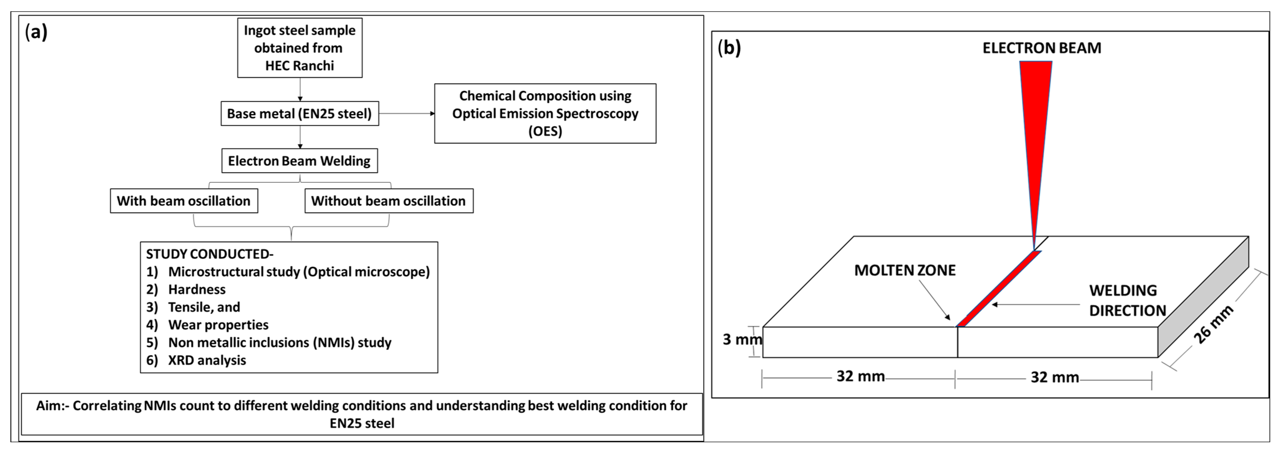
2. Materials and Methods
2.1. The Investigated Base Material
2.2. Experimental Procedure
3. Results and Discussion
3.1. Microstructural Analysis
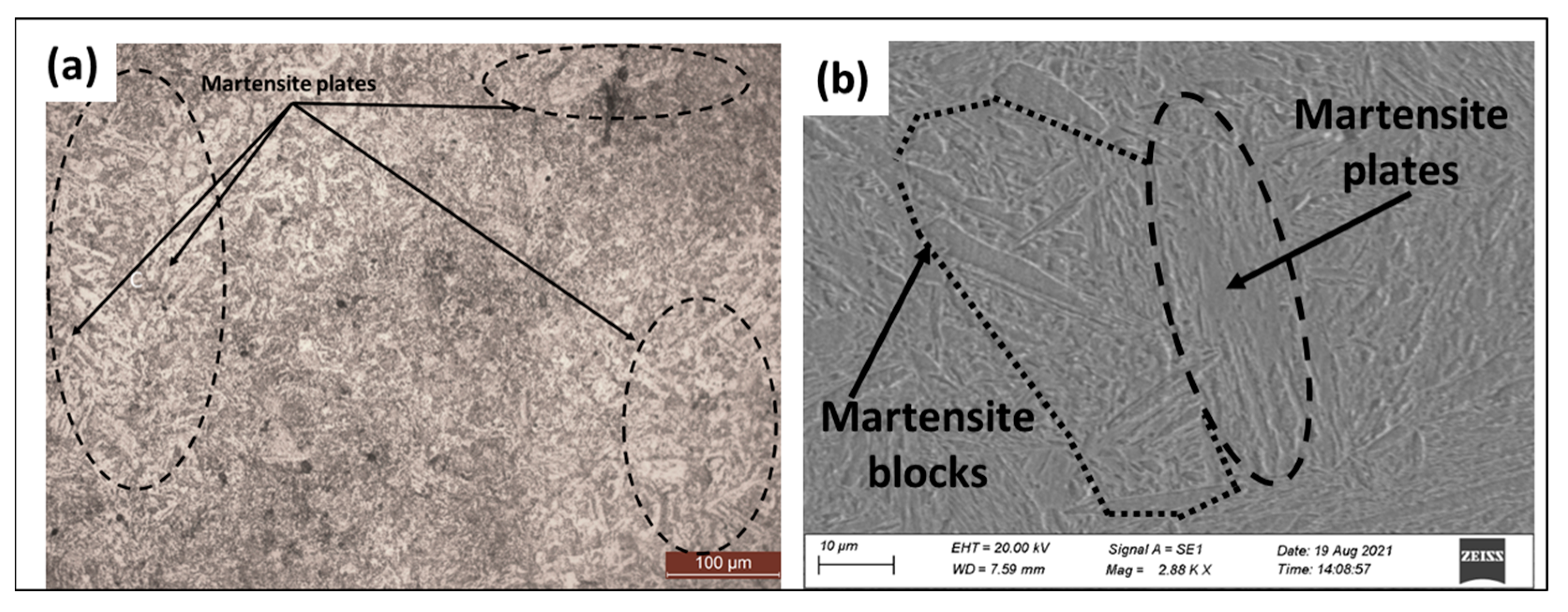
3.1.1. Base Material (BM)
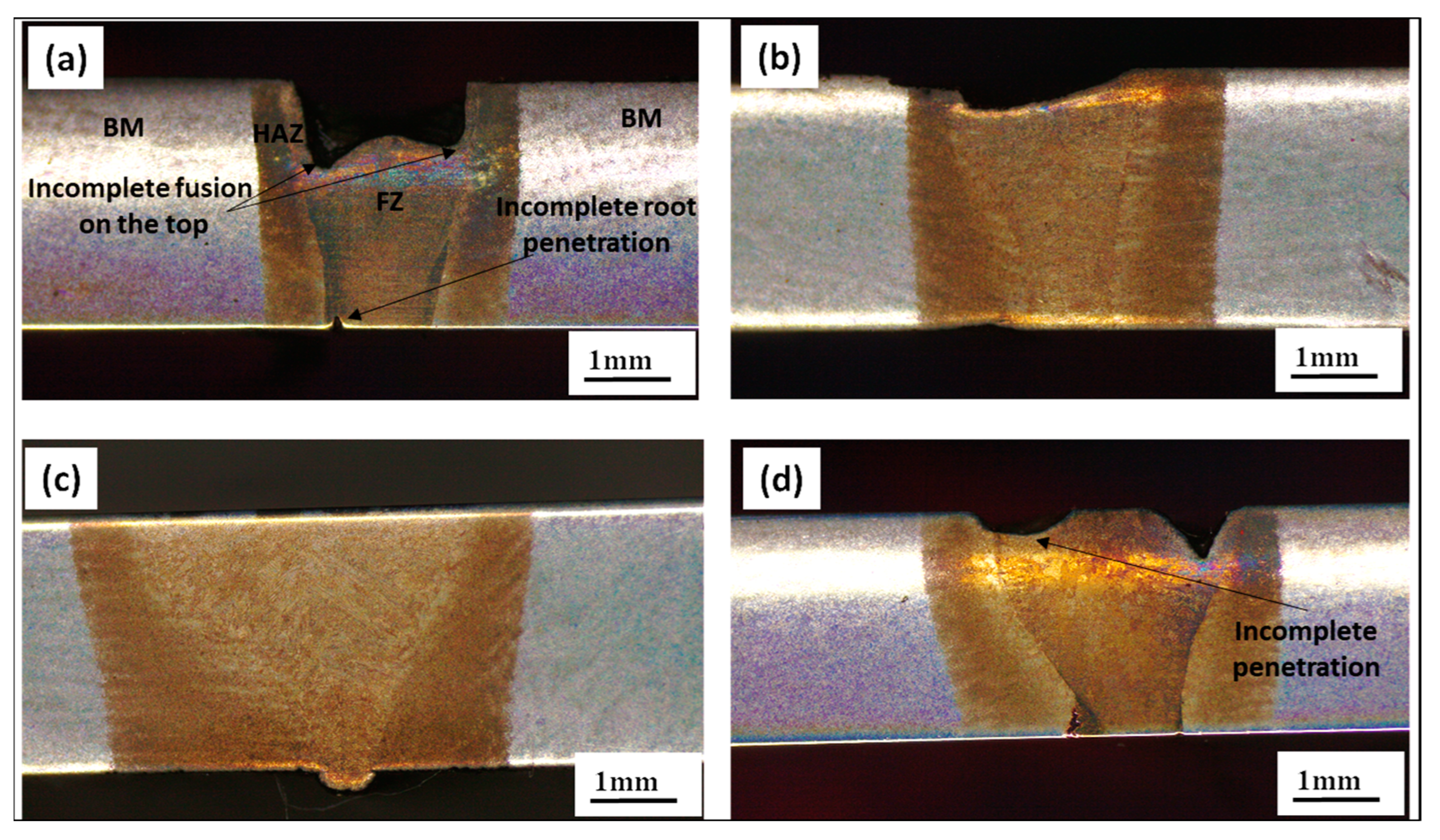
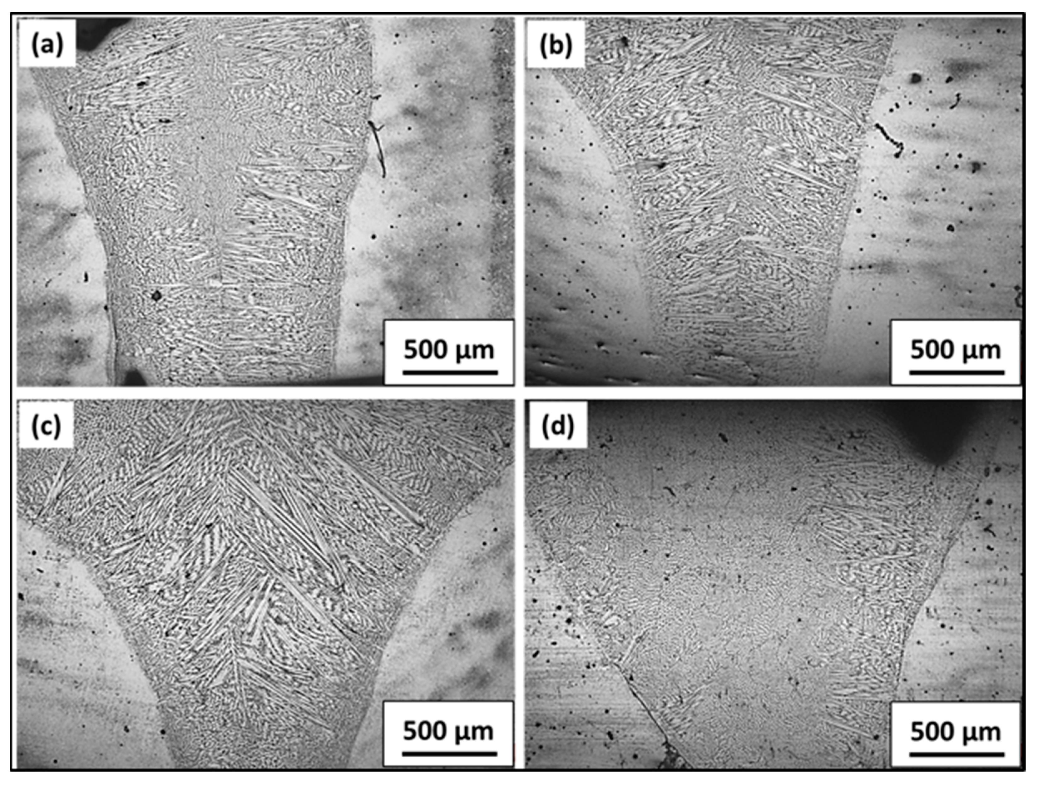
3.1.2. Macroscopic Images after Welding with Base Metal (BM), Heat Affected Zone (HAZ) and Fusion Zone (FZ)
3.1.3. Heat Input Calculation for Different Welding Conditions
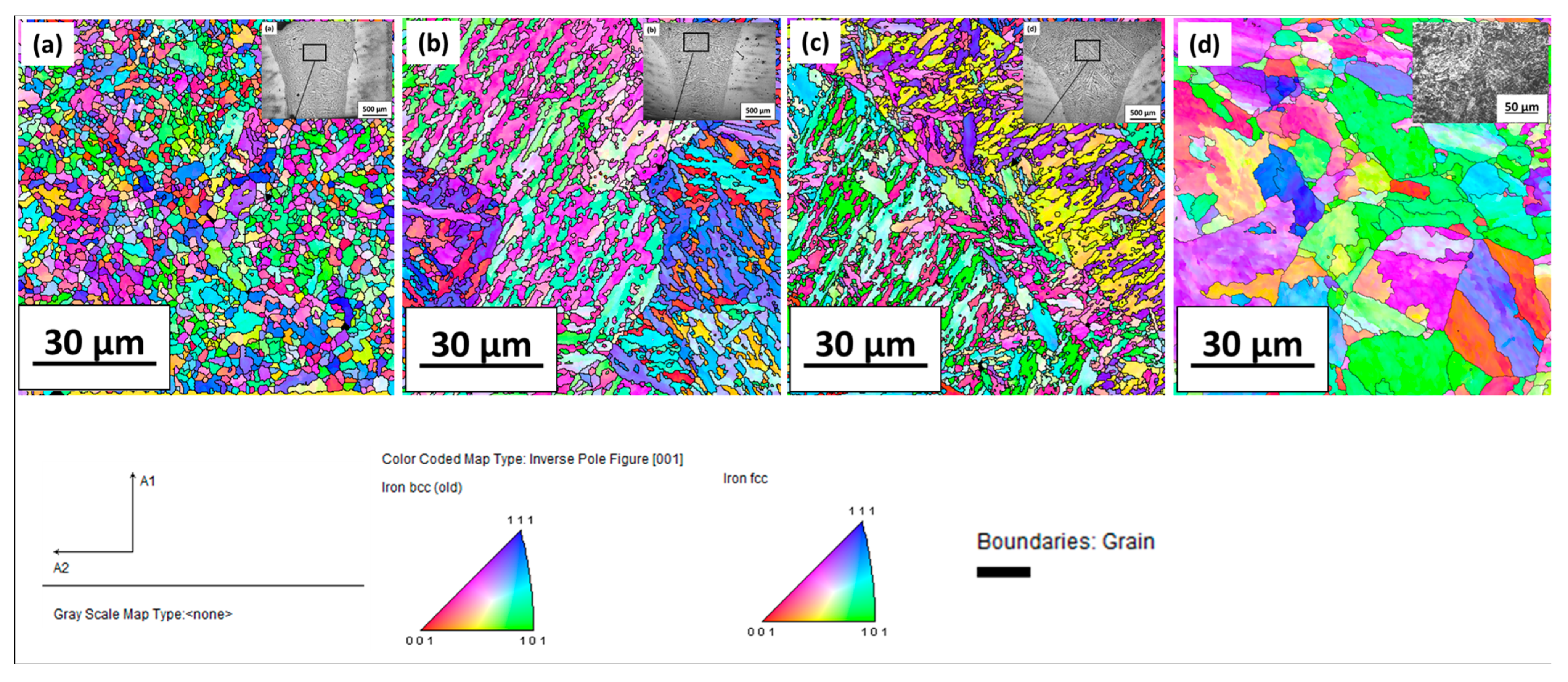
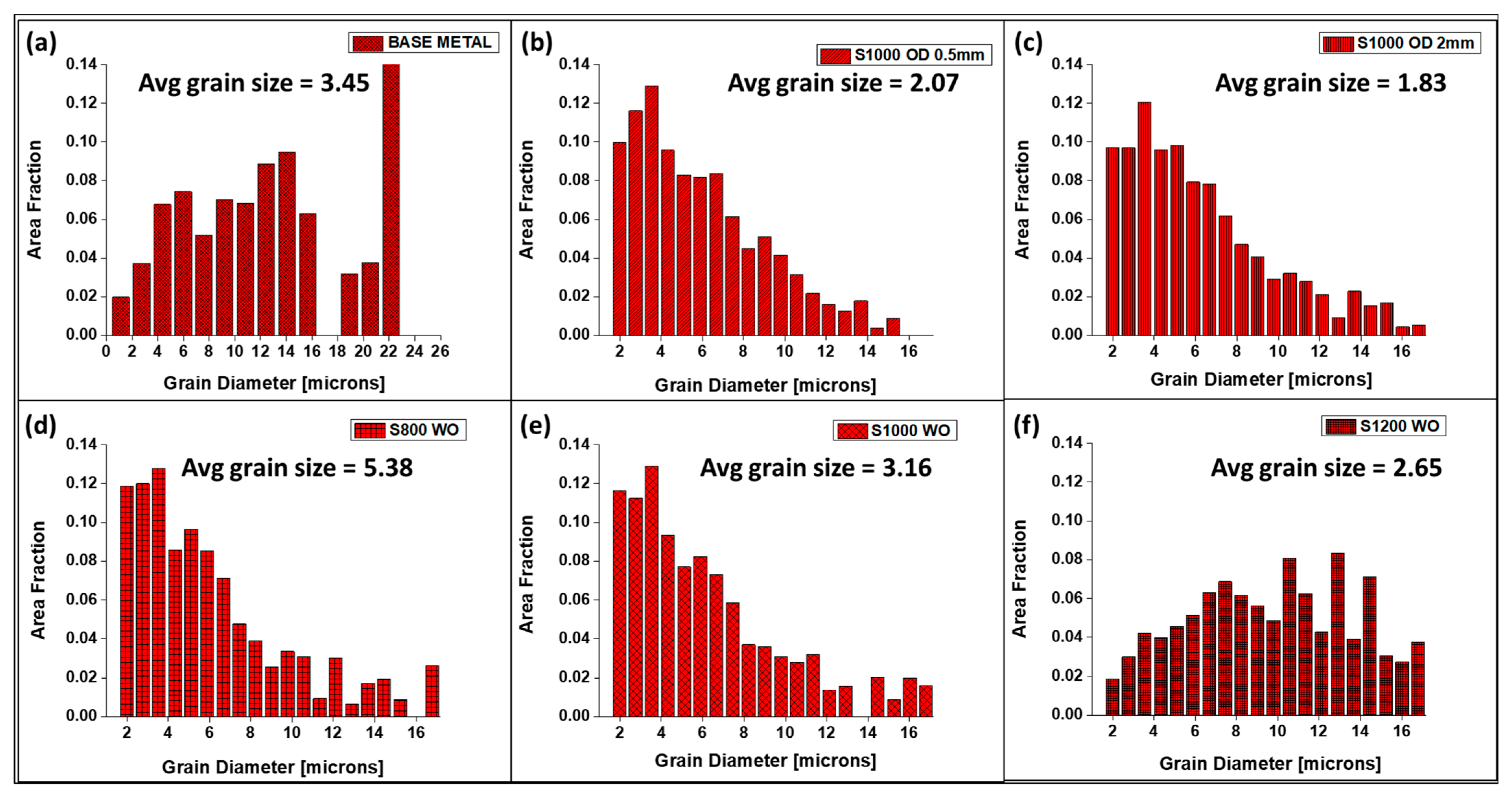
3.1.4. EBSD Analysis of the Welded Region
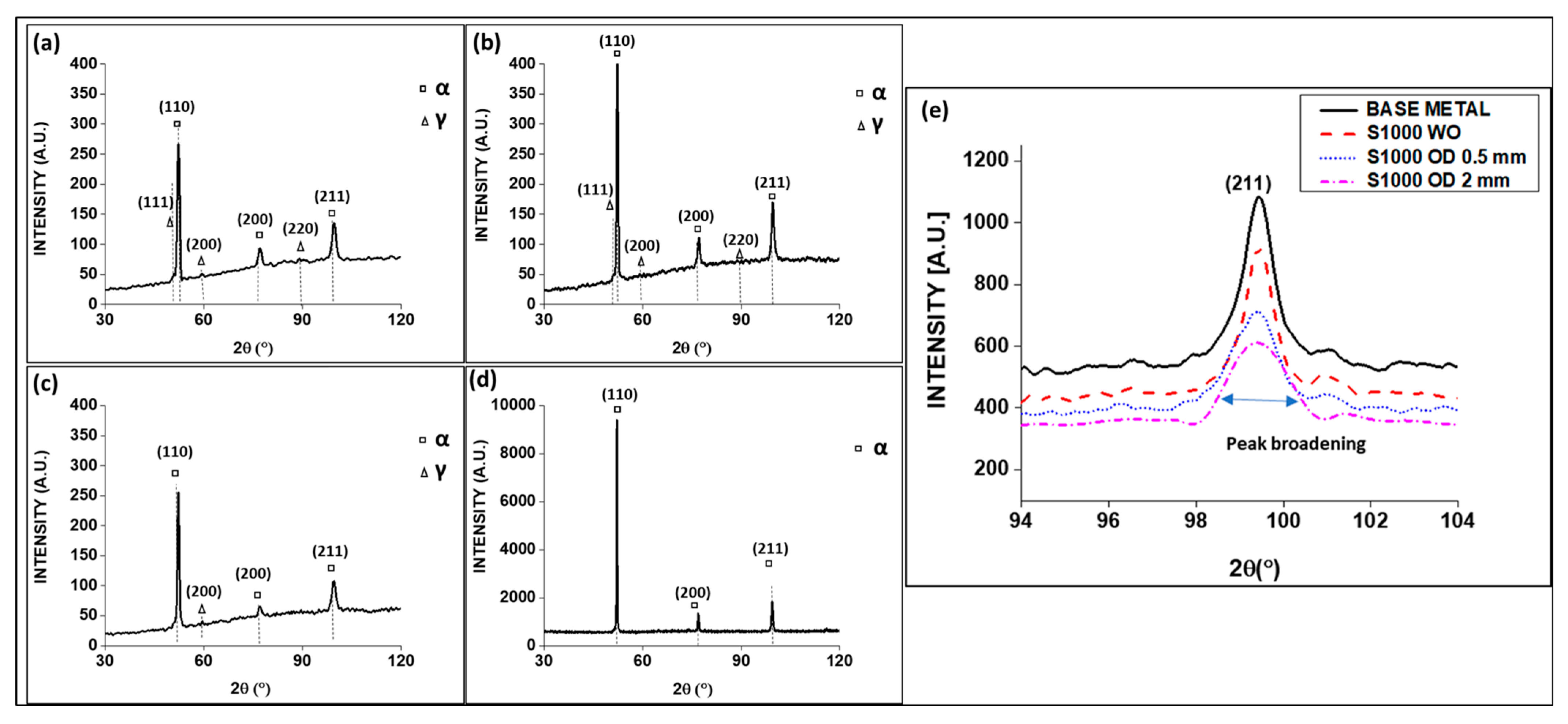
3.2. Residual Stress, Lattice Strain and Dislocation Density from XRD Analysis
3.3. Mechanical Properties
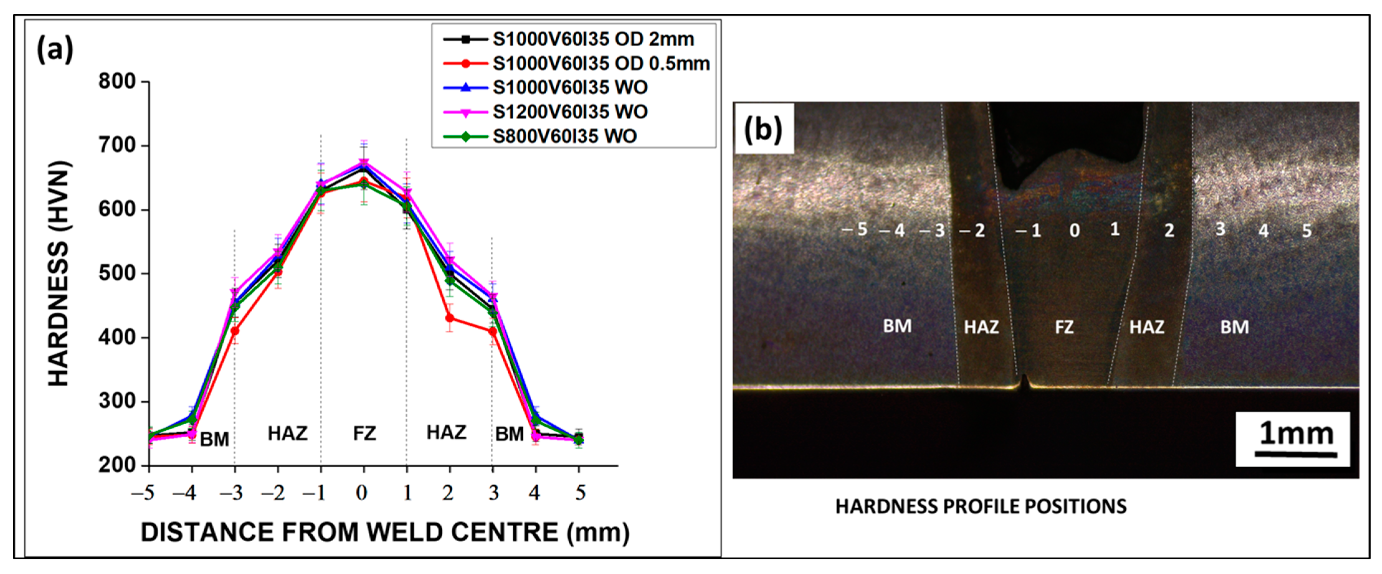
3.3.1. Hardness Measurements
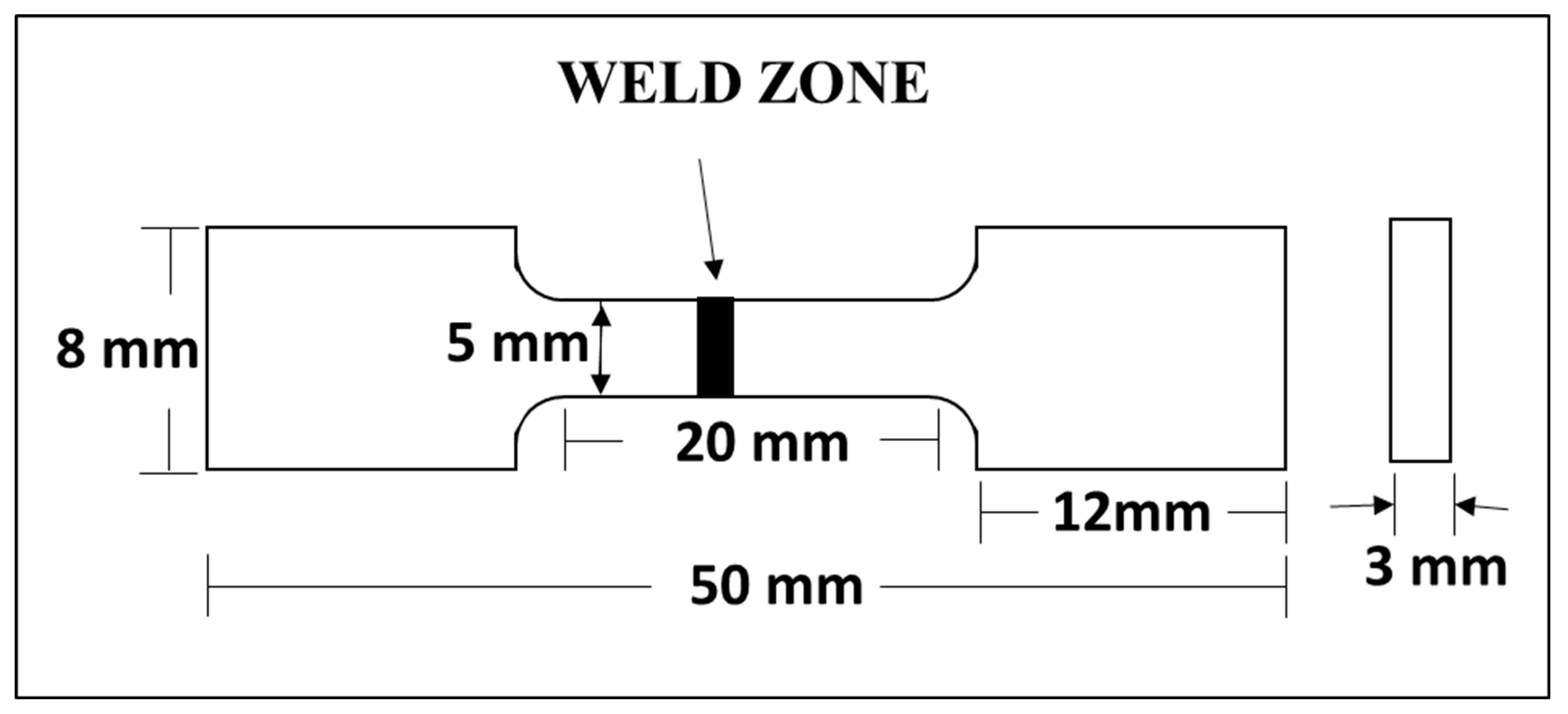
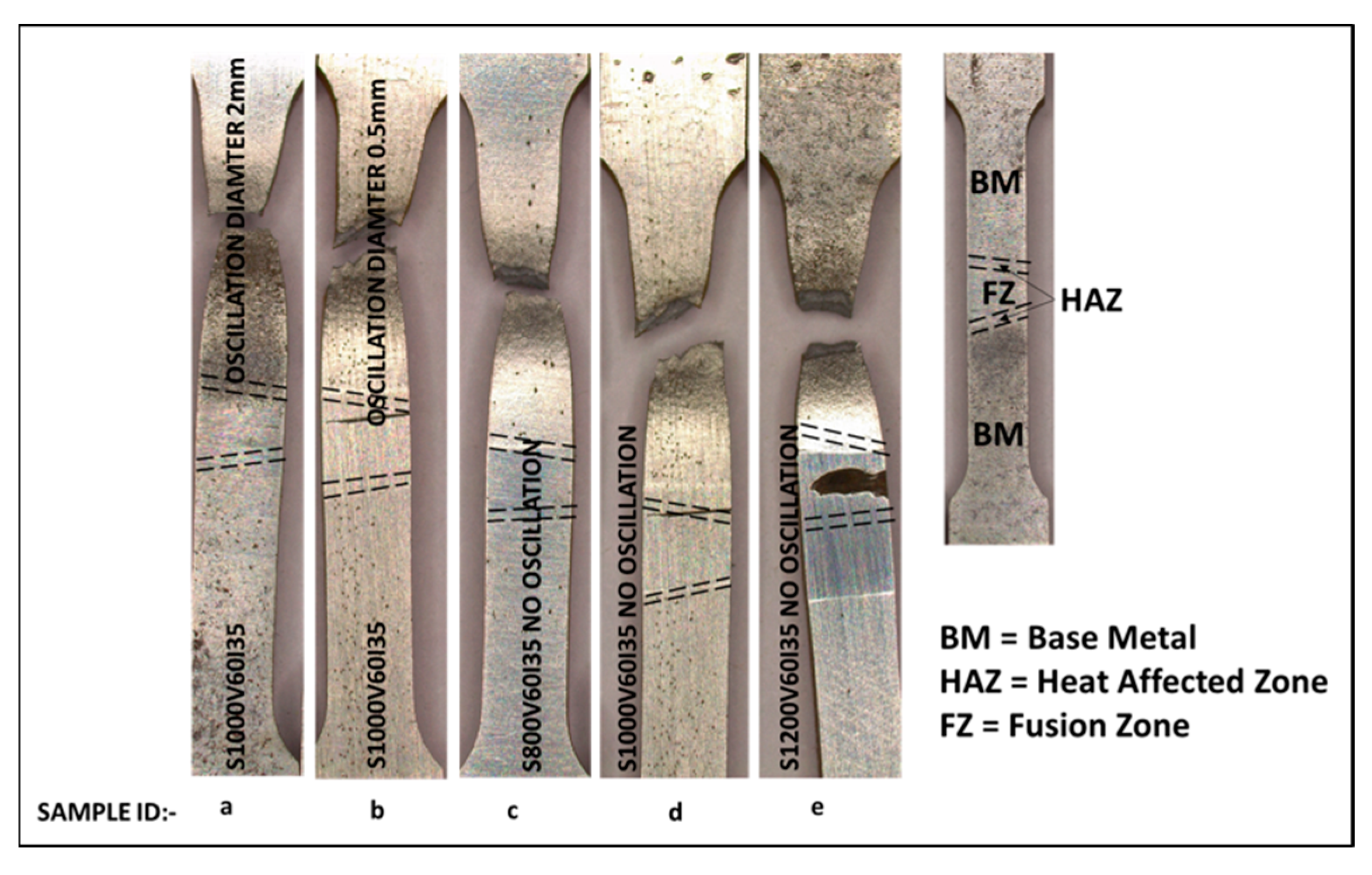
3.3.2. Tensile Test
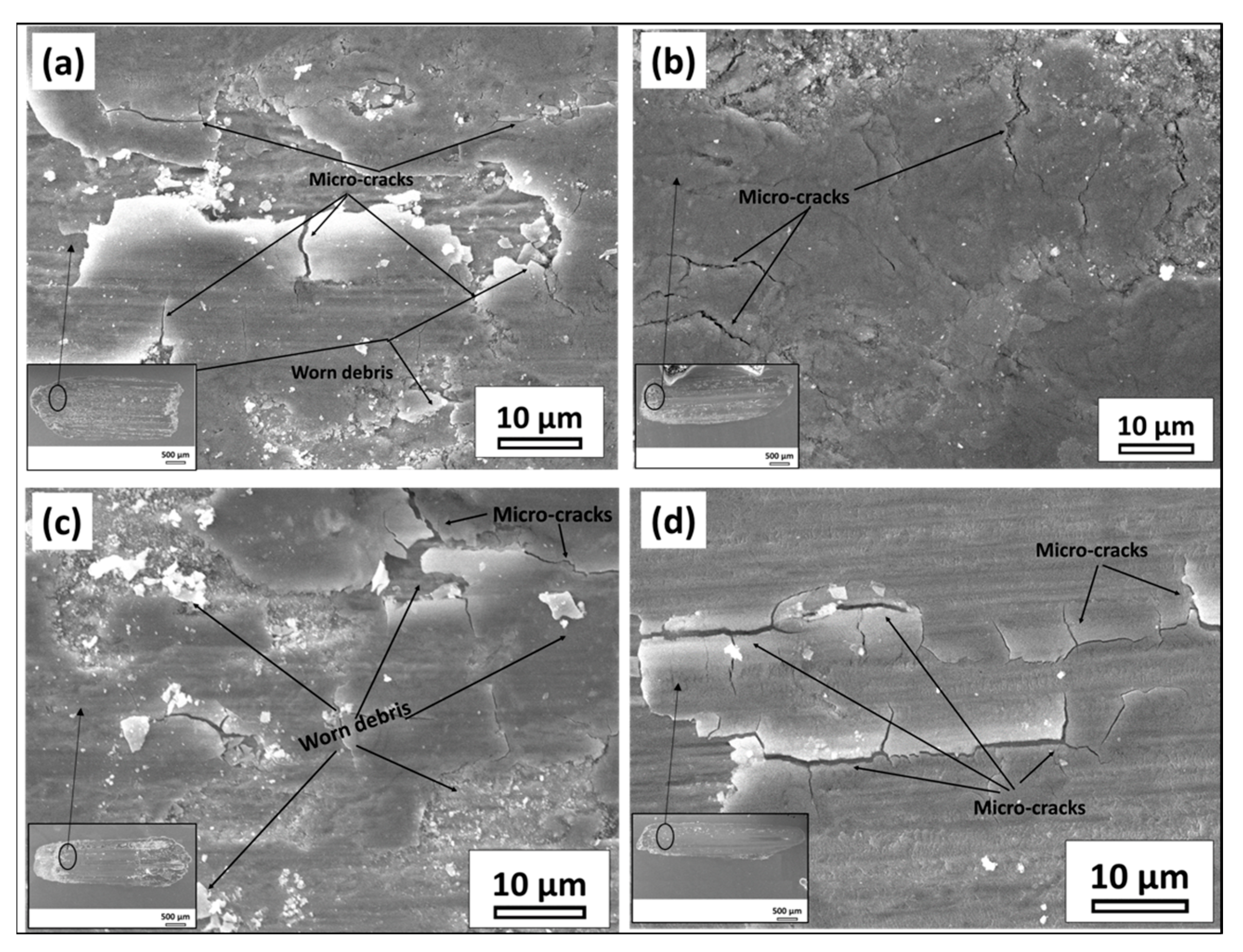
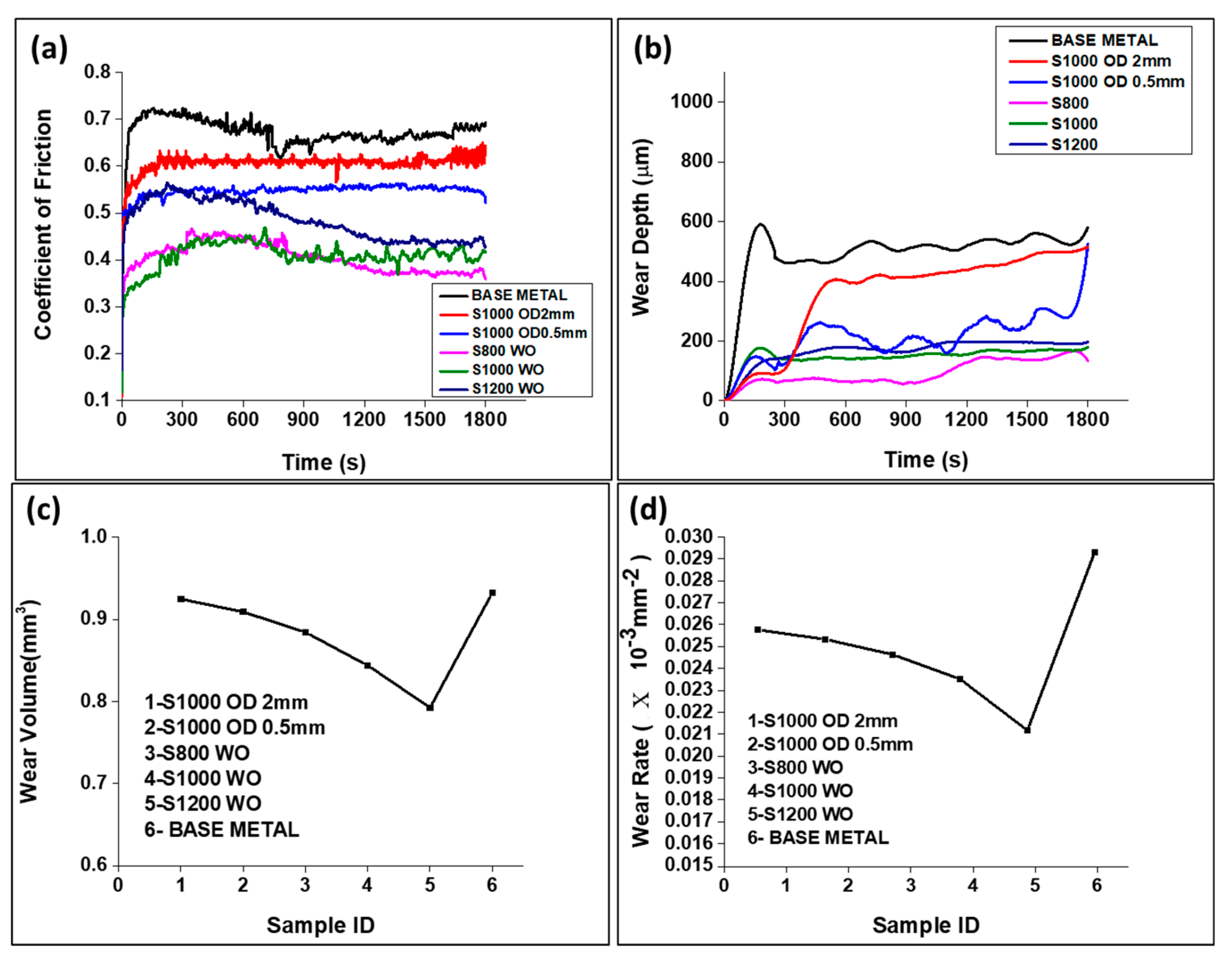
3.4. Wear Test
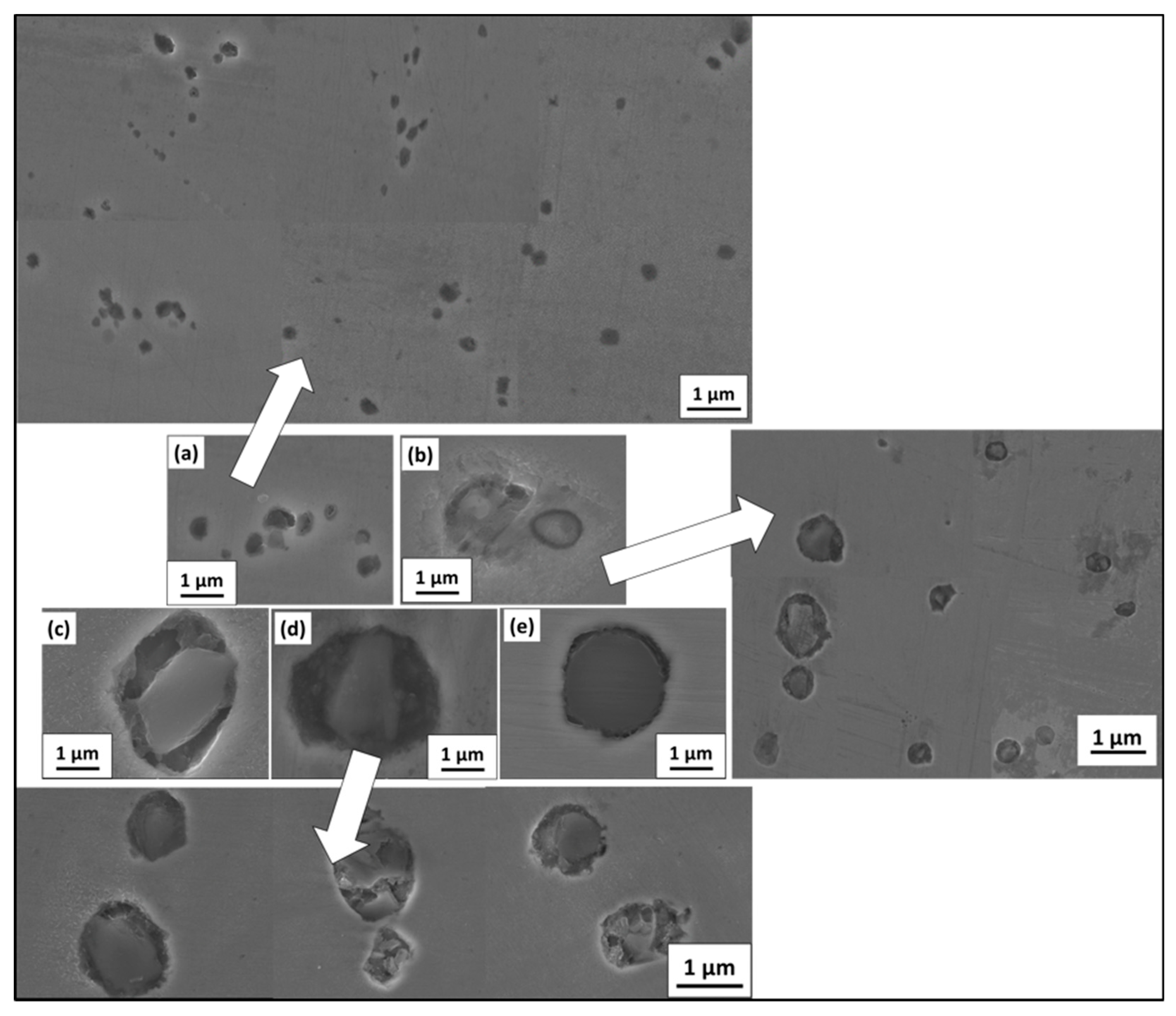
3.5. Study of Non-Metallic Inclusions (NMIs) Size Change with Welding Conditions
4. Conclusions
- (i)
- The calculated heat input rate is found to be extremely low for beam oscillation at a 2-mm oscillation diameter (6 × 10⁻³ kJ/cm) and the highest (1.57 kJ/mm) for the withoutbeam oscillation case case at 800 mm/min scan velocity.
- (ii)
- A large region of equiaxed grains was observed at the center region of the weld prepared with beam oscillation at a 2-mm oscillation diameter, attributed to churning action and heat mixing in the weld seam.
- (iii)
- The fraction of retained austenite (9.35%) was found to be highest in the weld prepared with an oscillating beam at the highest oscillating diameter of 2 mm, which was attributed to heat mixing, a lesser temperature gradient, and thermal stress and stress-induced transformation, such as austenite to martensite. Subsequently, it decreased to 3.27% with decreasing beam oscillation diameter to 0.5 mm. For withoutbeam oscillation case electron beam welding, the fraction of retained austenite was further lowered (0.36%).
- (iv)
- Residual stresses in the weld were found to be compressive in the fusion zone, irrespective of welding conditions.
- (v)
- Nonmetallic inclusion size decreased significantly for welds prepared with beam oscillation, especially at higher oscillating diameters, which was attributed to the fastest cooling rate that retarded the growth of inclusion.
- (vi)
- The hardness and wear properties of welds were found to improve after welding, especially for welds with oscillating beams.
4.1. Limitation of the Present Work
4.2. Future Scope
Author Contributions
Funding
Institutional Review Board Statement
Informed Consent Statement
Data Availability Statement
Acknowledgments
Conflicts of Interest
References
- Wu, C.; Han, S. Mechanical and Microstructure Properties of the Ni-Cr-Mo Modi-Fied Steel by Heat Treatment Process. IOP Conf. IOP Conf. Ser. Mater. Sci. Eng. 2018, 359, 12027–12028. [Google Scholar] [CrossRef]
- Muthukumaran, G.; Rai, A.K.; Gautam, J.; Babu, P.D.; Ranganathan, K.; Bindra, K.S. A Study on Effect of Multiple Laser Shock Peening on Microstructure, Residual Stress, and Mechanical Strength of 2.5 Ni-Cr-Mo (EN25) Low-Alloy Steel. J. Mater. Eng. Perform. 2022, 1–15. [Google Scholar] [CrossRef]
- Chivu, O.; Rontescu, C.; Cicic, D.T.; Bălan, G. The Effects of Reconditioning by Welding of Crankshafts in Automotive Industry. Metalurgija 2016, 55, 55–58. [Google Scholar]
- Schultz, H. Electron Beam Welding; Woodhead Publishing: Cambridge, UK, 1994. [Google Scholar]
- We¸glowski, M.S.; Błacha, S.; Phillips, A. Electron Beam Welding-Techniques and Trends-Review. Vacuum 2016, 130, 72–92. [Google Scholar] [CrossRef]
- Olshanskaya, T.; Belenkiy, V.; Fedoseeva, E.; Koleva, E.; Trushnikov, D. Application of Dynamic Beam Positioning for Creating Specified Structures and Properties of Welded Joints in Electron-Beam Welding. Materials 2020, 13, 2233. [Google Scholar] [CrossRef]
- Błacha, S.; Węglowski, M.S.; Dymek, S.; Kopuściański, M. Microstructural Characterization and Mechanical Properties of Electron Beam Welded Joint of High Strength Steel Grade S690QL. Arch. Met. Mater. 2016, 61, 1193–1200. [Google Scholar] [CrossRef]
- Maurer, W.; Ernst, W.; Rauch, R.; Kapl, S.; Pohl, A.; Krüssel, T.; Vallant, R.; Enzinger, N. Electron Beam Welding of Atmcp Steel with 700 Mpa Yield Strength. Weld. World 2012, 56, 85–94. [Google Scholar] [CrossRef]
- Das, C.R.; Bhaduri, A.K.; Raju, S.; Balakrishnan, R.; Mahadevan, S.; Albert, S.K.; Mastanaiah, P. Influence of electron beam welding parameters on microstructure and Charpy impact properties of boron-added modified 9Cr-1Mo steel weld. Weld. World 2016, 60, 1141–1146. [Google Scholar] [CrossRef]
- Chen, F.; Huo, L.; Zhang, Y.; Zhang, L.; Liu, F.; Chen, G. Effects of electron beam local post-weld heat-treatment on the microstructure and properties of 30CrMnSiNi2A steel welded joints. J. Mater. Process. Technol. 2002, 129, 412–417. [Google Scholar] [CrossRef]
- Arata, Y.; Matsuda, F.; Nakata, K. Quench Hardening and Cracking in Electron Beam Weld Metal of Carbon and Low Alloy Hardenable Steels. Trans. JWSI 1972, 1, 39–51. [Google Scholar]
- Matsuda, F.; Ueyama, T. Solidification crack susceptibility of laser weld metal in 0.2C-Ni-Cr-Mo steels: Effects of bead configuration and S and P contents. Weld. Int. 1993, 7, 686–692. [Google Scholar] [CrossRef]
- Wang, Q.; Liu, X.; Wang, W.; Yang, C.; Xiong, X.; Fang, H. Mixed mode fatigue crack growth behavior of Ni-Cr-Mo-V high strength steel weldments. Int. J. Fatigue 2017, 102, 79–91. [Google Scholar] [CrossRef]
- Wang, Q.; Yan, Z.; Liu, X.; Dong, Z.; Fang, H. Understanding of fatigue crack growth behavior in welded joint of a new generation Ni-Cr-Mo-V high strength steel. Eng. Fract. Mech. 2018, 194, 224–239. [Google Scholar] [CrossRef]
- Liu, S.-D.; Zhu, M.-L.; Zhou, H.-B.; Wan, D.; Xuan, F.-Z. Strain visualization of growing short fatigue cracks in the heat-affected zone of a Ni–Cr–Mo–V steel welded joint: Intergranular cracking and crack closure. Int. J. Press. Vessel. Pip. 2019, 178, 103992. [Google Scholar] [CrossRef]
- Sadeq, B.R.; Sahib, B.S.; Alher, M. Study of the Effects of Welding Process on the Microstructure of Worn Carbon Steel Shaft. IOP Conf. Ser. Mater. Sci. Eng. 2020, 671, 012161. [Google Scholar] [CrossRef]
- Sisodia, R.P.; Gáspár, M. Experimental assessment of microstructure and mechanical properties of electron beam welded S960M high strength structural steel. Manuf. Lett. 2021, 29, 108–112. [Google Scholar] [CrossRef]
- Bai, Q.; Ma, Y.; Kang, X.; Xing, S.; Chen, Z. Study on the welding continuous cooling transformation and weldability of SA508Gr4 steel for nuclear pressure vessels. Int. J. Mater. Res. 2017, 108, 99–107. [Google Scholar] [CrossRef]
- Kar, J.; Roy, S.K.; Roy, G.G. Effect of beam oscillation on electron beam welding of copper with AISI-304 stainless steel. J. Mater. Process. Technol. 2016, 233, 174–185. [Google Scholar] [CrossRef]
- Dinda, S.K.; Sk, B.; Roy, G.G.; Srirangam, P. Microstructure and mechanical properties of electron beam welded dissimilar steel to Fe–Al alloy joints. Mater. Sci. Eng. A 2016, 677, 182–192. [Google Scholar] [CrossRef]
- Nayak, L.J.; Roy, G.G. Role of beam oscillation on electron beam welded zircaloy-4 butt joints. Sci. Technol. Weld. Join. 2021, 26, 478–486. [Google Scholar] [CrossRef]
- Yang, Z.; He, J. Numerical investigation on fluid transport phenomena in electron beam welding of aluminum alloy: Effect of the focus position and incident beam angle on the molten pool behavior. Int. J. Therm. Sci. 2021, 164, 106914. [Google Scholar] [CrossRef]
- Wang, S.; Wu, X. Investigation on the microstructure and mechanical properties of Ti–6Al–4V alloy joints with electron beam welding. Mater. Des. 2012, 36, 663–670. [Google Scholar] [CrossRef]
- Wang, X.; Gong, X.; Chou, K. Scanning Speed Effect on Mechanical Properties of Ti-6Al-4V Alloy Processed by Electron Beam Additive Manufacturing. Procedia Manuf. 2015, 1, 287–295. [Google Scholar] [CrossRef] [Green Version]
- Doong, J.L.; Chi, J.M.; Tan, Y.H. Fracture Toughness Behaviour in AISI 4130 Steel of Electron Beam Welding. Eng. Fract. Mech. 1990, 36, 999–1006. [Google Scholar]
- Xia, X.; Wu, J.; Liu, Z.; Shen, X.; Ma, J.; Liu, Z. Study of microstructure difference properties of electron beam welds with beam oscillation of 50 mm 316L in CFETR. Fusion Eng. Des. 2018, 138, 339–346. [Google Scholar] [CrossRef]
- Sun, J.; Zou, X.; Matsuura, H.; Wang, C. Effect of Heat Input on Inclusion Evolution Behavior in Heat-Affected Zone of EH36 Shipbuilding Steel. JOM 2018, 70, 946–950. [Google Scholar] [CrossRef]
- Chen, Z.; Loretto, M.H.; Cochrane, R.C. Nature of Large Precipitates in Tita-Nium-Containing HSLA Steels. Mater. Sci. Technol. 1987, 3, 836–844. [Google Scholar] [CrossRef]
- Wan, X.; Zhou, B.; Nune, K.C.; Li, Y.; Wu, K.; Li, G. In-situ microscopy study of grain refinement in the simulated heat-affected zone of high-strength low-alloy steel by TiN particle. Sci. Technol. Weld. Join. 2016, 22, 343–352. [Google Scholar] [CrossRef]
- Biswas, S.; Reddy, G.M.; Mohandas, T.; Murthy, C.V.S. Residual stresses in Inconel 718 electron beam welds. J. Mater. Sci. 2004, 39, 6813–6815. [Google Scholar] [CrossRef]
- Wang, L.; Gao, M.; Zhang, C.; Zeng, X. Effect of beam oscillating pattern on weld characterization of laser welding of AA6061-T6 aluminum alloy. Mater. Des. 2016, 108, 707–717. [Google Scholar] [CrossRef]
- Cullity, B.D. Elements of X-ray Diffraction; Addison-Wesley Educational: Boston, MA, USA, 1956. [Google Scholar]
- Mote, V.; Purushotham, Y.; Dole, B. Williamson-Hall analysis in estimation of lattice strain in nanometer-sized ZnO particles. J. Theor. Appl. Phys. 2012, 6, 1–8. [Google Scholar] [CrossRef] [Green Version]
- Kalsoom, U.-I.; Bashir, S.; Ali, N. SEM, AFM, EDX and XRD analysis of laser ablated Ti in nonreactive and reactive ambient environments. Surf. Coat. Technol. 2013, 235, 297–302. [Google Scholar] [CrossRef]
- Singh, J.K.; Roy, G.G.; Prakash, P.N.; Rai, A.; Manna, I.; Kanjilal, D.; Majumdar, J.D. Effect of beam oscillation on microstructure, defect density, and resistivity of electron beam welded niobium. Weld. World 2022, 66, 2483–2495. [Google Scholar] [CrossRef]
- Ramana, P.V.; Reddy, G.M.; Mohandas, T.; Gupta, A. Microstructure and residual stress distribution of similar and dissimilar electron beam welds–Maraging steel to medium alloy medium carbon steel. Mater. Des. 2009, 31, 749–760. [Google Scholar] [CrossRef]
- Sharma, S.K.; Biswas, K.; Majumdar, J.D. Studies on Electron Beam Surface Remelted Inconel 718 Superalloy. Met. Mater. Int. 2020, 27, 5360–5373. [Google Scholar] [CrossRef]
- Momoh, I.M.; Dongo, E.I.; Olusunle, S.O.O.; Ogundare, O. Weldability Assessment of Dual Phase Medium Carbon Low Alloy Steel. Int. J. Sci. Technol. 2012, 1, 569–572. [Google Scholar]
- Neto, F.S.; Neves, D.; Silva, O.; Lima, M.; Abdalla, A. An Analysis of the Mechanical Behavior of AISI 4130 Steel after TIG and Laser Welding Process. Procedia Eng. 2015, 114, 181–188. [Google Scholar] [CrossRef] [Green Version]
- Jamari, J.; Ammarullah, M.I.; Santoso, G.; Sugiharto, S.; Supriyono, T.; Prakoso, A.T.; Basri, H.; van der Heide, E. Computational Contact Pressure Prediction of CoCrMo, SS 316L and Ti6Al4V Femoral Head against UHMWPE Acetabular Cup under Gait Cycle. J. Funct. Biomater. 2022, 13, 64. [Google Scholar] [CrossRef]
- Basak, S.; Sharma, S.K.; Mondal, M.; Sahu, K.K.; Gollapudi, S.; Majumdar, J.D.; Hong, S.-T. Electron Beam Surface Treatment of 316L Austenitic Stainless Steel: Improvements in Hardness, Wear, and Corrosion Resistance. Met. Mater. Int. 2020, 27, 953–961. [Google Scholar] [CrossRef]
- Sharma, S.K.; Biswas, K.; Majumdar, J.D. Wear behaviour of Electron beam surface melted Inconel 718. Procedia Manuf. 2019, 35, 866–873. [Google Scholar] [CrossRef]
- Sufizadeh, A.R.; Mousavi, S.A.A.A. Metallurgical and Mechanical Research on Dissimilar Electron Beam Welding of AISI 316L and AISI 4340. Adv. Mater. Sci. Eng. 2016, 2016, 1–11. [Google Scholar] [CrossRef] [Green Version]


| C | Si | Mn | Ni | Cr | Mo | S | P | Fe |
|---|---|---|---|---|---|---|---|---|
| 0.32 | 0.28 | 0.56 | 2.4 | 0.72 | 0.62 | 0.02 | 0.025 | 95.055 |
| S.No. | Sample ID | Speed (S) (mm/min) | Voltage (V) (kV) | Current (I) (mA) | With Beam Oscillation | Without Beam Oscillation (WO) | |
|---|---|---|---|---|---|---|---|
| Oscillation Diameter (OD) (mm) | Oscillation Frequency (Hz) | ||||||
| 1. | S1000V60I35 OD 2 mm | 1000 | 60 | 35 | 2 | 300 | No |
| 2. | S1000V60I35 OD 0.5 mm | 1000 | 60 | 35 | 0.5 | 300 | No |
| 3. | S800V60I35 WO | 800 | 60 | 35 | - | - | Yes |
| 4. | S1000V60I35 WO | 1000 | 60 | 35 | - | - | Yes |
| 5. | S1200V60I35 WO | 1200 | 60 | 35 | - | - | Yes |
| Serial No. | Sample ID | Measured Weld Bead (FZ) (mm) | Calculated Heat Input (Q) (kJ/cm) |
|---|---|---|---|
| 1. | S1000V60I35 OD 2 mm | 2.077 | 0.006 |
| 2. | S1000V60I35 OD 0.5 mm | 2.617 | 0.024 |
| 3. | S800V60I35 WO | 2.924 | 1.57 |
| 4. | S1000V60I35 WO | 2.813 | 1.26 |
| 5. | S1200V60I35 WO | 2.626 | 1.05 |
| Serial No. | Sample ID | Lattice Strain % | Residual Stress (MPa) | Dislocation Density (mm−2) | Hardness of FZ (HVN) | Wear Rate (10−3) (mm−2) | NMIs Size Range (µm) |
|---|---|---|---|---|---|---|---|
| 1. | S1000V60I35 OD 2 mm | 0.489 | −414.4 ± 54 | 6.34 × 10¹⁵ | 665 ± 5 | 0.02576 | 0.1–0.52 |
| 2. | S1000V60I35 OD 0.5 mm | 0.341 | −300 ± 40 | 3.19 × 10¹⁵ | 645 ± 5 | 0.02533 | 0.56–1.78 |
| 3. | S800V60I35 WO | 0.115 | −288.59 ± 98 | 3.98 × 10¹⁴ | 640 ± 5 | 0.02363 | 1–5 |
| 4. | S1000V60I35 WO | 0.124 | −215.4 ± 13 | 5.44 × 10¹⁴ | 670 ± 5 | 0.02351 | 1–5 |
| 5. | S1200V60I35 WO | 0.236 | −198.6 ± 88 | 9.82 × 10¹⁴ | 675 ± 5 | 0.02117 | 1–3 |
| 6. | BASE METAL | 0.096 | −150.71 ± 19 | 1.66 × 10¹⁴ | 240 ± 5 | 0.02931 | 5–10 |
Disclaimer/Publisher’s Note: The statements, opinions and data contained in all publications are solely those of the individual author(s) and contributor(s) and not of MDPI and/or the editor(s). MDPI and/or the editor(s) disclaim responsibility for any injury to people or property resulting from any ideas, methods, instructions or products referred to in the content. |
© 2023 by the authors. Licensee MDPI, Basel, Switzerland. This article is an open access article distributed under the terms and conditions of the Creative Commons Attribution (CC BY) license (https://creativecommons.org/licenses/by/4.0/).
Share and Cite
Singh, V.; Srirangam, P.; Roy, G.G. Effect of Beam Oscillation on Microstructure and Mechanical Properties of Electron Beam Welded EN25 Steel. Materials 2023, 16, 2717. https://doi.org/10.3390/ma16072717
Singh V, Srirangam P, Roy GG. Effect of Beam Oscillation on Microstructure and Mechanical Properties of Electron Beam Welded EN25 Steel. Materials. 2023; 16(7):2717. https://doi.org/10.3390/ma16072717
Chicago/Turabian StyleSingh, Vasundhara, Prakash Srirangam, and Gour Gopal Roy. 2023. "Effect of Beam Oscillation on Microstructure and Mechanical Properties of Electron Beam Welded EN25 Steel" Materials 16, no. 7: 2717. https://doi.org/10.3390/ma16072717