Article

Multifunctional TiO2 Nanotube-Matrix Composites with Enhanced Photocatalysis and Lithium-Ion Storage Performances

Shanghai Institute of Intelligent Electronics and Systems, College of Science, Donghua University, Shanghai 201620, China
*
Authors to whom correspondence should be addressed.
Materials 2023, 16(7), 2716; https://doi.org/10.3390/ma16072716
Submission received: 26 February 2023 / Revised: 25 March 2023 / Accepted: 27 March 2023 / Published: 29 March 2023

Abstract

:
As a multifunctional material, TiO2 shows excellent performance in catalytic degradation and lithium-ion storage. However, high electron-hole pair recombination, poor conductivity, and low theoretical capacity severely limit the practical application of TiO2. Herein, TiO2 nanotube (TiO2 NT) with a novel double-layer honeycomb structure were prepared by two-step electrochemical anodization. Honeycombed TiO2 NT arrays possess clean top surfaces and a long-range ordering, which greatly facilitates the preparation of high-performance binary and ternary materials. A binary TiO2 nanotube@Au nanoparticle (TiO2 NT@Au NP) composite accompanied by appropriately concentrated and uniformly distributed gold particles was prepared in this work. Interestingly, the TiO2 nanotube@Au nanoparticle (TiO2 NT@Au NP) composites not only showed the excellent catalytic degradation effect of methylene blue, but also demonstrated large lithium-ion storage capacity (310.6 μAh cm−2, 1.6 times of pristine TiO2 NT). Based on the realization of the controllable fabrication of binary TiO2 nanotube@MoS2 nanosheet (TiO2 NT@MoS2 NS) composite, ternary TiO2 nanotube@MoS2 nanosheet@Au nanoparticle (TiO2 NT@MoS2 NS@Au NP) composite with abundant defects and highly ordered structure was also innovatively designed and fabricated. As expected, the TiO2 NT@MoS2 NS@Au NP anode exhibits extremely high initial discharge specific capacity (487.4 μAh cm−2, 2.6 times of pristine TiO2 NT) and excellent capacity retention (81.0%).

1. Introduction

With the booming development of science and technology, the environment and energy issues attracted more and more attention. As a multifunctional semiconductor material, TiO2 can be used as catalyst and anode in photocatalytic degradation and lithium batteries [1,2,3]. TiO2 has the advantages of being non-toxic, safety, and stability, so it is widely pursued by researchers [4]. The construction of various nanostructures (e.g., nanoparticle, nanowire, nanorod, and nanotube) brought the advantage of large specific surface area to TiO2 nanomaterials, which is more conducive to the improvement of TiO2 nanomaterials’ catalytic and electrochemical properties [3,5,6]. In particular, the TiO2 nanotube prepared by electrochemical anodizing has a self-organized morphology, and the tubular structure shortens the transmission path of electrons and ions, greatly increases the specific surface area, making the TiO2 nanotube an alternative catalyst and anode [3,7]. However, high electron-hole pair recombination, poor conductivity, and inferior theoretical capacity (335 mAh g−1) limit the practical application of TiO2 nanotubes in catalysis and lithium-ion battery [8,9,10].
As a widely known metal, Au has the characteristics of inactivity and excellent conductivity. While the metal/semiconductor (Au/TiO2) junction appears, Au as the separation center can decrease the recombination of electron-hole pairs in the TiO2 and overcome shortcoming of high electron-hole pair recombination of TiO2 semiconductor materials, leading to the enhanced degradation ability of organic pollutants [11,12,13]. On the other hand, Au is a good conductive additive, which can significantly increase the conductivity of TiO2 anode. The addition of Au will increase the transfer rate of ions and electrons in TiO2 nanotubes, but the improvement of lithium capacity is very limited [14,15,16]. Thus, it is still a challenge to further improve the TiO2 nanotube-matrix composite electrode’s capacity. Molybdenum sulfide (MoS2), as a typical two-dimensional material, is considered as an ideal candidate anode for lithium batteries because of its large theoretical specific capacity (670 mAh g−1) and high safety [17,18,19]. However, the large volume expansion of MoS2 in the process of charging/discharging leads to the large capacity instability of lithium batteries [20,21]. Considering the high stability of TiO2, many researchers combined TiO2 with MoS2, which combined the advantages of the two components to prepare high-performance composite lithium battery anode [17,22]. In previous studies, TiO2@MoS2 composites were mostly prepared using one-step anodization TiO2 nanotubes as a matrix. However, such traditional nanotube’s disordered top surface and distinct nanotube length lead to random accumulation of MoS2 in the composite [23,24]. Therefore, developing a clean top surface and long-range ordered TiO2 nanotube matrix is very important for the preparation and performance of composite materials.
In this work, the TiO2 nanotube (TiO2 NT) with a double-layer honeycomb structure was prepared by two-step electrochemical anodization. Fancifully, honeycombed TiO2 NT differ from traditional one-step oxidation nanotubes in that they have a clean top surface and a long-range ordering. In addition, honeycombed TiO2 NT arrays have porous properties and large specific surface areas, which contribute to the preparation of high-performance composites by combining them with Au nanoparticles and MoS2 nanosheets. High performance multifunctional TiO2 nanotube@Au nanoparticle (TiO2 NT@Au NP) composites accompanied by uniformly distributed Au nanoparticles were successfully prepared in this work. Excitedly, the TiO2 NT@Au NP composite shows excellent catalytic degradation effect, due to the existence of Au particles with appropriate concentration in composite. In addition, while the TiO2 NT@Au NP composite is used as a lithium-ion battery’s anode, it also demonstrates large initial specific capacity (310.6 μAh cm−2, 1.6 times of pristine TiO2 NT) and high initial coulomb efficiency (76.5%). Furthermore, ternary TiO2 nanotube@MoS2 nanosheet@Au nanoparticle (TiO2 NT@MoS2 NS@Au NP) anode was also successfully designed and synthesized in this work. Compared with traditional binary materials, such ternary material possesses abundant defects and highly ordered structure, improving the kinetics properties and lithium storage capacity of TiO2 NT@MoS2 NS@Au NP composite. Thus, the as-designed TiO2 NT@MoS2 NS@Au NP anode exhibited remarkable cycle stability (81.0% capacity retention) and large lithium-ion capacity (487.4 μAh cm−2, 2.6 times of pristine TiO2 NT).

2. Materials and Methods

2.1. Synthesis of TiO2 Nanotube (TiO2 NT)

Based on previous work, the electrochemical anodization method was used to prepare TiO2 nanotube array [2]. First anodizing process was carried out at 60 V for 60 min, and then the TiO2 NT array was peeled off by sonication. Subsequently, the second electrochemical anodization was implemented for 20 min (60 min) at a constant voltage of 60 V. Then, the secondary oxidized TiO2 nanotube was annealed at 450 °C in air atmosphere for 2 h to obtain the as-annealed secondary oxidized TiO2 nanotubes, named TiO2 NT, which was used as a matrix to prepare subsequent composites.

2.2. Synthesis of TiO2 Nanotube@Au Nanoparticle (TiO2 NT@Au NP) and TiO2 Nanotube@MoS2 Nanosheet (TiO2 NT@MoS2 NS)

Next, 1 mL of sodium citrate aqueous solution (1.5 wt%) and 1 mL of 1.2 mM polyvinylpyrrolidone (PVP, 58,000 g/mol) aqueous solution were added to 43 mL ultra-pure water. The mixed solution was transferred into a round bottom flask; meanwhile, the as-prepared TiO2 NT was suspended in the mixed solution. The mixed aqueous solution was heated in the oil bath at 115 °C until it boiled, and then we added 5 mL of 2.5 mM tetrachloroauric acid aqueous solution into the reactor. Under magnetic stirring, the reaction duration was 60 min. Then, we took out the titanium foil attached with TiO2 NT array and washed it twice with ethanol and pure water, respectively. The obtained TiO2 nanotube@Au nanoparticle (TiO2 NT@Au NP) composite was dried in the atmosphere.
In order to prepare molybdenum oxide precursor solution, 10 mL of hydrogen peroxide (30 wt%) was slowly dropped into 0.0083 mol of molybdenum powder in an ice water bath. Subsequently, magnetic stirring was carried out for 4 h to obtain fully reacted molybdenum oxide precursor solution. After that, the molybdenum oxide precursor solution was dropped into 25 mL of 0.6 M thiourea aqueous solution under magnetic stirring. After 60 min of magnetic stirring, a uniform and stable mixed solution was prepared. Next, 0.5 g (0.1 g, 0.3 g) of polyvinylpyrrolidone (PVP, 58,000 g/mol) was dissolved in 5 mL of ultrapure water to prepare the surfactant solution. As-prepared TiO2 NT array was placed at the bottom of the 50 mL Teflon-lined stainless steel autoclave, then the surfactant solution and the mixed solution was poured into the autoclave in turn. After sealing, the autoclave was subjected to reaction at 200 ℃ for 24 h. After the hydrothermal reaction, the autoclave was naturally cooled, and then the titanium foil attached with the composite material was picked out and washed with ethanol and ultrapure water for three times, respectively, followed by natural drying in the air atmosphere. In order to obtain a perfectly bonded composite, the dried sample was annealed at 450 ℃ in argon atmosphere, and finally the TiO2 nanotube@MoS2 nanosheet (TiO2 NT@MoS2 NS) composite was obtained.

2.3. Synthesis of TiO2 Nanotube@MoS2 Nanosheet@Au Nanoparticle (TiO2 NT@MoS2 NS@Au NP)

The synthesis method of TiO2 NT@MoS2 NS@Au NP composite was similar to that of TiO2 NT@Au NP, except that the TiO2 NT array was replaced by TiO2 NT@MoS2 NS.

2.4. Photocatalytic Degradation Measurement

The photocatalysis degradation of methylene blue (MB, 2.5 mL, 3.5 × 10⁻⁶ mol/L) using TiO2 NT (20 min or 60 min)@Au NP catalysts was tested [2]. The variation in MB concentration with light irradiation (300 W Xe-lamp) time was used to characterize the catalytic effect of TiO2 NT@Au NP catalysts.

2.5. Electrochemical Evaluation

Electrochemical characteristics of as-prepared samples were explored using CR2016 coin-type half cells. All the samples were directly used as binder-free anodes with the area of 1.5 cm2, and the counter electrodes were lithium foils. The binder-free anode and lithium foil were separated via Celgard 2400 separator membrane in cells. A solution of LiPF6 (1 M, EC:DMC = 1:1 vol%) was used as cells’ electrolyte. To ensure the adequately diffusion of the electrolyte, all sealed cells need to be stood for 12 h before measuring. The LAND CT2001A was used for the galvanostatic charging/discharging test, within the potential of 0.1–3.0 V. Cyclic voltammograms (CVs) were tested by an electrochemical workstation (CHI 660e) under 0.1 mV/s.

3. Results and Discussion

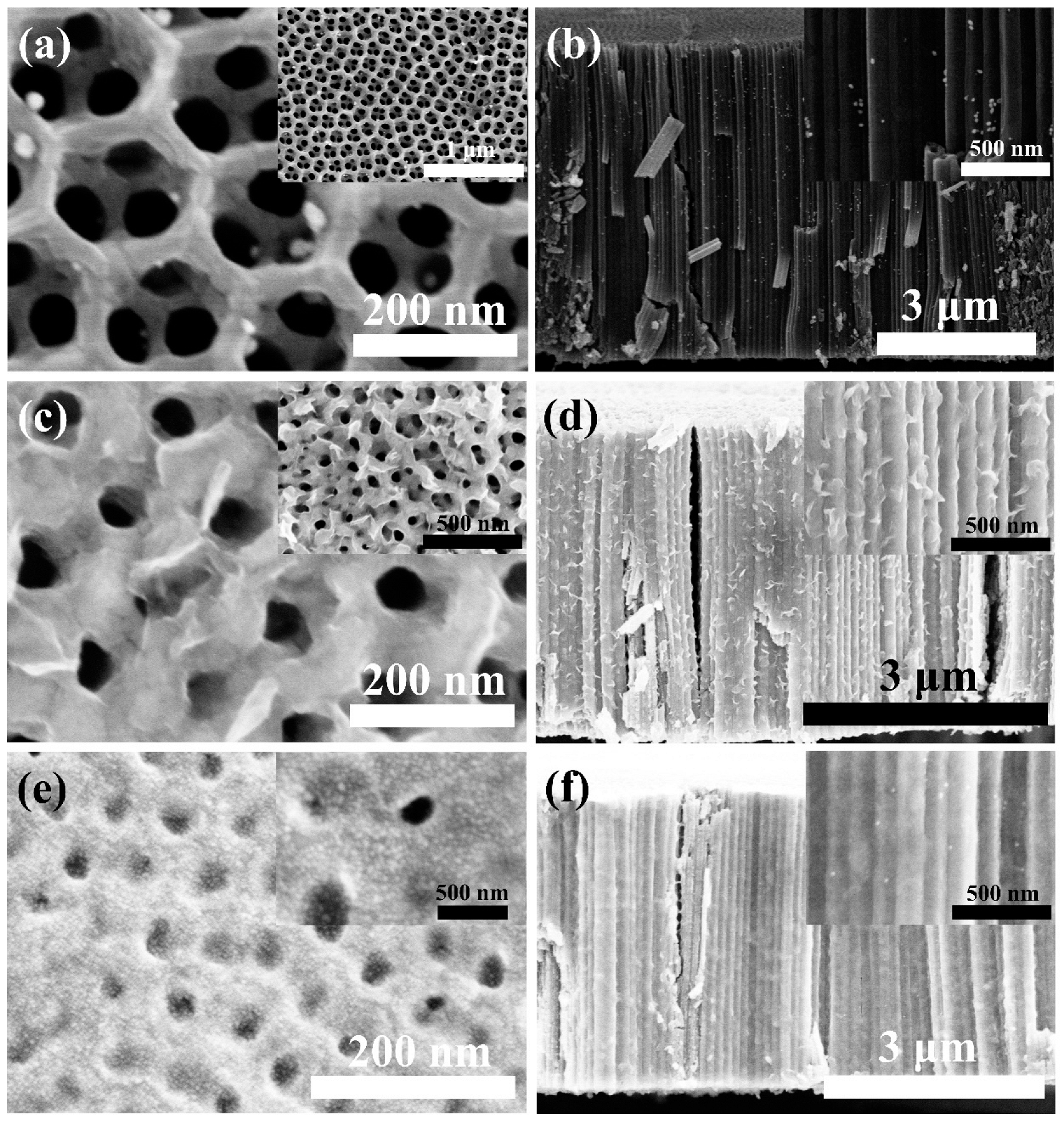
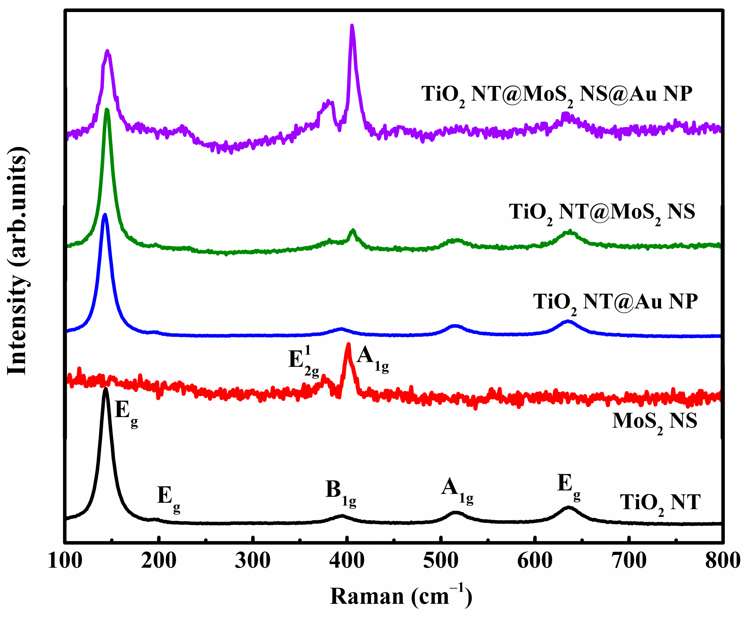
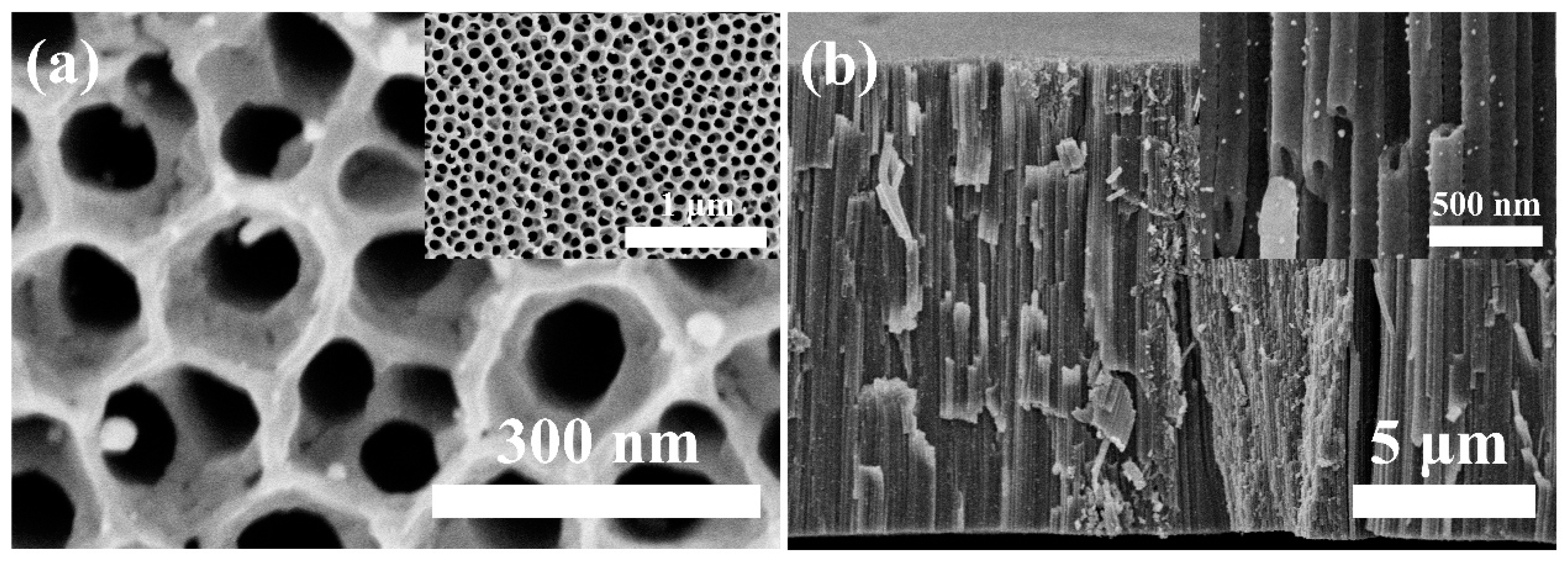
3.1. Materials Characterization

The morphology of the as-annealed secondary oxidized TiO2 nanotube (TiO2 NT) is shown in Figure S1. Typically, a regular network structure is formed on the top of the TiO2 nanotube, resulting in its large specific surface area [25]. The top of the TiO2 NT array has a double-layer honeycomb structure, which is conducive to photocatalysis and energy storage [25,26,27]. Therefore, we use the secondary oxidized TiO2 nanotube (TiO2 NT) as a matrix to prepare high-performance catalyst and lithium battery anode. Figure 1a,b shows the SEM images of the TiO2 nanotube@Au nanoparticle (TiO2 NT@Au NP) composite. The length of the TiO2 NTs is around 6 μm, the inner diameter is around 50 nanometers, and the outer diameter is around 140 nm. In addition, the size of Au nanoparticles is between 10 and 25 nm. Au nanoparticles are evenly distributed on the top and outer wall of the TiO2 NTs (Figure S2).
The presence of PVP (as a surfactant) is an important factor for the successful preparation of TiO2 nanotube@MoS2 nanosheet (TiO2 NT@MoS2 NS) composites. When the surfactant is not present, the MoS2 nanosheet cannot be coated on the TiO2 nanotube (Figure S3a,b). With the increase in the mass of the surfactant, the MoS2 NS coating of the TiO2 NT is gradually perfect (Figure S3c–f and Figure 1c,d). While the mass of PVP is 0.5 g, the MoS2 NS is well coated on the TiO2 NT to form a perfect TiO2 NT@MoS2 NS composite. Furthermore, the TiO2 nanotube@MoS2 nanosheet@Au nanoparticle (TiO2 NT@MoS2 NS@Au NP) composites were also successfully prepared; as shown in Figure 1e,f, the TiO2 NT@MoS2 NS composites were modified by Au nanoparticles. Thanks to the simultaneous appearance of MoS2 nanosheets and Au nanoparticles, the TiO2 NT@MoS2 NS@Au NP composite has improved lithium capacity and excellent conductivity, which will be shown in the following section.
The structure information of various samples was detected by Raman (Figure 2). The Raman spectrum of TiO2 NT shows five peaks, corresponding to Eg, Eg, B1g, A1g, and Eg vibration modes of anatase TiO2, which is consistent with the literature [28,29,30]. Additionally, the anatase crystal structure of the TiO2 nanotube was further confirmed by XRD [31,32,33] and TEM [28,33,34] results (Figure S4). The Raman spectra of TiO2 NT@Au NP composite are similar to that of the pristine TiO2 NT, because Au (as a metal material) does not show Raman vibration peak. MoS2 nanosheet powder’s Raman spectrum shows two peaks at around 379 and 405 cm−1, matching the E 2 g 1 (in-plane) and A1g (out-of-plane) vibration modes, respectively [35]. The peak position difference of E 2 g 1 and A1g vibration modes (Δω) is related to the number of layers of MoS2. As the number of layers of MoS2 changes from monolayer to bulk phase, the value of Δω increases from 19.57 to 25.5 cm−1 [36]. The frequency difference Δω between E 2 g 1 and A1g vibration modes of MoS2 powder (Figure S5) is 26 cm−1, indicating that MoS2 powder is a bulk material [35]. The Raman spectrum of TiO2 NT@MoS2 NS composite not only contains the typical vibration modes of anatase TiO2, but also contains the E 2 g 1 and A1g vibration modes of MoS2. Particularly, the Δω of MoS2 coating is 24, in TiO2 NT@MoS2 NS composite, indicating that the coating is four-layer MoS2 [37]. The transition of MoS2 from bulk phase of MoS2 powder to four layers of MoS2 coating may be due to the gap between TiO2 NTs limiting the accumulation of MoS2, resulting in the formation of four-layer MoS2. Similarly, the MoS2 coating in the TiO2 NT@MoS2 NS@Au NP composite is also four-layer MoS2. Combined with SEM and Raman results, it can be seen that the TiO2 NT@Au NP, TiO2 NT@MoS2 NS, and TiO2 NT@MoS2 NS@Au NP composites were successfully prepared.

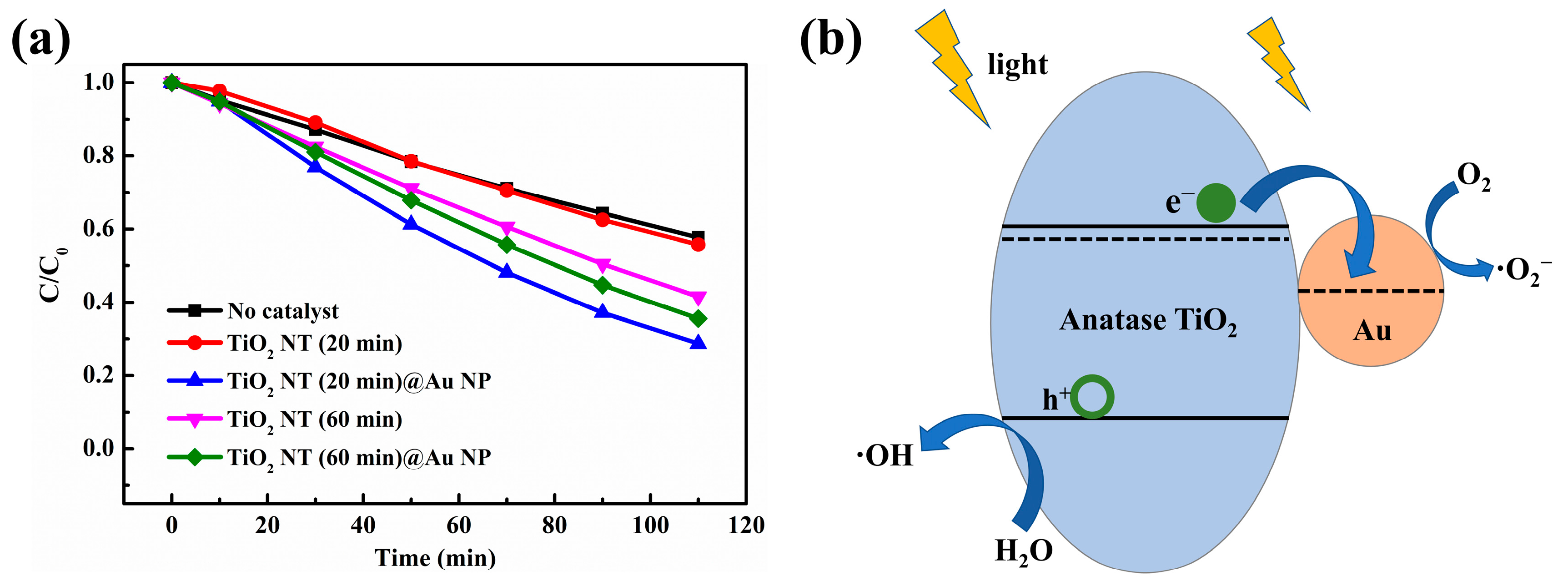
3.2. Photocatalytic Properties of TiO2 NT@Au NP Composites

In order to measure the photocatalytic activities of TiO2 NT@Au NP composites with a nanotube oxidation time of 20 min (TiO2 NT (20 min)@Au NP), the experiment of photocatalytic degradation of methylene blue (MB) was carried out. For comparison, TiO2 nanotubes with a secondary oxidation time of 60 min were also used as substrates to successfully prepare TiO2 NT (60 min)@Au NP composites, which was also used as a catalyst for degradation of MB. The TiO2 NT (60 min) also has a self-organized tube morphology similar to the TiO2 NT (20 min) (Figure 1a,b), and the Au particles are evenly anchored on the top and outside of the TiO2 NT (60 min) in TiO2 NT (60 min)@Au NP composite (Figure 3). Unlike the TiO2 NT (20 min)@Au NP composites, in TiO2 NT (60 min)@Au NP composites, the length of the nanotubes is 13 μm and the double-layer honeycomb structure on the top of the nanotubes becomes thinner. The thinning of the double-layer honeycomb structure is mainly due to the corrosion of the double-layer honeycomb structure after long-term (60 min) exposure to the electrolyte (containing F) during secondary oxidation process [2,38]. In addition, compared with the TiO2 NT (20 min)@Au NP composite, the TiO2 NT (60 min)@Au NP composite has more Au particles anchored on the nanotubes, which may be due to more defects on the TiO2 nanotubes (60 min) providing more binding sites for the growth of Au nanoparticles [30,39]. The extra defects in TiO2 NTs (60 min) are also caused by long-term exposure of NTs to corrosive electrolyte (containing F) [2,38].
Figure 4a shows the degradation curve of MB using different samples as catalysts under UV-visible light irradiation. There was no catalyst in the control experiment, and only UV-visible light irradiation was carried out. The control experiment exhibits only a small amount of degradation of MB, which may be due to thermal degradation caused by UV-visible light irradiation. The TiO2 NT (20 min) shows no photocatalytic effect, due to the high electron-hole pair recombination rate. Compared with TiO2 NT (20 min), the catalytic effect of TiO2 NT (60 min) is improved due to the increase in the amount of catalyst and defects. Abundant defects may induce the generation of defect energy levels in the TiO2’s band gap. The appearance of defect energy level increases the diffusion length of carriers, prolongs the life of carriers, hinders the recombination of electron/hole, improves the utilization of light, and increases the catalytic effect [40]. The presence of Au particles acted as separation centers in the TiO2 NT (20 min)@Au NP composite, which reduces the chance of electron-hole pair recombination [11], thus enhancing the photocatalytic effect. Therefore, the TiO2 NT (20 min)@Au NP composite has remarkable photocatalytic properties (Figure 4). Previous studies showed that the photocatalytic properties of the TiO2 matrix composites loaded with Au particles are related to the size [11,41,42] and the density [41,43,44] of Au particles. When the size of nanoparticles is smaller than 5 nm, the catalytic effect of TiO2 matrix composites is more effective [41,43,44]. While the content of Au is 2%, TiO2 matrix composite has the optimal photocatalytic performance [11,41,42]; meanwhile, if the Au content is too large, it will be harmful to the photocatalytic effect [11,41]. Particularly, Figure 4 exhibits that although the TiO2 NT (60 min) shows higher photocatalysis activity than the TiO2 NT (20 min), the photocatalysis activity of TiO2 NT (60 min)@Au NP composite is worse than that of the TiO2 NT (20 min)@Au NP. In TiO2 NT (20 min)@Au NP and TiO2 NT (60 min)@Au NP composites, the size of Au particles is similar, but the content of Au is significantly different (Figure 1a,b and Figure 3). The poorer photocatalytic activity of TiO2 NT (60 min)@Au NP is mainly due to excessive Au content. When the Au content exceeds the optimum, the Au particles act as the recombination center of the electron-hole pair, which impairs the catalytic effect [11,41].
The schematic diagram of the photocatalytic degradation of MB by TiO2 NT (20 min)@Au NP composites is illustrated in Figure 4b. Titanium oxide (TiO2 NT), as an n-type semiconductor material, has a work function of 4.2 eV and a band gap of 3.2 eV [45,46], and gold has a work function of 5.0 eV [47]. Thus, a Schottky junction is formed at the Au NP/TiO2 NT interface, because the gold’s work function is larger than that of n-type TiO2. The appearance of Schottky junction increases the separation of electron-hole pairs and improves the photocatalysis degradation activity of TiO2 nanotube [11,42]. Specifically, under the irradiation of UV-visible light, the electrons in TiO2 NT are excited to the conduction band from the valence band, while leaving holes with positive charges in the valence band (Figure 4b). These photogenerated electrons are transferred to Au particles, activating the adsorbed oxygen molecules (O2) into superoxide radicals (·O2) [11,47]. Holes are left on the valence band of TiO2 NT for the surface oxidation reaction to generate hydroxyl radicals (·OH) [12]. Finally, the ·O2 and ·OH can react with MB to produce inorganic substance (e.g., CO2 and H2O) [48]. Herein, the high electron separation and transfer ability at the TiO2/Au interface inhibits the high electron-hole recombination of TiO2 NT (20 min), which explains the improvement of the photocatalysis efficiency of the TiO2 NT (20 min)@Au NP composites. However, the content of gold is too large in the TiO2 NT (60 min)@Au NP composite, thus the Au particles with a lot of negative charges become the hole capture center, increasing the electron-hole recombination, and damaging the photocatalytic efficiency [11,42,49]. So far, the TiO2 NT (20 min)@Au NP composite shows excellent photocatalytic properties because of its large specific surface area and appropriate Au content, and this material with enhanced conductivity will also show good application potential in lithium ion energy storage.

3.3. Electrochemical Measurements

Anatase TiO2 nanotube with a duration of 20 min of secondary anodic oxidation (named TiO2 NT) was selected as the matrix for the preparation of composite anodes for lithium battery, due to the perfect double-layer honeycomb surface and large specific surface area of the nanotubes. The conductivity of the TiO2 NT@Au NP composite is analyzed and predicted by the energy band diagram shown in Figure 5. The Schottky junction was formed in the TiO2 NT@Au NP composite (Figure 5b), and the Schottky barrier is 1.0 eV (eϕBn = 1.0 eV), and the built-in electric field barrier is 0.8 eV (eVbi = 0.8 eV). When we apply a positive voltage to TiO2 relative to gold (Figure 5c), the Schottky junction is reverse biased. A large number of electrons can easily cross the Schottky barrier from Au to TiO2, because the Schottky barrier (eϕBn) remains unchanged. Meanwhile, if we apply a positive voltage to gold relative to TiO2 (Figure 5d), the TiO2 NT/Au NP junction is forward biased. In the case of positive bias of Schottky junction, the electrons can easily pass through the entire TiO2 NT@Au NP composite by overcoming a reduced potential barrier e(Vbi − V) (Figure 5d). The TiO2 NT@Au NP composite exhibits good electron flow characteristics in two kinds of electric fields with opposite directions (responding to charging/discharging electric field of lithium battery), which reveals that the appearance of Schottky junction improves the conductivity of TiO2 nanotubes. Enhanced conductivity will improve the electrochemical performance of TiO2 NT@Au NP anode, which will be revealed in the subsequent electrochemical analysis.
The energy band diagram of TiO2 NT@MoS2 NS and TiO2 NT@MoS2 NS@Au NP heterojunctions is shown in Figure S6. Figure S6a shows the energy band diagrams of anatase TiO2 NT, MoS2 NS [50,51,52,53], and Au NP before contact. The nn isotype heterojunction was formed in the TiO2 NT@MoS2 NS composite (Figure S6b). If a reverse-biased voltage (V, positive voltage to TiO2 relative to MoS2) is applied across the heterojunction, the built-in electric field barrier eVbi increases to e(Vbi + V) (Figure S6c). Similarly, if a forward bias is applied, the eVbi is reduced to e(Vbi − V). Under the presence of nn isotype heterojunction, electrons can easily flow through the entire composite material in the opposite electric field direction (responding to charging/discharging electric field of lithium battery), as shown in Figure S6c,d. Figure S6e shows the energy band diagram of TiO2 NT@MoS2 NS@Au NP heterojunction accompanied by the anatase TiO2/MoS2 interface (nn isotype heterojunction) and the MoS2/Au interface (Schottky heterojunction). Based on the above analysis of Schottky and nn heterojunctions, electrons also can easily flow through the entire TiO2 NT@MoS2 NS@Au NP electrode in charge/discharge electric fields, resulting in good conductivity of the electrode. Therefore, all as-prepared composites have enhanced electrical conductivity, which is conducive to improving the electrochemical performance of them.
Galvanostatic charge–discharge curves of the as-prepared anodes are displayed in Figure 6. TiO2 NT has a typical charging/discharging voltage plateau at 2.0/1.7 V (Figure 6a), which corresponds to the lithium extraction from and insertion into the anatase phase TiO2, respectively [54,55]. The initial discharge capacity and initial coulomb efficiency of the TiO2 NT are 188.5 μAh cm−2 and 60.0% (Table 1). Figure 6b demonstrates the charge–discharge curves of the TiO2 NT@Au NP composite anode, obviously, the initial discharge capacity (310.6 μAh cm−2, 1.6 times of the pristine TiO2 NT) and initial coulomb efficiency (76.5%) of the composite were more significantly improved than pristine TiO2 NT. Au particles can store lithium-ion in the form of alloy [55]. The modification of Au particles not only improves the lithium storage capacity of NTs, but also markedly improves the conductivity of TiO2 NTs (Figure 5) enhancing electrochemical lithium storage performance. The TiO2 NT@MoS2 NS composite anode exhibits an initial discharge capacity of 391.3 μAh cm−2 and an initial coulomb efficiency of 51.0% (Table 1). Due to the introduction of MoS2, the capacity of the TiO2 NT@MoS2 NS composite was significantly improved (2.1 times the capacity of the pristine TiO2 NT), and the charge/discharge voltage plateaus moved to 2.1/1.65 V [53]. Because the TiO2 NT@MoS2 NS composite underwent 450 ℃ high-temperature annealing in argon atmosphere, there are abundant defects in the nanotubes of the composite anode, so the charge–discharge curve is more inclined with smaller voltage plateaus, indicating a more amorphous crystal structure and a more uniform lithium intercalation process [54,56,57]. Due to the introduction of defects, the conductivity of TiO2 NT@MoS2 NS was also improved, which is conducive to the improvement of its electrochemical performance [28,58]. However, the low initial coulomb efficiency (51.0%) of the TiO2 NT@MoS2 NS corresponds to a large irreversible capacity, which is mainly caused by the irreversible lithium insertion of MoS2 [59,60]. To further enhance the electrochemical properties of the TiO2 NT@MoS2 NS, we modified the TiO2 NT@MoS2 NS composite with Au nanoparticles. The TiO2 NT@MoS2 NS@ Au NP composite contains not only MoS2 with high capacity, but also Au particles with high conductivity, so the composite material has large initial discharge-specific capacity (487.4 μAh cm−2) and high initial coulomb efficiency (65.8%).
Figure 7a shows the third scan cycle CV curves of four different samples under a scanning rate of 0.1 mV/s. Obviously, the electrochemical behaviors of the samples revealed by CV curves is similar to that revealed by the galvanostatic charge–discharge curves (Figure 6). A pair of obvious redox peaks (around 2.5/1.3 V) responds to the process of lithium extraction from and insertion into anatase TiO2 [22,54]. Consistent with the literature, the addition of gold does not cause additional peaks in the CV curves [61,62]. In addition, there is no typical peak of MoS2 because of the low content of molybdenum sulfide in the composites [22], as well as the overlap of the peak positions of MoS2 and TiO2 [22,30,53,60] forming broad peaks. In particular, the anodic peak and cathodic peak of the TiO2 NT@MoS2 NS composite moved to 2.7 and 1.2 V, respectively, corresponding to the shift of the voltage plateaus in the galvanostatic charge–discharge curve (Figure 6c). Such a shift in these peak positions is mainly due to the introduction of molybdenum sulfide in the TiO2 NT@MoS2 NS composite anode [53]. Another point to note is that the area of CV curves is proportional to the lithium storage capacity of composite anodes. The value of the CV area of the as-prepared samples has the same order as the value of the specific capacity revealed by the galvanostatic charge–discharge curves (TiO2 NT < TiO2 NT@MoS2 NS < TiO2 NT@Au NP < TiO2 NT@MoS2 NS@Au NP).
Cyclic stability is an important part of the performance of lithium batteries in practical applications. The cyclic stability of the TiO2 NT@MoS2 NS@Au NP anode is shown in Figure 7b. The well-designed TiO2 NT@MoS2 NS@Au NP anode shows the highest specific capacity; even after 50 cycles, it still has a specific capacity of up to 273.6 μAh cm−2. After 50 cycles, TiO2 NT@MoS2 NS@ Au NP has a capacity retention rate of 81.0% (compared with the second discharge capacity), which is higher than that of TiO2 NT@Au NP (67.8%) and TiO2 NT@MoS2 NS (74.8%) anodes (Table 1). The high capacity and excellent stability of the TiO2 NT@MoS2 NS@Au NP composite are mainly attributed to several factors. First, the small volume expansion coefficient of the TiO2 NT matrix during the charge–discharge cycle leads to excellent cycle stability. Second, the high theoretical specific capacity of MoS2 improves the capacity of the composite. Third, the introduction of defects and Au particles makes TiO2 NT@MoS2 NS@Au NP have excellent electronic/ion conductivity. The as-designed TiO2 NT@MoS2 NS@Au NP electrode will show great potential in practical applications of the lithium-ion battery, and the design concept of the composite also has an important inspiration for the design of other ideal lithium-ion battery anode.
The button batteries were disassembled in glove box after 50 lithiation/delithiation cycles. SEM images of cycled anode materials are shown in Figure S7. The TiO2 nanotube anode maintains the best tubular morphology (Figure S7a–c), without significant expansion and breakage [2,17], corresponding to the highest cycle stability (Table 1). In TiO2 NT@Au NP composite, Au particles fall off and agglomerate during the cycling process, resulting in a significant capacity degeneration with the lowest capacity retention (Table 1). Due to the inherent low structural strength of MoS2 [17,59], TiO2 NT@MoS2 NS composite’s morphology underwent significant changes, accompanied by the crushing of MoS2 nanosheets and the fracture of TiO2 nanotubes (Figure S7g–i). In the TiO2 NT@MoS2 NS@Au NP composite, the collapse of the thin MoS2 NS coating is mitigated by highly stable TiO2 nanotubes [17], so the MoS2 NS in the composite is not subject to pulverization. In addition, the presence of MoS2 nanosheets stabilizes the attachment of gold nanoparticles, and the gold particles do not fall off after cycling. Therefore, TiO2 NT@MoS2 NS@Au NP composite has improved cycle stability compared to TiO2 NT@Au NP and TiO2 NT@MoS2 NS composites (Table 1).

4. Conclusions

The carefully designed ternary TiO2 nanotube@MoS2 nanosheet@Au nanoparticle (TiO2 NT@MoS2 NS@Au NP) composite with excellent electrochemical performance was successfully prepared via combining two-step electrochemical anodization and the hydrothermal method. The TiO2 NT@MoS2 NS@Au NP anode with abundant defects and highly ordered arrangement demonstrates outstanding structural stability after charge/discharge cycles. Therefore, the TiO2 NT@MoS2 NS@Au NP anode exhibits not only high discharge capacity (487.4 μAh cm−2), but also excellent capacity stability (a capacity retention rate of 81.0%, after 50 cycles). In addition, as a multifunctional material, the TiO2 nanotube@Au nanoparticle (TiO2 NT@Au NP) composite showed excellent photocatalytic degradation performance and enhanced electrochemical performance. The excellent performances of multi-functional TiO2 NT@Au NP composites can be attributed to following accounts: (1) the double-layer honeycomb surface structure of TiO2 NT matrix makes the composite have a large surface area. (2) The appropriate concentration of gold as the separation center reduces the recombination of electron-hole pairs. (3) The excellent conductivity of Au/TiO2 NT Schottky junction improves the electron and ion transport efficiency. Therefore, TiO2 NT matrix composites, including TiO2 NT@Au NP, TiO2 NT@MoS2 NS, and TiO2 NT@MoS2 NS@Au NP, exhibit excellent potential in photocatalysis and lithium storage, which will open a new avenue for pollutant degradation and energy storage.

Supplementary Materials

The following supporting information can be downloaded at: https://www.mdpi.com/article/10.3390/ma16072716/s1, Figure S1: (a) Low magnification and (b) high magnification SEM images of as-annealed secondary oxidized TiO2 nanotube (TiO2 NT); Figure S2: SEM images of the (a) top, (b,c) middle, and (d) bottom parts of the TiO2 NT@Au NP composite; Figure S3: When the surfactant (PVP) is not present, the MoS2 nanosheet cannot be coated on the TiO2 nanotube, and (a,b) is the corresponding SEM images. SEM images of TiO2 nanotube@MoS2 nanosheet composites when the mass of PVP surfactant is (c,d) 0.1 g (TiO2 NT@MoS2 NS, 0.1 g) and (e,f) 0.3 g (TiO2 NT@MoS2 NS, 0.3 g); Figure S4: (a) XRD of TiO2 nanotube, as well as (b) TEM and (c) HRTEM images of TiO2 nanotube; Figure S5: (a) High magnification and (b) low magnification SEM images of MoS2 powder; Figure S6: (a) Energy-band diagrams of TiO2 nanotube, MoS2 nanosheet and Au nanoparticle. (b–d) Energy-band diagrams of TiO2 nanotube@MoS2 nanosheet composite. (e) Energy-band diagrams of TiO2 nanotube@MoS2 nanosheet@ Au nanoparticle composite; Figure S7: SEM images of four different anode materials, after 50 cycles, at 100 μA cm−2. SEM images of cycled (a–c) TiO2 nanotube anode, (d–f) TiO2 nanotube@Au nanoparticle anode, (g–i) TiO2 nanotube@MoS2 nanosheet anode and (j–l) TiO2 nanotube@MoS2 nanosheet@ Au nanoparticle anode.

Author Contributions

Writing—original draft preparation, M.Z.; writing—review and editing, H.L. and C.W. All authors have read and agreed to the published version of the manuscript.

Funding

This work is supported by the National Natural Science Foundation of China (No. 61376017, 12004070); the Fundamental Research Funds for the Central Universities and Graduate Student Innovation Fund of Donghua University (No. BCZD2021007&CUSF-DH-D-2020094).

Institutional Review Board Statement

Not applicable.

Informed Consent Statement

Not applicable.

Data Availability Statement

The data presented in this work are available from the corresponding authors upon request.

Conflicts of Interest

The authors declare no conflict of interest.

References

  1. Li, H.; Chen, Z.; Tsang, C.K.; Li, Z.; Ran, X.; Lee, C.; Nie, B.; Zheng, L.; Hung, T.; Lu, J.; et al. Electrochemical doping of anatase TiO2 in organic electrolytes for high-performance supercapacitors and photocatalysts. J. Mater. Chem. A 2014, 2, 229–236. [Google Scholar] [CrossRef]
  2. Zhang, M.M.; Wang, C.R.; Li, H.; Wang, J.L.; Li, M.; Chen, X.S. Enhanced performance of lithium ion batteries from self-doped TiO2 nanotube anodes via an adjustable electrochemical process. Electrochim. Acta 2019, 326, 134972. [Google Scholar] [CrossRef]
  3. Zhang, M.M.; Chen, J.Y.; Li, H.; Wang, C.R. Recent progress in Li-ion batteries with TiO2 nanotube anodes grown by electrochemical anodization. Rare Met. 2021, 40, 249–271. [Google Scholar]
  4. Duan, J.; Hou, H.; Liu, X.; Yan, C.; Liu, S.; Meng, R.; Hao, Z.; Yao, Y.; Liao, Q. In situ Ti3+-doped TiO2 nanotubes anode for lithium ion battery. J. Porous Mater. 2016, 23, 837–843. [Google Scholar] [CrossRef]
  5. Myung, S.T.; Kikuchi, M.; Yoon, C.S.; Yashiro, H.; Kim, S.J.; Sun, Y.K.; Scrosati, B. Black anatase titania enabling ultra high cycling rates for rechargeable lithium batteries. Energy Environ. Sci. 2013, 6, 2609–2614. [Google Scholar] [CrossRef]
  6. He, J.Y.; Chen, T.S. Synthesis of Cross-like TiO2 Thermally Derived from Ammonium Oxofluorotitanate Mesocrystals Under Different Calcination Temperatures and Their Photocatalytic Activity. Electron. Mater. Lett. 2023, 19, 84–93. [Google Scholar] [CrossRef]
  7. Puga, M.L.; Venturini, J.; ten Caten, C.S.; Bergmann, C.P. Influencing parameters in the electrochemical anodization of TiO2 nanotubes: Systematic review and meta-analysis. Ceram. Int. 2022, 48, 19513–19526. [Google Scholar] [CrossRef]
  8. Yi, T.F.; Fang, Z.K.; Xie, Y.; Zhu, Y.R.; Yang, S.Y. Rapid Charge-Discharge Property of Li4Ti5O12-TiO2 Nanosheet and Nanotube Composites as Anode Material for Power Lithium-Ion Batteries. ACS Appl. Mater. Interfaces 2014, 6, 20205–20213. [Google Scholar] [CrossRef]
  9. Li, X.Y.; Chen, Y.M.; Zhou, L.M.; Mai, Y.W.; Huang, H.T. Exceptional electrochemical performance of porous TiO2-carbon nanofibers for lithium ion battery anodes. J. Mater. Chem. A 2014, 2, 3875–3880. [Google Scholar] [CrossRef]
  10. Zhang, Y.Y.; Li, J.; Li, W.Y.; Kang, D.N. Synthesis of One-Dimensional Mesoporous Ag Nanoparticles-Modified TiO2 Nanofibers by Electrospinning for Lithium Ion Batteries. Materials 2019, 12, 2630. [Google Scholar] [CrossRef] [Green Version]
  11. Li, X.H.; Chen, G.Y.; Yang, L.B.; Jin, Z.; Liu, J.H. Multifunctional Au-Coated TiO2 Nanotube Arrays as Recyclable SERS Substrates for Multifold Organic Pollutants Detection. Adv. Funct. Mater. 2010, 20, 2815–2824. [Google Scholar] [CrossRef]
  12. Zhang, X.D.; Yue, D.; Zhang, L.; Lin, S.W. Three-dimensional flexible Au nanoparticles-decorated TiO2 nanotube arrays for photoelectrochemical biosensing. J. Mater. Sci. Technol. 2020, 56, 162–169. [Google Scholar] [CrossRef]
  13. He, F.; Meng, A.Y.; Cheng, B.; Ho, W.K.; Yu, J.G. Enhanced photocatalytic H2-production activity of WO3/TiO2 step-scheme heterojunction by graphene modification. Chin. J. Catal. 2020, 41, 9–20. [Google Scholar] [CrossRef]
  14. Wu, X.D.; Wang, Z.X.; Chen, L.Q.; Huang, X.J. Ag-enhanced SEI formation on Si particles for lithium batteries. Electrochem. Commun. 2003, 5, 935–939. [Google Scholar] [CrossRef]
  15. Kwon, E.; Lim, H.S.; Sun, Y.K.; Suh, K.D. Improved rate capability of lithium-ion batteries with Ag nanoparticles deposited onto silicon/carbon composite microspheres as an anode material. Solid State Ion. 2013, 237, 28–33. [Google Scholar] [CrossRef]
  16. Rahman, M.M.; Wang, J.Z.; Wexler, D.; Zhang, Y.Y.; Li, X.J.; Chou, S.L.; Liu, H.K. Silver-coated TiO2 nanostructured anode materials for lithium ion batteries. J. Solid State Electrochem. 2010, 14, 571–578. [Google Scholar] [CrossRef] [Green Version]
  17. Wang, H.Y.; Jiang, H.; Hu, Y.J.; Deng, Z.N.; Li, C.Z. Interface engineering of few-layered MoS2 nanosheets with ultrafine TiO2 nanoparticles for ultrastable Li-ion batteries. Chem. Eng. J. 2018, 345, 320–326. [Google Scholar] [CrossRef]
  18. Shan, T.T.; Xin, S.; You, Y.; Cong, H.P.; Yu, S.H.; Manthiram, A. Combining Nitrogen-Doped Graphene Sheets and MoS2: A Unique Film-Foam-Film Structure for Enhanced Lithium Storage. Angew. Chem.-Int. Ed. 2016, 55, 12783–12788. [Google Scholar] [CrossRef]
  19. Politano, G.G.; Castriota, M.; De Santo, M.P.; Pipita, M.M.; Desiderio, G.; Vena, C.; Versace, C. Variable angle spectroscopic ellipsometry characterization of spin-coated MoS2 films. Vacuum 2021, 189, 110232. [Google Scholar] [CrossRef]
  20. Liu, Y.P.; He, X.Y.; Hanlon, D.; Harvey, A.; Khan, U.; Li, Y.G.; Coleman, J.N. Electrical, Mechanical, and Capacity Percolation Leads to High-Performance MoS2/Nanotube Composite Lithium Ion Battery Electrodes. ACS Nano 2016, 10, 5980–5990. [Google Scholar] [CrossRef]
  21. Fang, Y.; Lv, Y.Y.; Gong, F.; Elzatahry, A.A.; Zheng, G.F.; Zhao, D.Y. Synthesis of 2D-Mesoporous-Carbon/MoS2 Heterostructures with Well-Defined Interfaces for High-Performance Lithium-Ion Batteries. Adv. Mater. 2016, 28, 9385–9390. [Google Scholar] [CrossRef] [PubMed]
  22. Zhou, H.M.; Lv, P.F.; Xia, X.; Zhang, J.; Yu, J.; Pang, Z.Y.; Qiao, H.; Wei, Q.F. MoS2 nanograins doped TiO2 nanofibers as intensified anodes for lithium ion batteries. Mater. Lett. 2018, 218, 47–51. [Google Scholar] [CrossRef]
  23. Wu, H.J.; Zhang, Z.H. Photoelectrochemical water splitting and simultaneous photoelectrocatalytic degradation of organic pollutant on highly smooth and ordered TiO2 nanotube arrays. J. Solid State Chem. 2011, 184, 3202–3207. [Google Scholar] [CrossRef]
  24. Wu, H.J.; Zhang, Z.H. High photoelectrochemical water splitting performance on nitrogen doped double-wall TiO2 nanotube array electrodes. Int. J. Hydrogen Energy 2011, 36, 13481–13487. [Google Scholar] [CrossRef]
  25. Zhang, M.M.; Zhou, X.; Wang, C.R.; Chen, Z.H.; Li, H. Evaluation of the Titanium Substrate Effect on the Morphology of Anodic TiO2 Nanotubes. ECS J. Solid State Sci. Technol. 2021, 10, 083008. [Google Scholar] [CrossRef]
  26. Sitler, S.J.; Raja, K.S.; Karmiol, Z.; Chidambaram, D. Self-ordering dual-layered honeycomb nanotubular titania: Enhanced structural stability and energy storage capacity. Appl. Surf. Sci. 2017, 401, 127–141. [Google Scholar] [CrossRef]
  27. Wu, H.J.; Wang, Y.; Ma, Y.; Xiao, T.X.; Yuan, D.D.; Zhang, Z.H. Honeycombed TiO2 nanotube arrays with top-porous/bottom-tubular structures for enhanced photocatalytic activity. Ceram. Int. 2015, 41, 2527–2532. [Google Scholar] [CrossRef]
  28. Fang, Y.Z.; Zhang, Y.Y.; Miao, C.X.; Zhu, K.; Chen, Y.; Du, F.; Yin, J.L.; Ye, K.; Cheng, K.; Yan, J.; et al. MXene-Derived Defect-Rich TiO2@rGO as High-Rate Anodes for Full Na Ion Batteries and Capacitors. Nano-Micro Lett. 2020, 12, 128. [Google Scholar] [CrossRef]
  29. Yang, Y.; Fu, Q.; Zhao, H.P.; Mi, Y.; Li, W.; Dong, Y.L.; Wu, M.H.; Lei, Y. MOF-assisted three-dimensional TiO2@C core/shell nanobelt arrays as superior sodium ion battery anodes. J. Alloys Compd. 2018, 769, 257–263. [Google Scholar] [CrossRef]
  30. Zhang, M.M.; Lu, A.J.; Li, H.; Li, M.; Wang, J.E.; Wang, C.R. Defective TiO2-Supported Dual-Schottky Heterostructure Boosts Fast Reaction Kinetics for High Performance Lithium-Ion Storage. ACS Appl. Energy Mater. 2023, 6, 1781–1798. [Google Scholar] [CrossRef]
  31. Chen, K.; Guo, H.N.; Li, W.Q.; Wang, Y.J. MOF-derived Core-Shell CoP@NC@TiO2 Composite as a High-Performance Anode Material for Li-ion Batteries. Chem.-Asian J. 2021, 16, 322–328. [Google Scholar] [CrossRef]
  32. Liu, Y.; Luo, Y.F.; Elzatahry, A.A.; Luo, W.; Che, R.C.; Fan, J.W.; Lan, K.; Al-Enizi, A.M.; Sun, Z.K.; Li, B.; et al. Mesoporous TiO2 Mesocrystals: Remarkable Defects-Induced Crystallite-Interface Reactivity and Their in Situ Conversion to Single Crystals. ACS Central Sci. 2015, 1, 400–408. [Google Scholar] [CrossRef] [PubMed] [Green Version]
  33. Tan, B.Y.; Zhang, X.H.; Li, Y.J.; Chen, H.; Ye, X.Z.; Wang, Y.; Ye, J.F. Anatase TiO2 Mesocrystals: Green Synthesis, In Situ Conversion to Porous Single Crystals, and Self-Doping Ti3+ for Enhanced Visible Light Driven Photocatalytic Removal of NO. Chem.-Eur. J. 2017, 23, 5478–5487. [Google Scholar] [CrossRef] [PubMed]
  34. Liao, J.Y.; Lei, B.X.; Wang, Y.F.; Liu, J.M.; Su, C.Y.; Kuang, D.B. Hydrothermal Fabrication of Quasi-One-Dimensional Single-Crystalline Anatase TiO2 Nanostructures on FTO Glass and Their Applications in Dye-Sensitized Solar Cells. Chem.-Eur. J. 2011, 17, 1352–1357. [Google Scholar] [CrossRef]
  35. Fu, Y.J.; Wang, C.R.; Wang, L.L.; Peng, X.; Wu, B.H.; Sun, X.Q.; Chen, X.S. Synthesis and electrochemical property of few-layer molybdenum disulfide nanosheets. Jpn. J. Appl. Phys. 2016, 55, 125201. [Google Scholar] [CrossRef]
  36. Lee, C.; Yan, H.; Brus, L.E.; Heinz, T.F.; Hone, J.; Ryu, S. Anomalous Lattice Vibrations of Single- and Few-Layer MoS2. ACS Nano 2010, 4, 2695–2700. [Google Scholar] [CrossRef] [Green Version]
  37. Liang, L.B.; Meunier, V. First-principles Raman spectra of MoS2, WS2 and their heterostructures. Nanoscale 2014, 6, 5394–5401. [Google Scholar] [CrossRef]
  38. Berger, S.; Hahn, R.; Roy, P.; Schmuki, P. Self-organized TiO2 nanotubes: Factors affecting their morphology and properties. Phys. Status Solidi B 2010, 247, 2424–2435. [Google Scholar] [CrossRef]
  39. Hwang, J.; Ejsmont, A.; Freund, R.; Goscianska, J.; Schmidt, B.; Wuttke, S. Controlling the morphology of metal-organic frameworks and porous carbon materials: Metal oxides as primary architecture-directing agents. Chem. Soc. Rev. 2020, 49, 3348–3422. [Google Scholar] [CrossRef]
  40. Shang, F.; Chen, S.; Liang, J.; Liu, C. Preparation and Photocatalytic Properties of ZnO Deposited TiO2 Nanotube Arrays by Anodization. J. Nanosci. Nanotechnol. 2019, 19, 2070–2077. [Google Scholar] [CrossRef]
  41. Cardenas-Lizana, F.; Gomez-Quero, S.; Idriss, H.; Keane, M.A. Gold particle size effects in the gas-phase hydrogenation of m-dinitrobenzene over Au/TiO2. J. Catal. 2009, 268, 223–234. [Google Scholar] [CrossRef]
  42. Yoo, S.J.; Jeon, T.Y.; Lee, K.S.; Park, K.W.; Sung, Y.E. Effects of particle size on surface electronic and electrocatalytic properties of Pt/TiO2 nanocatalysts. Chem. Commun. 2010, 46, 794–796. [Google Scholar] [CrossRef] [PubMed]
  43. Cao, Y.S.; Tan, H.H.; Shi, T.Y.; Tang, T.; Li, J.Q. Preparation of Ag-doped TiO2 nanoparticles for photocatalytic degradation of acetamiprid in water. J. Chem. Technol. Biotechnol. 2008, 83, 546–552. [Google Scholar] [CrossRef]
  44. Sung-Suh, H.M.; Choi, J.R.; Hah, H.J.; Koo, S.M.; Bae, Y.C. Comparison of Ag deposition effects on the photocatalytic activity of nanoparticulate TiO2 under visible and UV light irradiation. J. Photochem. Photobiol. A-Chem. 2004, 163, 37–44. [Google Scholar] [CrossRef]
  45. Swaminathan, J.; Ravichandran, S. Insights into the Electrocatalytic Behavior of Defect-Centered Reduced Titania (TiO1.23). J. Phys. Chem. C 2018, 122, 1670–1680. [Google Scholar] [CrossRef]
  46. Choi, H.; Shin, J.; Shin, C. Impact of Source/Drain Metal Work Function on the Electrical Characteristics of Anatase TiO2-Based Thin Film Transistors. ECS J. Solid State Sci. Technol. 2017, 6, P379–P382. [Google Scholar] [CrossRef]
  47. Zhu, K.; Wang, C.R.; Camargo, P.H.C.; Wang, J.L. Investigating the effect of MnO2 band gap in hybrid MnO2-Au materials over the SPR-mediated activities under visible light. J. Mater. Chem. A 2019, 7, 925–931. [Google Scholar] [CrossRef]
  48. Zheng, L.; Han, S.; Liu, H.; Yu, P.; Fang, X. Hierarchical MoS2 Nanosheet@TiO2 Nanotube Array Composites with Enhanced Photocatalytic and Photocurrent Performances. Small 2016, 12, 1527–1536. [Google Scholar] [CrossRef]
  49. Lin, Y.G.; Hsu, Y.K.; Chen, S.Y.; Lin, Y.K.; Chen, L.C.; Chen, K.H. Nanostructured Zinc Oxide Nanorods with Copper Nanoparticles as a Microreformation Catalyst. Angew. Chem.-Int. Ed. 2009, 48, 7586–7590. [Google Scholar] [CrossRef]
  50. Ho, W.K.; Yu, J.C.; Lin, J.; Yu, J.G.; Li, P.S. Preparation and photocatalytic behavior of MoS2 and WS2 nanocluster sensitized TiO2. Langmuir 2004, 20, 5865–5869. [Google Scholar] [CrossRef]
  51. Liu, Y.; Yu, Y.X.; Zhang, W.D. MoS2/CdS Heterojunction with High Photoelectrochemical Activity for H2 Evolution under Visible Light: The Role of MoS2. J. Phys. Chem. C 2013, 117, 12949–12957. [Google Scholar] [CrossRef]
  52. Scalise, E.; Houssa, M.; Pourtois, G.; Afanas∙ev, V.V.; Stesmans, A. First-principles study of strained 2D MoS2. Physica E 2014, 56, 416–421. [Google Scholar] [CrossRef]
  53. Chen, B.A.; Liu, E.Z.; He, F.; Shi, C.S.; He, C.N.; Li, J.J.; Zhao, N.Q. 2D sandwich-like carbon-coated ultrathin TiO2@defect-rich MoS2 hybrid nanosheets: Synergistic-effect-promoted electrochemical performance for lithium ion batteries. Nano Energy 2016, 26, 541–549. [Google Scholar] [CrossRef]
  54. Ryu, W.-H.; Nam, D.-H.; Ko, Y.-S.; Kim, R.-H.; Kwon, H.-S. Electrochemical performance of a smooth and highly ordered TiO2 nanotube electrode for Li-ion batteries. Electrochim. Acta 2012, 61, 19–24. [Google Scholar] [CrossRef]
  55. Meng, R.; Hou, H.; Liu, X.; Hu, W.; Duan, J.; Liu, S. Reassessment of the roles of Ag in TiO2 nanotubes anode material for lithium ion battery. Ceram. Int. 2015, 41, 9988–9994. [Google Scholar] [CrossRef]
  56. Brumbarov, J.; Vivek, J.P.; Leonardi, S.; Valero-Vidal, C.; Portenkirchner, E.; Kunze-Liebhauser, J. Oxygen deficient, carbon coated self-organized TiO2 nanotubes as anode material for Li-ion intercalation. J. Mater. Chem. A 2015, 3, 16469–16477. [Google Scholar] [CrossRef]
  57. Jiang, Y.; Hall, C.; Burr, P.A.; Song, N.; Lau, D.; Yuwono, J.; Wang, D.W.; Ouyang, Z.; Lennon, A. Fabrication strategies for high-rate TiO2 nanotube anodes for Li ion energy storage. J. Power Sources 2020, 463, 228205. [Google Scholar] [CrossRef]
  58. Zhao, C.Y.; Cai, Y.; Yin, K.L.; Li, H.Z.; Shen, D.; Qin, N.; Lu, Z.G.; Liu, C.P.; Wang, H.E. Carbon-bonded, oxygen-deficient TiO2 nanotubes with hybridized phases for superior Na-ion storage. Chem. Eng. J. 2018, 350, 201–208. [Google Scholar] [CrossRef]
  59. Zeng, S.Z.; Wang, C.R.; Li, H.; Wang, J.L.; Xu, X.F.; Wu, B.H.; He, B. Hydrothermal Synthesis VO2(B) Nanorod/MoS2 Nanosheet Heterostructures for Enhanced Performance Lithium-ion Battery Anodes. Chem. Lett. 2019, 48, 367–370. [Google Scholar] [CrossRef]
  60. Qi, D.M.; Li, S.; Chen, Y.H.; Huang, J.G. A hierarchical carbon@TiO2@MoS2 nanofibrous composite derived from cellulose substance as an anodic material for lithium-ion batteries. J. Alloys Compd. 2017, 728, 506–517. [Google Scholar] [CrossRef]
  61. Ahmad, M.; Shi, Y.Y.; Nisar, A.; Sun, H.Y.; Shen, W.C.; Wei, M.; Zhu, J. Synthesis of hierarchical flower-like ZnO nanostructures and their functionalization by Au nanoparticles for improved photocatalytic and high performance Li-ion battery anodes. J. Mater. Chem. 2011, 21, 7723–7729. [Google Scholar] [CrossRef]
  62. Li, C.C.; Li, Q.H.; Chen, L.B.; Wang, T.H. A Facile Titanium Glycolate Precursor Route to Mesoporous Au/Li4Ti5O12 Spheres for High-Rate Lithium-Ion Batteries. ACS Appl. Mater. Interfaces 2012, 4, 1233–1238. [Google Scholar] [CrossRef] [PubMed]
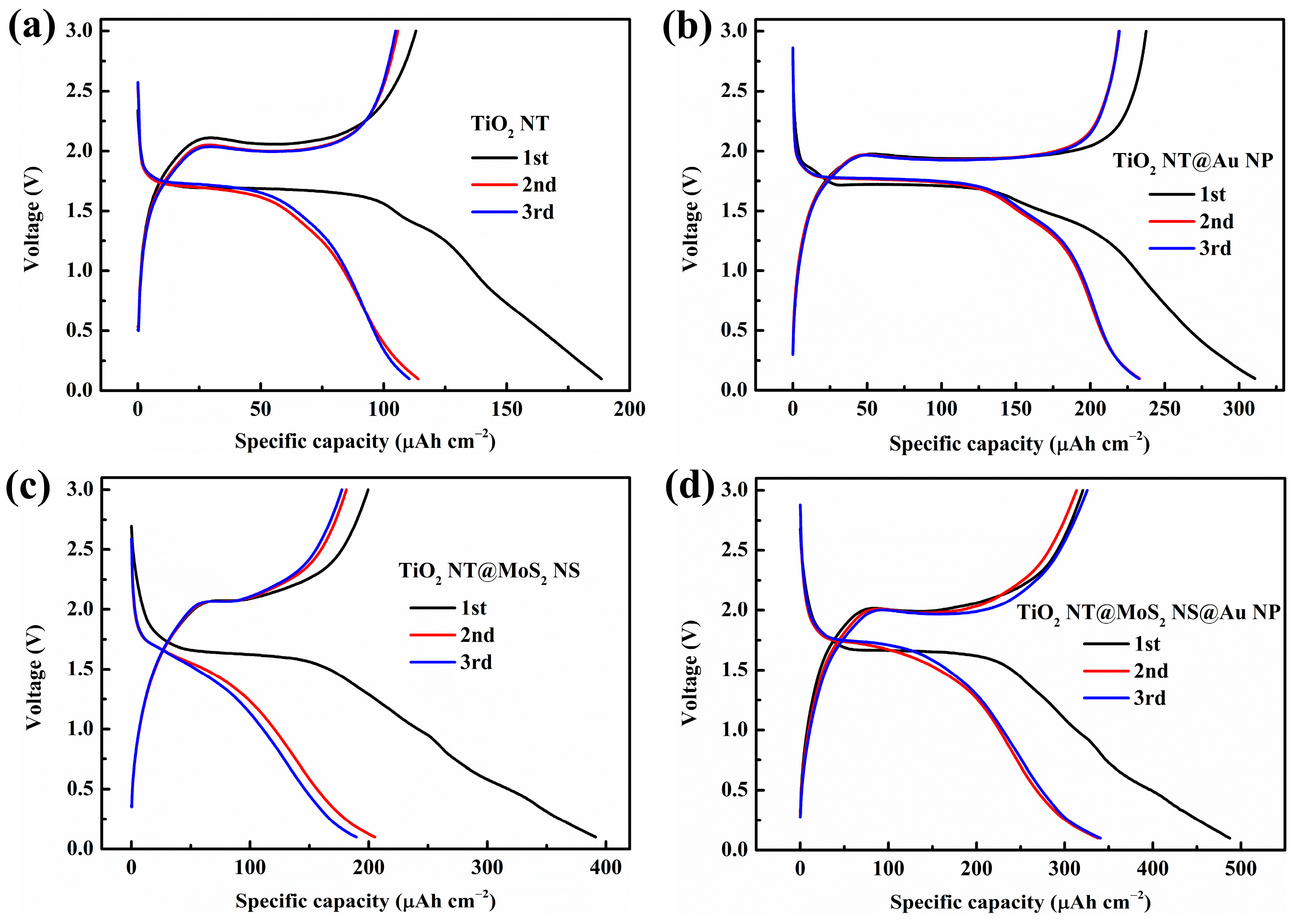
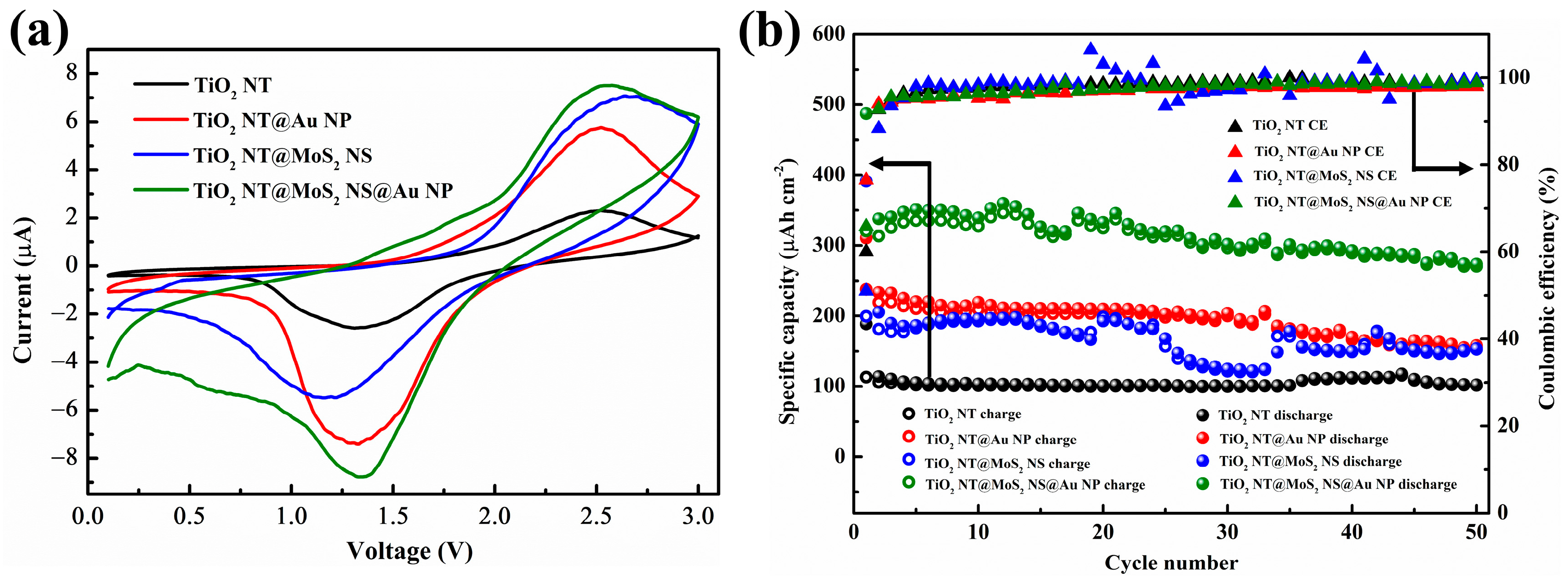
Figure 1. SEM images of (a,b) TiO2 nanotube@Au nanoparticle (TiO2 NT@Au NP) composite, (c,d) TiO2 nanotube@MoS2 nanosheet (TiO2 NT@MoS2 NS, 0.5 g PVP) composite, and (e,f) TiO2 nanotube@MoS2 nanosheet@Au nanoparticle (TiO2 NT@MoS2 NS@Au NP) composite.
Materials 16 02716 g001
Figure 2. Raman spectra of TiO2 NT, MoS2 NS, TiO2 NT@Au NP, TiO2 NT@MoS2 NS, and TiO2 NT@MoS2 NS@Au NP composites.
Materials 16 02716 g002
Figure 3. SEM images of TiO2 NT@Au NP composite with 60 min growth time of TiO2 nanotube. (a) Top view and (b) cross-section view SEM images of the TiO2 NT (60 min)@Au NP composite.
Materials 16 02716 g003
Figure 4. (a) TiO2 NT and TiO2 NT@Au NP composites with different NT growth times (20 min and 60 min), are used as catalysts for photocatalytic degradation of MB. (b) Schematic diagram of photocatalytic degradation of MB by TiO2 NT (20 min)@Au NP composite.
Materials 16 02716 g004
Figure 5. Energy band diagrams for TiO2 NT@Au NP (a) before contact, and (b) after contact for thermal equilibrium. (c) The positive voltage V is applied to the TiO2 NT relative to the Au NP, and (d) the positive voltage V is applied to Au NP relative to the TiO2 NT.
Materials 16 02716 g005
Figure 6. The initial three charge/discharge profiles of (a) TiO2 NT, (b) TiO2 NT@Au NP, (c) TiO2 NT@MoS2 NS, and (d) TiO2 NT@MoS2 NS@Au NP composites, under 100 μA cm−2.
Materials 16 02716 g006
Figure 7. (a) Third cycle CV curves, as well as (b) the cycling stability and coulomb efficiency of TiO2 NT, TiO2 NT@Au NP, TiO2 NT@MoS2 NS, and TiO2 NT@MoS2 NS@Au NP anodes.
Materials 16 02716 g007
Table 1. Initial discharge capacity, initial coulomb efficiency, and capacity retention rate after 50 cycles (compared with the second cycle) of various as-prepared samples.
CapacityInitial Discharge Capacity
(μAh cm−2)
Initial Coulomb Efficiency
(%)
Capacity Retention after 50 Cycles
(%)
Samples
TiO2 NT188.560.089.6
TiO2 NT@Au NP310.676.567.8
TiO2 NT@MoS2 NS391.351.074.8
TiO2 NT@MoS2 NS@Au NP487.465.881.0
Disclaimer/Publisher’s Note: The statements, opinions and data contained in all publications are solely those of the individual author(s) and contributor(s) and not of MDPI and/or the editor(s). MDPI and/or the editor(s) disclaim responsibility for any injury to people or property resulting from any ideas, methods, instructions or products referred to in the content.

