
Bonding Mechanical Properties between SMA Fiber and ECC Matrix under Direct Pullout Loads

Abstract
:1. Introduction
2. Experiment Design
2.1. Materials
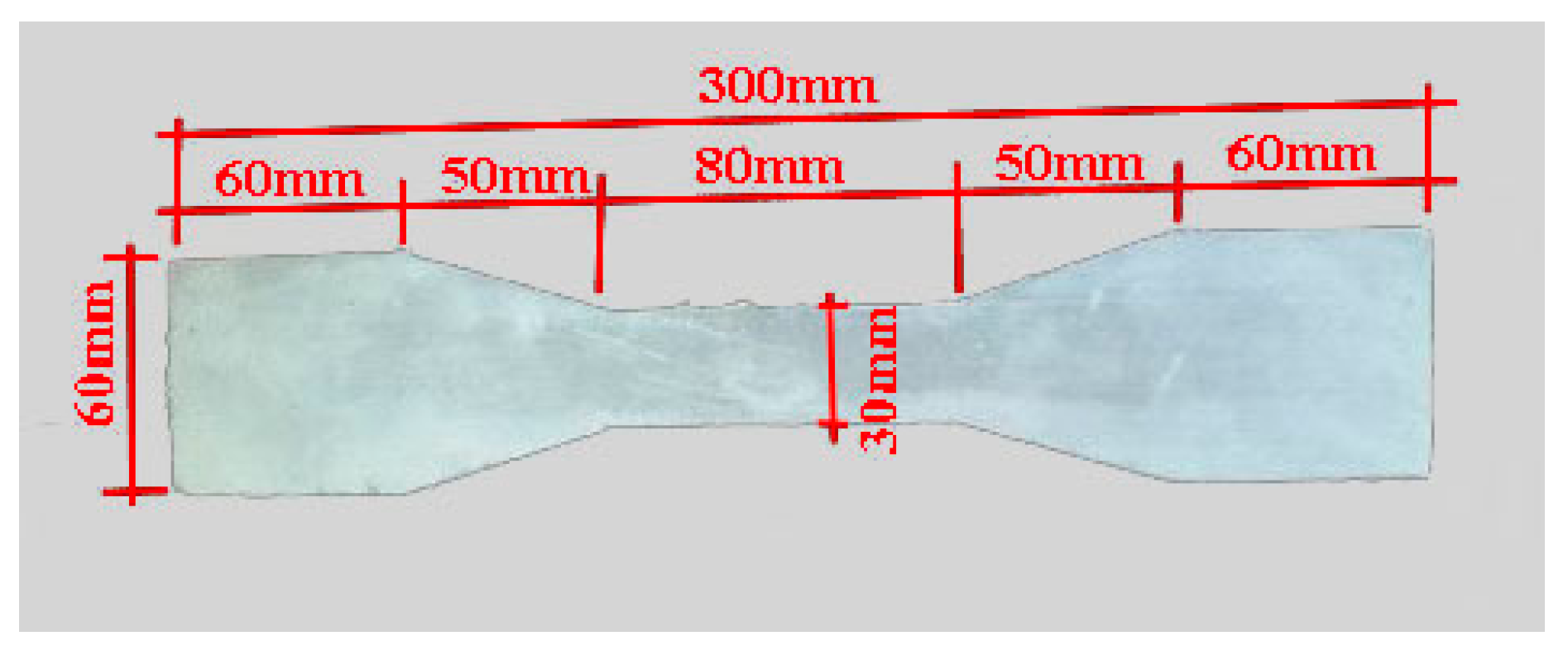
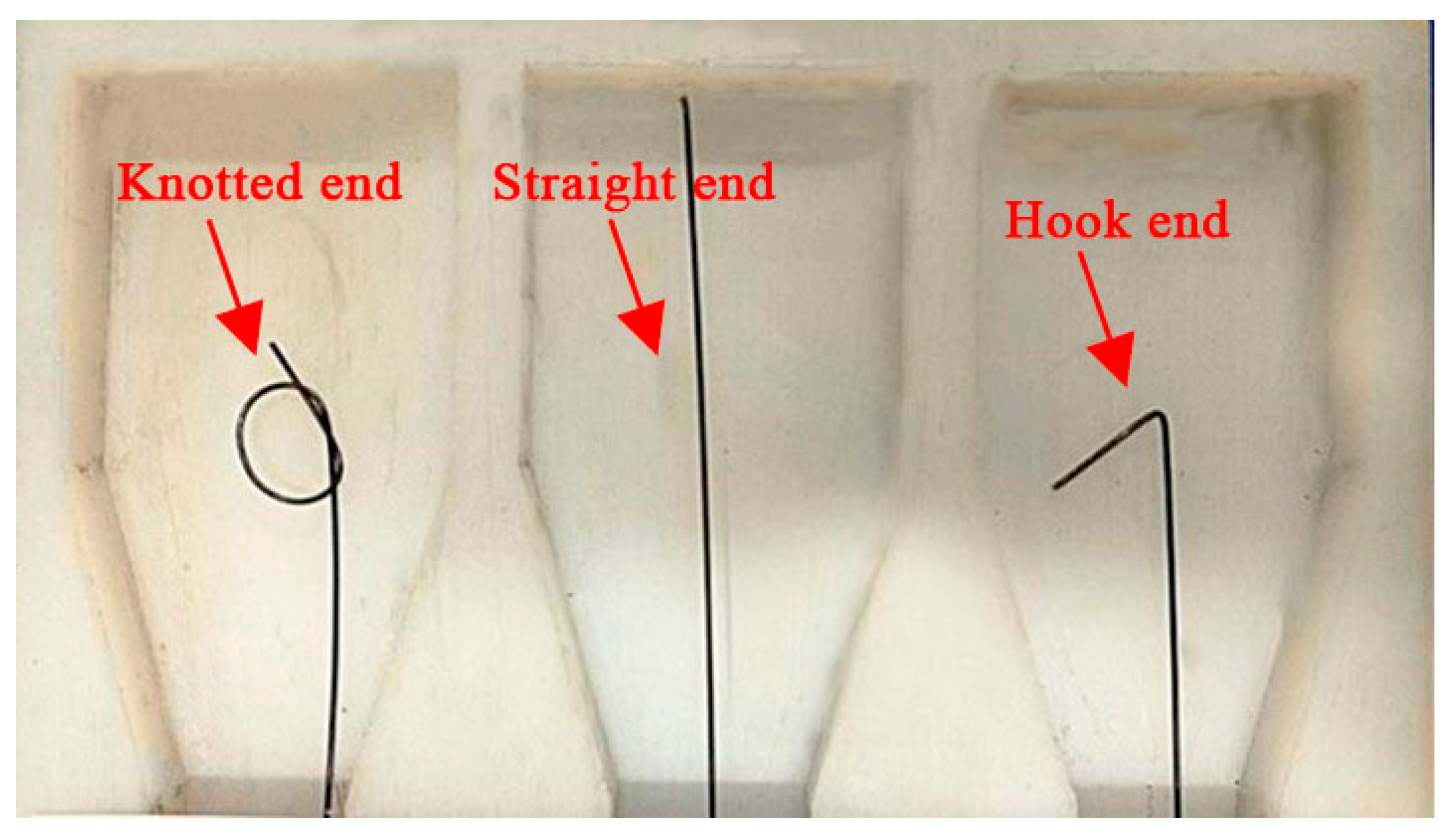
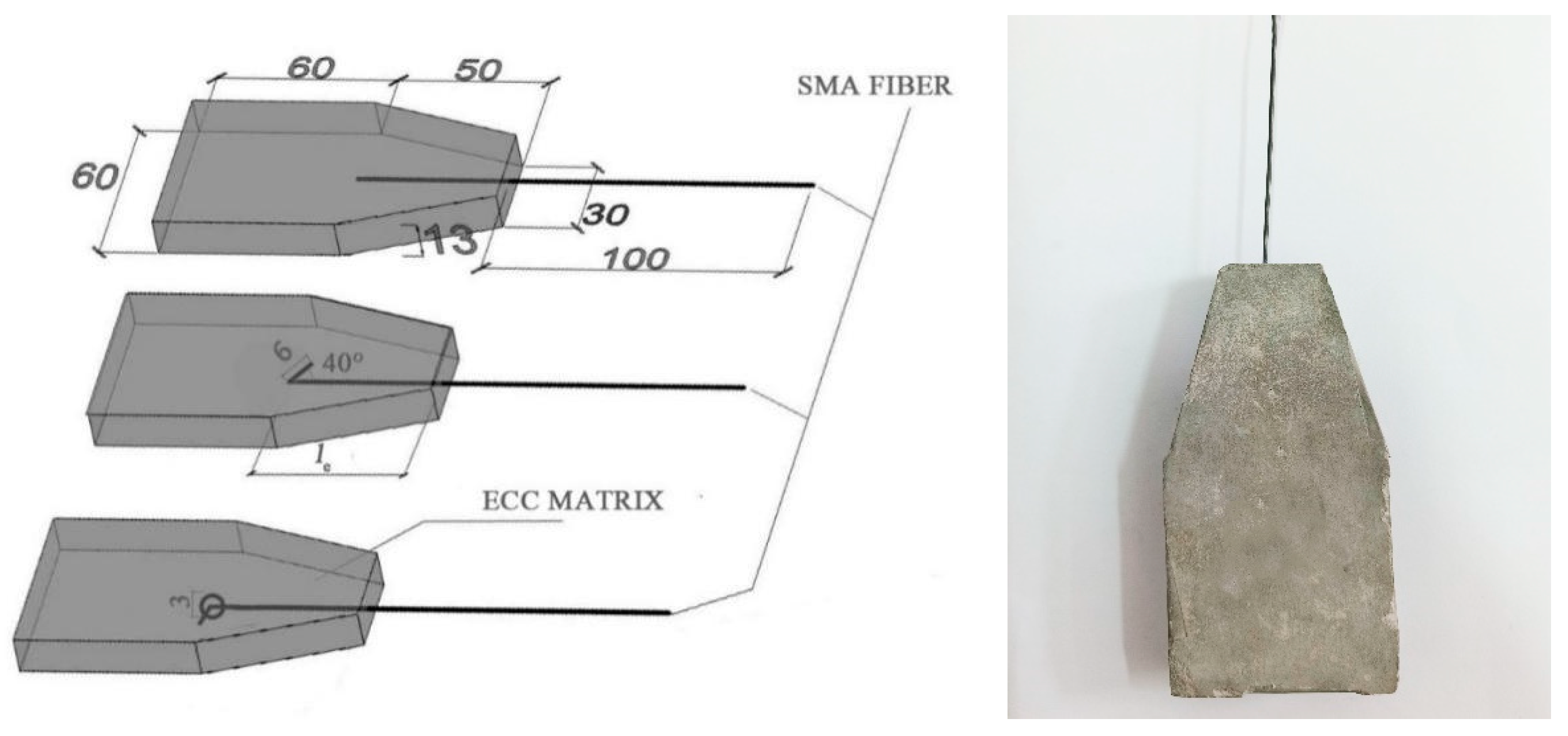
2.2. Specimen Design and Fabrication
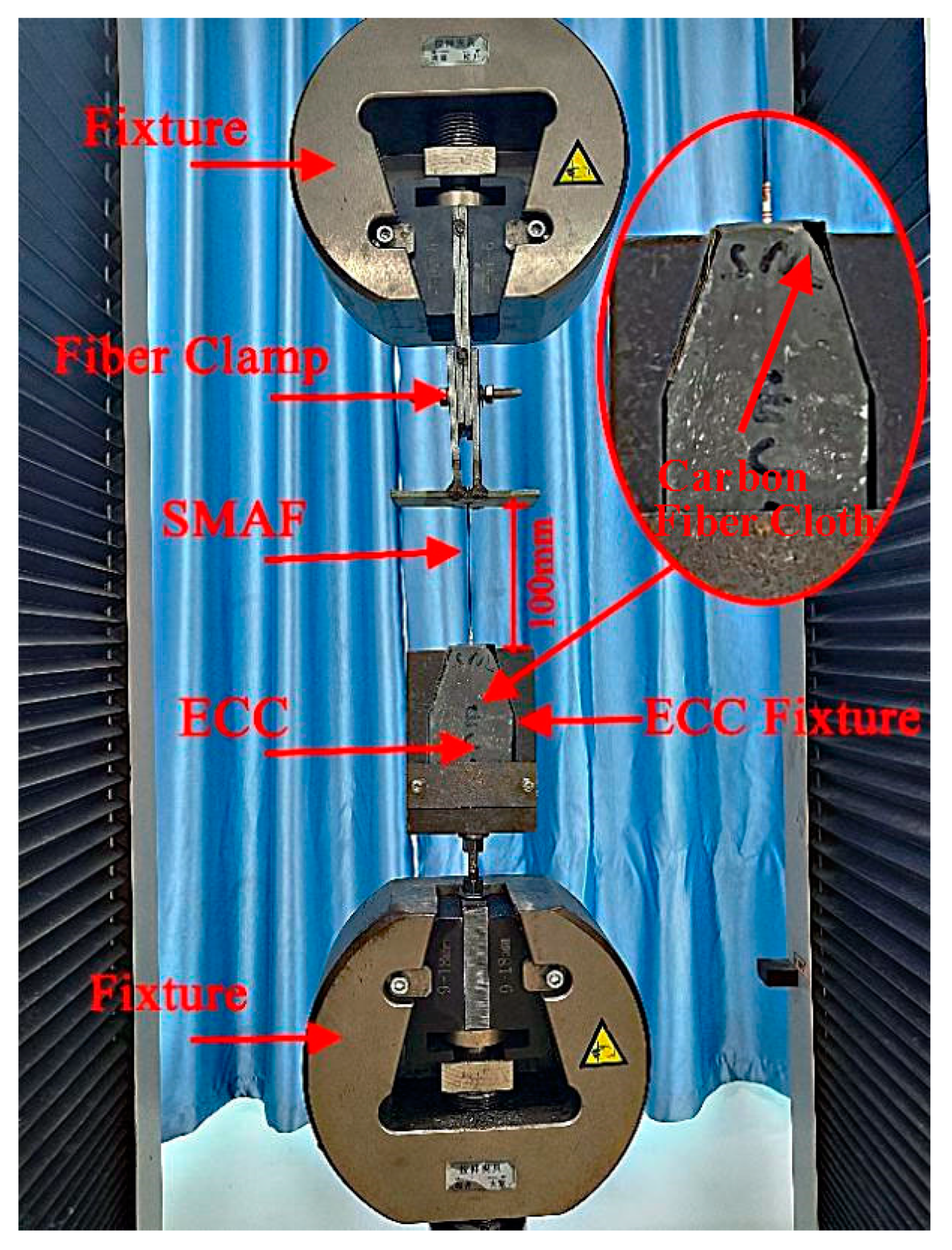
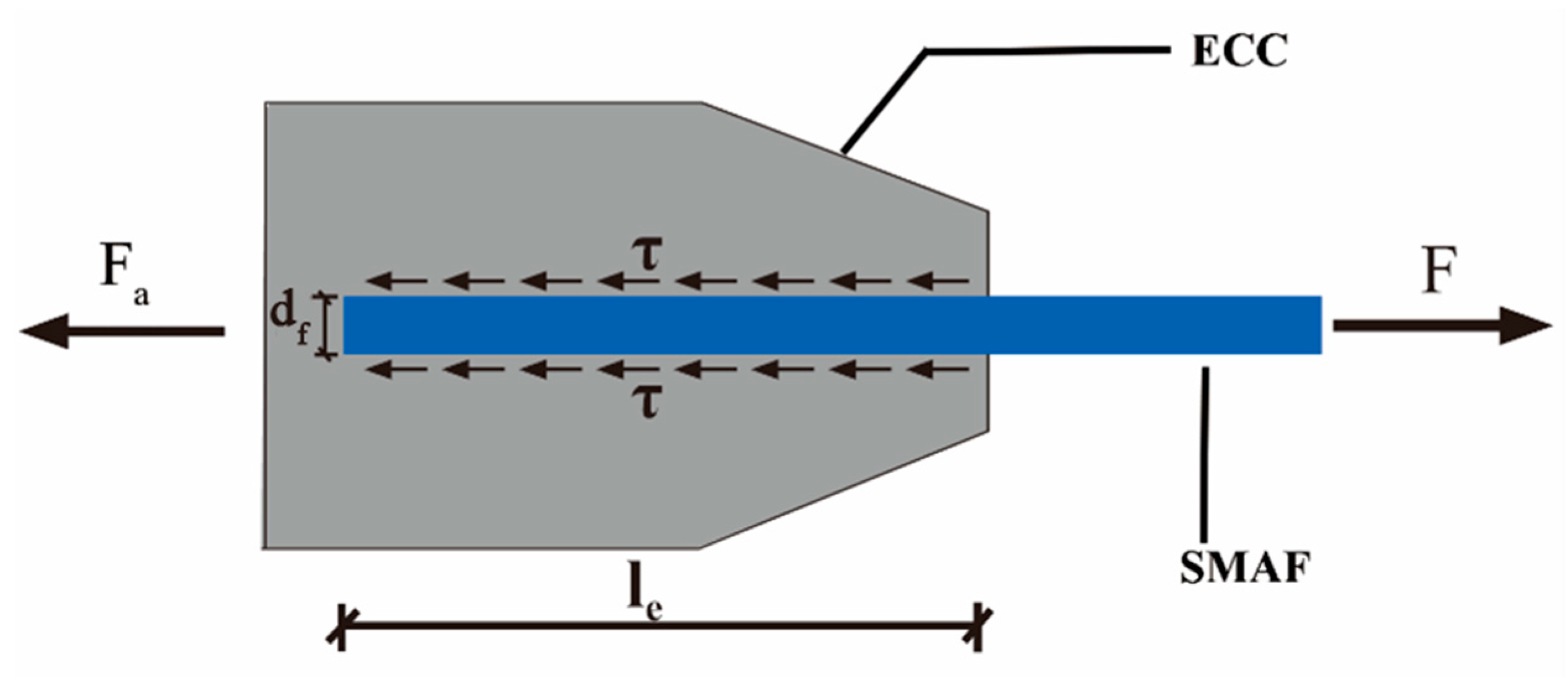
2.3. Test Device and Test Method
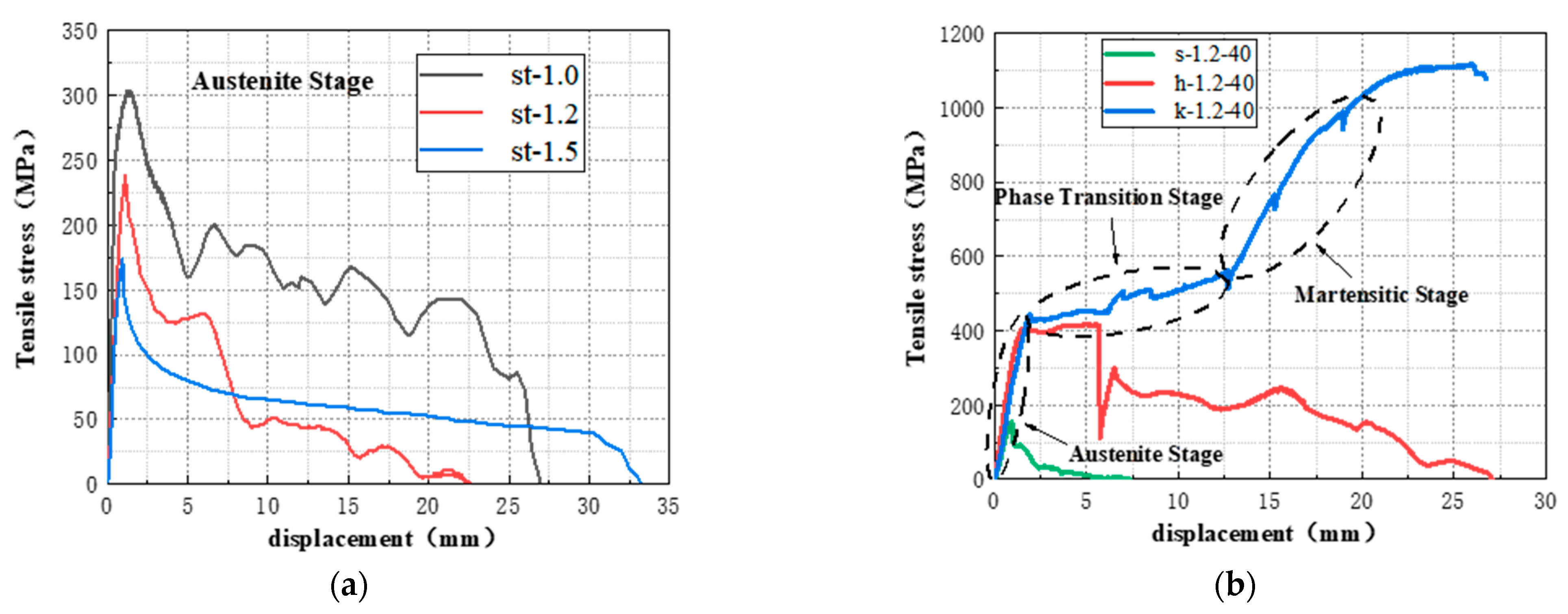
3. Results of Pullout Tests
3.1. Pullout Mechanical Properties
3.1.1. The First Group
3.1.2. The Second Group
3.1.3. The Third Group
3.1.4. The Fourth Group
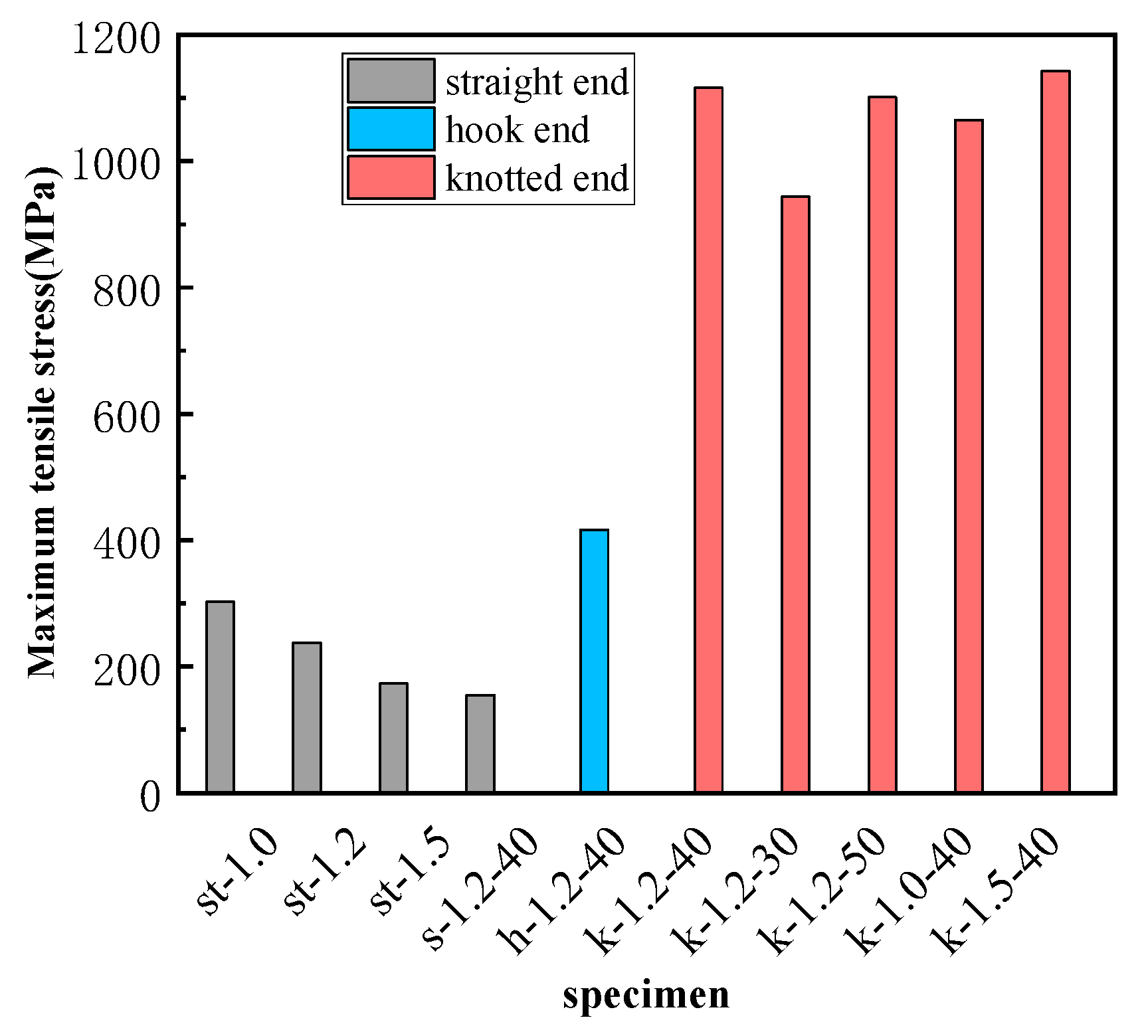
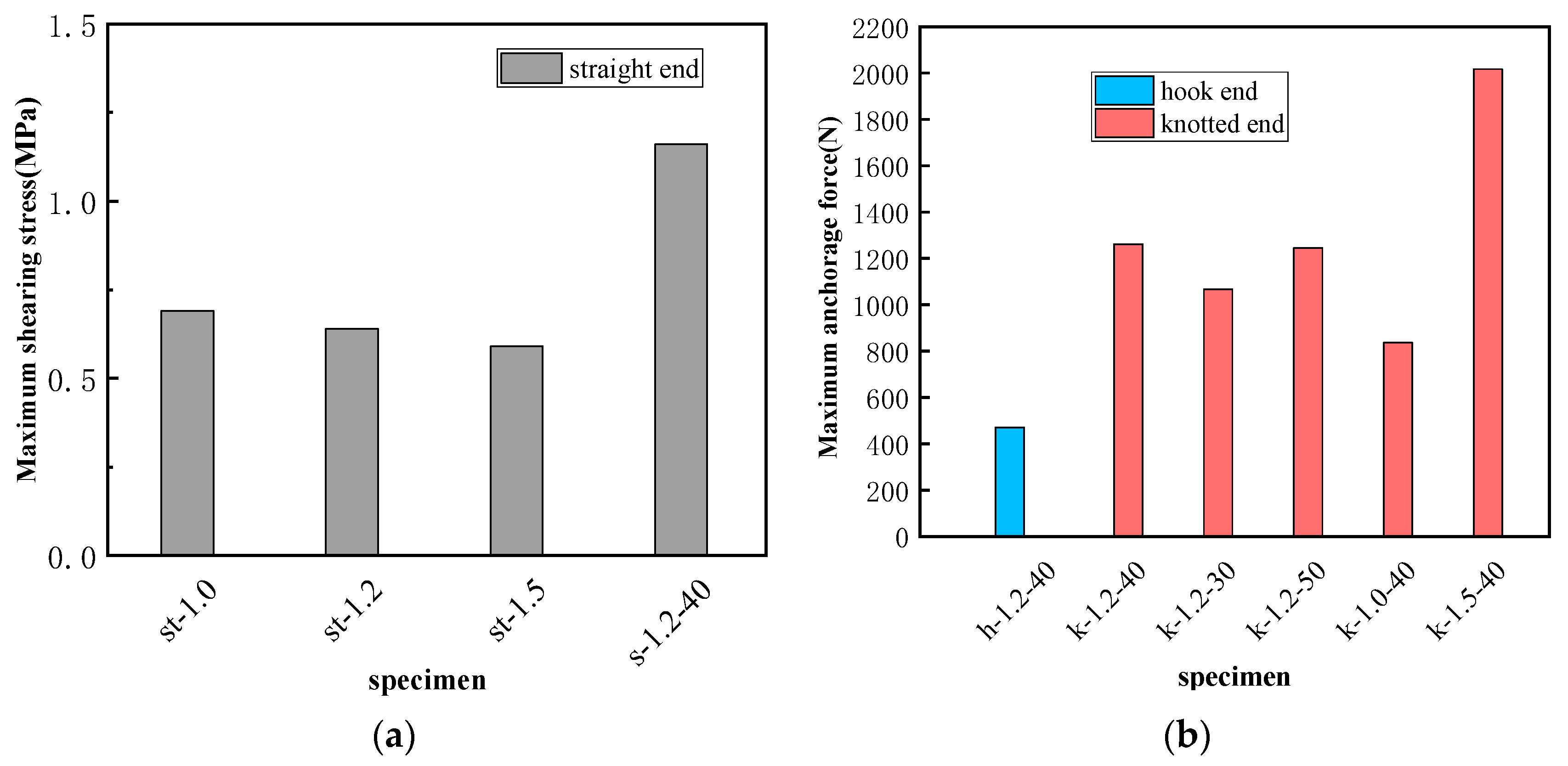
3.2. Bond-Bearing Capacity of SMA Fibers
3.2.1. Calculation Model of Bond-Bearing Capacity
3.2.2. Calculation Result and Comparison Analysis
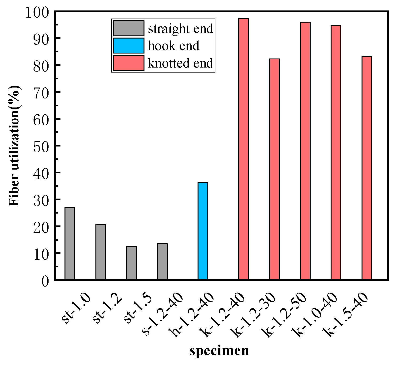
3.3. Utilization Rate of SMA Strength
4. Summary and Conclusions
- By setting the proper shaping of the end anchorage, the bonding performance between SMA fiber and ECC matrix can be effectively improved, which provides the basic conditions for making full use of the superelasticity of SMA material.
- The use of a knotted end in SMA fibers provides sufficient anchoring force to ensure the full utilization of SMA superelasticity. The pullout stress of the knotted end SMA fiber can reach a maximum value of 1116 MPa, which is significantly greater than the martensitic transformation stress. Furthermore, the maximum anchoring force can reach 2017 N, and the fiber strength utilization rate exceeds 80%.
- Straight end and hook end cannot provide sufficient bond strength or anchoring force. Due to the anchoring force provided by the hook end, the pullout stress can reach the martensitic transformation start stress. However, the stress concentration at the hook results in the anchorage failure, and thus the superelasticity of SMA can not be fully used.
- For SMA fibers with knotted end, increasing the fiber diameter can significantly increase the anchoring force, thus obtained higher pullout stress, but the fiber strength utilization rate will decrease. In addition, properly increasing the bond length can also increase the anchorage force, but there is an effective bond length between SMA fiber and ECC matrix. When the bond length is close to or exceeds the effective bond length, the anchorage force cannot obviously increase. Fiber bond length is recommended to be controlled at around 40 mm.
Author Contributions
Funding
Institutional Review Board Statement
Informed Consent Statement
Data Availability Statement
Conflicts of Interest
References
- Khan, K.; Ahmad, A.; Amin, M.N.; Ahmad, W.; Nazar, S.; Abu Arab, A.M. Comparative study of experimental and modeling of fly ash-based concrete. Materials 2022, 15, 3762. [Google Scholar] [CrossRef]
- Khan, K.; Ahmad, W.; Amin, M.N.; Aslam, F.; Ahmad, A.; Al-Faiad, M.A. Comparison of prediction models based on machine learning for the compressive strength estimation of recycled aggregate concrete. Materials 2022, 15, 3430. [Google Scholar] [CrossRef] [PubMed]
- Li, V.C. Engineered cementitious composites-tailored composites through micromechanical modeling. J. Adv. Concr. Technol. 1998, 1, 419–440. [Google Scholar]
- Tawfek, A.M.; Ge, Z.; Yuan, H.; Zhang, N. Influence of fiber orientation on the mechanical responses of engineering cementitious composite (ECC) under various loading conditions. J. Build. Eng. 2023, 63, 105518. [Google Scholar] [CrossRef]
- Wang, Z.B.; Han, S.; Sun, P.; Liu, W. Mechanical properties of polyvinyl alcohol-basalt hybrid fiber engineered cementitious composites with impact of elevated temperatures. J. Cent. South Univ. 2021, 28, 1459–1475. [Google Scholar] [CrossRef]
- Ismail, M.K.; Hassan, A.A.A.; Lachemi, M. Effect of fiber type on impact and abrasion resistance of engineered cementitious composite. ACI Mater. J. 2018, 115, 957–968. [Google Scholar] [CrossRef]
- Liu, Y.; Bao, Y.; Deng, L.; Zhang, Q. Experimental and finite element investigations on shear behaviors of stud connectors embedded in Engineered Cementitious Composite (ECC). Eng. Struct. 2023, 277, 115438. [Google Scholar] [CrossRef]
- Li, J.; Qiu, J.; Weng, J.; Yang, E.-H. Micromechanics of engineered cementitious composites (ECC): A critical review and new insights. Constr. Build. Mater. 2023, 362, 129765. [Google Scholar] [CrossRef]
- Hung, C.C.; Hsiao, H.J.; Shao, Y.; Lin, S. A comparative study on the seismic performance of RC beam-column joints retrofitted by ECC, FRP, and concrete jacketing methods. J. Build. Eng. 2023, 64, 105691. [Google Scholar] [CrossRef]
- Şahmaran, M.; Li, V.C. Engineered cementitious composites. Transp. Res. Rec. J. Transp. Res. Board 2010, 2164, 1–8. [Google Scholar] [CrossRef] [Green Version]
- Maalej, M.; Leong, K.S. Engineered cementitious composites for effective FRP-strengthening of RC beams. Compos. Sci. Technol. 2005, 65, 1120–1128. [Google Scholar] [CrossRef]
- Yuan, F.; Pan, J.; Dong, L.; Leung, C.Y. Mechanical behaviors of steel reinforced ECC or ECC/concrete composite beams under reversed cyclic loading. J. Mater. Civ. Eng. 2014, 26, 04014047.1–04014047.8. [Google Scholar] [CrossRef]
- Shan, Q.; Pan, J.; Chen, J. Mechanical behaviors of steel reinforced ECC/concrete composite columns under combined vertical and horizontal loading. J. Southeast Univ. (Engl. Ed.) 2015, 31, 259–265. [Google Scholar]
- Yuan, F.; Pan, J.; Xu, Z.; Leung, C.K.Y. A comparison of engineered cementitious composites versus normal concrete in beam-column joints under reversed cyclic loading. Mater. Struct. 2013, 46, 145–159. [Google Scholar] [CrossRef]
- Li, X.; Li, M.; Song, G. Energy-dissipating and self-repairing SMA-ECC composite material system. Smart Mater. Struct. 2015, 24, 025024. [Google Scholar] [CrossRef]
- Fang, C. SMAs for infrastructures in seismic zones: A critical review of latest trends and future needs. J. Build. Eng. 2022, 57, 104918. [Google Scholar] [CrossRef]
- Huang, B.; Lv, H.; Lao, Y.; Ding, J. Vibration control of superelastic SMA spring braces to a frame Structure under earthquake exciting. Earth Space 2021, 2021, 280–294. [Google Scholar]
- Fang, C.; Wang, W.; Qiu, C.; Hu, S.; MacRae, G.A.; Eatherton, M.R. Seismic resilient steel structures: A review of research, practice, challenges and opportunities. J. Constr. Steel Res. 2022, 191, 107172. [Google Scholar] [CrossRef]
- Ke, J.; Chen, L.; Gao, J.; Wu, Z.-Y. Improving the dynamic stiffness and vibration characteristics of 3D orthogonal woven by implanting SMA instead of a warp yarn. Compos. Struct. 2023, 307, 116637. [Google Scholar] [CrossRef]
- Yang, S.; Zhou, Z.; Li, K. Influence of fiber type and dosage on tensile property ofasphalt mixture using direct tensile test. Materials 2023, 16, 822. [Google Scholar] [CrossRef]
- Jani, J.M.; Leary, M.; Subic, A.; Gibson, M.A. A review of shape memory alloy research, applications and opportunities. Mater. Des. 2014, 56, 1078–1113. [Google Scholar] [CrossRef]
- Keyvan, S.; Hossein, A.; Mohammadreza, N.; Kordizadeh, F.; Dabbaghi, H.; Bayati, P.; Javanbakht, R.; Jahadakbar, A.; Elahinia, M. Additive manufacturing of NiTi shape memory alloy for biomedical applications: Review of the LPBF process ecosystem. JOM 2021, 73, 3771–3786. [Google Scholar]
- Pei, Q.; Wu, C.; Cheng, Z.; Ding, Y.; Guo, H. The seismic performance of new self-centering beam-column joints of conventional island main buildings in nuclear power plants. Materials 2022, 15, 1704. [Google Scholar] [CrossRef] [PubMed]
- Cortés-Puentes, L.; Zaidi, M.; Palermo, D.; Dragomirescu, E. Cyclic loading testing of repaired SMA and steel reinforced concrete shear walls. Eng. Struct. 2018, 168, 128–141. [Google Scholar] [CrossRef]
- Choi, E.; Kim, D.; Chung, Y.-S.; Nam, T.-H. Bond–slip characteristics of SMA reinforcing fibers obtained by pull-out tests. Mater. Res. Bull. 2014, 58, 28–31. [Google Scholar] [CrossRef]
- Dehghani, A.; Aslani, F.; Liu, Y. Pullout behaviour of shape memory alloy fibres in self-compacting concrete and its relation to fibre surface microtopography in comparison to steel fibres. Constr. Build. Mater. 2022, 323, 126570. [Google Scholar] [CrossRef]
- Choi, E.; Kim, D.; Lee, J.-H.; Ryu, G.-S. Monotonic and hysteretic pullout behavior of superelastic SMA fibers with different anchorages. Compos. Part B Eng. 2017, 108, 232–242. [Google Scholar] [CrossRef]
- Choi, E.; Mohammadzadeh, B.; Hwang, J.-H.; Kim, W.J. Pullout behavior of superelastic SMA fibers with various end-shapes embedded in cement mortar. Constr. Build. Mater. 2018, 167, 605–616. [Google Scholar] [CrossRef]
- Choi, E.; Mohammadzadeh, B.; Hwang, J.H.; Lee, J.-H. Displacement recovery capacity of superelatic SMA firbers reinforced cemetitious materials. Smart Struct. Syst. 2019, 24, 157–171. [Google Scholar]
- Choi, E.; Mohammadzadeh, B.; Kim, D.; Jeon, J.-S. A new experimental investigation into the effects of reinforcing mortar beams with superelastic SMA fibers on controlling and closing cracks. Compos. Part B Eng. 2018, 137, 140–152. [Google Scholar] [CrossRef]
- Ho, H.V.; Choi, E.; Park, S.J. Investigating stress distribution of crimped SMA fibers during pullout behavior using experimental testing and a finite element model. Compos. Struct. 2021, 272, 114254. [Google Scholar] [CrossRef]
- Yang, Z.; Deng, T.; Li, J.; Xu, C. Experimental study on self-centering performance of the SMA fiber reinforced ECC composite beam. Materials 2022, 15, 3062. [Google Scholar] [CrossRef]
- Ali, M.A.E.M. Mechanical performance of hybrid fibre-reinforced engineered cementitious composite incorporating NiTi-SMA short fibres. In Proceedings of the 11th ICCAE-11 Conference, London, ON, Canada, 19–21 April 2016. [Google Scholar]
- Dehghani, A.; Aslani, F. The effect of shape memory alloy, steel, and carbon fibres on fresh, mechanical, and electrical properties of self-compacting cementitious composites. Cem. Concr. Compos. 2020, 112, 103659. [Google Scholar] [CrossRef]
- Dehghani, A.; Aslani, F. The synergistic effects of shape memory alloy, steel, and carbon fibres with polyvinyl alcohol fibres in hybrid strain-hardening cementitious composites. Constr. Build. Mater. 2020, 252, 119061. [Google Scholar] [CrossRef]
- Chen, W.; Feng, K.; Wang, Y.; Lin, Y.; Qian, H. Evaluation of self-healing performance of a smart composite material (SMA-ECC). Constr. Build. Mater. 2021, 290, 123216. [Google Scholar] [CrossRef]
- Yang, Z.; Du, Y.; Liang, Y.; Ke, X. Mechanical behavior of shape memory alloy fibers embedded in engineered cementitious composite matrix under cyclic pullout loads. Materials 2022, 15, 4531. [Google Scholar] [CrossRef]
- Chinese Standard JC/T 2461-2018; Standard Test Method for the Mechanical Properties of Ductile Fiber Reinforced Cementitious Composites. General Administration of Quality Supervision, Inspection and Quarantine of the People’s Republic of China and Ministry of Industry and Information Technology of the People’s Republic of China: Beijing, China, 2018.
- Cheng, Z.; Liu, Z.; Hao, H.; Lu, Y.; Li, S. Multi-scale effects of tensile properties of lightweight engineered geopolymer composites reinforced with MWCNTs and steel-PVA hybrid fibers. Constr. Build. Mater. 2022, 342, 128090. [Google Scholar] [CrossRef]
- Choi, E.; Dong, J.K.; Jeon, C.; Gin, S. New SMA short fibers for cement composites manufactured by cold drawing. J. Mater. Sci. Res. 2016, 5, 68. [Google Scholar]
- Ho, H.V.; Choi, E.; Kang, J.W. Analytical bond behavior of cold drawn SMA crimped fibers considering embedded length and fiber wave depth. Rev. Adv. Mater. Sci. 2021, 60, 862–883. [Google Scholar] [CrossRef]
- Lu, X.Z.; Teng, J.G.; Ye, L.P.; Jiang, J.J. Bond–slip models for FRP sheets/plates bonded to concrete. Eng. Struct. 2005, 27, 920–937. [Google Scholar] [CrossRef]
- Wiemer, N.; Wetzel, A.; Schleiting, M.; Krooß, P.; Vollmer, M.; Niendorf, T.; Böhm, S.; Middendorf, B. Effect of fibre material and fibre roughness on the pullout behaviour of metallic micro fibres embedded in UHPC. Materials 2020, 13, 3128. [Google Scholar] [CrossRef] [PubMed]
- Robins, P.; Austin, S.; Jones, P. Pull-out behaviour of hooked steel fibres. Mater. Struct. 2002, 35, 434–442. [Google Scholar] [CrossRef]
- Cunha, V.M.C.F.; Barros, J.A.O.; Sena-Cruz, J. Pullout behavior of steel fibres in self-compacting concrete. Am. Soc. Civ. Eng. 2010, 22, 1–9. [Google Scholar]


| Raw Materials | Cement | Fly Ash | Silica Sand | Water | PS | PVA * (%) |
|---|---|---|---|---|---|---|
| Mix proportion | 1.0 | 2.4 | 0.36 | 0.26 | 0.0082 | 2.0 |
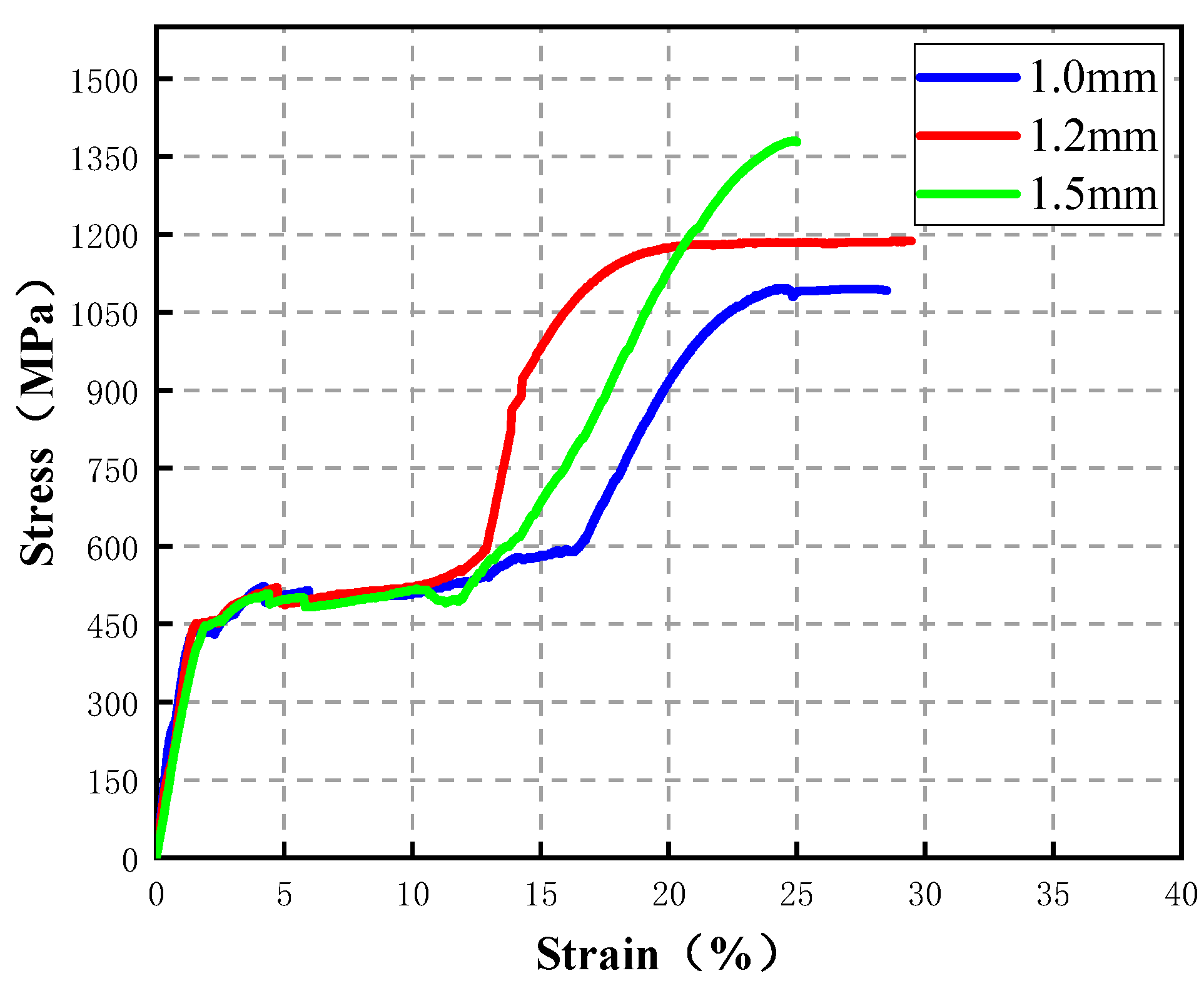
| Diameter/mm | Start Point of Stress Platform | End Point of Stress Platform | Tensile Strength a/MPa | Ultimate Strain b/% | ||
|---|---|---|---|---|---|---|
| Strain/% | Stress/MPa | Strain/% | Stress/MPa | |||
| 1.0 | 1.55 | 450 | 17.22 | 591 | 1123 | 28.6 |
| 1.2 | 1.65 | 468 | 13.7 | 581 | 1147 | 29.1 |
| 1.5 | 2.08 | 459 | 12.5 | 520 | 1372 | 25.4 |
| Group | Specimen | Diameter (mm) | End Shape | Bonding Length (mm) |
|---|---|---|---|---|
| 1 | st-1.0 | 1.0 | Straight | 110 (through) |
| st-1.2 | 1.2 | |||
| st-1.5 | 1.5 | |||
| 2 | s-1.2-40 | 1.2 | Straight | 40 |
| h-1.2-40 | Hook | |||
| k-1.2-40 | Knotted | |||
| 3 | k-1.2-30 | 1.2 | Knotted | 30 |
| k-1.2-40 | 40 | |||
| k-1.2-50 | 50 | |||
| 4 | k-1.0-40 | 1.0 | Knotted | 40 |
| k-1.2-40 | 1.2 | |||
| k-1.5-40 | 1.5 |
| Group | Specimen | Fmax/N | σf,max/MPa | Dmax/mm |
|---|---|---|---|---|
| 1 | st-1.0 | 237 | 302 | 26.3 |
| st-1.2 | 269 | 238 | 23.3 | |
| st-1.5 | 305 | 173 | 31.5 | |
| 2 | s-1.2-40 | 175 | 155 | 7.41 |
| h-1.2-40 | 471 | 416 | 27.2 | |
| k-1.2-40 | 1261 | 1116 | 27.1 | |
| 3 | k-1.2-30 | 1067 | 943 | 33.9 |
| k-1.2-40 | 1261 | 1116 | 27.1 | |
| k-1.2-50 | 1244 | 1101 | 23.6 | |
| 4 | k-1.0-40 | 835 | 1064 | 25.0 |
| k-1.2-40 | 1261 | 1116 | 27.1 | |
| k-1.5-40 | 2017 | 1142 | 25.8 |
| Specimen | df/mm | le/mm | τmax/MPa | Fa (N) |
|---|---|---|---|---|
| st-1.0 | 1.0 | 110 | 0.69 | / |
| st-1.2 | 1.20 | 110 | 0.64 | / |
| st-1.5 | 1.50 | 110 | 0.59 | / |
| s-1.2-40 | 1.20 | 40.0 | 1.16 | / |
| h-1.2-40 | 1.20 | 40.0 | / | 471 |
| k-1.2-40 | 1.20 | 40.0 | / | 1261 |
| k-1.2-30 | 1.20 | 30.0 | / | 1067 |
| k-1.2-50 | 1.20 | 50.0 | / | 1244 |
| k-1.0-40 | 1.00 | 40.0 | / | 835 |
| k-1.5-40 | 1.50 | 40.0 | / | 2017 |
| Specimen | fy (MPa) | uf (%) |
|---|---|---|
| st-1.0 | 1123 | 26.9 |
| st-1.2 | 1147 | 20.7 |
| st-1.5 | 1372 | 12.6 |
| s-1.2-40 | 1147 | 13.5 |
| h-1.2-40 | 1147 | 36.3 |
| k-1.2-40 | 1147 | 97.2 |
| k-1.2-30 | 1147 | 82.2 |
| k-1.2-50 | 1147 | 95.9 |
| k-1.0-40 | 1123 | 94.8 |
| k-1.5-40 | 1372 | 83.2 |
Disclaimer/Publisher’s Note: The statements, opinions and data contained in all publications are solely those of the individual author(s) and contributor(s) and not of MDPI and/or the editor(s). MDPI and/or the editor(s) disclaim responsibility for any injury to people or property resulting from any ideas, methods, instructions or products referred to in the content. |
© 2023 by the authors. Licensee MDPI, Basel, Switzerland. This article is an open access article distributed under the terms and conditions of the Creative Commons Attribution (CC BY) license (https://creativecommons.org/licenses/by/4.0/).
Share and Cite
Yang, Z.; Gong, X.; Wu, Q.; Fan, L. Bonding Mechanical Properties between SMA Fiber and ECC Matrix under Direct Pullout Loads. Materials 2023, 16, 2672. https://doi.org/10.3390/ma16072672
Yang Z, Gong X, Wu Q, Fan L. Bonding Mechanical Properties between SMA Fiber and ECC Matrix under Direct Pullout Loads. Materials. 2023; 16(7):2672. https://doi.org/10.3390/ma16072672
Chicago/Turabian StyleYang, Zhao, Xiaojun Gong, Qing Wu, and Lin Fan. 2023. "Bonding Mechanical Properties between SMA Fiber and ECC Matrix under Direct Pullout Loads" Materials 16, no. 7: 2672. https://doi.org/10.3390/ma16072672