
A Review of the Extruder System Design for Large-Scale Extrusion-Based 3D Concrete Printing


Abstract
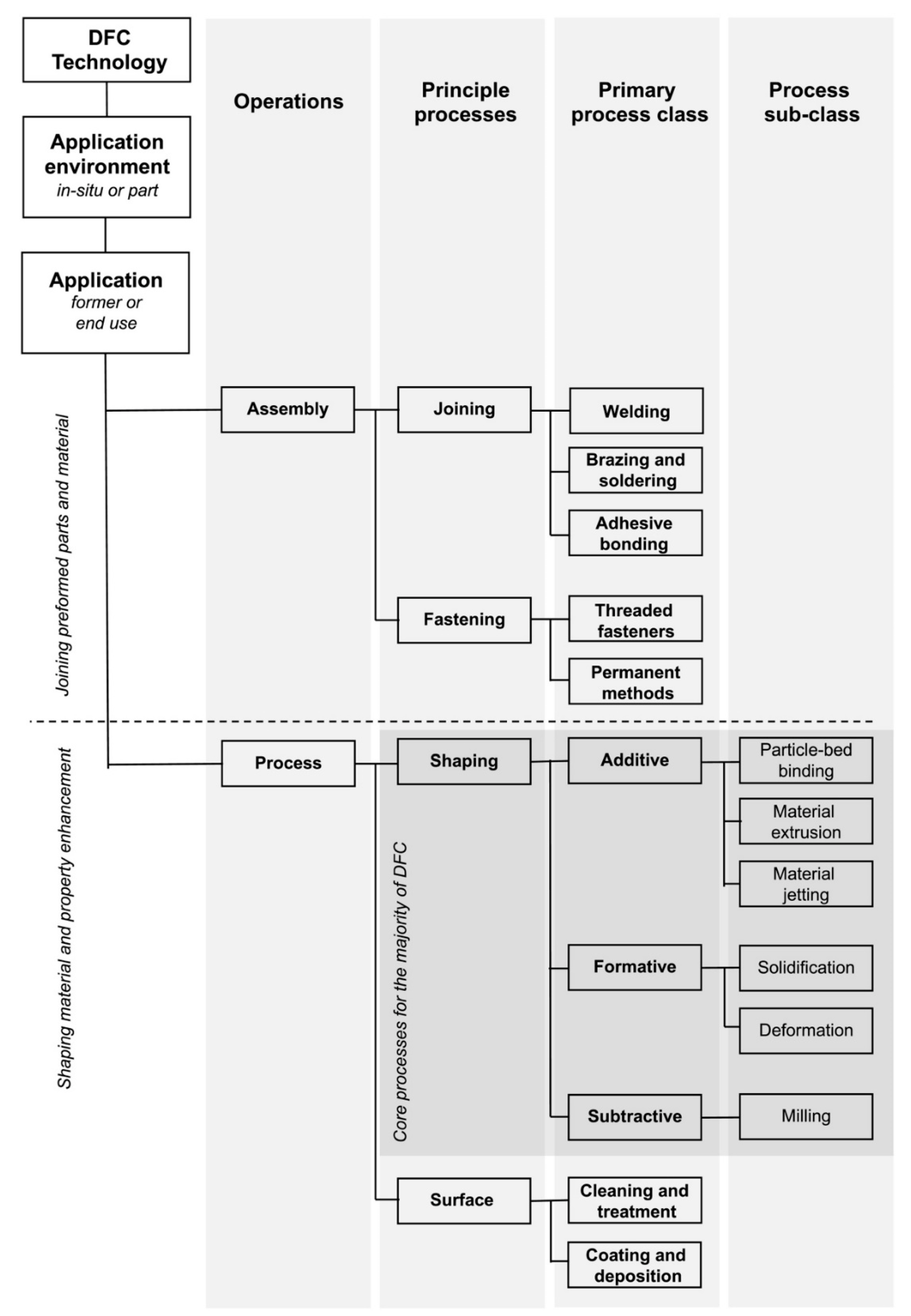
:1. Introduction
2. Extrusion Process and Extruder System
2.1. General Extruder System Design
2.1.1. Extrusion Mechanism
2.1.2. Extruder Wall Roughness
2.2. Chamber Design
2.2.1. Chamber Number
2.2.2. Chamber Diameter and Length
2.2.3. Chamber Tapering
2.3. Outlet Design
2.3.1. Outlet Form
2.3.2. Outlet Orientation
2.3.3. Outlet Tapering
2.3.4. Outlet Cross-Section Shape
2.3.5. Outlet Size

| Reference | Maximum Aggregate Size (mm) | Fiber Length (L × D mm) | Outlet Exit Size (D/L × W mm) | BE | Standoff Distance (mm) | Extrusion Velocity (mm/s) |
|---|---|---|---|---|---|---|
| [84] | 2 | - | 28 × 18 | 9 | - | - |
| [85] | 4.75 | - | 25 | 5.26 | - | - |
| [86] | 1.18 | - | 30 × 15 | 12.71 | - | - |
| [87] | 1.20 | - | 30 × 15 | 12.50 | - | - |
| [88] | 4 | - | 25 | 6.25 | - | - |
| [89] | 1.15 | - | 15 × 7 | 6.09 | - | 476.19 |
| [90] | 1 | - | 40 × 10, 25 × 25 | 10, 25 | 10, 25 | - |
| [91] | 2 | - | 20 | 10 | - | - |
| [92] | 1.18 | 12 × 0.0014 | 13 × 30 | 11.02 | - | - |
| [93] | 2 | - | 19 | 9.50 | 10 | - |
| [37] | 1 | 6 | 25 × 15 | 15 | 15 | - |
| [94] | 1.2 | - | 30 × 15 | 12.50 | 15 | 66.6 |
| [95] | 0.9 | - | 30 | 33.33 | 0–10 | 28.29 |
| [96] | 1.15 | - | - | - | 0, 2, 4 | - |
| [22] | - | - | 4, 10 | - | - | 31.83, 5.10 |
| [25] | - | - | 45 | - | - | 50–120 |
| [97] | 0.5 | - | 20 | - | 10 | 47.22 |
| [83] | - | - | 20 | - | 8–20 | 43.19 |
| [81] | 1.2 | - | 10–24 × 10–24 | - | - | - |
| [98] | - | - | 30 × 15 | - | - | - |
| [80] | 10 | - | 30 | - | - | 35.37 |
| [99] | 9.5 | - | 29.2 | 3.07 | - | 422.60 |
| [100] | 2 | 12 × 0.04 | 30 × 20 | 10 | - | 44 |
| [68] | - | - | 20 | - | - | - |
| [101] | - | - | 20 × 20, 30 × 10 | - | - | - |
| [102] | 0.5 | 6 | 25 | 50 | - | - |
| [29] | - | - | - | - | - | - |
| [38] | 1 | 9 × 0.023 | 8 × 30 | 8 | - | - |
| [103] | 0.5 | - | 25 | 50 | 7.5–17.5 | 40 |
| [104] | 2 | - | - | - | - | - |
| Large Outlet Size | Small Outlet Size | |
|---|---|---|
| Extrusion resistive forces | • Lower Fpl and Fnf | • Higher Fpl and Fnf |
| Extrusion behaviors | • Lower shearing • Reduce the consolidation and phase separation and dead zone formation • Lower risk of blockage • Lower extrusion pressure required | • Higher shearing • Increase the consolidation and phase separation and dead zone formation • Higher risk of blockage • Higher extrusion pressure required |
| Extrudability | • More smooth extrusion | • Less smooth extrusion |
| Economic aspects and technical complexity | • Lower energy consumption • No additional technical complexity | • Higher energy consumption • No additional technical complexity |
3. Deposition Process and Positioning System
| Reference | Positioning System | Degree of Freedom | Build Volume (L × W × H m)/Reach (m) |
|---|---|---|---|
| [29] | Gantry | 3-axis | 20 × 18 × 18 |
| [94] | Gantry | 3-axis | 1.2 × 1.2 × 1.0 |
| [38] | Gantry | 3-axis | 0.5 × 0.39 × 1.1 |
| [103] | Robotic arm | 6-axis Fanuc R-2000iC/165F | - |
| [92] | Gantry | 3-axis | - |
| [95] | Gantry | 3-axis | 3.0 × 3.0 × 3.0 |
| [25] | Robotic arm | 6-axis KUKA KR60 HA | - |
| [80] | Gantry | 3-axis | 1.8 × 1.8 × 1.5 |
| [90] | Gantry | 4-axis | 9 × 4.5 × 2.8 |
| [93] | Gantry | 3-axis | 0.15 × 0.15 × 0.12 |
| [89] | Robotic arm | 6-axis Denso | - |
| [97] | Robotic arm | 6-axis FANUC R-2000iC/165F | - |
| [83] | Gantry | 3-axis | - |
| [104] | Robotic arm and gantry | 6-axis ABB IRB 4600 robotic arm hanging on a Güdel 3-axis gantry | - |
| [99] | Gantry | 3-axis | 10.36 × 2.74 × 3.05 |
| [100] | Gantry | 3-axis | 0.40 × 0.30 × 0.30 |
| [101] | Gantry | 4-axis | - |
| [108] | Gantry | 4-axis | - |
| [3] | Gantry | 3-axis | Infinite × 14.6 × 8.1 |
| [110] | Gantry | 3-axis | Infinite × 8.53 × 2.59 |
| [116] | Robotic arm | 6-axis | 2.65–3.50 |
| [116] | Robotic arm | 7-axis | Infinite × Infinite × ~3 |
| [120] | Delta system | - | 17 × 12 × 5 |
| [4] | Delta system | - | 7 × 7 × 12 m |
4. Advanced Sub-Processes and Advanced Fittings
4.1. Secondary Mixing Sub-Process and System
4.2. Setting/Fluid on Demand Sub-Processes and Systems Based on External Solicitations
4.3. In-Process Reinforcement Sub-Process and System
4.4. Interlayer Bonding Enhancement Sub-Process and System
4.5. Finishing Sub-Process and System
4.6. Support Placement Sub-Process and System
4.7. Monitoring and Feedback Sub-Process and System
5. Discussion
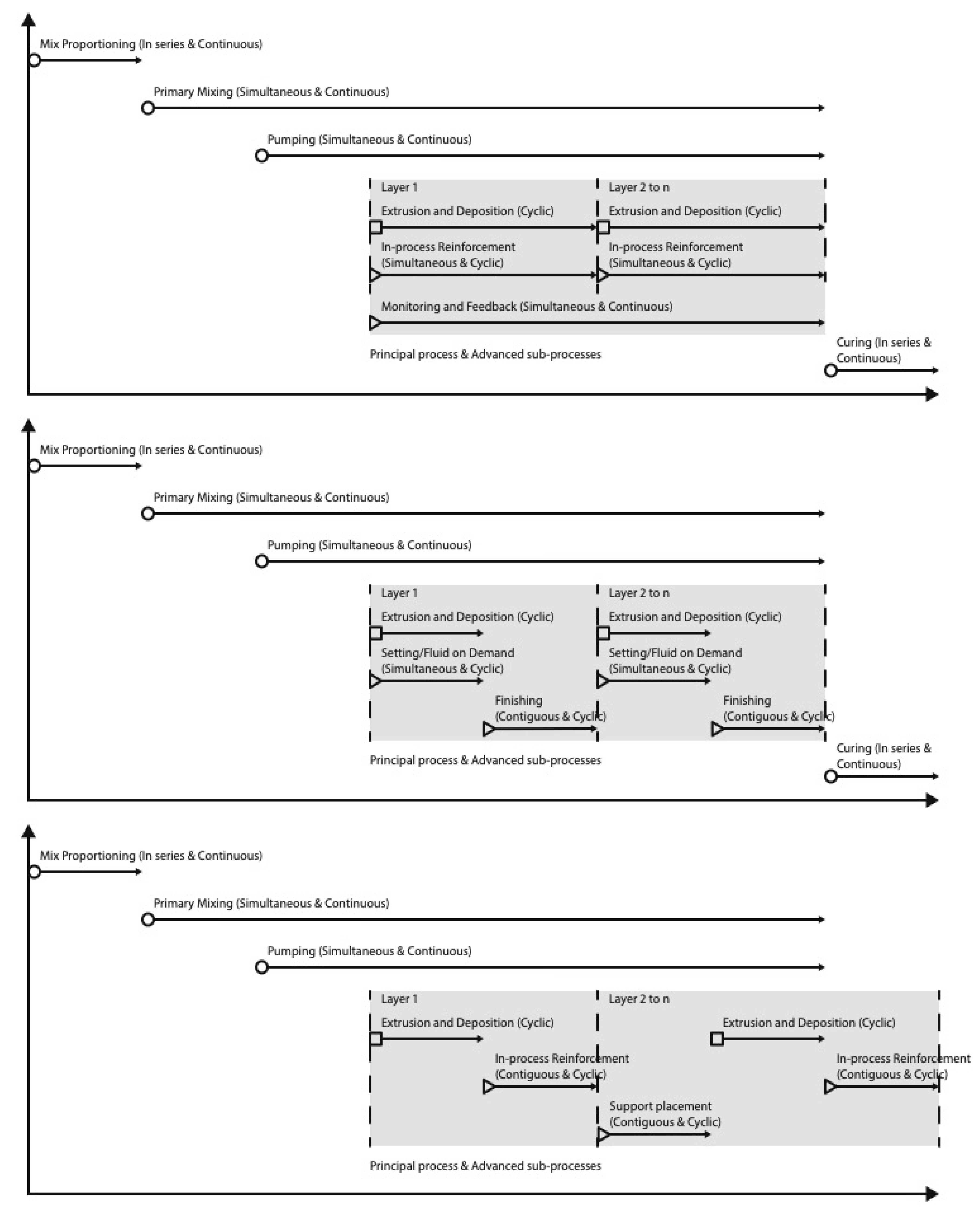
5.1. Process Chain of E3DCP System
5.2. E3DCP Classification Framework
6. Conclusions
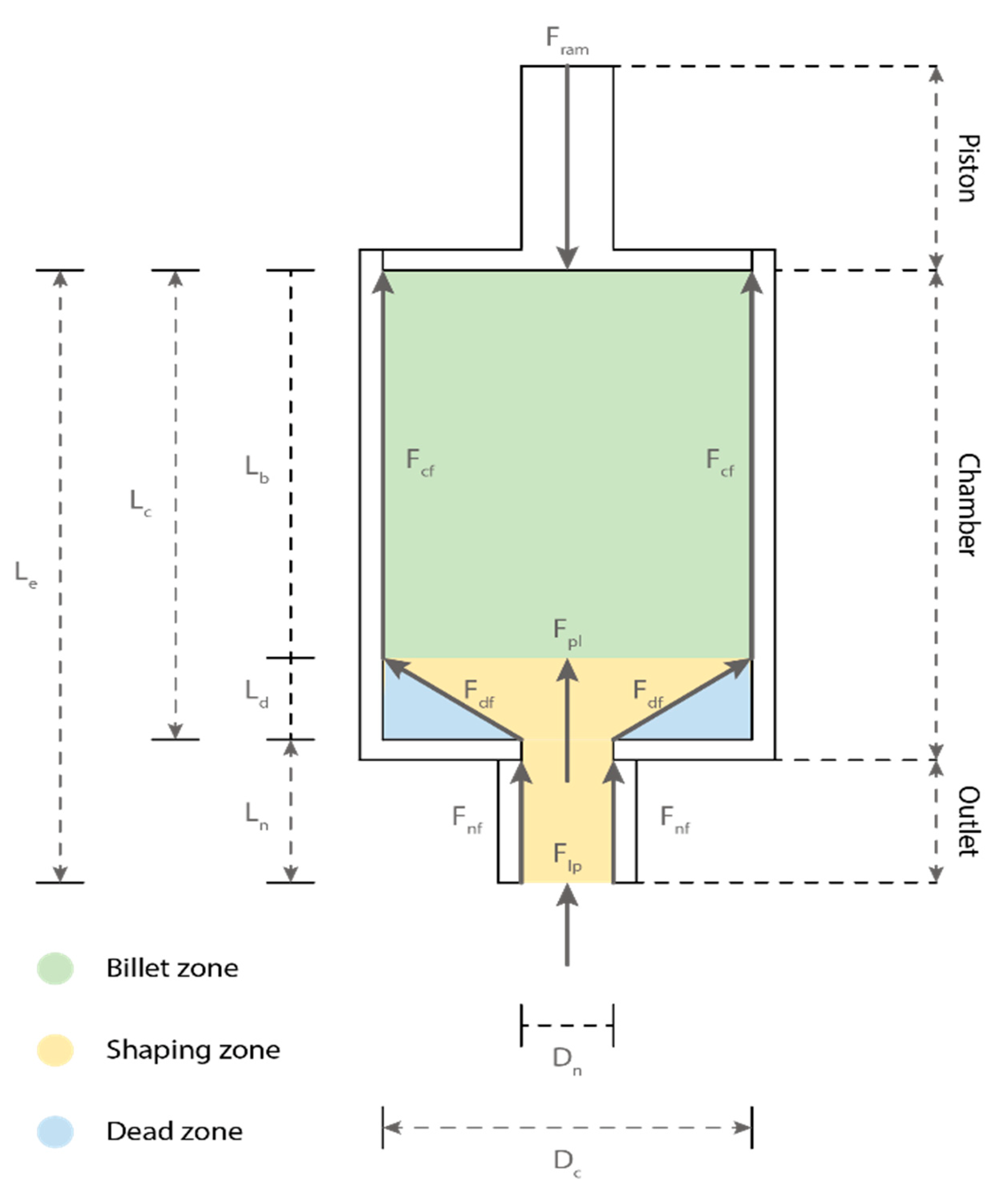
- The concrete extrusion process originates from the competition between the extrusion drive force, Fe and extrusion resistive forces, which may include chamber wall shear force Fcf, shaping force Fpl, nozzle wall shear force Fnf, dead zone shear force Fdf and layer pressing force, Flp;
- The three possible extrusion mechanisms—primary motivation, ram extrusion and screw extrusion—provide pumping and gravity force Fpg, ram extrusion force Fram and screw extrusion force Fscrew, respectively;
- A low extruder wall roughness can reduce Fcf and Fnf, thereby reducing the extrusion pressure;
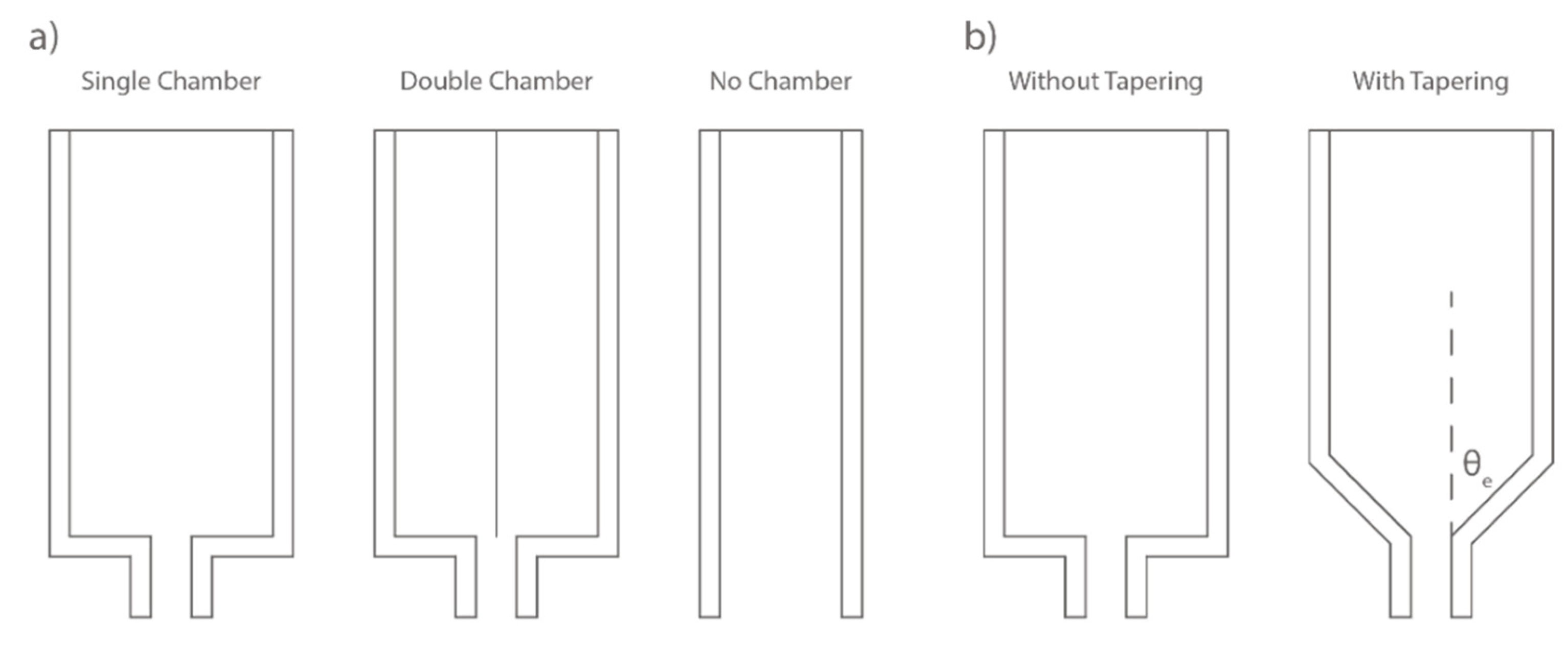
- The chamber design needs to consider chamber number, chamber length and diameter, and chamber tapering. A smaller chamber diameter increases Fpl; and the chamber tapering can generally reduce Fpl and extrusion pressure;
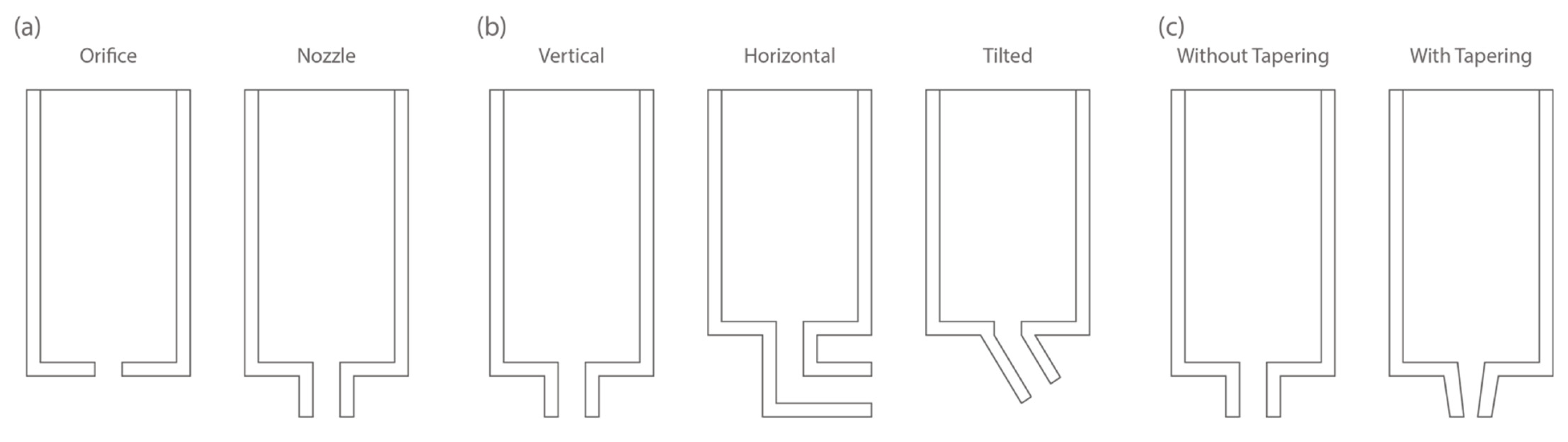
- The outlet design needs to consider outlet orientation, outlet form, outlet tapering, outlet cross-section shape, and outlet exit size. The outlet form of the orifice is associated with lower extrusion pressure whereas the outlet form of the nozzle has higher extrusion pressure due to the presence of Fnf; the presence of outlet tapering increases Fnf; the circular cross-section more likely induces a free flow extrusion mode, whereas the rectilinear cross-section more likely induces an infinite brick extrusion mode; a smaller outlet exit size corresponds to enhanced Fpl and Fnf;
- The advanced fittings include the secondary mixing, setting-/fluid-on-demand, in-process reinforcement, interlayer bonding enhancement, finishing, support placement, and monitoring and feedback processes. They are still at a nascent stage of application in E3DCP systems, and the incorporation of advanced fittings could increase the complexity of the E3DCP process chain, requiring more investigations in the respects of: (a) the compatibility between each advanced fitting and the printing system; (b) the compatibility between different advanced fittings; and (c) the optimal sequence of advanced sub-processes;
- The most crucial aspect of the E3DCP extruder system is the understanding of how the coupling between the mechanical designs, different concrete materials (e.g., low- and high-viscosity, low- and high-solid concentration), and operational design (e.g., pumping pressure) can influence the extrusion forces and phenomena, from which one can draw guidelines for the corresponding mechanical system and material combinations that can optimize the extrudability. As one can tell, considerable research efforts are required to fully understand this chain effect: the coupling of mechanical and material designs, the competition of extrusion forces, the occurrence of various extrusion phenomena, and the extrudability of the overall setting.
Author Contributions
Funding
Institutional Review Board Statement
Informed Consent Statement
Data Availability Statement
Conflicts of Interest
References
- Buswell, R.; da Silva, W.L.; Bos, F.; Schipper, H.; Lowke, D.; Hack, N.; Kloft, H.; Mechtcherine, V.; Wangler, T.; Roussel, N. A process classification framework for defining and describing Digital Fabrication with Concrete. Cem. Concr. Res. 2020, 134, 106068. [Google Scholar] [CrossRef]
- XtreeE. Available online: https://xtreee.com/en/ (accessed on 3 August 2022).
- COBOD. Available online: www.cobod.com (accessed on 3 August 2022).
- WASP. BigDelta 3D Concrete Printer. Available online: https://www.3dwasp.com/en/giant-3d-printer-bigdelta-wasp-12mt/ (accessed on 3 August 2022).
- Sika Group. 2020. Available online: https://www.sika.com/en/knowledge-hub/3d-concrete-printing.html (accessed on 3 August 2022).
- Lowke, D.; Vandenberg, A.; Pierre, A.; Thomas, A.; Kloft, H.; Hack, N. Injection 3D concrete printing in a carrier liquid—Underlying physics and applications to lightweight space frame structures. Cem. Concr. Compos. 2021, 124, 104169. [Google Scholar] [CrossRef]
- Lloret, E.; Shahab, A.R.; Linus, M.; Flatt, R.J.; Gramazio, F.; Kohler, M.; Langenberg, S. Complex concrete structures. Comput. Des. 2015, 60, 40–49. [Google Scholar] [CrossRef]
- Hack, N.; Kloft, H. Shotcrete 3D Printing Technology for the Fabrication of Slender Fully Reinforced Freeform Concrete Elements with High Surface Quality: A Real-Scale Demonstrator. In DC 2020: Second RILEM International Conference on Concrete and Digital Fabrication; Springer International Publishing: Berlin/Heidelberg, Germany, 2020; Volume 28, pp. 1128–1137. [Google Scholar] [CrossRef]
- Wangler, T.; Pileggi, R.; Gürel, S.; Flatt, R.J. A chemical process engineering look at digital concrete processes: Critical step design, inline mixing, and scaleup. Cem. Concr. Res. 2022, 155, 106782. [Google Scholar] [CrossRef]
- Perrot, A.; Rangeard, D.; Naidu, V.; Mechtcherine, V. Extrusion of cement—Based materials—An overview. RILEM Tech. Lett. 2019, 2018, 91–97. [Google Scholar] [CrossRef] [Green Version]
- Li, Z.; Hojati, M.; Wu, Z.; Piasente, J.; Ashrafi, N.; Duarte, J.P.; Nazarian, S.; Bilén, S.G.; Memari, A.M.; Radlińska, A. Fresh and Hardened Properties of Extrusion-Based 3D-printed Cementitious Materials: A Review. Sustainability 2020, 12, 5628. [Google Scholar] [CrossRef]
- Roussel, N. Rheological requirements for printable concretes. Cem. Concr. Res. 2018, 112, 76–85. [Google Scholar] [CrossRef]
- Zhang, C.; Nerella, V.N.; Krishna, A.; Wang, S.; Zhang, Y.; Mechtcherine, V.; Banthia, N. Mix design concepts for 3D printable concrete: A review. Cem. Concr. Compos. 2021, 122, 104155. [Google Scholar] [CrossRef]
- Lu, B.; Weng, Y.; Li, M.; Qian, Y.; Leong, K.F.; Tan, M.J.; Qian, S. A systematical review of 3D printable cementitious materials. Constr. Build. Mater. 2019, 207, 477–490. [Google Scholar] [CrossRef]
- Blackburn, S.; Szymiczek, M. Extrusion. In Encyclopedia of Materials: Technical Ceramics and Glasses; Pomeroy, M., Ed.; Elsevier: Oxford, UK, 2021; pp. 162–178. [Google Scholar]
- Buswell, R.A.; De Silva, W.R.L.; Jones, S.Z.; Dirrenberger, J. 3D printing using concrete extrusion: A roadmap for research. Cem. Concr. Res. 2018, 112, 37–49. [Google Scholar] [CrossRef]
- Basterfield, R.; Lawrence, C.; Adams, M. On the interpretation of orifice extrusion data for viscoplastic materials. Chem. Eng. Sci. 2005, 60, 2599–2607. [Google Scholar] [CrossRef]
- Zhou, X. Characterization of rheology of fresh fiber reinforced cementitious composites through ram extrusion. Mater. Struct. 2004, 38, 17–24. [Google Scholar] [CrossRef]
- Perrot, A.; Rangeard, D.; Mélinge, Y. Prediction of the ram extrusion force of cement-based materials. Appl. Rheol. 2014, 24, 34–40. [Google Scholar] [CrossRef]
- Perrot, A.; Lanos, C.; Estellé, P.; Melinge, Y. Ram extrusion force for a frictional plastic material: Model prediction and application to cement paste. Rheol. Acta 2006, 45, 457–467. [Google Scholar] [CrossRef] [Green Version]
- Nair, S.; Panda, S.; Tripathi, A.; Neithalath, N. Relating print velocity and extrusion characteristics of 3D-printable cementitious binders: Implications towards testing methods. Addit. Manuf. 2021, 46, 102127. [Google Scholar] [CrossRef]
- Nair, S.A.; Panda, S.; Santhanam, M.; Sant, G.; Neithalath, N. A critical examination of the influence of material characteristics and extruder geometry on 3D printing of cementitious binders. Cem. Concr. Compos. 2020, 112, 103671. [Google Scholar] [CrossRef]
- Percoco, G.; Arleo, L.; Stano, G.; Bottiglione, F. Analytical model to predict the extrusion force as a function of the layer height, in extrusion based 3D printing. Addit. Manuf. 2020, 38, 101791. [Google Scholar] [CrossRef]
- Mechtcherine, V.; Bos, F.; Perrot, A.; da Silva, W.L.; Nerella, V.; Fataei, S.; Wolfs, R.; Sonebi, M.; Roussel, N. Extrusion-based additive manufacturing with cement-based materials—Production steps, processes, and their underlying physics: A review. Cem. Concr. Res. 2020, 132, 106037. [Google Scholar] [CrossRef]
- Gomaa, M.; Jabi, W.; Veliz Reyes, A.; Soebarto, V. 3D printing system for earth-based construction: Case study of cob. Autom. Constr. 2021, 124, 103577. [Google Scholar] [CrossRef]
- De Schutter, G.; Feys, D. Pumping of Fresh Concrete: Insights and Challenges. RILEM Tech. Lett. 2016, 1, 76–80. [Google Scholar] [CrossRef] [Green Version]
- Perrot, A.; Mélinge, Y.; Rangeard, D.; Micaelli, F.; Estellé, P.; Lanos, C. Use of ram extruder as a combined rheo-tribometer to study the behaviour of high yield stress fluids at low strain rate. Rheol. Acta 2012, 51, 743–754. [Google Scholar] [CrossRef] [Green Version]
- Khelifi, H.; Perrot, A.; Lecompte, T.; Rangeard, D.; Ausias, G. Prediction of extrusion load and liquid phase filtration during ram extrusion of high solid volume fraction pastes. Powder Technol. 2013, 249, 258–268. [Google Scholar] [CrossRef]
- Ji, G.; Ding, T.; Xiao, J.; Du, S.; Li, J.; Duan, Z. A 3D Printed Ready-Mixed Concrete Power Distribution Substation: Materials and Construction Technology. Materials 2019, 12, 1540. [Google Scholar] [CrossRef] [PubMed] [Green Version]
- Sanjayan, J.G.; Nematollahi, B.; Xia, M.; Marchment, T. Effect of surface moisture on inter-layer strength of 3D printed concrete. Constr. Build. Mater. 2018, 172, 468–475. [Google Scholar] [CrossRef]
- Vallurupalli, K.; Farzadnia, N.; Khayat, K.H. Effect of flow behavior and process-induced variations on shape stability of 3D printed elements—A review. Cem. Concr. Compos. 2021, 118, 103952. [Google Scholar] [CrossRef]
- Netto, J.M.J.; Idogava, H.T.; Santos, L.E.F.; Silveira, Z.D.C.; Romio, P.; Alves, J.L. Screw-assisted 3D printing with granulated materials: A systematic review. Int. J. Adv. Manuf. Technol. 2021, 115, 2711–2727. [Google Scholar] [CrossRef]
- Zhou, Z.; Salaoru, I.; Morris, P.; Gibbons, G.J. Development of a direct feed fused deposition modelling technology for multi-material manufacturing. AIP Conf. Proc. 2016, 1769, 190004. [Google Scholar] [CrossRef]
- Leng, J.; Wu, J.; Chen, N.; Xu, X.; Zhang, J. The development of a conical screw-based extrusion deposition system and its application in fused deposition modeling with thermoplastic polyurethane. Rapid Prototyp. J. 2019, 26, 409–417. [Google Scholar] [CrossRef]
- Reddy, B.V.; Ghosh, A. Fused deposition modelling using direct extrusion. Virtual Phys. Prototyp. 2007, 2, 51–60. [Google Scholar] [CrossRef]
- Ishida, H.; Nakao, K.; Nakao, N.; Kimura, N. Efficient heating of mixer by induction heating of mixing blade and energy transfer analysis for optimization. In Proceedings of the 2017 IEEE 6th International Conference on Renewable Energy Research and Applications (ICRERA), San Diego, CA, USA, 5–8 November 2017; pp. 321–326. [Google Scholar] [CrossRef]
- Muthukrishnan, S.; Ramakrishnan, S.; Sanjayan, J. Effect of microwave heating on interlayer bonding and buildability of geopolymer 3D concrete printing. Constr. Build. Mater. 2020, 265, 120786. [Google Scholar] [CrossRef]
- Ma, G.; Li, Z.; Wang, L. Printable properties of cementitious material containing copper tailings for extrusion based 3D printing. Constr. Build. Mater. 2018, 162, 613–627. [Google Scholar] [CrossRef]
- Chen, M.; Li, L.; Wang, J.; Huang, Y.; Wang, S.; Zhao, P.; Lu, L.; Cheng, X. Rheological parameters and building time of 3D printing sulphoaluminate cement paste modified by retarder and diatomite. Constr. Build. Mater. 2020, 234, 117391. [Google Scholar] [CrossRef]
- Jo, J.H.; Jo, B.W.; Cho, W.; Kim, J.-H. Development of a 3D Printer for Concrete Structures: Laboratory Testing of Cementitious Materials. Int. J. Concr. Struct. Mater. 2020, 14, 1–11. [Google Scholar] [CrossRef]
- Albar, A.; Chougan, M.; Al Kheetan, M.J.; Swash, M.R.; Ghaffar, S.H. Effective extrusion-based 3D printing system design for cementitious-based materials. Results Eng. 2020, 6, 100135. [Google Scholar] [CrossRef]
- Hyvärinen, M.; Jabeen, R.; Kärki, T. The Modelling of Extrusion Processes for Polymers—A Review. Polymers 2020, 12, 1306. [Google Scholar] [CrossRef]
- Joh, C.; Lee, J.; Bui, T.; Park, J.; Yang, I.-H. Buildability and Mechanical Properties of 3D Printed Concrete. Materials 2020, 13, 4919. [Google Scholar] [CrossRef]
- Henke, K.; Talke, D.; Winter, S. Multifunctional Concrete-Additive Manufacturing by the Use of Lightweight Concrete. In Proceedings of the IASS Annual Symposia, Hamburg, Germany, 25–28 September 2017. [Google Scholar]
- Reinold, J.; Nerella, V.N.; Mechtcherine, V.; Meschke, G. Extrusion process simulation and layer shape prediction during 3D-concrete-printing using the Particle Finite Element Method. Autom. Constr. 2022, 136, 104173. [Google Scholar] [CrossRef]
- Comminal, R.; da Silva, W.R.L.; Andersen, T.J.; Stang, H.; Spangenberg, J. Influence of Processing Parameters on the Layer Geometry in 3D Concrete Printing: Experiments and Modelling. In DC 2020: Second RILEM International Conference on Concrete and Digital Fabrication; Springer International Publishing: Berlin/Heidelberg, Germany, 2020; pp. 852–862. [Google Scholar] [CrossRef]
- Kuzmenko, K.; Ducoulombier, N.; Feraille, A.; Roussel, N. Environmental impact of extrusion-based additive manufacturing: Generic model, power measurements and influence of printing resolution. Cem. Concr. Res. 2022, 157, 106807. [Google Scholar] [CrossRef]
- Mélinge, Y.; Hoang, V.H.; Rangeard, D.; Perrot, A.; Lanos, C. Study of tribological behaviour of fresh mortar against a rigid plane wall. Eur. J. Environ. Civ. Eng. 2013, 17, 419–429. [Google Scholar] [CrossRef]
- Syahrullai, S.; Azwadi, C.; Kadi, M.A.; Shafie, N. The Effect of Tool Surface Roughness in Cold Work Extrusion. J. Appl. Sci. 2011, 11, 367–372. [Google Scholar] [CrossRef] [Green Version]
- Liu, G.; Chen, L.; Cheng, W.; Huang, Y. Research on Pump Primers for Friction Reduction of Wet-Mix Shotcrete Based on Precreating Lubricating Layer. Adv. Mater. Sci. Eng. 2017, 2017, 3462074. [Google Scholar] [CrossRef] [Green Version]
- Syahrullail, S.; Zubil, B.; Azwadi, C.; Ridzuan, M. Experimental evaluation of palm oil as lubricant in cold forward extrusion process. Int. J. Mech. Sci. 2011, 53, 549–555. [Google Scholar] [CrossRef]
- Verian, K. Research Development in 3DCP: Cured-on-Demand with Adhesion Enhancement Delivery System. November 2018. Available online: https://www.semanticscholar.org/paper/Research-Development-in-3DCP%3A-Cured-on-Demand-with-Verian-Carli/a003aa21e1950d0eeec42f4e212d55b031d30439 (accessed on 6 August 2022). [CrossRef]
- Craveiro, F.; Nazarian, S.; Bartolo, H.; Bartolo, P.; Duarte, J. An automated system for 3D printing functionally graded concrete-based materials. Addit. Manuf. 2020, 33, 101146. [Google Scholar] [CrossRef]
- Tao, Y.; Rahul, A.; Lesage, K.; Van Tittelboom, K.; Yuan, Y.; De Schutter, G. Mechanical and microstructural properties of 3D printable concrete in the context of the twin-pipe pumping strategy. Cem. Concr. Compos. 2021, 125, 104324. [Google Scholar] [CrossRef]
- Benbow, J.; Bridgewater, J. Paste Flow and Extrusion; Oxford University Press: Oxford, UK, 1993; Volume 41. [Google Scholar]
- Arunothayan, A.R.; Nematollahi, B.; Ranade, R.; Bong, S.H.; Sanjayan, J.G.; Khayat, K.H. Fiber orientation effects on ultra-high performance concrete formed by 3D printing. Cem. Concr. Res. 2021, 143, 106384. [Google Scholar] [CrossRef]
- O’Neill, R.; McCarthy, H.O.; Cunningham, E.; Montufar, E.; Ginebra, M.-P.; Wilson, D.I.; Lennon, A.; Dunne, N. Extent and mechanism of phase separation during the extrusion of calcium phosphate pastes. J. Mater. Sci. Mater. Med. 2015, 27, 1–13. [Google Scholar] [CrossRef] [Green Version]
- Zuan, A.M.S.; Yong, S.Y.; Nurul, M.A.; Syahrullail, S.; Rahim, E.A. The effects of the die half angle of taper die on plane strain extrusion. J. Teknol. 2016, 78, 9654. [Google Scholar] [CrossRef] [Green Version]
- Nienhaus, V.; Smith, K.; Spiehl, D.; Dörsam, E. Investigations on nozzle geometry in fused filament fabrication. Addit. Manuf. 2019, 28, 711–718. [Google Scholar] [CrossRef]
- Contour Crafting. Offering Automated Construction of Various Types of Structures. Available online: http://contourcrafting.com/building-construction (accessed on 6 August 2022).
- Mechtcherine, V.; Buswell, R.; Kloft, H.; Bos, F.P.; Hack, N.; Wolfs, R.; Sanjayan, J.; Nematollahi, B.; Ivaniuk, E.; Neef, T. Integrating reinforcement in digital fabrication with concrete: A review and classification framework. Cem. Concr. Compos. 2021, 119, 103964. [Google Scholar] [CrossRef]
- Mechtcherine, V.; Nerella, V.N.; Will, F.; Näther, M.; Otto, J.; Krause, M. Large-scale digital concrete construction – CONPrint3D concept for on-site, monolithic 3D-printing. Autom. Constr. 2019, 107, 102933. [Google Scholar] [CrossRef]
- Ramakrishnan, S.; Muthukrishnan, S.; Sanjayan, J.; Pasupathy, K. Concrete 3D printing of lightweight elements using hollow-core extrusion of filaments. Cem. Concr. Compos. 2021, 123, 104220. [Google Scholar] [CrossRef]
- Carneau, P.; Mesnil, R.; Baverel, O.; Roussel, N. Layer pressing in concrete extrusion-based 3D-printing: Experiments and analysis. Cem. Concr. Res. 2022, 155, 106741. [Google Scholar] [CrossRef]
- Carneau, P.; Mesnil, R.; Roussel, N.; Baverel, O. An exploration of 3d printing design space inspired by masonry. In Proceedings of the IASS Symposium 2019, FORM and FORCE, Barcelona, Spain, 7–10 October 2019; pp. 1247–1255. [Google Scholar]
- Carneau, P.; Mesnil, R.; Roussel, N.; Baverel, O. Additive manufacturing of cantilever—From masonry to concrete 3D printing. Autom. Constr. 2020, 116, 103184. [Google Scholar] [CrossRef] [Green Version]
- Lao, W.; Tay, Y.W.D.; Quirin, D.; Tan, M.J. The effect of nozzle shapes on the compactness and strength of structures printed by additive manufacturing of concrete. Proc. Int. Conf. Prog. Addit. Manuf. 2018, 2018, 80–86. [Google Scholar] [CrossRef]
- Panda, B.; Sonat, C.; Yang, E.-H.; Tan, M.J.; Unluer, C. Use of magnesium-silicate-hydrate (M-S-H) cement mixes in 3D printing applications. Cem. Concr. Compos. 2020, 117, 103901. [Google Scholar] [CrossRef]
- Kwon, H.; Bukkapatnam, S.; Khoshnevis, B.; Saito, J. Effects of orifice shape in contour crafting of ceramic materials. Rapid Prototyp. J. 2002, 8, 147–160. [Google Scholar] [CrossRef]
- Shakor, P.; Nejadi, S.; Paul, G. A Study into the Effect of Different Nozzles Shapes and Fibre-Reinforcement in 3D Printed Mortar. Materials 2019, 12, 1708. [Google Scholar] [CrossRef] [Green Version]
- Liu, Z.; Li, M.; Tay, Y.W.D.; Weng, Y.; Wong, T.N.; Tan, M.J. Rotation nozzle and numerical simulation of mass distribution at corners in 3D cementitious material printing. Addit. Manuf. 2020, 34, 101190. [Google Scholar] [CrossRef]
- Lao, W.; Li, M.; Wong, T.N.; Tan, M.J.; Tjahjowidodo, T. Improving surface finish quality in extrusion-based 3D concrete printing using machine learning-based extrudate geometry control. Virtual Phys. Prototyp. 2020, 15, 178–193. [Google Scholar] [CrossRef]
- Lao, W.; Li, M.; Tjahjowidodo, T. Variable-geometry nozzle for surface quality enhancement in 3D concrete printing. Addit. Manuf. 2020, 37, 101638. [Google Scholar] [CrossRef]
- Duballet, R.; Baverel, O.; Dirrenberger, J. Classification of building systems for concrete 3D printing. Autom. Constr. 2017, 83, 247–258. [Google Scholar] [CrossRef] [Green Version]
- Nair, S.A.; Tripathi, A.; Neithalath, N. Examining layer height effects on the flexural and fracture response of plain and fiber-reinforced 3D-printed beams. Cem. Concr. Compos. 2021, 124, 104254. [Google Scholar] [CrossRef]
- Burguera, E.F.; Xu, H.H.K.; Sun, L. Injectable calcium phosphate cement: Effects of powder-to-liquid ratio and needle size. J. Biomed. Mater. Res. Part B Appl. Biomater. 2008, 84, 493–502. [Google Scholar] [CrossRef] [PubMed] [Green Version]
- Vaezi, M.; Zhong, G.; Kalami, H.; Yang, S. Extrusion-Based 3D Printing Technologies for 3D Scaffold Engineering; Elsevier Ltd.: Amsterdam, The Netherlands, 2018. [Google Scholar]
- Nair, S.A.O.; Alghamdi, H.; Arora, A.; Mehdipour, I.; Sant, G.; Neithalath, N. Linking fresh paste microstructure, rheology and extrusion characteristics of cementitious binders for 3D printing. J. Am. Ceram. Soc. 2019, 102, 3951–3964. [Google Scholar] [CrossRef]
- El Cheikh, K.; Rémond, S.; Khalil, N.; Aouad, G. Numerical and experimental studies of aggregate blocking in mortar extrusion. Constr. Build. Mater. 2017, 145, 452–463. [Google Scholar] [CrossRef]
- Bai, G.; Wang, L.; Ma, G.; Sanjayan, J.; Bai, M. 3D printing eco-friendly concrete containing under-utilised and waste solids as aggregates. Cem. Concr. Compos. 2021, 120, 104037. [Google Scholar] [CrossRef]
- Xu, J.; Ding, L.; Cai, L.; Zhang, L.; Luo, H.; Qin, W. Volume-forming 3D concrete printing using a variable-size square nozzle. Autom. Constr. 2019, 104, 95–106. [Google Scholar] [CrossRef]
- Wolfs, R.; Salet, T.; Roussel, N. Filament geometry control in extrusion-based additive manufacturing of concrete: The good, the bad and the ugly. Cem. Concr. Res. 2021, 150, 106615. [Google Scholar] [CrossRef]
- Carneau, P.; Mesnil, R.; Ducoulombier, N.; Roussel, N.; Baverel, O. Characterisation of the Layer Pressing Strategy for Concrete 3D Printing. In DC 2020: Second RILEM International Conference on Concrete and Digital Fabrication; Springer International Publishing: Berlin/Heidelberg, Germany, 2020; Volume 28, pp. 185–195. [Google Scholar] [CrossRef]
- Van Der Putten, J.; De Schutter, G.; Van Tittelboom, K. The effect of print parameters on the (micro) structure of 3D printed cementitious materials. In DC 2018: First RILEM International Conference on Concrete and Digital Fabrication—Digital Concrete 2018; Springer: Berlin/Heidelberg, Germany, 2019; Volume 19, pp. 234–244. [Google Scholar] [CrossRef]
- Kruger, J.; Zeranka, S.; van Zijl, G. An ab initio approach for thixotropy characterisation of (nanoparticle-infused) 3D printable concrete. Constr. Build. Mater. 2019, 224, 372–386. [Google Scholar] [CrossRef]
- Panda, B.; Ruan, S.; Unluer, C.; Tan, M.J. Investigation of the properties of alkali-activated slag mixes involving the use of nanoclay and nucleation seeds for 3D printing. Compos. Part B Eng. 2020, 186, 107826. [Google Scholar] [CrossRef]
- Yuan, Q.; Li, Z.; Zhou, D.; Huang, T.; Huang, H.; Jiao, D.; Shi, C. A feasible method for measuring the buildability of fresh 3D printing mortar. Constr. Build. Mater. 2019, 227, 116600. [Google Scholar] [CrossRef]
- Asprone, D.; Auricchio, F.; Menna, C.; Mercuri, V. 3D printing of reinforced concrete elements: Technology and design approach. Constr. Build. Mater. 2018, 165, 218–231. [Google Scholar] [CrossRef]
- Panda, B.; Paul, S.C.; Hui, L.J.; Tay, Y.W.D.; Tan, M.J. Additive manufacturing of geopolymer for sustainable built environment. J. Clean. Prod. 2017, 167, 281–288. [Google Scholar] [CrossRef]
- Bos, F.; Wolfs, R.; Ahmed, Z.; Salet, T. Additive manufacturing of concrete in construction: Potentials and challenges of 3D concrete printing. Virtual Phys. Prototyp. 2016, 11, 209–225. [Google Scholar] [CrossRef] [Green Version]
- Hoffmann, M.; Skibicki, S.; Pankratow, P.; Zieliński, A.; Pajor, M.; Techman, M. Automation in the Construction of a 3D-Printed Concrete Wall with the Use of a Lintel Gripper. Materials 2020, 13, 1800. [Google Scholar] [CrossRef] [Green Version]
- Lim, J.H.; Panda, B.; Pham, Q.-C. Improving flexural characteristics of 3D printed geopolymer composites with in-process steel cable reinforcement. Constr. Build. Mater. 2018, 178, 32–41. [Google Scholar] [CrossRef]
- Baz, B.; Aouad, G.; Kleib, J.; Bulteel, D.; Remond, S. Durability assessment and microstructural analysis of 3D printed concrete exposed to sulfuric acid environments. Constr. Build. Mater. 2021, 290, 123220. [Google Scholar] [CrossRef]
- Weng, Y.; Li, M.; Tan, M.J.; Qian, S. Design 3D printing cementitious materials via Fuller Thompson theory and Marson-Percy model. Constr. Build. Mater. 2018, 163, 600–610. [Google Scholar] [CrossRef]
- Ding, T.; Xiao, J.; Zou, S.; Wang, Y. Hardened properties of layered 3D printed concrete with recycled sand. Cem. Concr. Compos. 2020, 113, 103724. [Google Scholar] [CrossRef]
- Panda, B.; Paul, S.C.; Mohamed, N.A.N.; Tay, Y.W.D.; Tan, M.J. Measurement of tensile bond strength of 3D printed geopolymer mortar. Measurement 2018, 113, 108–116. [Google Scholar] [CrossRef]
- Andersen, S.; Da Silva, W.R.L.; Paegle, I.; Nielsen, J.H. Numerical Model Describing the Early Age Behavior of 3D Printed Concret—Work in Progress. In Second RILEM International Conference on Concrete and Digital Fabrication: Digital Concrete 2020; Springer International Publishing: Berlin/Heidelberg, Germany, 2020; pp. 175–184. [Google Scholar] [CrossRef]
- Weng, Y.; Li, M.; Wong, T.N.; Tan, M.J. Synchronized concrete and bonding agent deposition system for interlayer bond strength enhancement in 3D concrete printing. Autom. Constr. 2021, 123, 103546. [Google Scholar] [CrossRef]
- Diggs-McGee, B.N.; Kreiger, E.L.; Kreiger, M.A.; Case, M.P. Print time vs. elapsed time: A temporal analysis of a continuous printing operation for additive constructed concrete. Addit. Manuf. 2019, 28, 205–214. [Google Scholar] [CrossRef]
- Bester, F.A.; Van Den Heever, M.; Kruger, P.J.; Zeranka, S.; Van Zijl, G.P.A.G. Benchmark structures for 3D concrete printing. In Proceedings of the Fib Symposium 2019: Concrete—Innovations in Materials, Design and Structures, Krakow, Poland, 27–29 May 2019; pp. 305–312. [Google Scholar]
- Panda, B.; Unluer, C.; Tan, M.J. Extrusion and rheology characterization of geopolymer nanocomposites used in 3D printing. Compos. Part B Eng. 2019, 176, 107290. [Google Scholar] [CrossRef]
- Cho, S.; Kruger, J.; van Rooyen, A.; van Zijl, G. Rheology and application of buoyant foam concrete for digital fabrication. Compos. Part B Eng. 2021, 215, 108800. [Google Scholar] [CrossRef]
- Comminal, R.; da Silva, W.R.L.; Andersen, T.J.; Stang, H.; Spangenberg, J. Modelling of 3D concrete printing based on computational fluid dynamics. Cem. Concr. Res. 2020, 138, 106256. [Google Scholar] [CrossRef]
- Anton, A.; Reiter, L.; Wangler, T.; Frangez, V.; Flatt, R.J.; Dillenburger, B. A 3D concrete printing prefabrication platform for bespoke columns. Autom. Constr. 2020, 122, 103467. [Google Scholar] [CrossRef]
- Fatimi, A.; Tassin, J.-F.; Bosco, J.; Deterre, R.; Axelos, M.A.V.; Weiss, P. Injection of calcium phosphate pastes: Prediction of injection force and comparison with experiments. J. Mater. Sci. Mater. Med. 2012, 23, 1593–1603. [Google Scholar] [CrossRef]
- Perrot, A.; Rangeard, D.; Pierre, A. Structural built-up of cement-based materials used for 3D-printing extrusion techniques. Mater. Struct. 2015, 49, 1213–1220. [Google Scholar] [CrossRef]
- Kruger, J.; Zeranka, S.; van Zijl, G. 3D concrete printing: A lower bound analytical model for buildability performance quantification. Autom. Constr. 2019, 106, 102904. [Google Scholar] [CrossRef]
- Suiker, A.; Wolfs, R.; Lucas, S.; Salet, T. Elastic buckling and plastic collapse during 3D concrete printing. Cem. Concr. Res. 2020, 135, 106016. [Google Scholar] [CrossRef]
- Wolfs, R.J.M.; Bos, F.P.; Salet, T.A.M. Hardened properties of 3D printed concrete: The influence of process parameters on interlayer adhesion. Cem. Concr. Res. 2019, 119, 132–140. [Google Scholar] [CrossRef]
- IconBuild. 2020. Available online: https://www.iconbuild.com/technology (accessed on 6 August 2022).
- Lim, S.; Buswell, R.A.; Valentine, P.J.; Piker, D.; Austin, S.A.; De Kestelier, X. Modelling curved-layered printing paths for fabricating large-scale construction components. Addit. Manuf. 2016, 12, 216–230. [Google Scholar] [CrossRef] [Green Version]
- Gosselin, C.; Duballet, R.; Roux, P.; Gaudillière, N.; Dirrenberger, J.; Morel, P. Large-scale 3D printing of ultra-high performance concrete—A new processing route for architects and builders. Mater. Des. 2016, 100, 102–109. [Google Scholar] [CrossRef] [Green Version]
- Motamedi, M.; Oval, R.; Carneau, P.; Baverel, O. Supportless 3D Printing of Shells: Adaptation of Ancient Vaulting Techniques to Digital Fabrication. In DMSB 2019: Impact: Design with All Senses; Springer International Publishing: Berlin/Heidelberg, Germany, 2020. [Google Scholar] [CrossRef]
- Watson, N.D.; Meisel, N.A.; Bilén, S.G.; Duarte, J.; Nazarian, S. Large-scale additive manufacturing of concrete using a 6-axis robotic arm for autonomous habitat construction. In Solid Freeform Fabrication 2019: Proceedings of the 30th Annual International Solid Freeform Fabrication Symposium—An Additive Manufacturing Conference, SFF, Austin, Texas, USA, 12–14 August 2019; University of Texas at Austin: Austin, Texas, USA, 2019; pp. 1583–1595. Available online: https://www.scopus.com/inward/record.uri?eid=2-s2.0-85095963939&partnerID=40&md5=ec58c652b9bb4aafc527483f8c7d5c71 (accessed on 9 August 2022).
- Apis Cor. Available online: https://apis-cor.com/ (accessed on 17 March 2023).
- Cybe Construction. Available online: https://cybe.eu/technology/3d-printers/ (accessed on 6 August 2022).
- Tiryaki, M.E.; Zhang, X.; Pham, Q.-C. Printing-while-moving: A new paradigm for large-scale robotic 3D Printing. In Proceedings of the 2019 IEEE/RSJ International Conference on Intelligent Robots and Systems (IROS), Macau, China, 3–8 November 2019; pp. 2286–2291. [Google Scholar] [CrossRef] [Green Version]
- Archdaily. 3D Printing Concrete House/Professor XU Weiguo’s Team from the Tsinghua University School of Architecture. Available online: https://www.archdaily.com/949068/3d-printing-concrete-house-for-the-low-income-families-in-africa-professor-xu-weiguos-team-from-thad (accessed on 9 August 2022).
- Zhang, X.; Li, M.; Lim, J.H.; Weng, Y.; Tay, Y.W.D.; Pham, H.; Pham, Q.-C. Large-scale 3D printing by a team of mobile robots. Autom. Constr. 2018, 95, 98–106. [Google Scholar] [CrossRef]
- Fraunhofer. Paralleler Seilroboter zur Handhabung in Allen Größen (Parallel Cable Robot for Handling in Any Size); Data Sheet 300/354 02.2017. 2017. Available online: https://www.ipa.fraunhofer.de/content/dam/ipa/de/documents/Kompetenzen/Roboter--und-Assistenzsysteme/Produktblatt_Paralleler_Seilroboter.pdf (accessed on 9 August 2022).
- Institute for Advanced Architecture of Catalonia. SMALL ROBOTS PRINTING LARGE-SCALE STRUCTURES. Available online: https://iaac.net/project/minibuilders/ (accessed on 9 August 2022).
- ETH Zurich. Digital Building Technology. Available online: https://dbt.arch.ethz.ch/ (accessed on 9 August 2022).
- Reiter, L.; Wangler, T.; Anton, A.; Flatt, R.J. Setting on demand for digital concrete—Principles, measurements, chemistry, validation. Cem. Concr. Res. 2020, 132, 106047. [Google Scholar] [CrossRef]
- Muthukrishnan, S.; Ramakrishnan, S.; Sanjayan, J. Technologies for improving buildability in 3D concrete printing. Cem. Concr. Compos. 2021, 122, 104144. [Google Scholar] [CrossRef]
- Ghanem, A.; Lemenand, T.; Della Valle, D.; Peerhossaini, H. Static mixers: Mechanisms, applications, and characterization methods—A review. Chem. Eng. Res. Des. 2014, 92, 205–228. [Google Scholar] [CrossRef]
- Thakur, R.; Vial, C.; Nigam, K.; Nauman, E.; Djelveh, G. Static Mixers in the Process Industries—A Review. Chem. Eng. Res. Des. 2003, 81, 787–826. [Google Scholar] [CrossRef]
- Haddadi, M.; Hosseini, S.; Rashtchian, D.; Olazar, M. Comparative analysis of different static mixers performance by CFD technique: An innovative mixer. Chin. J. Chem. Eng. 2019, 28, 672–684. [Google Scholar] [CrossRef]
- Tao, Y.; Rahul, A.; Lesage, K.; Yuan, Y.; Van Tittelboom, K.; De Schutter, G. Stiffening control of cement-based materials using accelerators in inline mixing processes: Possibilities and challenges. Cem. Concr. Compos. 2021, 119, 103972. [Google Scholar] [CrossRef]
- Bentz, D.P.; Jones, S.Z.; Bentz, I.R.; Peltz, M.A. Towards the Formulation of Robust and Sustainable Cementitious Binders for 3D Additive Construction by Extrusion. In 3D Concrete Printing Technology; Butterworth-Heinemann: Oxford, UK, 2019. [Google Scholar] [CrossRef]
- Rafiee, M.; Farahani, R.D.; Therriault, D. Multi-Material 3D and 4D Printing: A Survey. Adv. Sci. 2020, 7, 1902307. [Google Scholar] [CrossRef]
- Marchon, D.; Kawashima, S.; Bessaies-Bey, H.; Mantellato, S.; Ng, S. Hydration and rheology control of concrete for digital fabrication: Potential admixtures and cement chemistry. Cem. Concr. Res. 2018, 112, 96–110. [Google Scholar] [CrossRef]
- Leung, C.K.; Pheeraphan, T. Microwave curing of Portland cement concrete: Experimental results and feasibility for practical applications. Constr. Build. Mater. 1995, 9, 67–73. [Google Scholar] [CrossRef]
- Makul, N.; Keangin, P.; Rattanadecho, P.; Chatveera, B.; Agrawal, D.K. Microwave-assisted heating of cementitious materials: Relative dielectric properties, mechanical property, and experimental and numerical heat transfer characteristics. Int. Commun. Heat Mass Transf. 2010, 37, 1096–1105. [Google Scholar] [CrossRef]
- Ohring, M. Electronic Devices: How They Operate and Are Fabricated. In Reliability and Failure of Electronic Materials and Devices; Elsevier: Amsterdam, The Netherlands, 1998; pp. 37–104. [Google Scholar] [CrossRef]
- Muthukrishnan, S.; Ramakrishnan, S.; Sanjayan, J. Buildability of Geopolymer Concrete for 3D Printing with Microwave Heating. In DC 2020: Second RILEM International Conference on Concrete and Digital Fabrication; Springer International Publishing: Berlin/Heidelberg, Germany, 2020; Volume 28, pp. 926–935. [Google Scholar] [CrossRef]
- Vaitkevičius, V.; Šerelis, E.; Kerševičius, V. Effect of ultra-sonic activation on early hydration process in 3D concrete printing technology. Constr. Build. Mater. 2018, 169, 354–363. [Google Scholar] [CrossRef]
- McIntosh, J.D. Electrical curing of concrete. Mag. Concr. Res. 1949, 1, 21–28. [Google Scholar] [CrossRef]
- Kovtun, M.; Ziolkowski, M.; Shekhovtsova, J.; Kearsley, E. Direct electric curing of alkali-activated fly ash concretes: A tool for wider utilization of fly ashes. J. Clean. Prod. 2016, 133, 220–227. [Google Scholar] [CrossRef] [Green Version]
- Heritage, L.; Khalaf, F.M.; Wilson, J.G. Thermal acceleration of portland cement concretes using direct electronic curing. Mater. J. 2000, 97, 37–40. [Google Scholar] [CrossRef]
- Kazemian, A.; Yuan, X.; Meier, R.; Cochran, E.; Khoshnevis, B. Construction-scale 3D printing: Shape stability of fresh printing concrete. In Proceedings of the ASME 2017 12th International Manufacturing Science and Engineering Conference collocated with the JSME/ASME 2017 6th International Conference on Materials and Processing, Los Angeles, CA, USA, 4–8 June 2017; Volume 2. [Google Scholar] [CrossRef]
- Bos, F.; Wolfs, R.; Ahmed, Z.; Hermens, L.; Salet, T. The influence of material temperature on the in-print strength and stability of a 3D print mortar. In Advances in Engineering Materials, Structures and Systems: Innovations, Mechanics and Applications; CRC Press: Boca Raton, FL, USA, 2019; pp. 425–430. [Google Scholar] [CrossRef]
- Nair, S.D.; Ferron, R.D. Set-on-demand concrete. Cem. Concr. Res. 2014, 57, 13–27. [Google Scholar] [CrossRef]
- Jiao, D.; Lesage, K.; Yardimci, M.Y.; EL Cheikh, K.; Shi, C.; De Schutter, G. Quantitative assessment of the influence of external magnetic field on clustering of nano-Fe3O4 particles in cementitious paste. Cem. Concr. Res. 2021, 142, 106345. [Google Scholar] [CrossRef]
- Li, Z.; Cao, G. Rheological behaviors and model of fresh concrete in vibrated state. Cem. Concr. Res. 2019, 120, 217–226. [Google Scholar] [CrossRef]
- Perrot, A.; Mélinge, Y.; Estellé, P.; Lanos, C. Vibro-extrusion: A new forming process for cement-based materials. Adv. Cem. Res. 2009, 21, 125–133. [Google Scholar] [CrossRef]
- Sanjayan, J.; Jayathilakage, R.; Rajeev, P. Vibration induced active rheology control for 3D concrete printing. Cem. Concr. Res. 2020, 140, 106293. [Google Scholar] [CrossRef]
- Tattersall, G.H.; Baker, P.H. The effect of vibration on the rheological properties of fresh concrete. Mag. Concr. Res. 1988, 40, 79–89. [Google Scholar] [CrossRef]
- Tattersall, G.H.; Baker, P.H. An investigation on the effect of vibration on the workability of fresh concrete using a vertical pipe apparatus. Mag. Concr. Res. 1989, 41, 3–9. [Google Scholar] [CrossRef]
- Bos, F.P.; Ahmed, Z.Y.; Jutinov, E.R.; Salet, T.A.M. Experimental Exploration of Metal Cable as Reinforcement in 3D Printed Concrete. Materials 2017, 10, 1314. [Google Scholar] [CrossRef] [Green Version]
- Salet, T.A.M.; Ahmed, Z.Y.; Bos, F.P.; Laagland, H.L.M. Design of a 3D printed concrete bridge by testing. Virtual Phys. Prototyp. 2018, 13, 222–236. [Google Scholar] [CrossRef] [Green Version]
- Zhao, H.; Liu, X.; Zhao, W.; Wang, G.; Liu, B. An Overview of Research on FDM 3D Printing Process of Continuous Fiber Reinforced Composites. J. Physics Conf. Ser. 2019, 1213, 052037. [Google Scholar] [CrossRef]
- Neef, T.; Müller, S.; Mechtcherine, D.V. 3D-Druck mit Carbonbeton: Technologie und die ersten Untersuchungsergebnisse. Beton-und Stahlbetonbau 2020, 115, 943–951. [Google Scholar] [CrossRef]
- Li, Z.; Wang, L.; Ma, G.; Sanjayan, J.; Feng, D. Strength and ductility enhancement of 3D printing structure reinforced by embedding continuous micro-cables. Constr. Build. Mater. 2020, 264, 120196. [Google Scholar] [CrossRef]
- Caron, J.-F.; Demont, L.; Ducoulombier, N.; Mesnil, R. 3D printing of mortar with continuous fibres: Principle, properties and potential for application. Autom. Constr. 2021, 129, 103806. [Google Scholar] [CrossRef]
- Ducoulombier, N.; Demont, L.; Chateau, C.; Bornert, M.; Caron, J.-F. Additive Manufacturing of Anisotropic Concrete: A Flow-Based Pultrusion of Continuous Fibers in a Cementitious Matrix. Procedia Manuf. 2020, 47, 1070–1077. [Google Scholar] [CrossRef]
- Baz, B.; Aouad, G.; Leblond, P.; Al-Mansouri, O.; D’Hondt, M.; Remond, S. Mechanical assessment of concrete—Steel bonding in 3D printed elements. Constr. Build. Mater. 2020, 256, 119457. [Google Scholar] [CrossRef]
- Doris. V2 Vesta Beton-3D-Drucker Baut Kleines Haus. 2016. Available online: https://3druck.com/drucker-und-produkte/v2-vesta-beton-3d-drucker-baut-kleines-haus-2846225 (accessed on 3 November 2021).
- Mechtcherine, V.; Michel, A.; Liebscher, M.; Schmeier, T. Extrusion-Based Additive Manufacturing with Carbon Reinforced Concrete: Concept and Feasibility Study. Materials 2020, 13, 2568. [Google Scholar] [CrossRef]
- Wang, W.; Konstantinidis, N.; Austin, S.A.; Buswell, R.A.; Cavalaro, S.; Cecinia, D. Flexural Behaviour of AR-Glass Textile Reinforced 3D Printed Concrete Beams. In DC 2020: Second RILEM International Conference on Concrete and Digital Fabrication; Springer International Publishing: Berlin/Heidelberg, Germany, 2020; Volume 28, pp. 728–737. [Google Scholar] [CrossRef]
- Hack, N.; Dörfler, K.; Walzer, A.N.; Wangler, T.; Mata-Falcón, J.; Kumar, N.; Buchli, J.; Kaufmann, W.; Flatt, R.J.; Gramazio, F.; et al. Structural stay-in-place formwork for robotic in situ fabrication of non-standard concrete structures: A real scale architectural demonstrator. Autom. Constr. 2020, 115, 103197. [Google Scholar] [CrossRef]
- Mechtcherine, V.; Michel, A.; Liebscher, M.; Schneider, K.; Großmann, C. Mineral-impregnated carbon fiber composites as novel reinforcement for concrete construction: Material and automation perspectives. Autom. Constr. 2020, 110, 103002. [Google Scholar] [CrossRef]
- Mechtcherine, V.; Grafe, J.; Nerella, V.N.; Spaniol, E.; Hertel, M.; Füssel, U. 3D-printed steel reinforcement for digital concrete construction—Manufacture, mechanical properties and bond behaviour. Constr. Build. Mater. 2018, 179, 125–137. [Google Scholar] [CrossRef]
- Classen, M.; Ungermann, J.; Sharma, R. Additive Manufacturing of Reinforced Concrete—Development of a 3D Printing Technology for Cementitious Composites with Metallic Reinforcement. Appl. Sci. 2020, 10, 3791. [Google Scholar] [CrossRef]
- Marchment, T.; Sanjayan, J. Mesh reinforcing method for 3D Concrete Printing. Autom. Constr. 2019, 109, 102992. [Google Scholar] [CrossRef]
- Marchment, T.; Sanjayan, J. Bond properties of reinforcing bar penetrations in 3D concrete printing. Autom. Constr. 2020, 120, 103394. [Google Scholar] [CrossRef]
- Freund, N.; Dressler, I.; Lowke, D. Studying the Bond Properties of Vertical Integrated Short Reinforcement in the Shotcrete 3D Printing Process. In DC 2020: Second RILEM International Conference on Concrete and Digital Fabrication; Springer International Publishing: Berlin/Heidelberg, Germany, 2020; Volume 28, pp. 612–621. [Google Scholar] [CrossRef]
- Wang, L.; Ma, G.; Liu, T.; Buswell, R.; Li, Z. Interlayer reinforcement of 3D printed concrete by the in-process deposition of U-nails. Cem. Concr. Res. 2021, 148, 106535. [Google Scholar] [CrossRef]
- Perrot, A.; Jacquet, Y.; Rangeard, D.; Courteille, E.; Sonebi, M. Nailing of Layers: A Promising Way to Reinforce Concrete 3D Printing Structures. Materials 2020, 13, 1518. [Google Scholar] [CrossRef] [PubMed] [Green Version]
- Hass, L.; Bos, F. Robotically Placed Reinforcement Using the Automated Screwing Device—An Application Perspective for 3D Concrete Printing. In Third RILEM International Conference on Concrete and Digital Fabrication; Springer International Publishing: Cham, Switzerland, 2022; pp. 417–423. [Google Scholar]
- Mu, R.; Li, H.; Qing, L.; Lin, J.; Zhao, Q. Aligning steel fibers in cement mortar using electro-magnetic field. Constr. Build. Mater. 2017, 131, 309–316. [Google Scholar] [CrossRef]
- Abavisani, I.; Rezaifar, O.; Kheyroddin, A. Alternating Magnetic Field Effect on Fine-aggregate Concrete Compressive Strength. Constr. Build. Mater. 2017, 134, 83–90. [Google Scholar] [CrossRef]
- Keita, E.; Bessaies-Bey, H.; Zuo, W.; Belin, P.; Roussel, N. Weak bond strength between successive layers in extrusion-based additive manufacturing: Measurement and physical origin. Cem. Concr. Res. 2019, 123, 105787. [Google Scholar] [CrossRef]
- Kruger, J.; van Zijl, G. A compendious review on lack-of-fusion in digital concrete fabrication. Addit. Manuf. 2020, 37, 101654. [Google Scholar] [CrossRef]
- Marchment, T.; Sanjayan, J.; Xia, M. Method of enhancing interlayer bond strength in construction scale 3D printing with mortar by effective bond area amplification. Mater. Des. 2019, 169, 107684. [Google Scholar] [CrossRef]
- Hosseini, E.; Zakertabrizi, M.; Korayem, A.H.; Xu, G. A novel method to enhance the interlayer bonding of 3D printing concrete: An experimental and computational investigation. Cem. Concr. Compos. 2019, 99, 112–119. [Google Scholar] [CrossRef]
- Wang, L.; Tian, Z.; Ma, G.; Zhang, M. Interlayer bonding improvement of 3D printed concrete with polymer modified mortar: Experiments and molecular dynamics studies. Cem. Concr. Compos. 2020, 110, 103571. [Google Scholar] [CrossRef]
- Estrin, Y.; Dyskin, A.; Pasternak, E. Topological interlocking as a material design concept. Mater. Sci. Eng. C 2011, 31, 1189–1194. [Google Scholar] [CrossRef]
- Zareiyan, B.; Khoshnevis, B. Effects of interlocking on interlayer adhesion and strength of structures in 3D printing of concrete. Autom. Constr. 2017, 83, 212–221. [Google Scholar] [CrossRef]
- Van Der Putten, J.; De Schutter, G.; Van Tittelboom, K. Surface modification as a technique to improve inter-layer bonding strength in 3D printed cementitious materials. RILEM Tech. Lett. 2019, 4, 33–38. [Google Scholar] [CrossRef] [Green Version]
- Hwang, D.; Khoshnevis, B. An Innovative Construction Process-Contour Crafting (CC). In Proceedings of the 22nd International Symposium on Automation and Robotics in Construction (Vol. 90111), Ferrara, Italy, 11–14 September 2005; ISARC: Ferrara, Italy, 2005. [Google Scholar] [CrossRef] [Green Version]
- Khoshnevis, B. Automated construction by contour crafting—Related robotics and information technologies. Autom. Constr. 2004, 13, 5–19. [Google Scholar] [CrossRef]
- Souza, M.T.; Ferreira, I.M.; de Moraes, E.G.; Senff, L.; de Oliveira, A.P.N. 3D printed concrete for large-scale buildings: An overview of rheology, printing parameters, chemical admixtures, reinforcements, and economic and environmental prospects. J. Build. Eng. 2020, 32, 101833. [Google Scholar] [CrossRef]
- Wolfs, R.J.M.; Bos, F.P.; van Strien, E.C.F.; Salet, T.A.M. A Real-Time Height Measurement and Feedback System for 3D Concrete Printing. In High Tech Concrete: Where Technology and Engineering Meet, Proceedings of the 2017 Fib Symposium, Maastricht, The Netherlands, 21–14 June 2017; Springer International Publishing: Berlin/Heidelberg, Germany, 2018; pp. 2474–2483. [Google Scholar]
- Kazemian, A.; Yuan, X.; Davtalab, O.; Khoshnevis, B. Computer vision for real-time extrusion quality monitoring and control in robotic construction. Autom. Constr. 2019, 101, 92–98. [Google Scholar] [CrossRef]


| Mechanical System | ||
|---|---|---|
| Principal shaping process | Printing system | Extruder system |
| Positioning system | ||
| Basic sub-process | Basic fittings | Mix proportioning system |
| Primary mixing system | ||
| Pumping system | ||
| Curing system | ||
| Advanced sub-process | Advanced fittings | Secondary mixing system |
| Setting-/Fluid-on-demand system | ||
| In-process reinforcement system | ||
| Interlayer bonding enhancement system | ||
| Finishing system | ||
| Support placement system | ||
| Monitoring and feedback system |
| Primary Motivation | Ram Extrusion | Screw Extrusion | ||
|---|---|---|---|---|
| Extrusion forces | Primary extrusion driving forces | • Fpg | • Fram | • Fscrew |
| Extrusion resistive forces | • Fpl • Fcf • Fdf • Fnf • Flp | |||
| Extrusion behaviors | • Low shearing • Susceptible to over-extrusion due to inertia | • Higher shearing • Increase the consolidation and phase separation and the dead zone formation • Increase the risk of blockage • Higher extrusion pressure required | • Higher shearing • Reduce the consolidation and phase separation And the dead zone formation • Reduce the risk of blockage | |
| Extrudability | • Largely dependent on the materials | • Lower extrudate homogeneity | Smooth extrusion • Higher extrudate homogeneity • Lower shape retention unless combined with secondary dosage | |
| Economic aspects and technical complexity | • Lower energy consumption • Lower capital and maintenance costs • No additional technical complexity | • Higher energy consumption • Higher capital and maintenance costs (a higher risk of blockage) • Additional technical complexity due to the calibration of the ram extruder mechanical design and operational parameters with respect to concrete material properties to prevent phase separation and minimize property inconsistency in multiple extrudates | • Higher energy consumption • Higher capital and maintenance costs • Additional technical complexity due to more mechanical design parameters (e.g., screw dimensions) are involved, which require calibration with respect to the concrete material properties | |
| High Surface Roughness (Ra) | Low Surface Roughness (Ra) | |
|---|---|---|
| Extrusion resistive forces | • Higher Fcf and Fnf | • Lower Fcf and Fnf |
| Extrusion behaviors | • Higher shearing • Increase the consolidation and phase separation and dead zone formation • Higher risk of blockage • Higher extrusion pressure required | • Lower shearing • Reduce the consolidation and phase separation and dead zone formation • Lower risk of blockage • Lower extrusion pressure required |
| Extrudability | • Less smooth extrusion • Lower extrudate homogeneity | • More smooth extrusion • Higher extrudate homogeneity |
| Economic aspects and technical complexity | • Higher energy consumption to overcome Fcf | • Lower energy consumption • Higher capital costs if polishing and lubrication are applied. The lubrication may be associated with higher maintenance cost. |
| High Outlet Entry Angle | Moderate Outlet Entry Angle | |
|---|---|---|
| Extrusion resistive forces | • Higher Fpl | • Lower Fpl |
| Extrusion behaviors | • Higher shearing • Increase the consolidation and phase separation and dead zone formation • Higher risk of blockage • Higher extrusion pressure required | • Lower shearing • Reduce the consolidation and phase separation and dead zone formation • Lower risk of blockage • Lower extrusion pressure required |
| Extrudability | • Less smooth extrusion • Lower extrudate homogeneity | • More smooth extrusion • Higher extrudate homogeneity |
| Economic aspects and technical complexity | • Higher energy consumption compared to moderate tapering • Higher capital costs compared to no tapering • Additional technical complexity | • Lower energy consumption compared to high tapering • Higher capital costs compared to no tapering • Additional technical complexity |
| Advanced Fittings | Material Cost | Technical Complexity * | ||
|---|---|---|---|---|
| Secondary mixing system (with secondary dosage) | Static mixer | • Higher (additives) | • Low | • The compatibility of different static mixers with different concrete materials. |
| Dynamic mixer | • Higher (additives) | • Medium/High | • The optimization of mechanical parameters, operational parameters, concrete material property, chemical admixture type and dosage and printing path. | |
| Setting/Fluid on demand system | Thermal heating | • Non | • Low/Medium/High * | • Thermal gradients that can lead to non-uniform modifications of concrete properties. • Numerical modelling of the thermal effects during concrete extrusion. |
| Electro/permanent magnet | • Higher material (magnetic particles) | • Medium/High * | • Compatibility of magnetic particles with concrete materials. • The guidelines for operational parameter control. | |
| Vibration | • Non | • Medium/High * | • Impacts of vibration on the material extrudability. | |
| In-process reinforcement system | Entrainment | • Higher (reinforcements) | • Medium/High * | • The control of the feed-in speed of the reinforcement materials. • The correct alignment of the reinforcement with respect to the concrete layer cross-sectional centroid to prevent anisotropic properties and ensure uniform covering |
| Placing between layers | • High/High * | • Concrete materials with appropriate rheological properties to seal the horizontal weak interface which would be otherwise susceptible for moisture and chemical invasions. • Precise positionings of the reinforcement | ||
| Cross-layer encasement | • High/High * | • Concrete materials with appropriate rheological properties to seal both the vertical and horizontal weak interfaces • Precise positionings of the reinforcement in terms of the centerline alignments. | ||
| Cross-layer penetration | • High/High * | • Precise positionings of the reinforcement in terms of the spacing and centerline alignments. | ||
| Interlayer bonding enhancement system | Bonding agents | • Higher (bonding agents) | • Medium | • Compatibility of the bonding agents with the concrete materials. |
| Physical | • Non | • Medium/High | • The implementations of the physical means without affecting the extrusion process. | |
| Finishing system | • Non | • High | • More precise precision according to the printing path | |
| Support placement system | • Higher (supports) | • High | • Precise positions of the supports. • The effects of pause on the printing time and open time of the concrete materials. | |
| Monitoring and feedback system | • Non | • Medium/High | • The monitoring itself is not complex, however, the real-time analysis, feedback and adjustment can significantly increase the complexity | |
| Mechanical System | Process | Relation with the Principal Shaping Process (In Series/Simultaneous/Contiguous) | Continuous/Cyclic | |
|---|---|---|---|---|
| Printing system | Principal shaping process | Extrusion | - | • Cyclic |
| Deposition | ||||
| Basic fittings | Basic sub-process | Mix proportioning | - | • Cyclic in batch mixing |
| Primary mixing | - | • Continuous in continuous mixing • Cyclic in batch mixing | ||
| Pumping | Simultaneous (but occurs earlier) with the principal shaping process | • Continuous | ||
| Curing | In series with the principal shaping process | • Continuous | ||
| Advanced fittings | Advanced sub-process | Secondary mixing | Simultaneous with the extrusion process | • Continuous |
| Setting/Fluid on demand | ||||
| In-process reinforcement | Simultaneous or contiguous with the principal shaping process | • Cyclic | ||
| Interlayer bonding enhancement | ||||
| Finishing | ||||
| Support placement | Contiguous with the principal shaping process (starting from 2nd layer) | • Cyclic | ||
| Monitoring and feedback | Simultaneous with the principal shaping process | • Continuous | ||
| Parameter | Notation | Division | |||
|---|---|---|---|---|---|
| Environment | On-site/In-situ (direct printing) | ||||
| Part in mini-factory/lab | |||||
| Part in prefabrication factory | |||||
| Application use | End use | ||||
| Former | |||||
| Principal process mechanical system | Positioning system | Degree of freedom | One 3-axis robot (gantry) | ||
| One 4-axis robot (gantry with a rotational DOF) | |||||
| One 6-axis robot (robotic arm) | |||||
| One 6-axis robot on a rail | |||||
| One 6-axis robot on a mobile base | |||||
| One delta robot | |||||
| One swarm robot | |||||
| One 6-axis robot on a 3-axis robot | |||||
| Multiple 6-axis robots | |||||
| Multiple 6-axis robots on rails | |||||
| Multiple 6-axis robots on mobile bases | |||||
| Multiple swarm robots | |||||
| Build volume | Dimension < 1 m | ||||
| 1 m < Dimension < 4 m | |||||
| 5 m < Dimension < 10 m | |||||
| > 10 m | |||||
| Extruder system | General extruder design | Extruder mechanism | Pumping pressure | ||
| Ram extrusion | |||||
| Screw extrusion | |||||
| Chamber design | Chamber number | One chamber | |||
| Multiple chambers | |||||
| No chamber (or uniform with the outlet) | |||||
| Chamber tapering | Without tapering | ||||
| With tapering | |||||
| Outlet design | Outlet form | Orifice | |||
| Single nozzle/die | |||||
| Multiple nozzles/dies | |||||
| Outlet orientation | Vertical | ||||
| Horizontal | |||||
| Tilted | |||||
| Outlet tapering | Without tapering | ||||
| With tapering | |||||
| Outlet cross-sectional shape | Square/Rectangular | ||||
| Circular | |||||
| Elliptical | |||||
| Irregular (e.g., hollow-core, U-shape) | |||||
| Adjustable | |||||
| Outlet exit size | Size < 8 mm | ||||
| 8 mm < Size < 5 cm | |||||
| 5 cm < Size < 30 cm | |||||
| Size > 30 cm | |||||
| Adjustable | |||||
Disclaimer/Publisher’s Note: The statements, opinions and data contained in all publications are solely those of the individual author(s) and contributor(s) and not of MDPI and/or the editor(s). MDPI and/or the editor(s) disclaim responsibility for any injury to people or property resulting from any ideas, methods, instructions or products referred to in the content. |
© 2023 by the authors. Licensee MDPI, Basel, Switzerland. This article is an open access article distributed under the terms and conditions of the Creative Commons Attribution (CC BY) license (https://creativecommons.org/licenses/by/4.0/).
Share and Cite
Chen, H.; Zhang, D.; Chen, P.; Li, N.; Perrot, A. A Review of the Extruder System Design for Large-Scale Extrusion-Based 3D Concrete Printing. Materials 2023, 16, 2661. https://doi.org/10.3390/ma16072661
Chen H, Zhang D, Chen P, Li N, Perrot A. A Review of the Extruder System Design for Large-Scale Extrusion-Based 3D Concrete Printing. Materials. 2023; 16(7):2661. https://doi.org/10.3390/ma16072661
Chicago/Turabian StyleChen, Hao, Daobo Zhang, Peng Chen, Ning Li, and Arnaud Perrot. 2023. "A Review of the Extruder System Design for Large-Scale Extrusion-Based 3D Concrete Printing" Materials 16, no. 7: 2661. https://doi.org/10.3390/ma16072661