

The Cracking of Al-Mg Alloys Welded by MIG and FSW under Slow Strain Rating

Abstract
:1. Introduction
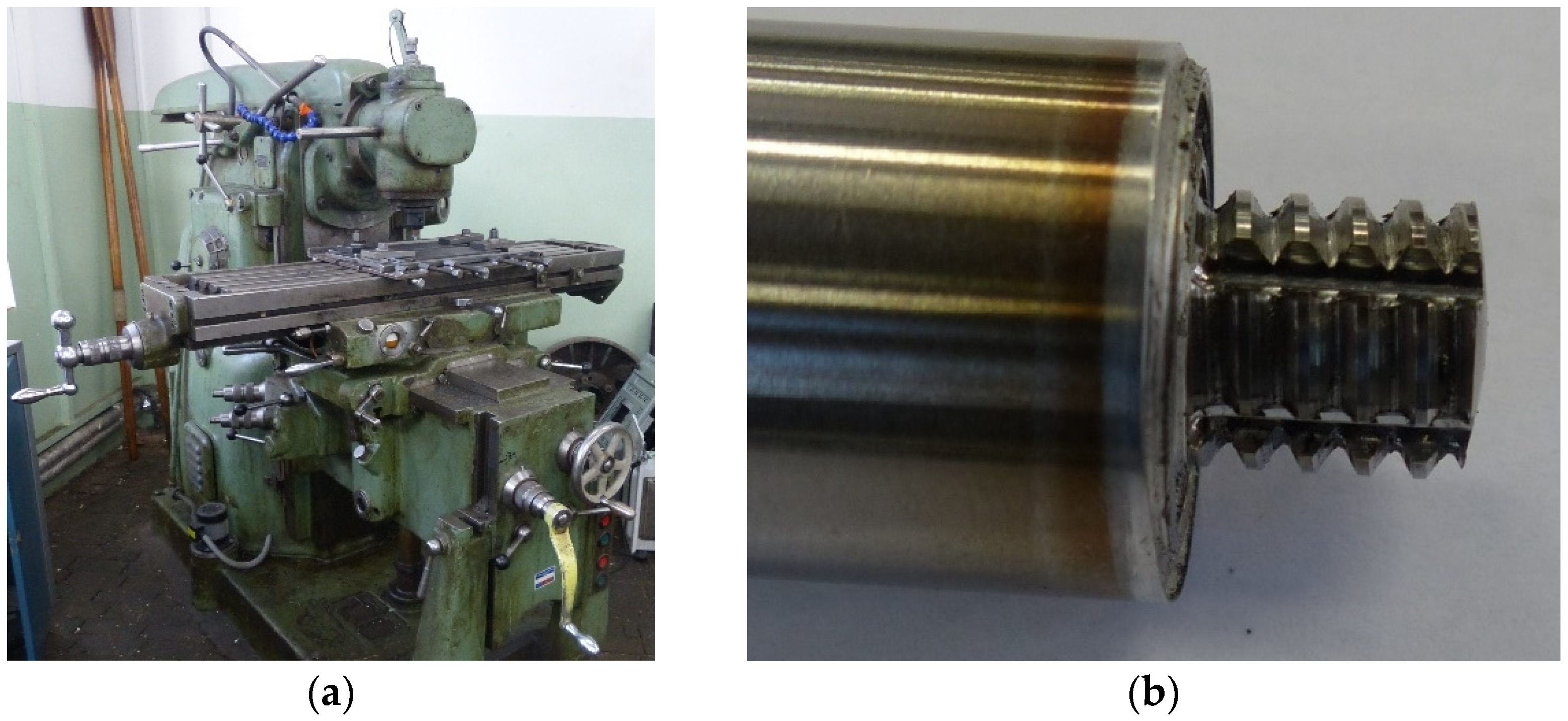
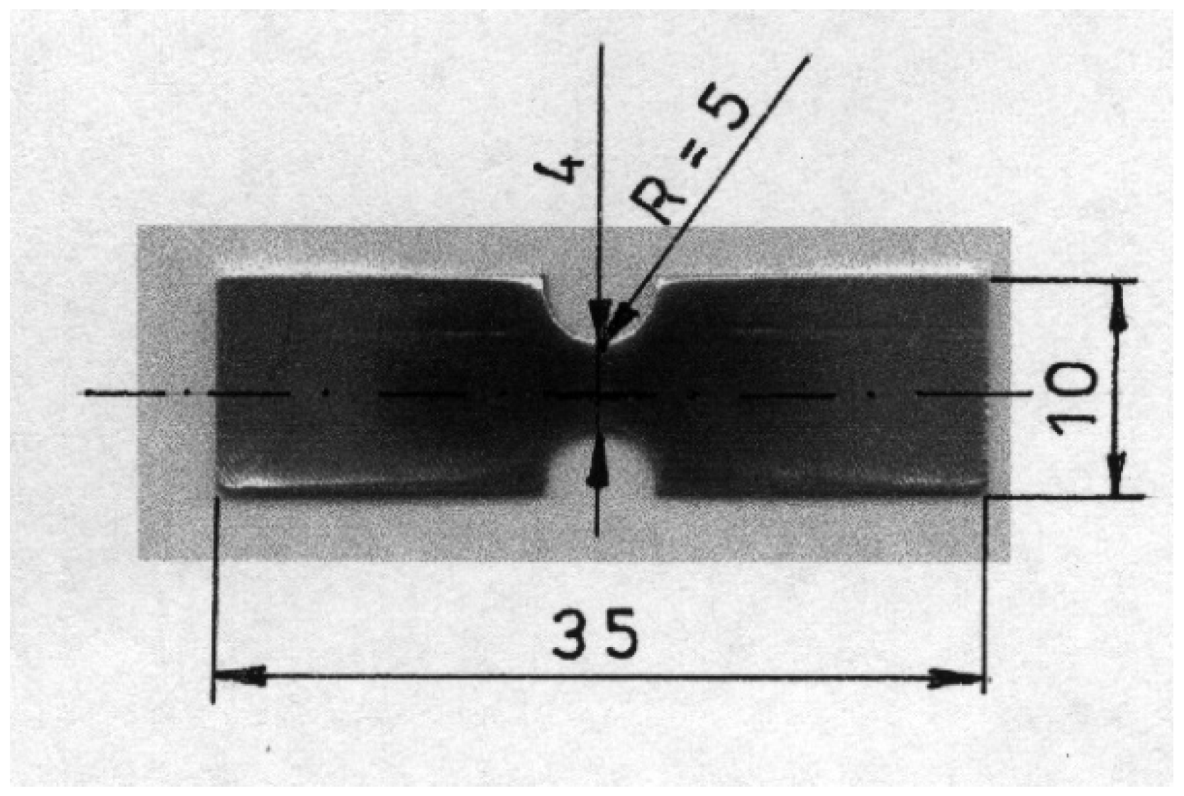
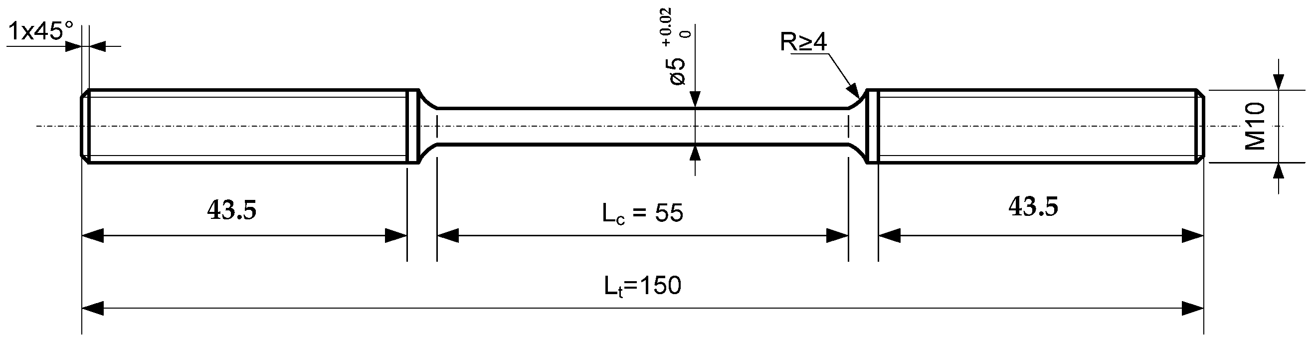
2. Materials and Methods
3. Results
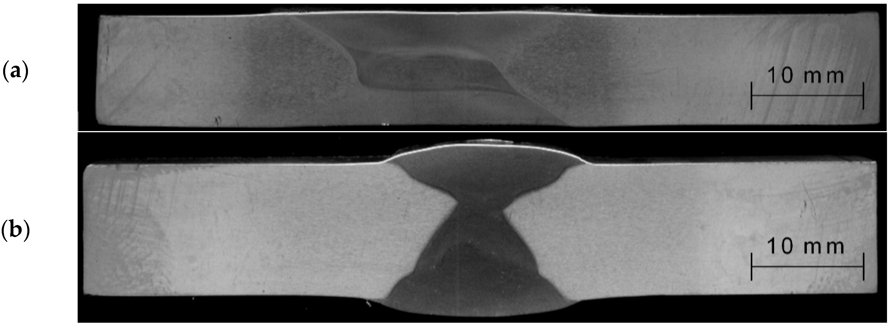
- Plastic deformations;
- The formation of micro-voids and micro-cracks;
- Joining micro-cracks and micro-voids;
- Crack propagation until material failure.
4. Conclusions
- -
- Small precipitates (up to 1 μm) arranged evenly in the matrix and located close to each other can be cut by dislocations, causing plane slippage. Micro-cracks can grow along the slip line, affecting micro-cracks development. Growing, micro-cracks take the shape of a broken line, which increases the surface of the crack, and thus the energy of the cracking process increases.
- -
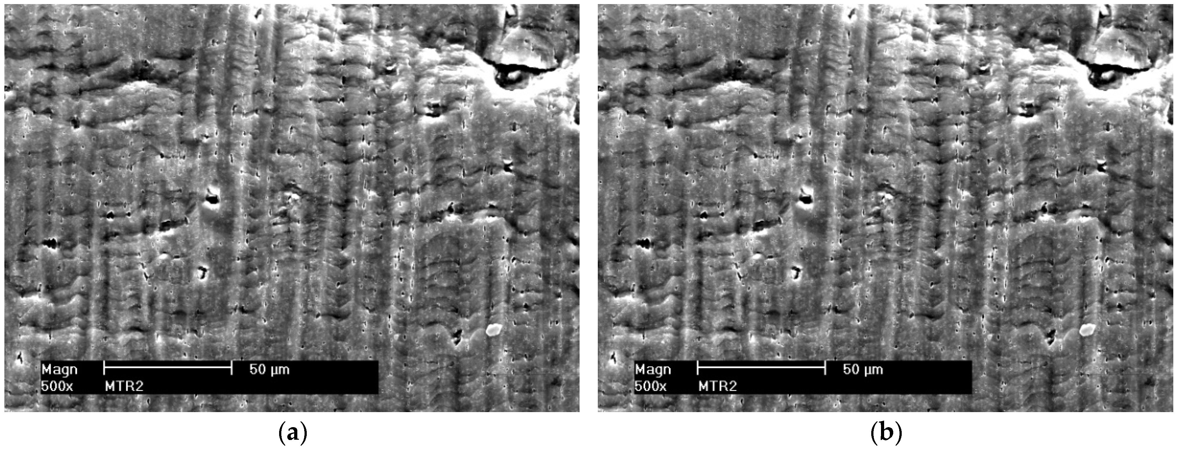
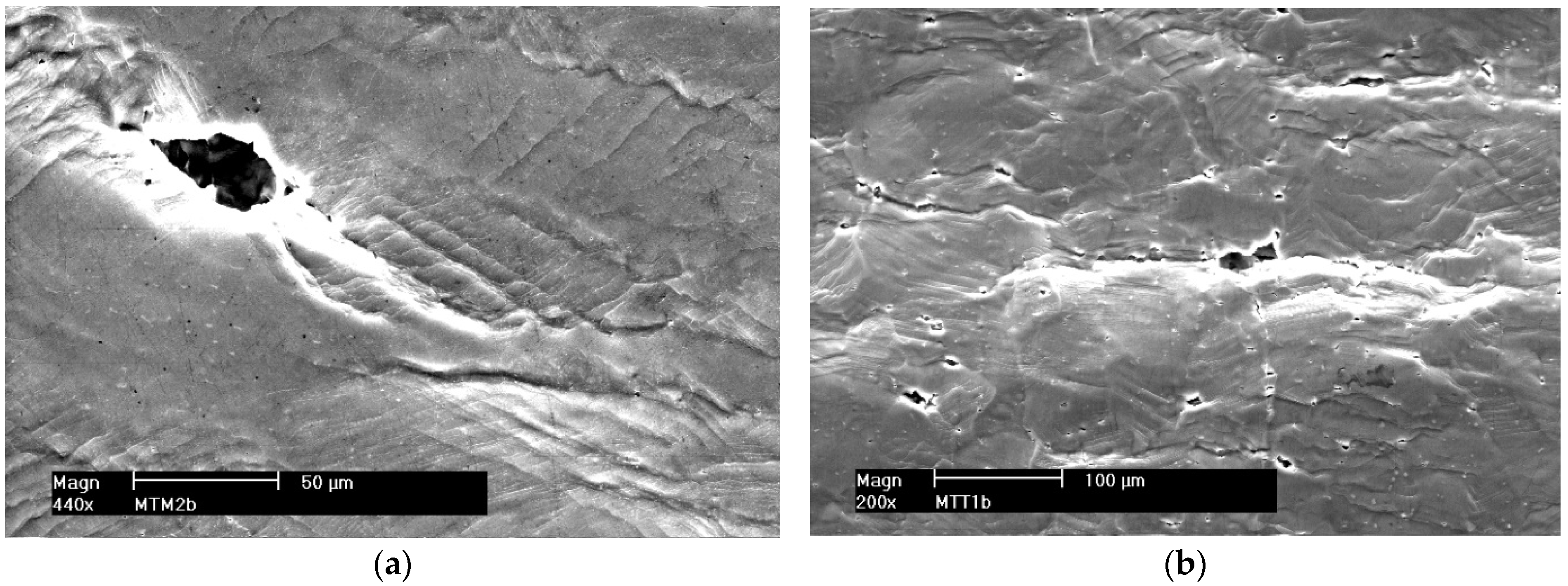
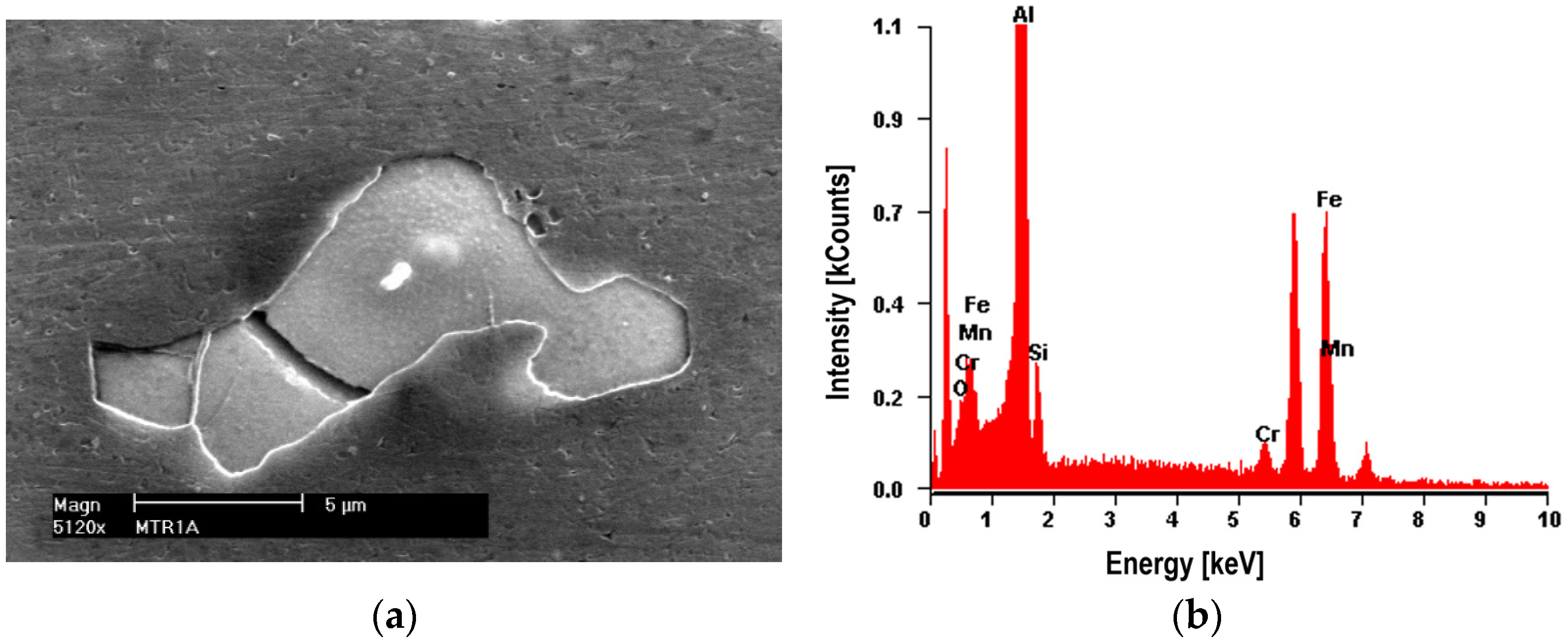
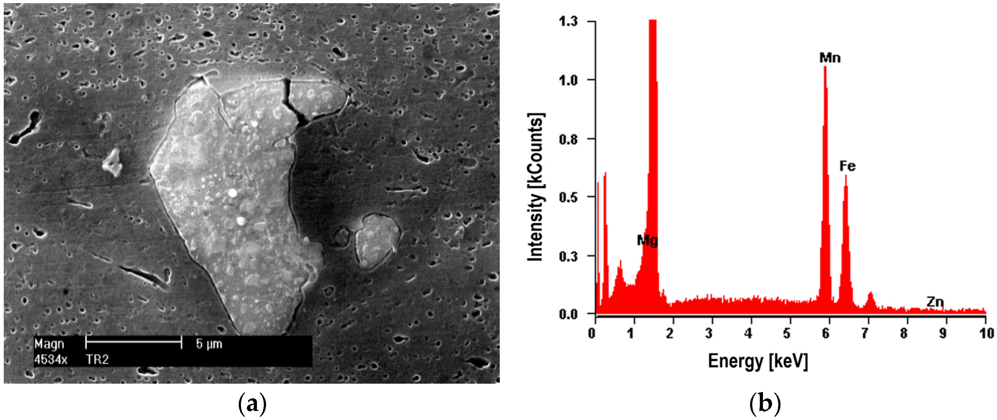
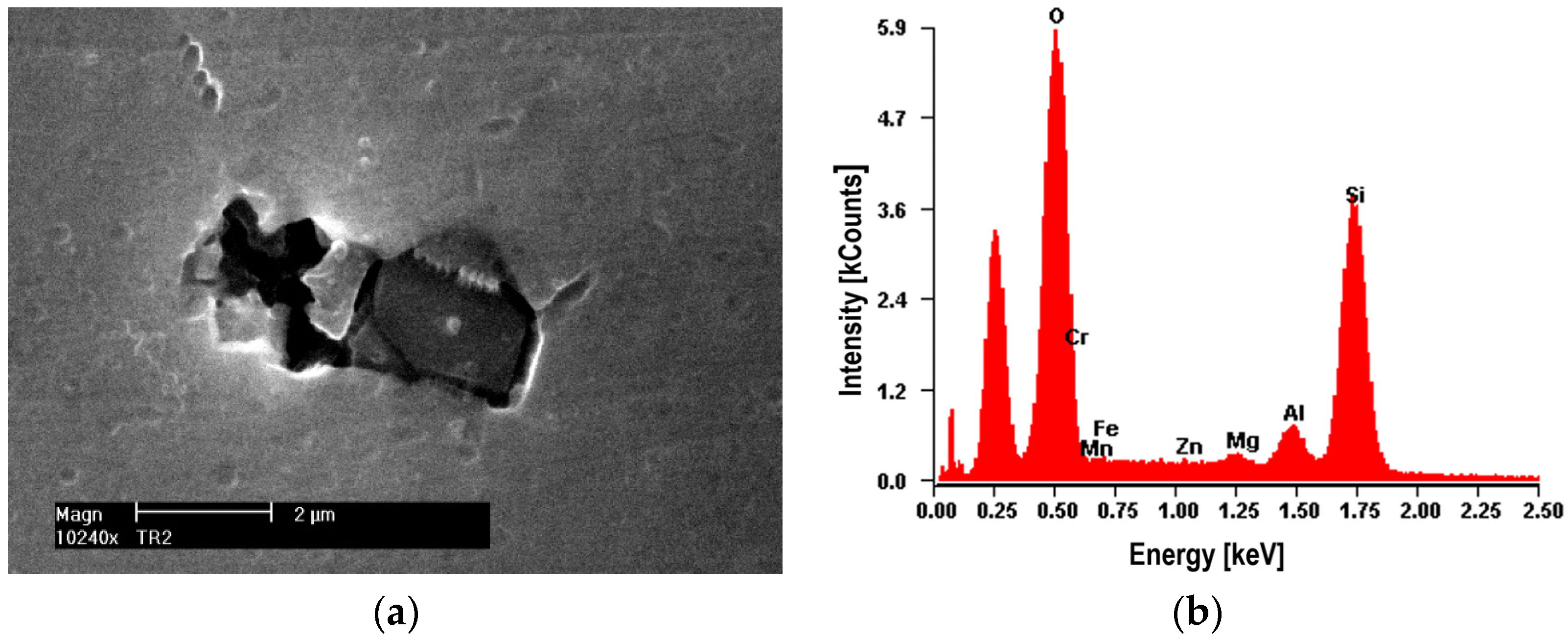
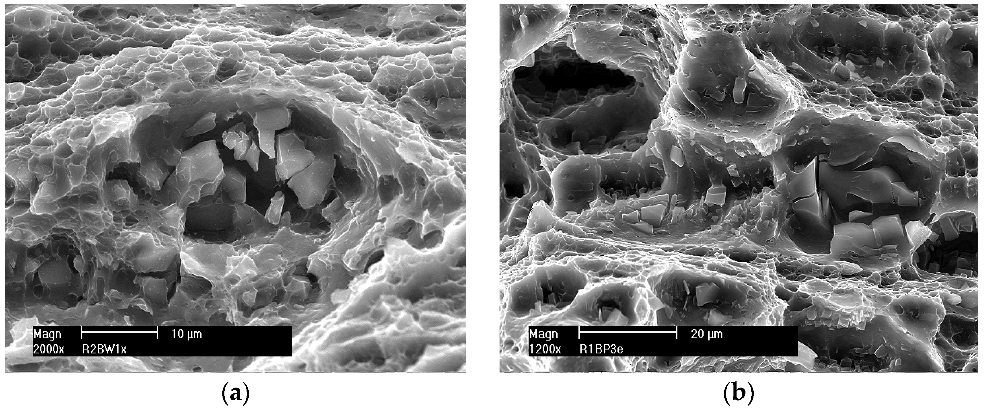
- Large precipitates with dimensions from 2 μm to 25 μm, during the plastic deformation of the material, contribute to the formation of micro-voids. These precipitates occur both in native materials and in bonded joints. The results of chemical microanalysis of the precipitates (EDS) showed that they are formed on the basis of iron or silicon. Therefore, it seems advisable to strive to reduce the content of these elements in technical Al-Mg alloys.
- -
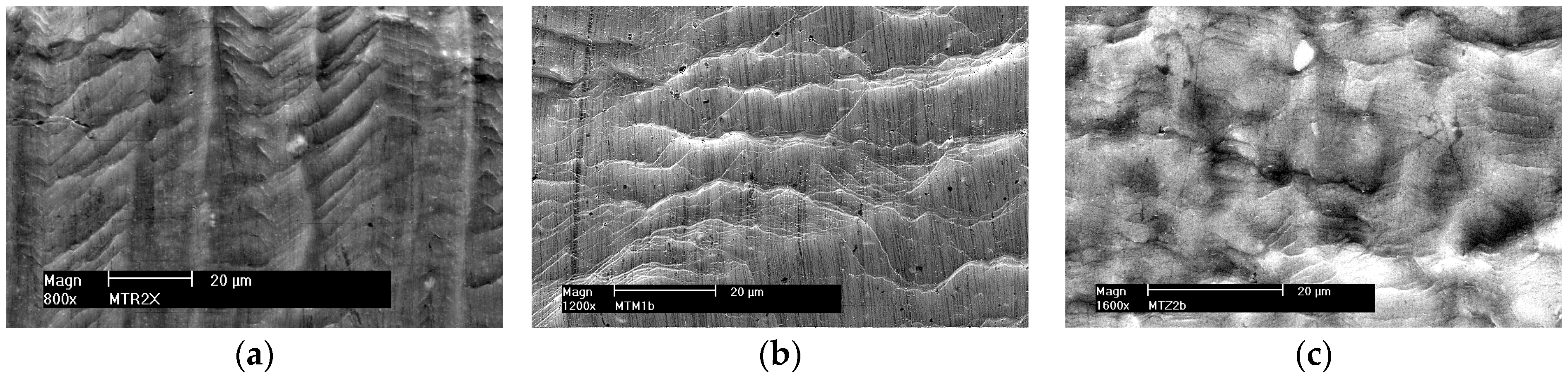
- In base materials (5059 and 5083) and their FSW joints, evenly distributed precipitates and fine-grained structures cause the growth of micro-cracks along the broken line.
- -
- In MIG welds, unevenly distributed precipitates in the structure and clusters of precipitates can be avoided by dislocations that bend and the slip changes its character to wavy. Micro-crack development is easier due to the coarse-grained structure and follows wavy slip lines.
- -
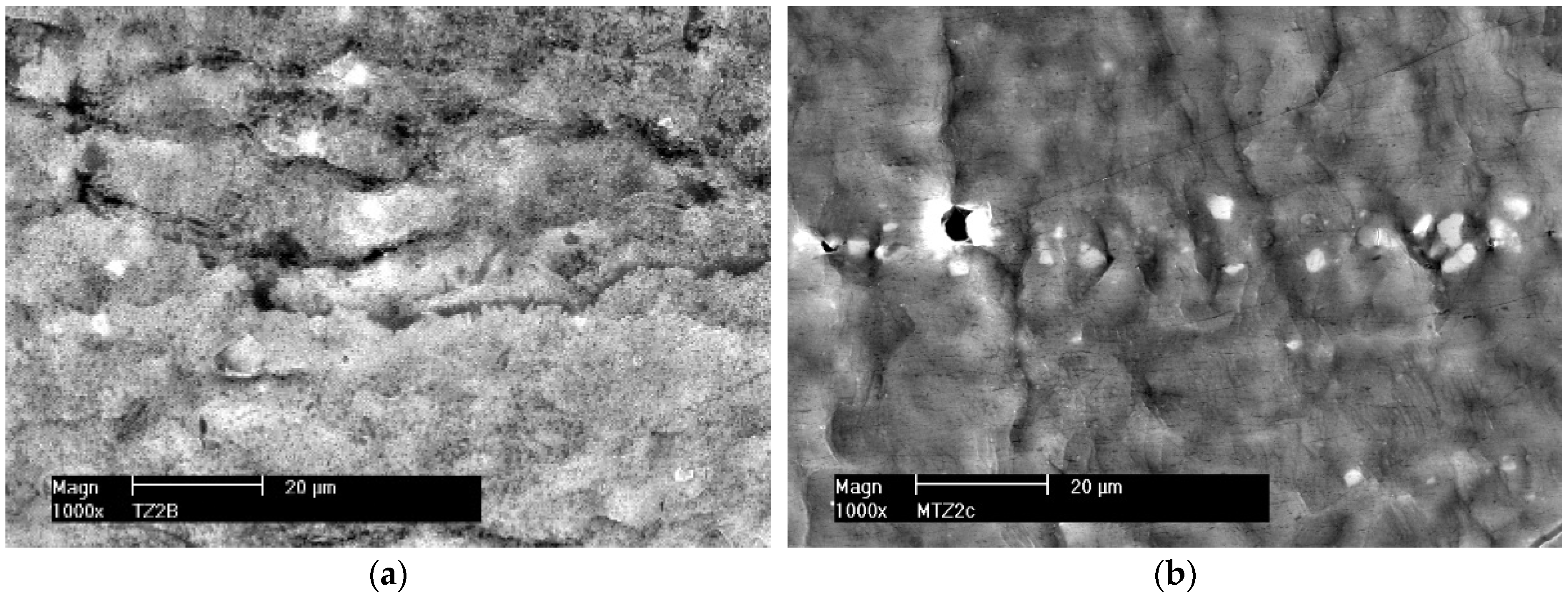
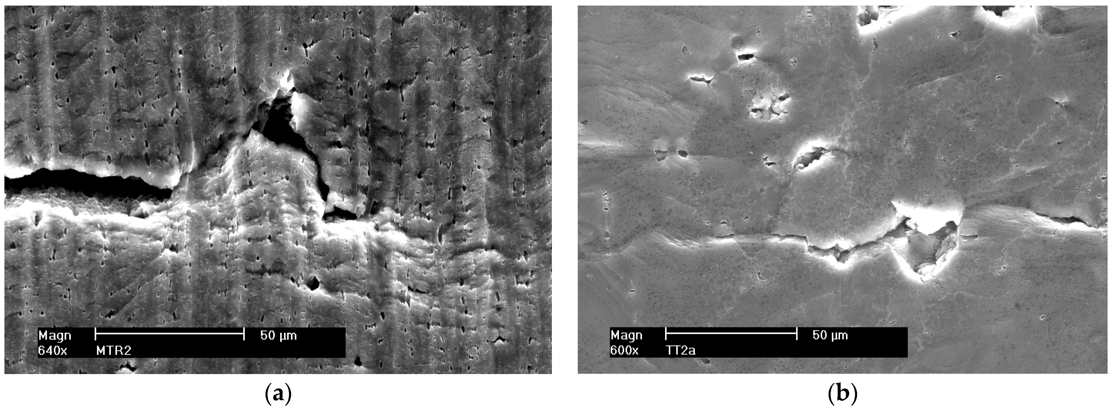
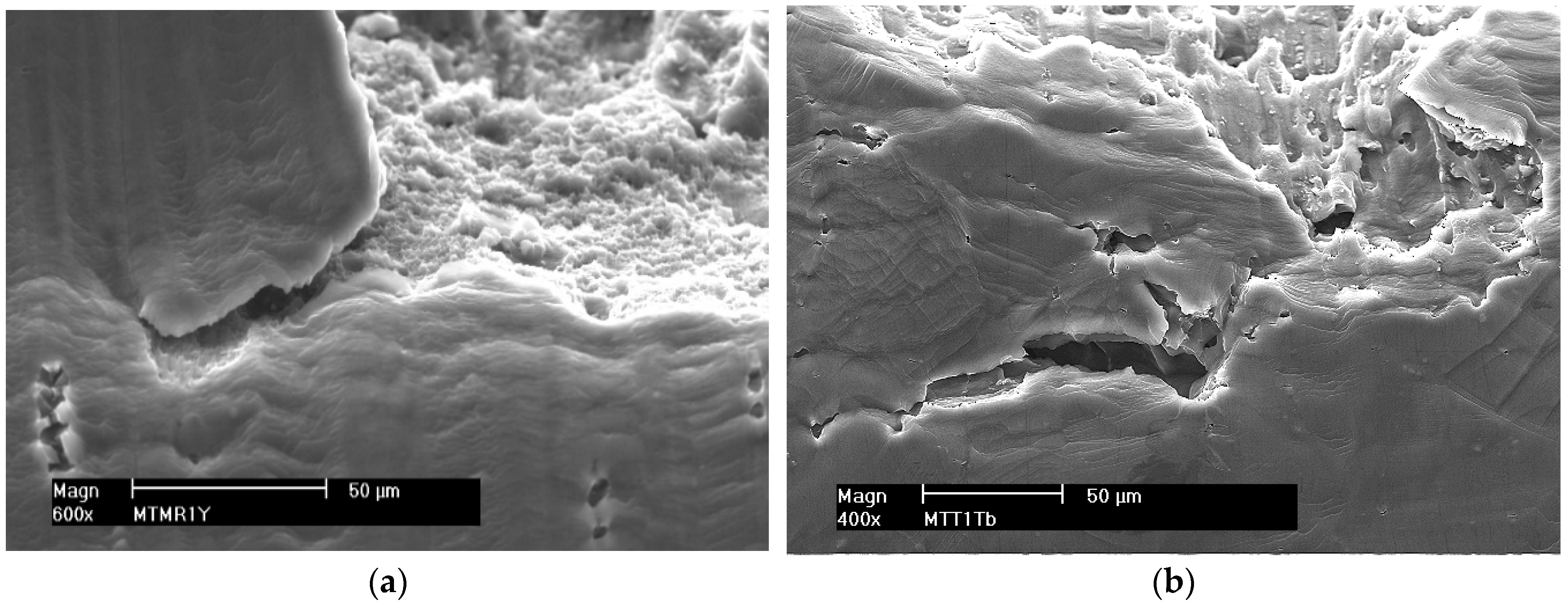
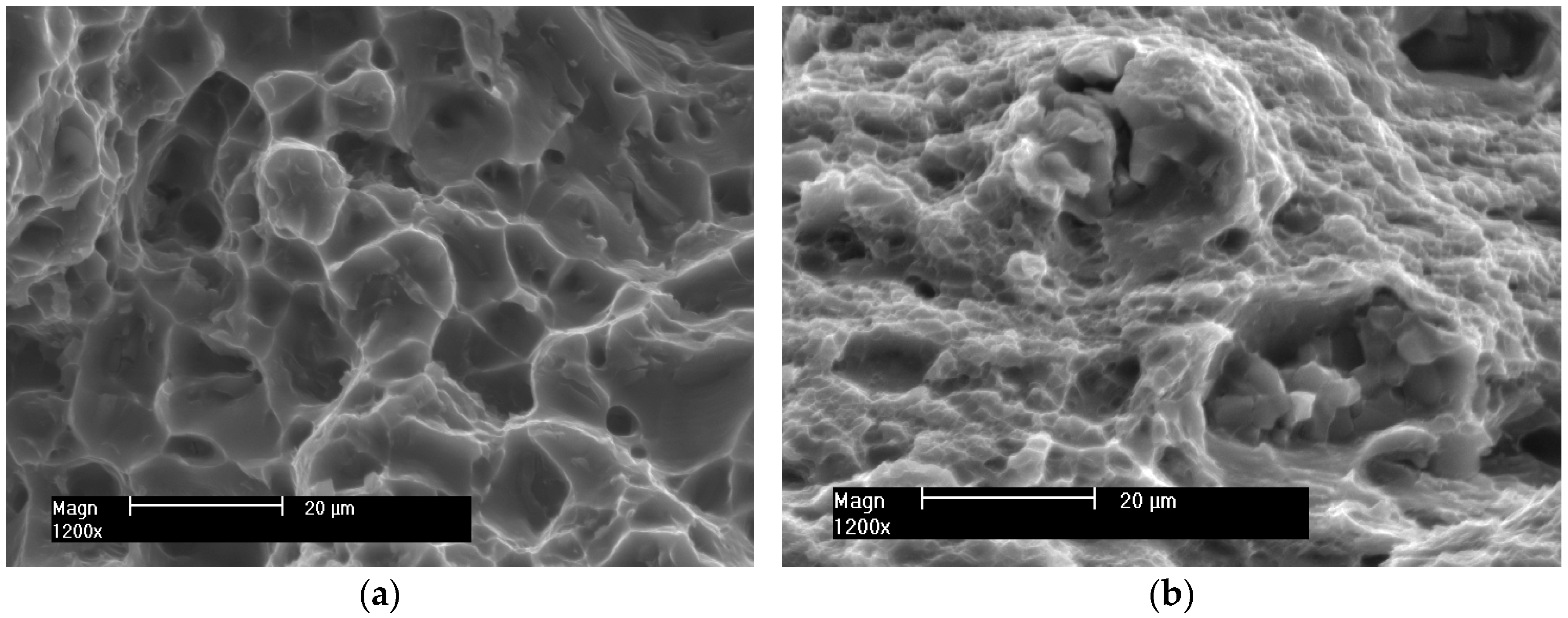
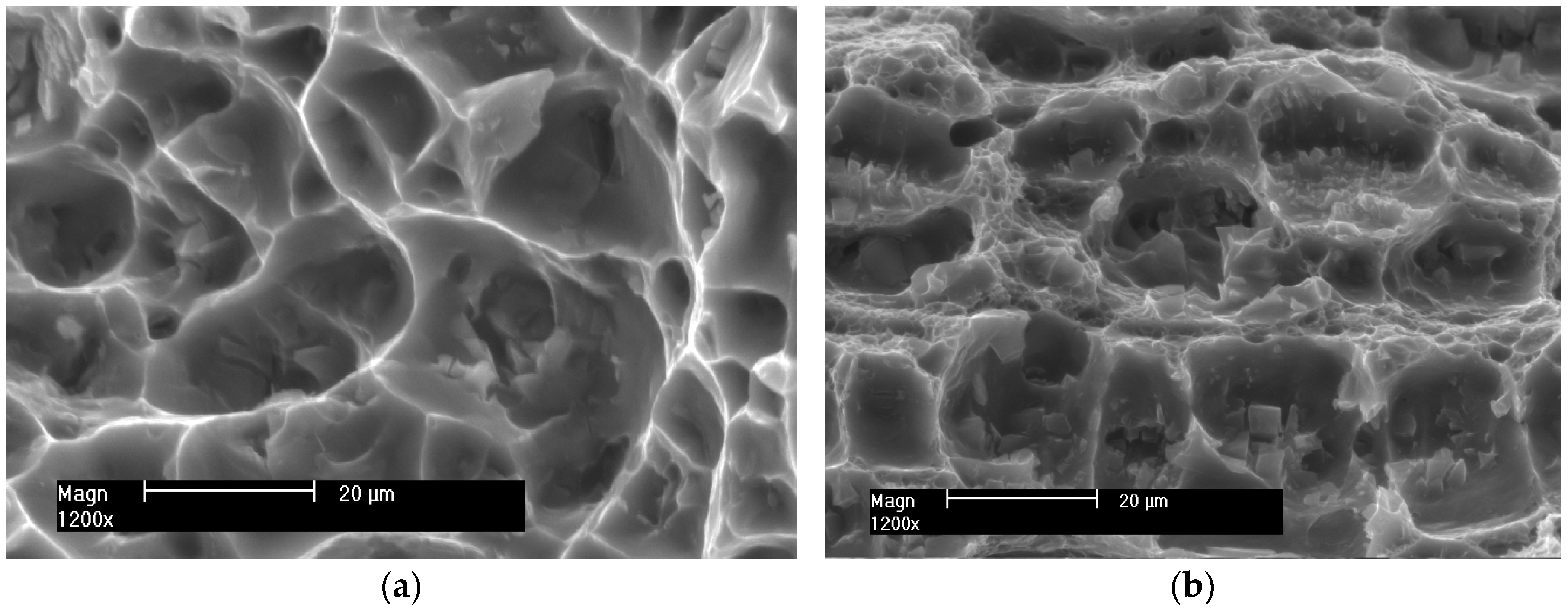
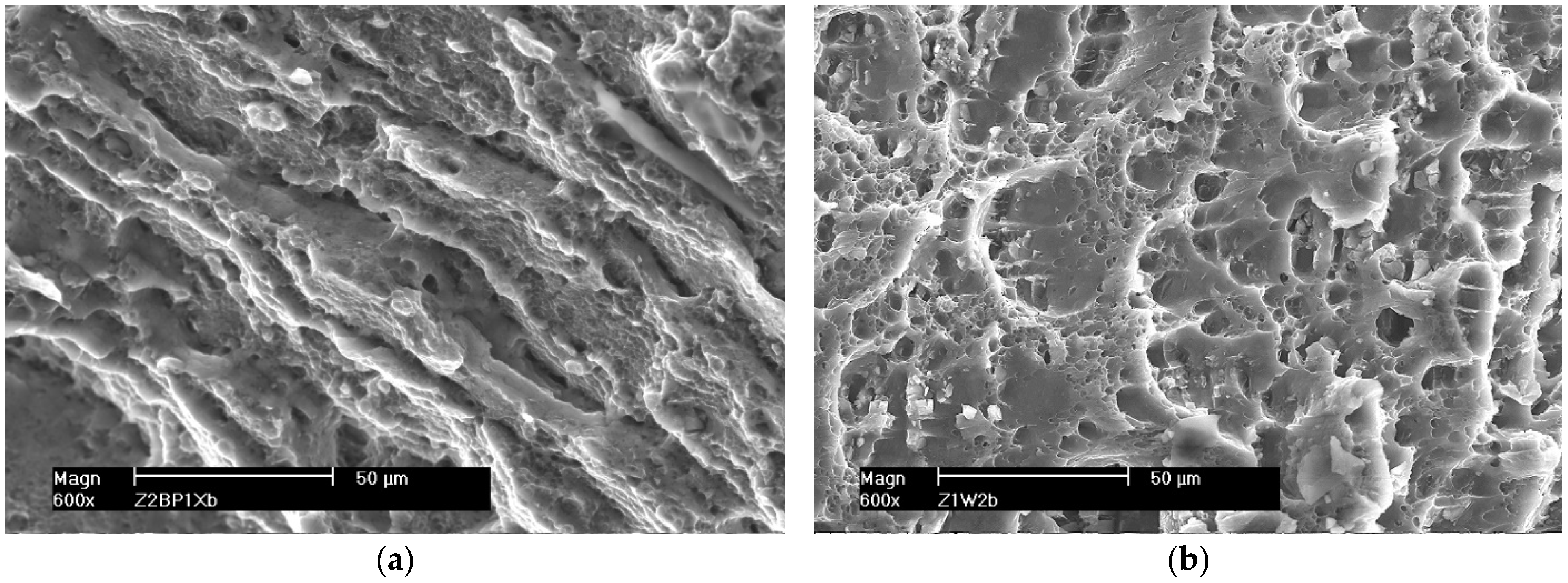
- Micrographs of fractures of all investigated samples after the SSRT allow us to conclude that the cracking mechanism was trans-crystalline ductile.
- -
- In the case of MIG welded joints, the fracture surfaces are highly developed, but there are also relatively large craters that indicate the non-uniformity of the weld structure. This inhomogeneity may be caused by the presence of grains of different sizes and intermetallic phases. These phases occur both in the form of single precipitates as well as a grid on grain boundaries. Numerous cracked intermetallic phases are visible in the wells, which probably initiated the cracking process of the material as a result of the load.
- -
- In the case of samples from base materials of the tested alloys and their joints welded by the FSW method, smaller crater sizes were observed, which suggests smaller grain sizes compared to MIG welds. In the samples welded by the FSW method, no cracked intercrystalline phases were observed at the bottom of the wells. The crack boundaries formed parallel bands characteristic of the material deformed thermoplastically by the welding tool.
- -
- The size of the elevations and depressions on the fracture surfaces depends mainly on the size of the grains and the dispersion of the precipitates. The void formation is easier when particle sizes are larger and the decohesion of interfacial boundaries occurs due to large local deformation around these micro-voids. As the plastic deformation increases, micro-cracks develop and merge into a major crack. After reaching a critical dimension, it develops rapidly, causing the destruction of the material.
Author Contributions
Funding
Institutional Review Board Statement
Informed Consent Statement
Data Availability Statement
Conflicts of Interest
References
- Dudzik, K.; Czechowski, M. Analysis of possible shipbuilding application of Friction Stir Welding (FSW) method to joining elements made of AlZn5Mg1 alloy. Pol. Marit. Res. 2009, 16, 38–40. [Google Scholar] [CrossRef] [Green Version]
- Ferraris, S.; Volpone, L.M. Aluminium alloys in third millennium shipbuilding: Materials, technologies, perspectives. In Proceedings of the Fifth International Forum on Aluminium Ships, Tokyo, Japan, 11–13 October 2005. [Google Scholar]
- Jurczak, W. Damage and Corrosion Diagnostics of Welded Light Alloys Ship Constructions. Solid State Phenom. 2013, 16, 20–28. [Google Scholar] [CrossRef]
- Czechowski, M. Low-cycle fatigue of friction stir welded Al-Mg alloys. J. Mater. Process. Technol. 2005, 164–165, 1001–1006. [Google Scholar] [CrossRef]
- Li, W.; Wu, M.; Xiao, D.; Huang, L.; Liu, W.; Tang, S. Effect of Rolling Temperature on Microstructure and Properties of Al-Mg-Li Alloy. Materials 2022, 15, 7517. [Google Scholar] [CrossRef] [PubMed]
- Stoliara, I.A.; Shepelevicha, V.G.; Wendlerb, E.; Tashlykova-Bushkevichc, I.I. Effect of Lithium on the Structural-Phase State of Rapidly Solidified Al–Mg–Li Alloy During Heat Treatment. J. Surf. Investig. X-ray Synchrotron Neutron Tech. 2021, 15, 752–758. [Google Scholar] [CrossRef]
- Kumar, N.; Mishra, R.S. Thermal stability of friction stir processed ultrafine grained Al\Mg\Sc alloy. Mater. Charact. 2012, 74, 1–10. [Google Scholar] [CrossRef]
- Tong, M.; Jiang, F.; Wang, H.; Jiang, J.; Wu, M.; Tang, Z. The evolutions of flow stress and microstructure of Al-Mg-Mn-Sc-Zr alloy at elevated temperatures. Mater. Charact. 2021, 182, 111560. [Google Scholar] [CrossRef]
- Li, X.; Liu, Y.; Zhou, Z. Grain refinement and performance enhancement of laser powder bed fusion in-situ processed Al-Mg alloy modified by ScH3 and ZrH2. Mater. Charact. 2022, 190, 112068. [Google Scholar] [CrossRef]
- Ekubaru, Y.; Gokcekaya, O.; Nakano, T. Effects of Scanning Strategy on the Microstructure and Mechanical Properties of Sc-Zr-Modified Al–Mg Alloy Manufactured by Laser Powder Bed Fusion. Crystals 2022, 12, 1348. [Google Scholar] [CrossRef]
- Nokhrin, A.; Shadrina, I.; Chuvil’deev, V.; Kopylov, V. Study of Structure and Mechanical Properties of Fine-Grained Aluminium Alloys Al-0.6wt.%Mg-Zr-Sc with Ratio Zr:Sc = 1.5 Obtained by Cold Drawing. Materials 2019, 12, 316. [Google Scholar] [CrossRef] [Green Version]
- Abrami, M.B.; Tocci, M.; Gelfi, M.; Pola, A. High Temperature Mechanical Properties of AlMgScZr Alloy Produced by Laser Powder Bed Fusion. Procedia Struct. Integr. 2022, 42, 838–846. [Google Scholar] [CrossRef]
- Chen, H.; Chen, Z.; Ji, G.; Zhong, S.; Wang, H.; Borb’ely, A.; Ke, Y.; Br´echet, Y. Experimental and modelling assessment of ductility in a precipitation hardening AlMgScZr alloy. Int. J. Plast. 2021, 139, 102971. [Google Scholar] [CrossRef]
- Dudzik, K.; Jurczak, W. Influence of friction stir welding (FSW) on mechanical and corrosion properties of AW-7020M and AW-7020 alloys. Pol. Marit. Res. 2016, 23, 86–90. [Google Scholar] [CrossRef] [Green Version]
- Lahti, K. FSW—Possibilities in shipbuilding. Svetsaren 2003, 58, 6–8. [Google Scholar] [CrossRef]
- Kim, S.; Lee, C.L.; Kimb, S.J. Fatigue crack propagation behavior of friction stir welded 5083-H32 and 6061-T651 aluminium alloys. Mater. Sci. Eng. 2008, 478, 56–64. [Google Scholar] [CrossRef]
- Niu, P.; Li, W.; Chen, Y.; Liu, Q.; Chen, D. Base material location dependence of corrosion response in friction-stir-welded dissimilar 2024-to-5083 aluminium alloy joints. Trans. Nonferrous Met. Soc. China 2022, 32, 2164–2176. [Google Scholar] [CrossRef]
- Matsuda, T.; Ogaki, T.; Hayashi, K.; Iwamoto, C.; Nozawa, T.; Ohata, M.; Hirose, A. Fracture dominant in friction stir spot welded joint between 6061 aluminium alloy and galvannealed steel based on microscale tensile testing. Mater. Des. 2022, 213, 110344. [Google Scholar] [CrossRef]
- Picot, F.; Gueydan, A.; Martinez, M.; Moisy, F.; Hug, E. A Correlation between the Ultimate Shear Stress and the Thickness Affected by Intermetallic Compounds in Friction Stir Welding of Dissimilar Aluminium Alloy–Stainless Steel Joints. Metals 2018, 8, 179. [Google Scholar] [CrossRef] [Green Version]
- Chen, Y.; Liu, C.; Liu, G. Study on the Joining of Titanium and Aluminium Dissimilar Alloys by Friction Stir Welding. Open Mater. Sci. J. 2011, 5, 256–261. [Google Scholar] [CrossRef]
- Shanavas, S.; Dhas, J.E.R. Weldability of AA 5052 H32 aluminium alloy by TIG welding and FSW process—A comparative study. Mater. Sci. Eng. 2017, 247, 012016. [Google Scholar] [CrossRef]
- Kalashnikova, T.; Chumaevskii, A.; Kalashnikov, K.; Fortuna, S.; Kolubaev, E.; Tarasov, S. Microstructural Analysis of Friction Stir Butt Welded Al-Mg-Sc-Zr Alloy Heavy Gauge Sheets. Metals 2020, 10, 806. [Google Scholar] [CrossRef]
- Bagheri, B.; Alizadeh, M.; Mirsalehi, S.E.; Shamsipur, A.; Abdollahzadeh, A. Nanoparticles Addition in AA2024 Aluminium/Pure Copper Plate: FSSW Approach, Microstructure Evolution, Texture Study, and Mechanical Properties. JOM 2022, 74, 4420–4433. [Google Scholar] [CrossRef]
- Bagheri, B.; Abdollahzadeh, A.; Shamsipur, A. A different attempt to analysis friction stir spot welding of AA5083-copper alloys. Mater. Sci. Technol. 2023, 1–7. [Google Scholar] [CrossRef]
- Vaneghi, A.H.; Bagheri, B.; Shamsipur, A.; Mirsalehi, S.E.; Abdollahzadeh, A. Investigations into the formation of intermetallic compounds during pinless friction stir spot welding of AA2024-Zn-pure copper dissimilar joints. Weld. World 2022, 66, 2351–2369. [Google Scholar] [CrossRef]
- Suresh, S.; Natarajan, E.; Franz, G.; Rajesh, S. Differentiation in the SiC Filler Size Effect in the Mechanical and Tribological Properties of Friction-Spot-Welded AA5083-H116 Alloy. Fibers 2022, 10, 109. [Google Scholar] [CrossRef]
- Liu, X.C.; Wu, C.S.; Padhy, G.K. Improved weld macrosection, microstructure and mechanical properties of 2024Al-T4 buttjoints in ultrasonic vibration enhanced friction stir welding. Sci. Technol. Weld. Join. 2015, 20, 345–352. [Google Scholar] [CrossRef]
- Abbasi, M.; Bagheri, B.; Sharifi, F. Simulation and experimental study of dynamic recrystallization process during friction stir vibration welding of magnesium alloys. Trans. Nonferrous Met. Soc. China 2021, 31, 2626–2650. [Google Scholar] [CrossRef]
- Kim, S.; Hong, J.; Joo, Y.; Kang, M. Synergistic effect of SiC nano-reinforcement and vibrator assistance in micro-friction stir welding of dissimilar AA5052-H32/AA6061-T6. J. Manuf. Process. 2022, 82, 860–869. [Google Scholar] [CrossRef]
- Fouladi, S.; Ghasemi, A.H.; Abbasi, M.; Abedini, M.; Khorasani, A.M.; Gibson, I. The Effect of Vibration during Friction Stir Welding on Corrosion Behavior, Mechanical Properties, and Machining Characteristics of Stir Zone. Metals 2017, 7, 421. [Google Scholar] [CrossRef]
- Mirian Mehrian, S.S.; Rahsepar, M.; Khodabakhshi, F.; Gerlich, A.P. Effects of friction stir processing on the microstructure, mechanical and corrosion behaviors of an aluminium-magnesium alloy. Surf. Coat. Technol. 2021, 405, 126647. [Google Scholar] [CrossRef]
- Liyakat, N.A.; Veeman, D. Improvement of mechanical and microstructural properties of AA 5052-H32 TIG weldment using friction stir processing approach. J. Mater. Res. Technol. 2022, 19, 332–344. [Google Scholar] [CrossRef]
- Lall, A.; Bowen, P.; Rabiei, A. A numerical and experimental approach to compare the effect of sample thickness in small in-situ SEM and large ex-situ tensile testing in Alloy 709. Mater. Charact. 2022, 184, 111614. [Google Scholar] [CrossRef]
- Li, H.; Takata, N.; Kobashi, M.; Serizawa, A. In Situ Scanning Electron Microscopy Observation of Crack Initiation and Propagation in Hydroxide Films Formed by Steam Coating on Aluminium-Alloy Sheets. Materials 2020, 13, 1238. [Google Scholar] [CrossRef] [Green Version]
- Guercio, G.D.e.l.; McCartney, D.G.; Aboulkhair, N.T.; Robertson, S.; Maclachlan, R.; Tuck, C.; Simonelli, M. Cracking behaviour of high-strength AA2024 aluminium alloy produced by Laser Powder Bed Fusion. Addit. Manuf. 2022, 54, 102776. [Google Scholar] [CrossRef]
- Aboura, Y.; Garner, A.J.; Euesden, R.; Barrett, Z.; Engel, C.; Holroyd, N.J.H.; Prangnell, P.B.; Burnett, T.L. Understanding the environmentally assisted cracking (EAC) initiation and propagation of new generation 7xxx alloys using slow strain rate testing. Corros. Sci. 2022, 199, 110161. [Google Scholar] [CrossRef]
- Wang, S.; Luo, B.; Bai, Z.; He, C.; Tan, S.; Jiang, G. Effect of Zn/Mg Ratios on Microstructure and Stress Corrosion Cracking of 7005 Alloy. Materials 2019, 12, 285. [Google Scholar] [CrossRef] [Green Version]
- Li, M.; Shi, Z.; Wu, X.; Wang, H.; Liu, Y. Study of the Microstructure and Crack Evolution Behavior of Al-5Fe-1.5Er Alloy. Materials 2019, 12, 172. [Google Scholar] [CrossRef] [Green Version]
- Holroyd, N.J.H.; Burnettc, T.L.; Seifia, M.; Lewandowski, J.J. Improved understanding of environment-induced cracking (EIC) of sensitized 5XXX series aluminium alloys. Mater. Sci. Eng. 2017, 682, 613–621. [Google Scholar] [CrossRef]
- Popovic, M.; Romhanji, E. Stress corrosion cracking susceptibility of Al–Mg alloy sheet with high Mg content. J. Mater. Process. Technol. 2002, 125–126, 275–280. [Google Scholar] [CrossRef]
- Torzewski, J.; Grzelak, K.; Wachowski, M.; Kosturek, R. Microstructure and Low Cycle Fatigue Properties of AA5083 H111 Friction Stir Welded Joint. Materials 2020, 13, 2381. [Google Scholar] [CrossRef]
- Duan, S.; Wu, D.; Liu, W.; Chen, J.; Wang, T.; Zou, Y. Stress corrosion cracking behavior of friction stir welded 5052-H112 Al–Mg alloy. Vacuum 2020, 176, 109299. [Google Scholar] [CrossRef]
- Davis, J.R. Aluminium and Aluminium Alloys; ASM International: Materials Park, OH, USA, 1998. [Google Scholar]
- Wyrzykowski, J.W.; Pleszakow, E.; Sieniawski, A. Deformation and Cracking of Metals; WNT: Warsaw, Poland, 1999. (In Polish) [Google Scholar]


| Alloy | Chemical Composition [wt.%] | |||||||||||
|---|---|---|---|---|---|---|---|---|---|---|---|---|
| Si | Fe | Cu | Mn | Mg | Cr | Zn | Ti | Zr | B | Ni | Al | |
| 5059 | 0.037 | 0.09 | 0.01 | 0.76 | 5.41 | 0.003 | 0.57 | 0.024 | 0.11 | 0.01 | 0.004 | bal. |
| 5083 | 0.195 | 0.18 | 0.09 | 0.662 | 4.745 | 0.111 | 0.042 | 0.025 | 0.037 | 0.002 | 0.005 | bal. |
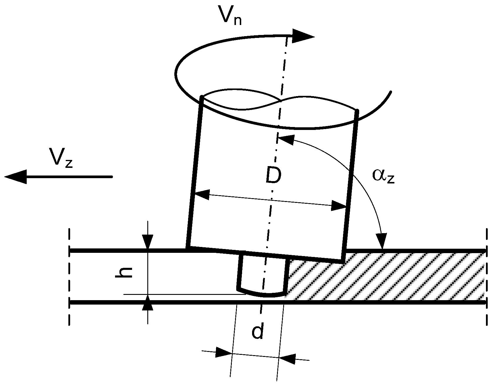
| Tool Dimensions | Angle of Tool Deflection | Mandrel’s Rotary Speed | Welding Speed | ||
|---|---|---|---|---|---|
| D [mm] | d [mm] | h [mm] | αz [°] | Vn [rpm] | Vz [mm/min] |
| 25.0 | 10.0 | 6.0 | 88 | 900 | 140 |
| Alloy | Chemical Composition [wt.%] | |||||||
|---|---|---|---|---|---|---|---|---|
| Mg | Zn | Cu | Si | Fe | Mn | Ti | Al | |
| 5383 | 4.0–5.2 | 0.4 | 0.4 | 0.25 | 0.25 | 0.8 | 0.15 | balance |
| 5183 | 4.86 | 0.001 | 0.001 | 0.04 | 0.12 | 0.64 | 0.006 | balance |
| Alloy | Joining Method | Smax [MPa] | EL [%] | Td [h] |
|---|---|---|---|---|
| 5059 | Native material | 418.4 | 24.0 | 33.0 |
| FSW | 384.8 | 19.8 | 28.9 | |
| MIG | 319.4 | 16.2 | 24.0 | |
| 5083 | Native material | 371.0 | 18.5 | 26.9 |
| FSW | 322.8 | 14.4 | 24.5 | |
| MIG | 303.6 | 11.0 | 15.8 |
Disclaimer/Publisher’s Note: The statements, opinions and data contained in all publications are solely those of the individual author(s) and contributor(s) and not of MDPI and/or the editor(s). MDPI and/or the editor(s) disclaim responsibility for any injury to people or property resulting from any ideas, methods, instructions or products referred to in the content. |
© 2023 by the authors. Licensee MDPI, Basel, Switzerland. This article is an open access article distributed under the terms and conditions of the Creative Commons Attribution (CC BY) license (https://creativecommons.org/licenses/by/4.0/).
Share and Cite
Dudzik, K.; Czechowski, M. The Cracking of Al-Mg Alloys Welded by MIG and FSW under Slow Strain Rating. Materials 2023, 16, 2643. https://doi.org/10.3390/ma16072643
Dudzik K, Czechowski M. The Cracking of Al-Mg Alloys Welded by MIG and FSW under Slow Strain Rating. Materials. 2023; 16(7):2643. https://doi.org/10.3390/ma16072643
Chicago/Turabian StyleDudzik, Krzysztof, and Mirosław Czechowski. 2023. "The Cracking of Al-Mg Alloys Welded by MIG and FSW under Slow Strain Rating" Materials 16, no. 7: 2643. https://doi.org/10.3390/ma16072643