


Investigations for Material Tracing in Selective Laser Sintering: Part ΙΙ: Validation of Modified Polymers as Marking Agents
 ,
,
Abstract
: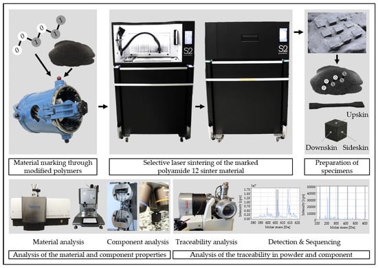
1. Introduction
2. Materials and Methods
2.1. Sinter Material
2.2. Modified Polymer
2.3. Production of the Master Batch
2.4. Particle Analysis
2.5. Classification of Powder Density
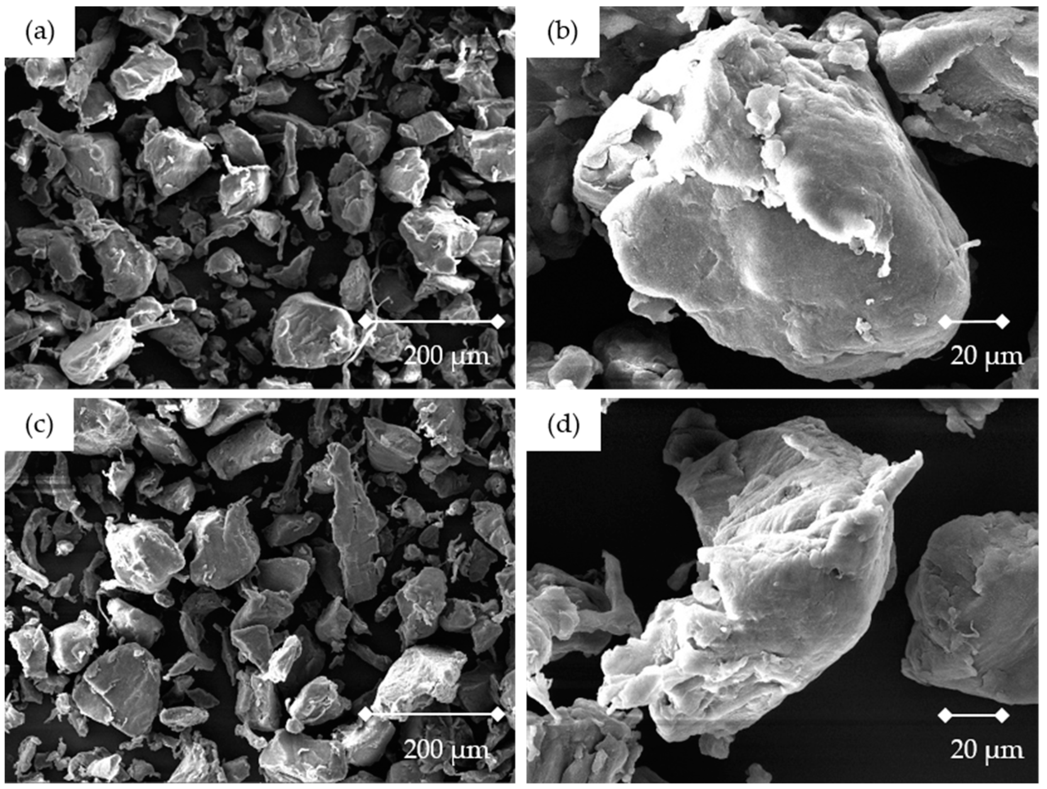
2.6. Scanning Electron Microscope
2.7. Differential Scanning Calometry Testing
2.8. Melt Flow Index Testing
2.9. Mixing Technology
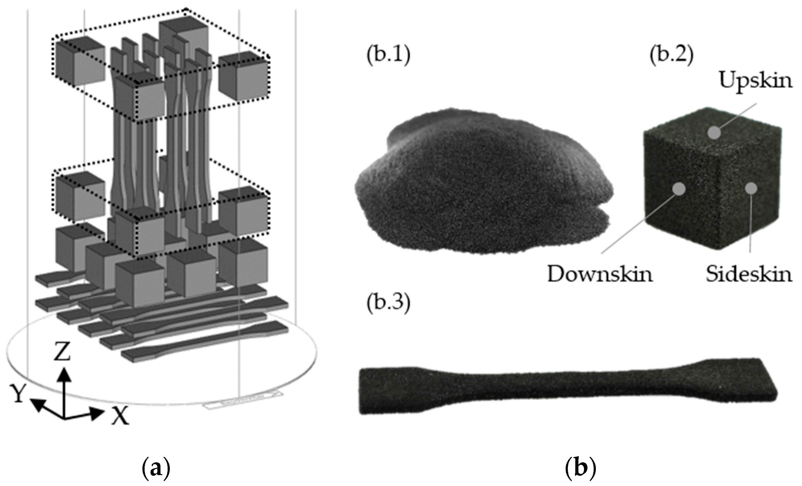
2.10. Selective Laser Sintering Processing
2.11. Tensile Test
2.12. Sinter Density
2.13. Confocal Microscopy
2.14. Tandem Mass Spectroscopy
3. Results
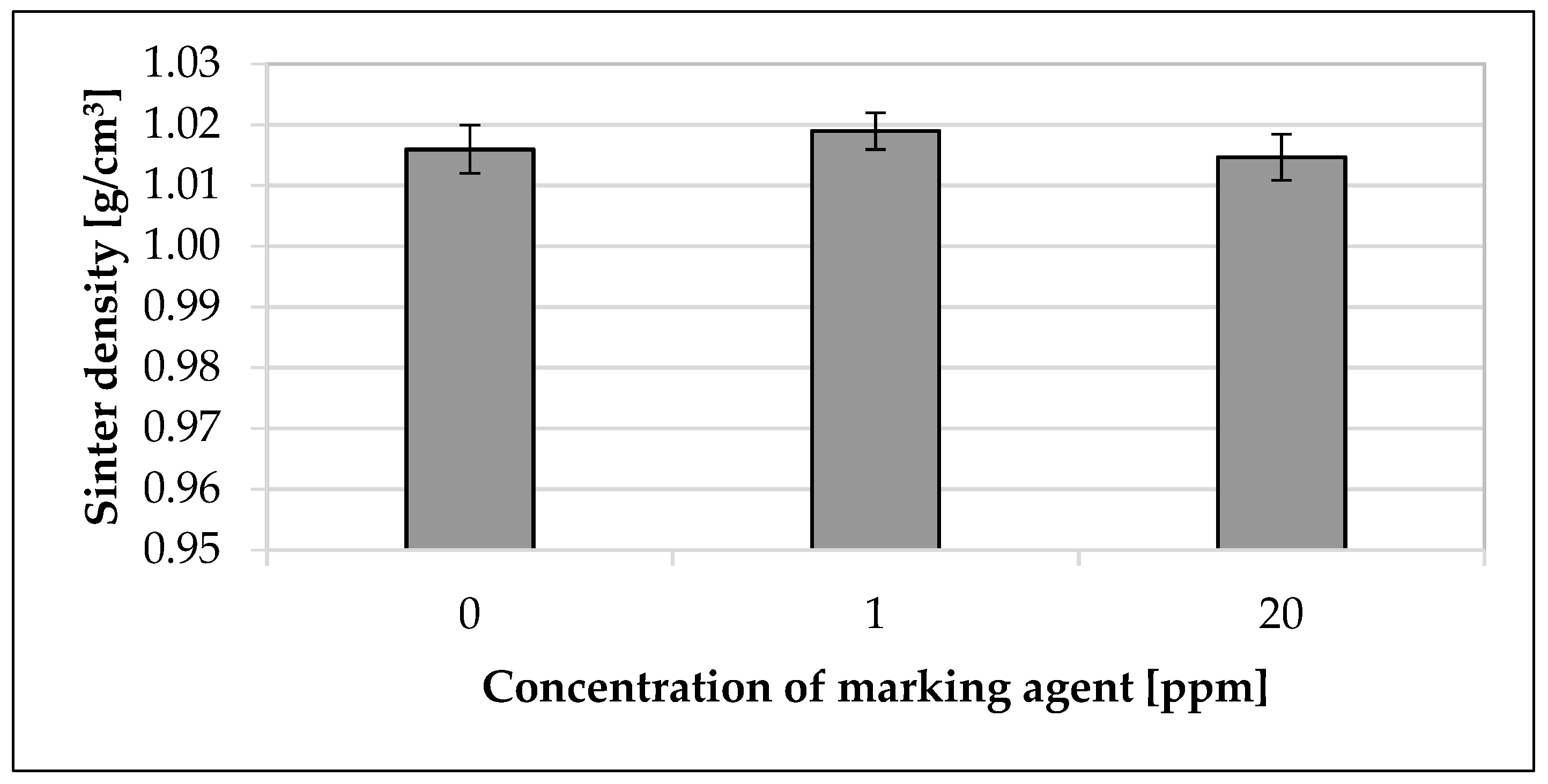
3.1. Influence on the Material Properties
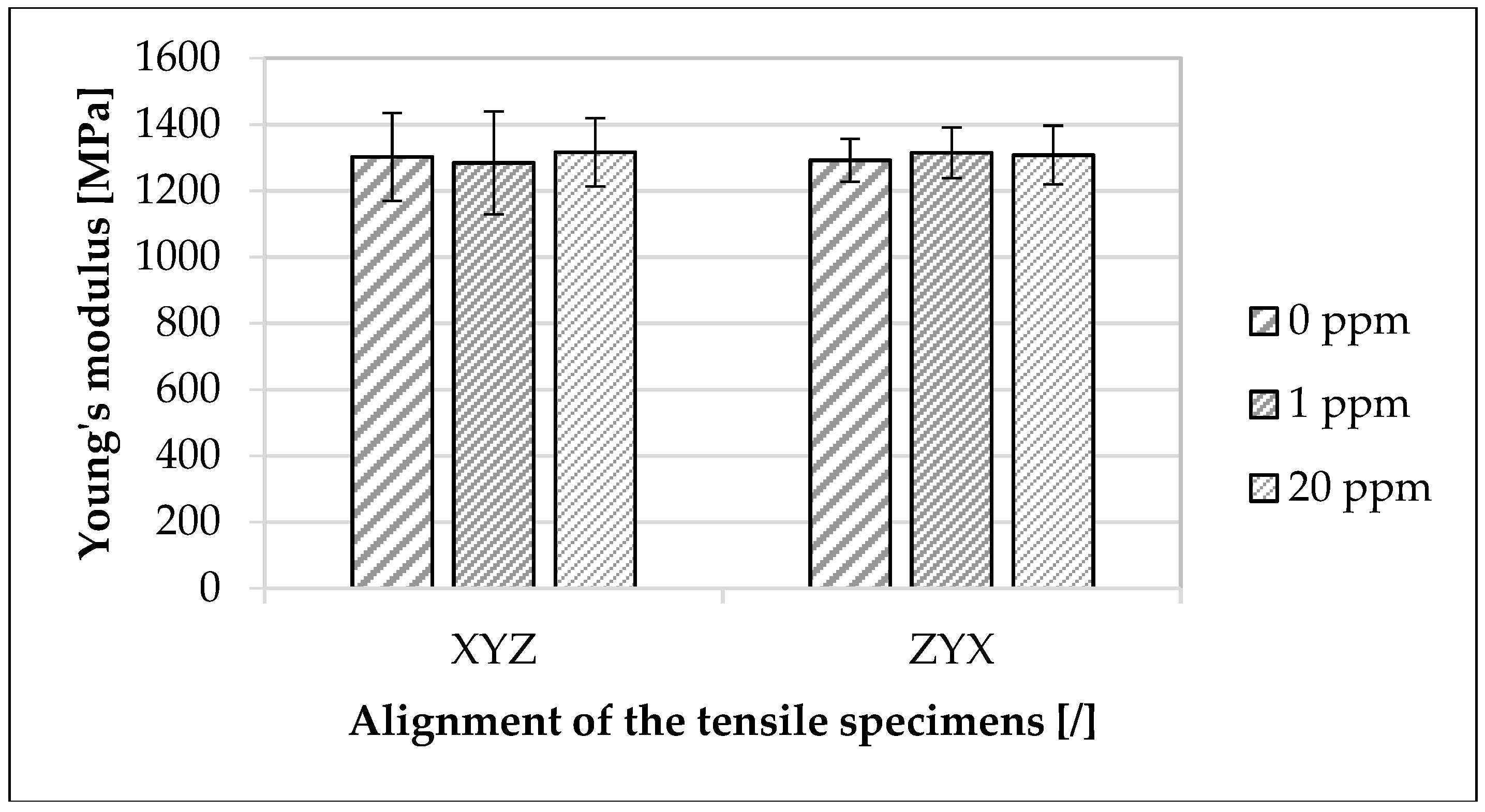
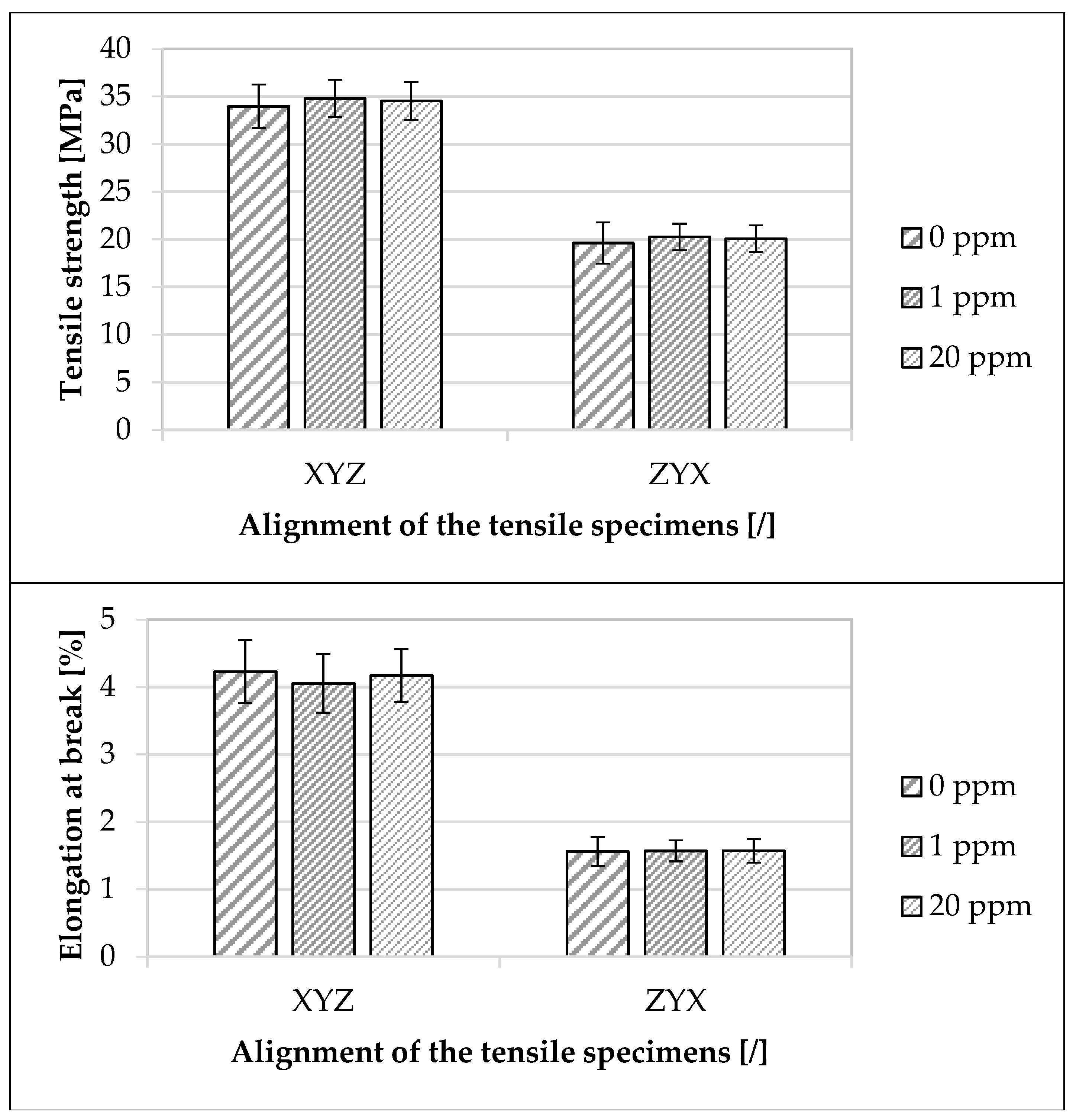
3.2. Influence on the Component Properties
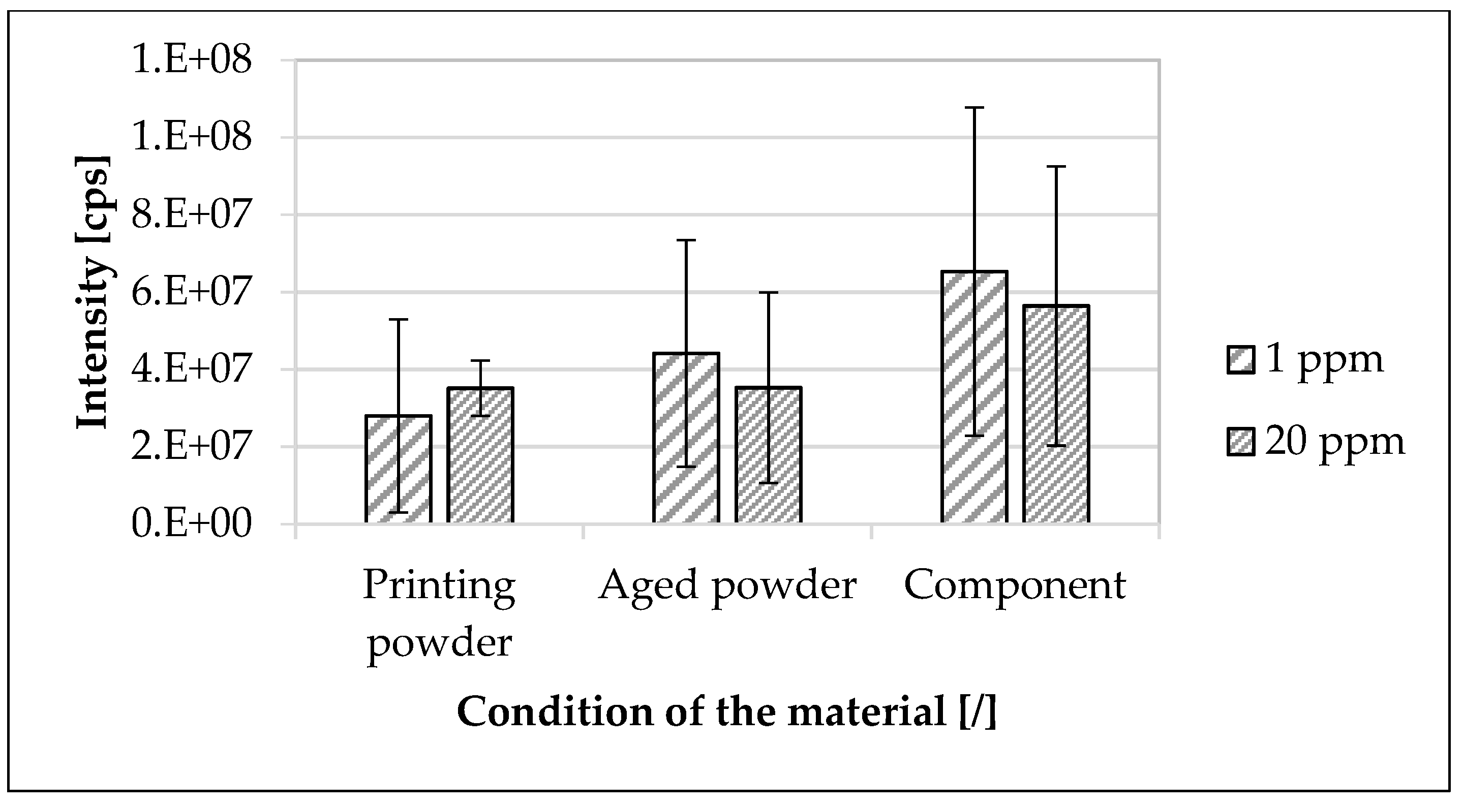
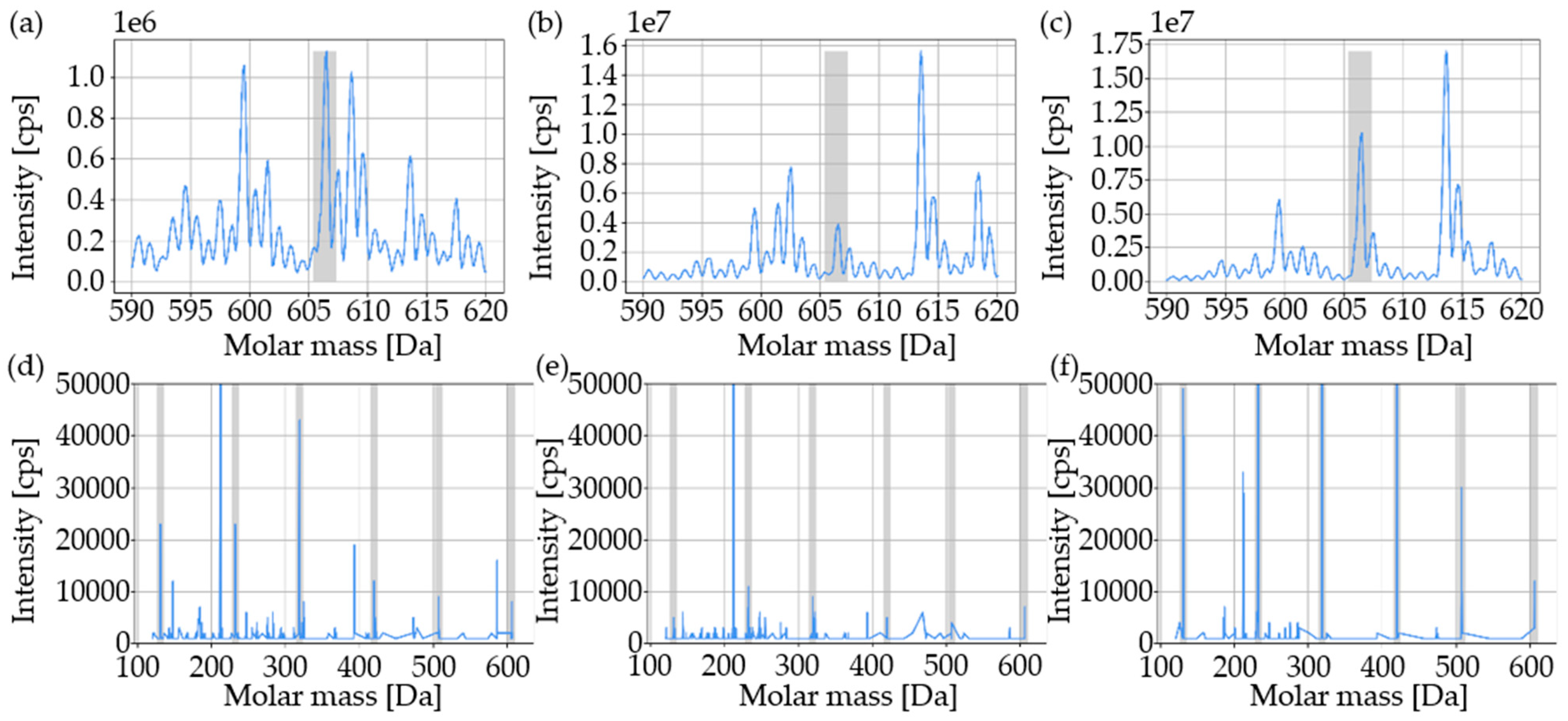
3.3. Traceability of the Marking Agent
4. Discussion
5. Conclusions
- Within the scope of the investigation and the applied concentrations of the used modified polymer in the used polyamide 12 sinter material, the marking agent had no discernible influence on the material and component properties;
- The used modified polymer could be reliably detected in the printing powders as well as in the used powder and component down to a concentration of 1 ppm;
- No clear correlation was found between the concentration of the modified polymer and the determined intensity of the modified polymer in the used sinter material;
- A higher traceability of the modified polymer was obtained in the component than in the powder;
- Mixing parameters allowed a sufficient dispersion of the sinter material and master batch;
- Modified polymers were suitable as marking agents in the SLS process and allowed encoding of the used sinter material at the molecular level.
Author Contributions
Funding
Institutional Review Board Statement
Informed Consent Statement
Data Availability Statement
Acknowledgments
Conflicts of Interest
References
- Breuninger, J.; Becker, R.; Wolf, A.; Rommel, S.; Verl, A. Generative Fertigung mit Kunststoffen: Konzeption und Konstruktion für Selektives Lasersintern; Springer: Berlin/Heidelberg, Germany, 2013; ISBN 978-3-642-24324-0. [Google Scholar]
- Gebhardt, A. Additive Fertigungsverfahren: Additive Manufacturing und 3D-Drucken für Prototyping-Tooling-Produktion; 5., neu bearbeitete und erweiterte Auflage; Hanser: München, Germany, 2016; ISBN 978-3-446-44401-0. [Google Scholar]
- Fastermann, P. 3D-Druck/Rapid Prototyping: Eine Zukunftstechnologie-kompakt erklärt; Springer: Berlin/Heidelberg, Germany, 2012; ISBN 978-3-642-29224-8. [Google Scholar]
- Gibson, I.; Rosen, D.; Stucker, B. Additive Manufacturing Technologies: 3D Printing, Rapid Prototyping and Direct Digital Manufacturing, 2nd ed.; Springer: New York, NY, USA; Heidelberg, Germany; Dodrecht, The Netherlands; London, UK, 2015; ISBN 978-1-4939-2112-6. [Google Scholar]
- Schmid, M. Selektives Lasersintern (SLS) mit Kunststoffen: Technologie, Prozesse und Werkstoffe; Hanser: München, Germany, 2015; ISBN 978-3-446-44562-8. [Google Scholar]
- Seppala, J.E.; Kotula, A.P.; Snyder, C.R. Polymer-Based Additive Manufacturing: Recent Developments; American Chemical Society: Washington, DC, USA, 2019; ISBN 9780841234260. [Google Scholar]
- Celik, E. Additive Manufacturing; De Gruyter: Berlin, Germany, 2020; ISBN 9781501518782. [Google Scholar]
- Schmid, M.; Amado, A.; Wegener, K. Polymer powders for selective laser sintering (SLS). In Proceedings of the 30th International Conference of the Polymer Processing Society–Conference Papers, Cleveland, OH, USA, 6–12 June 2014; AIP Publishing LLC: Long Island, NY, USA, 2015; p. 160009. [Google Scholar]
- Schmid, M.; Wegener, K. Additive Manufacturing: Polymers Applicable for Laser Sintering (LS). Procedia Eng. 2016, 149, 457–464. [Google Scholar] [CrossRef] [Green Version]
- Schulze, D. Pulver und Schüttgüter; Springer: Berlin/Heidelberg, Germany, 2019; ISBN 978-3-662-58775-1. [Google Scholar]
- Hirschberg, C.; Sun, C.C.; Risbo, J.; Rantanen, J. Effects of Water on Powder Flowability of Diverse Powders Assessed by Complimentary Techniques. J. Pharm. Sci. 2019, 108, 2613–2620. [Google Scholar] [CrossRef] [PubMed]
- Faqih, A.M.N.; Mehrotra, A.; Hammond, S.V.; Muzzio, F.J. Effect of moisture and magnesium stearate concentration on flow properties of cohesive granular materials. Int. J. Pharm. 2007, 336, 338–345. [Google Scholar] [CrossRef] [PubMed]
- Choren, J.; Gervasi, V.; Herman, T.; Kamara, S.; Mitchell, J. SLS powder life study. In Proceedings of the 2001 Solid Freeform Fabrication Symposium, Austin, TX, USA, 6–8 August 2001; pp. 39–45. [Google Scholar]
- Dahlmann, R.; Haberstroh, E.; Menges, G. Menges Werkstoffkunde Kunststoffe, Vollständig neu bearbeitete Auflage, 7th ed.; Hanser: Munich, Germany, 2022; ISBN 978-3-446-45801-7. [Google Scholar]
- Dotchev, K.; Yusoff, W. Recycling of polyamide 12 based powders in the laser sintering process. Rapid Prototyp. J. 2009, 15, 192–203. [Google Scholar] [CrossRef]
- Drummer, D.; Harder, R.G.; Witt, G.; Wegner, A.; Wudy, K.; Drexler, M. Long-term Properties of Laser Sintered Parts of Polyamide 12-Influence of Storage Time and Temperature on the Aging Behavior. Int. J. Recent Contrib. Eng. Sci. IT 2015, 3, 20. [Google Scholar] [CrossRef]
- Kühnlein, F.; Drummer, D.; Rietzel, D.; Seefried, A. Degradation behavior and material properties of PA 12 plastic powders processed by powder based additive manufacturing technologies. DAAAM International Vienna: Vienna, Austria. In Annals of DAAAM for 2010 & Proceedings of the 21st International DAAAM Symposium; DAAAM International: Vienna, Austria, 2010; Volume 21, pp. 1–2. [Google Scholar]
- Dadbakhsh, S.; Verbelen, L.; Verkinderen, O.; Strobbe, D.; van Puyvelde, P.; Kruth, J.-P. Effect of PA12 powder reuse on coalescence behaviour and microstructure of SLS parts. Eur. Polym. J. 2017, 92, 250–262. [Google Scholar] [CrossRef]
- Wudy, K.; Drummer, D.; Kühnlein, F.; Drexler, M. Influence of degradation behavior of polyamide 12 powders in laser sintering process on produced parts. In Proceedings of the 29th International Conference of the Polymer Processing Society-Conference Papers, Nuremberg, Germany, 15–19 July 2013; American Institute of Physics: College Park, MY, USA, 2014; pp. 691–695. [Google Scholar]
- Josupeit, S.; Lohn, J.; Hermann, E.; Gessler, M.; Tenbrink, S.; Schmid, H.-J. Material Properties of Laser Sintered Polyamide 12 as Function of Build Cycles Using Low Refresh Rates. In Proceedings of the 26th Annual International Solid Freeform Fabrication Symposium, Austin, TX, USA, 10–12 August 2015; pp. 540–549. [Google Scholar]
- Fiedler, L.; Androsch, R.; Mileva, D.; Radusch, H.J.; Wutzler, A.; Gerken, J. Experimentelle Simulation der physikalischen Alterung von Lasersinterpulvern. Z. Kunstst. 2010, 6, 19–32. [Google Scholar]
- Mielicki, C. Prozessnahes Qualitätsmanagement beim Lasersintern von Polyamid 12. Ph.D. Thesis, Universität Duisburg-Essen, Duisburg/Essen, Germany, 2014. [Google Scholar]
- Eggers, T.; von Lacroix, F.; van de Kraan, F.; Reichler, A.-K.; Hürkamp, A.; Dröder, K. Investigations for Material Tracing in Selective Laser Sintering: Part I: Methodical Selection of a Suitable Marking Agent. Materials 2023, 16, 1043. [Google Scholar] [CrossRef]
- Dittmer, G. Managen mit Methode: Instrumente für individuelle Lösungen; Gabler Verlag: Wiesbaden, Germany, 1995; ISBN 978-3-409-18790-9. [Google Scholar]
- Zimmermann, H.-J.; Gutsche, L. Multi-Criteria Analyse: Einführung in die Theorie der Entscheidungen bei Mehrfachzielsetzungen; Springer: Berlin/Heidelberg, Germany, 1991; ISBN 978-3-540-54483-8. [Google Scholar]
- Geldermann, J.; Lerche, N. Leitfaden zur Anwendung von Methoden der multikriteriellen Entscheidungsunterstützung. In Methode: Promethee; Lehrstuhl für Produktion und Logistik, Georg-August-Universität Göttingen: Göttingen, Germany, 2014. [Google Scholar]
- Brans, J.-P.; Vincke, P. Note—A Preference Ranking Organisation Method: (The PROMETHEE Method for Multiple Criteria Decision-Making). Manag. Sci. 1985, 31, 647–656. [Google Scholar] [CrossRef] [Green Version]
- Lutz, J.-F. Coding macromolecules: Inputting information in polymers using monomer-based alphabets. Macromolecules 2015, 48, 4759–4767. [Google Scholar] [CrossRef]
- Lutz, J.-F. Les Polymères, Messagers à l’Échelle Moléculaire. IT Ind. Technol. 2021, 1–11. [Google Scholar]
- Amado, A.; Schmid, M.; Levy, G.; Wegener, K. Advances in SLS powder characterization. In Proceedings of the 22nd Annual International Solid Freeform Fabrication Symposium-An Additive Manufacturing Conference, SFF, Austin, TX, USA, 8–10 August 2011. [Google Scholar]
- Goodridge, R.D.; Tuck, C.J.; Hague, R. Laser sintering of polyamides and other polymers. Prog. Mater. Sci. 2012, 57, 229–267. [Google Scholar] [CrossRef]
- LUVOSINT PA12 9270; BK-Polyamide 12 Unreinforced, Black: Preliminary Datasheet. Lehmann&Voss&Co. KG.: Hamburg, Germany, 2022.
- Dost, G.; Kummer, B.; Matloubi, M.; Moesslein, J.; Treick, A. Produkt- und Materialpässe nützen der Kreislaufwirtschaft nur, wenn sie Tatsächlich Robust mit Produkten und Materialien Verknüpft sind! Kurzfassung: Freiburg, Germany, 2022; Available online: https://polysecure.eu/fileadmin/main/Unternehmen/Media-Files/220425_Produkt_Materialpass_Kurzfassung_Dt.pdf (accessed on 20 August 2022).
- Dost, G.; Matloubi, M.; Treick, A.; Kummer, B. Booster für eine gelingende Kreislaufwirtschaft. Recycl. Mag. Sonderh. 2022, 4, 84–86. [Google Scholar]
- Youssef, I.; Carvin-Sergent, I.; Konishcheva, E.; Kebe, S.; Greff, V.; Karamessini, D.; Matloubi, M.; Ouahabi, A.A.; Moesslein, J.; Amalian, J.-A.; et al. Covalent Attachment and Detachment by Reactive DESI of Sequence-Coded Polymer Taggants. Macromol. Rapid Commun. 2022, 43, 2200412. [Google Scholar] [CrossRef] [PubMed]
- ISO 13322-2:2021-12; Particle Size Analysis-Image Analysis Methods-Part 2: Dynamic Image Analysis Methods. Internation Organization of Standardization: Vernier, OR, USA; Geneva, Switzerland, 2021.
- Eggers, T.; von Lacroix, F. Investigation of the Influence of the Mixing Process on the Powder and Component Properties during Cyclic Reuse of a Polyamide 12 Sinter Material in Selective Laser Sintering. Powders 2023, 2, 75–96. [Google Scholar] [CrossRef]
- Eggers, T.; Rackl, H.; Lacroix, F. von. Investigation of the Influence of the Mixing Process on the Powder Characteristics for Cyclic Reuse in Selective Laser Sintering. Powders 2023, 2, 32–46. [Google Scholar] [CrossRef]
- Wadell, H. Volume, Shape, and Roundness of Quartz Particles. J. Geol. 1935, 43, 250–280. [Google Scholar] [CrossRef]
- Blümel, C. Charakterisierung der Trockenen Beschichtung zur Herstellung von Maßgeschneiderten Kompositpartikeln; Universität Erlangen-Nürnberg: Erlangen, Germany, 2015; ISBN 978-3-8439-2120-6. [Google Scholar]
- Zhou, Q.; Qu, L.; Larson, I.; Stewart, P.J.; Morton, D.A. Effect of mechanical dry particle coating on the improvement of powder flowability for lactose monohydrate: A model cohesive pharmaceutical powder. Powder Technol. 2011, 207, 414–421. [Google Scholar] [CrossRef]
- Mullarney, M.P.; Beach, L.E.; Davé, R.N.; Langdon, B.A.; Polizzi, M.; Blackwood, D.O. Applying dry powder coatings to pharmaceutical powders using a comil for improving powder flow and bulk density. Powder Technol. 2011, 212, 397–402. [Google Scholar] [CrossRef]
- Abdullah, E.C.; Geldart, D. The use of bulk density measurements as flowability indicators. Powder Technol. 1999, 102, 151–165. [Google Scholar] [CrossRef]
- Spierings, A.B.; Voegtlin, M.; Bauer, T.; Wegener, K. Powder flowability characterisation methodology for powder-bed-based metal additive manufacturing. Prog. Addit. Manuf. 2016, 1, 9–20. [Google Scholar] [CrossRef] [Green Version]
- Carr, J.F.; Walker, D.M. An annular shear cell for granular materials. Powder Technol. 1968, 1, 369–373. [Google Scholar] [CrossRef]
- Carr, R.L., Jr. Evaluating flow properties of solids. Chem. Eng. 1965, 18, 163–168. [Google Scholar]
- DIN EN ISO 60:2000-01; Kunststoffe-Bestimmung der Scheinbaren Dichte von Formmassen, die Durch Einen Genormten Trichter Abfließen Können (Schüttdichte) (ISO_60:1977); Deutsche Fassung EN_ISO_60:1999. Beuth Verlag GmbH: Berlin, Germany, 2000.
- DIN EN ISO 787-11:1995-10; Allgemeine Prüfverfahren für Pigmente und Füllstoffe-Teil_11: Bestimmung des Stampfvolumens und der Stampfdichte (ISO_787-11:1981); Deutsche Fassung EN_ISO_787-11:1995. Beuth Verlag GmbH: Berlin, Germany, 1995.
- Frick, A.; Stern, C. Einführung in die Kunststoffprüfung: Prüfmethoden und Anwendungen; Hanser: München, Germany, 2017; ISBN 978-3-446-44351-8. [Google Scholar]
- DIN EN ISO 11357-1:2017-02; Kunststoffe-Dynamische Differenz-Thermoanalyse_(DSC)_-Teil_1: Allgemeine Grundlagen (ISO_11357-1:2016); Deutsche Fassung EN_ISO_11357-1:2016. Beuth Verlag GmbH: Berlin, Germany, 2017.
- DIN EN ISO 1133-1:2012-03; Kunststoffe-Bestimmung der Schmelze-Massefließrate (MFR) und der Schmelze-Volumenfließrate (MVR) von Thermoplasten-Teil_1: Allgemeines Prüfverfahren (ISO_1133-1:2011); Deutsche Fassung EN_ISO_1133-1:2011. Beuth Verlag GmbH: Berlin, Germany, 2012.
- Bhoite, K.; Kakandikar, G.M.; Nandedkar, V.M. Schatz Mechanism with 3D-Motion Mixer-A Review. Mater. Today Proc. 2015, 2, 1700–1706. [Google Scholar] [CrossRef]
- Jonat, S.; Hasenzahl, S.; Drechsler, M.; Albers, P.; Wagner, K.; Schmidt, P. Investigation of compacted hydrophilic and hydrophobic colloidal silicon dioxides as glidants for pharmaceutical excipients. Powder Technol. 2004, 141, 31–43. [Google Scholar] [CrossRef]
- Sommer, K. Mechanismen des Pulvermischens. Chem. Ing. Tech. 1977, 49, 305–311. [Google Scholar] [CrossRef]
- Weinekötter, R.; Gericke, H. Mischen von Feststoffen: Prinzipien, Verfahren, Mischer; Springer: Berlin/Heidelberg, Germany, 1995; ISBN 978-3-540-58567-1. [Google Scholar]
- Stieß, M. Mechanische Verfahrenstechnik-Partikeltechnologie 1; 3., vollst. neu bearb. Aufl.; Springer: Berlin/Heidelberg, Germany, 2009; ISBN 978-3-540-32551-2. [Google Scholar]
- Weber, S. Untersuchungen zum Einfluss der Mischintensität auf die Potenz Nanostrukturierter Fließregulierungsmittel. Ph.D. Thesis, Julius-Maximilians-Universität Würzburg, Würzburg, Germany, 2009. [Google Scholar]
- Mwania, F.M.; Maringa, M.; van der Walt, K. Mixing and Reuse of Polymer Laser Sintering Powders to Ensure Homogeneity—A Review. Int. J. Eng. Res. Technol. 2020, 13, 3335. [Google Scholar] [CrossRef]
- DIN EN ISO 527-2:2012-06; Kunststoffe-Bestimmung der Zugeigenschaften-Teil_2: Prüfbedingungen für Form- und Extrusionsmassen (ISO_527-2:2012); Deutsche Fassung EN_ISO_527-2:2012. Beuth Verlag GmbH: Berlin, Germany, 2012.
- DIN EN ISO 16396-2:2017-07; Kunststoffe-Polyamid_(PA)-Formmassen für das Spritzgießen und die Extrusion-Teil_2: Herstellung von Probekörpern und Bestimmung von Eigenschaften (ISO_16396-2:2017); Deutsche Fassung EN_ISO_16396-2:2017. Beuth Verlag GmbH: Berlin, Germany, 2017.
- DIN EN ISO 527-1:2019-12; Kunststoffe-Bestimmung der Zugeigenschaften-Teil_1: Allgemeine Grundsätze (ISO_527-1:2019); Deutsche Fassung EN_ISO_527-1:2019. Beuth Verlag GmbH: Berlin, Germany, 2019.
- DIN EN ISO 4287:2010-07; Geometrische Produktspezifikation (GPS)-Oberflächenbeschaffenheit: Tastschnittverfahren-Benennungen, Definitionen und Kenngrößen der Oberflächenbeschaffenheit (ISO_4287:1997_+ Cor_1:1998_+ Cor_2:2005_+ Amd_1:2009); Deutsche Fassung EN_ISO_4287:1998_+AC:2008_+A1:2009. Beuth Verlag GmbH: Berlin, Germany, 2010.
- DIN EN ISO 25178-1:2016-12; Geometrische Produktspezifikation_(GPS)-Oberflächenbeschaffenheit: Flächenhaft_- Teil_1: Angabe von Oberflächenbeschaffenheit (ISO_25178-1:2016); Deutsche Fassung EN_ISO_25178-1:2016. Beuth Verlag GmbH: Berlin, Germany, 2016.
- Thomas, D. The Development of Design Rules for Selective Laser Melting. Ph.D. Thesis, University of Wales, Cardiff, Wales, 2009. [Google Scholar]
- Schwanekamp, T.; Bräuer, M.; Reuber, M. Geometrical and topological potentialities and restrictions in selective laser sintering of customized carbide precision tools. In Proceedings of the Lasers in Manufacturing Conference, Munich, Germany; WLT: London, UK, 2017; pp. 26–29. [Google Scholar]
- Al Ouahabi, A.; Amalian, J.-A.; Charles, L.; Lutz, J.-F. Mass spectrometry sequencing of long digital polymers facilitated by programmed inter-byte fragmentation. Nat. Commun. 2017, 8, 967. [Google Scholar] [CrossRef] [Green Version]
- Gunay, U.S.; Petit, B.E.; Karamessini, D.; Al Ouahabi, A.; Amalian, J.-A.; Chendo, C.; Bouquey, M.; Gigmes, D.; Charles, L.; Lutz, J.-F. Chemoselective synthesis of uniform sequence-coded polyurethanes and their use as molecular tags. Chem 2016, 1, 114–126. [Google Scholar] [CrossRef] [Green Version]
- Lutz, J.-F.; Ouchi, M.; Liu, D.R.; Sawamoto, M. Sequence-controlled polymers. Science 2013, 341, 1238149. [Google Scholar] [CrossRef]
- Alscher, G. Das Verhalten teilkristalliner Thermoplaste beim Lasersintern. Ph.D. Thesis, Shaker, Aachen, Germany, 2000. [Google Scholar]
- Berretta, S.; Ghita, O.; Evans, K.E. Morphology of polymeric powders in Laser Sintering (LS): From Polyamide to new PEEK powders. Eur. Polym. J. 2014, 59, 218–229. [Google Scholar] [CrossRef]
- Drummer, D.; Wudy, K.; Drexler, M. Influence of energy input on degradation behavior of plastic components manufactured by selective laser melting. Phys. Procedia 2014, 56, 176–183. [Google Scholar] [CrossRef] [Green Version]
- Johnsen, U.; Spilgies, G.; Zachmann, H.G. Abhängigkeit der heterogenen Keimbildung in Polypropylen von der Kristallisationstemperatur und von der Art der Beimengung der Fremdsubstanz. Kolloid-Z.U.Z.Polym. 1970, 240, 762–765. [Google Scholar] [CrossRef]
- Bonnet, M. Kunststoffe in der Ingenieuranwendung: Verstehen und zuverlässig Auswählen; 1. Aufl.; Vieweg+Teubner Verlag/GWV Fachverlage GmbH Wiesbaden: Wiesbaden, Germany, 2009; ISBN 978-3-8348-0349-8. [Google Scholar]
- Buttitta, A. “Tracer-Based-Sorting”-Die Zukunft der Kunststoffverwertung. EU-Recycl.-Das Fachmag. Für Den Eur. Recycl. 2021, 38, 16–18. [Google Scholar]
- Gebhardt, A.; Kessler, J.; Thurn, L. 3D-Drucken: Grundlagen und Anwendungen des Additive Manufacturing (AM); 2., neu bearbeitete und erweiterte Auflage; Hanser: München, Germany, 2016; ISBN 978-3-446-44672-4. [Google Scholar]
- Dahmen, T.; Klingaa, C.G.; Baier-Stegmaier, S.; Lapina, A.; Pedersen, D.B.; Hattel, J.H. Characterization of channels made by laser powder bed fusion and binder jetting using X-ray CT and image analysis. Addit. Manuf. 2020, 36, 101445. [Google Scholar] [CrossRef]
- Gardan, J. Method for characterization and enhancement of 3D printing by binder jetting applied to the textures quality. Assem. Autom. 2017, 37, 162–169. [Google Scholar] [CrossRef]
- Wegner, A. Theorie über die Fortführung von Aufschmelzvorgängen als Grundvoraussetzung für Eine robuste Prozessführung beim Laser-Sintern von Thermoplasten. Ph.D. Thesis, Universität Duisburg-Essen, Duisburg, Essen, 2015. [Google Scholar]
- Wegner, A.; Mielicki, C.; Grimm, T.; Gronhoff, B.; Witt, G.; Wortberg, J. Determination of Robust Material Qualities and Processing Conditions for Laser Sintering of Polyamide 12. Polym. Eng. Sci. 2014, 54, 1540–1554. [Google Scholar] [CrossRef]
- Bastian, M.; Hochrein, T. Einfärben von Kunststoffen: Produktanforderungen-Verfahrenstechnik-Prüfmethodik; 2., aktualisierte und erweiterte Auflage; Hanser: München, Germany, 2018; ISBN 978-3-446-45398-2. [Google Scholar]
- Hornbogen, E.; Eggeler, G.; Werner, E. Werkstoffe: Aufbau und Eigenschaften von Keramik-, Metall-, Polymer- und Verbundwerkstoffen; 11.; Aktualisierte Auflage; Springer Vieweg: Berlin, Germany, 2017; ISBN 978-3-642-53866-7. [Google Scholar]
- Ehrenstein, G.W. Polymer-Werkstoffe: Struktur-Eigenschaften-Anwendung; 2., völlig überarb. Aufl.; Hanser: München, Germany, 1999; ISBN 9783446211612. [Google Scholar]
- Amalian, J.-A.; Mondal, T.; Konishcheva, E.; Cavallo, G.; Petit, B.E.; Lutz, J.-F.; Charles, L. Desorption electrospray ionization (DESI) of digital polymers: Direct tandem mass spectrometry decoding and imaging from materials surfaces. Adv. Mater. Technol. 2021, 6, 2001088. [Google Scholar] [CrossRef]
- Takats, Z.; Wiseman, J.M.; Gologan, B.; Cooks, R.G. Mass spectrometry sampling under ambient conditions with desorption electrospray ionization. Science 2004, 306, 471–473. [Google Scholar] [CrossRef] [Green Version]
- Cooks, R.G.; Ouyang, Z.; Takats, Z.; Wiseman, J.M. Ambient mass spectrometry. Science 2006, 311, 1566–1570. [Google Scholar] [CrossRef]


| Type | Dimension | Number | Usage |
|---|---|---|---|
| Tensile bar XYZ | 1BA 1 | 10 | Tensile test |
| Tensile bar ZYX | 1BA 1 | 10 | Tensile test |
| Cube 2 | 15 × 15 × 15 mm | 9 | Sinter density, surface roughness |
| Cube 3 | 15 × 15 × 15 mm | 8 | Traceability |
| Option | Selected Setting |
|---|---|
| Measuring method | Composition |
| Measuring mode | Manual |
| Resolution | Fine |
| Brightness | Auto (150) |
| Measuring view | Single view |
| Rotation method | Set angle |
| Degree | 360° |
| Rotation segment | 60° |
| Option | Selected Setting |
|---|---|
| Lens | 800XS |
| Operating distance | 1 mm |
| Brightness | 100% |
| Exposure | 40 ms |
| Reinforcement | 1.5 dB |
| Measuring field | 2.1401 mm × 2.1401 mm |
| Sample | Analyzed Quantity | Extraction Method | Duration in Ultrasonic Bath |
|---|---|---|---|
| Powder | 0.5 g | Mixed with 10 mL ethanol Placed in ultrasonic bath at 40 °C Filtration with 22 μm filter Placed in a rotary vacuum evaporator Dilution with 2 mL methanol and 3 mmol ammonium acetate | 30 min |
| Component | 2 cubes 1 (3.3 g/cube) | 60 min |
| Properties | Sinter Material | Master Batch |
|---|---|---|
| D10 (μm) | 28.2 | 28.7 |
| D50 (μm) | 66.3 | 65.2 |
| D90 (μm) | 100.0 | 99.0 |
| Sphericity (-) | 0.838 | 0.841 |
| Aspect ratio (-) | 0.710 | 0.712 |
| Bulk density (g/cm3) | 0.391 ± 0.003 | 0.390 ± 0.003 |
| Tap density (g/cm3) | 0.503 ± 0.003 | 0.502 ± 0.002 |
| Crystallization temperature (°C) | 157.73 | 157.51 |
| Melting temperature (°C) | 181.92 | 181.61 |
| MFR (g/10 min) | 14.67 ± 1.14 | 14.45 ± 0.83 |
Disclaimer/Publisher’s Note: The statements, opinions and data contained in all publications are solely those of the individual author(s) and contributor(s) and not of MDPI and/or the editor(s). MDPI and/or the editor(s) disclaim responsibility for any injury to people or property resulting from any ideas, methods, instructions or products referred to in the content. |
© 2023 by the authors. Licensee MDPI, Basel, Switzerland. This article is an open access article distributed under the terms and conditions of the Creative Commons Attribution (CC BY) license (https://creativecommons.org/licenses/by/4.0/).
Share and Cite
Eggers, T.; von Lacroix, F.; Goede, M.F.; Persch, C.; Berlin, W.; Dröder, K. Investigations for Material Tracing in Selective Laser Sintering: Part ΙΙ: Validation of Modified Polymers as Marking Agents. Materials 2023, 16, 2631. https://doi.org/10.3390/ma16072631
Eggers T, von Lacroix F, Goede MF, Persch C, Berlin W, Dröder K. Investigations for Material Tracing in Selective Laser Sintering: Part ΙΙ: Validation of Modified Polymers as Marking Agents. Materials. 2023; 16(7):2631. https://doi.org/10.3390/ma16072631
Chicago/Turabian StyleEggers, Tom, Frank von Lacroix, Martin Friedrich Goede, Christoph Persch, Werner Berlin, and Klaus Dröder. 2023. "Investigations for Material Tracing in Selective Laser Sintering: Part ΙΙ: Validation of Modified Polymers as Marking Agents" Materials 16, no. 7: 2631. https://doi.org/10.3390/ma16072631