
Effect of Crystallographic Orientations on Bendability in a Strongly Textured Mg-9Al Extrusion Plate and Texture Evolution during Three-Point Bending

Abstract
:1. Introduction
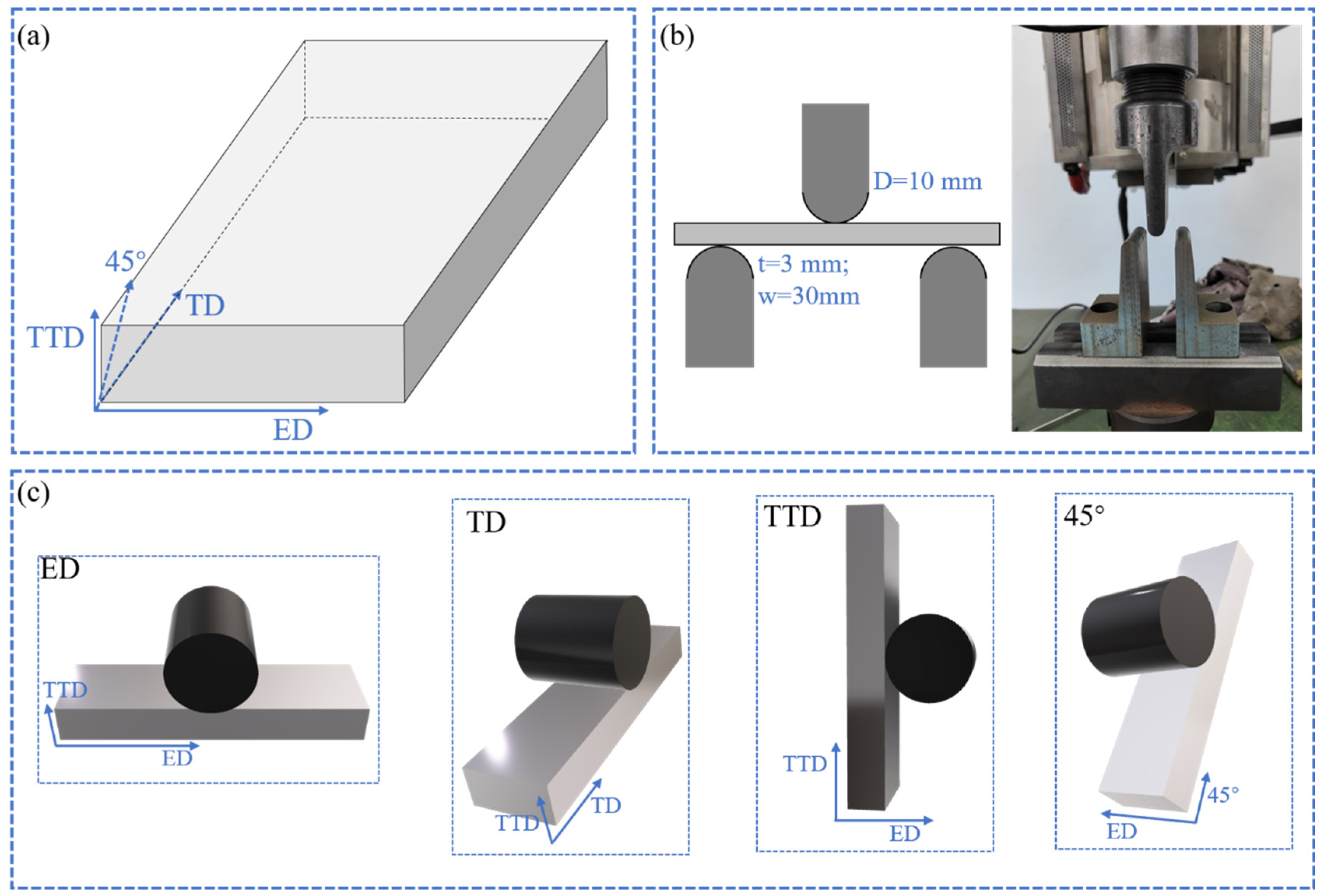
2. Experiments
3. Results
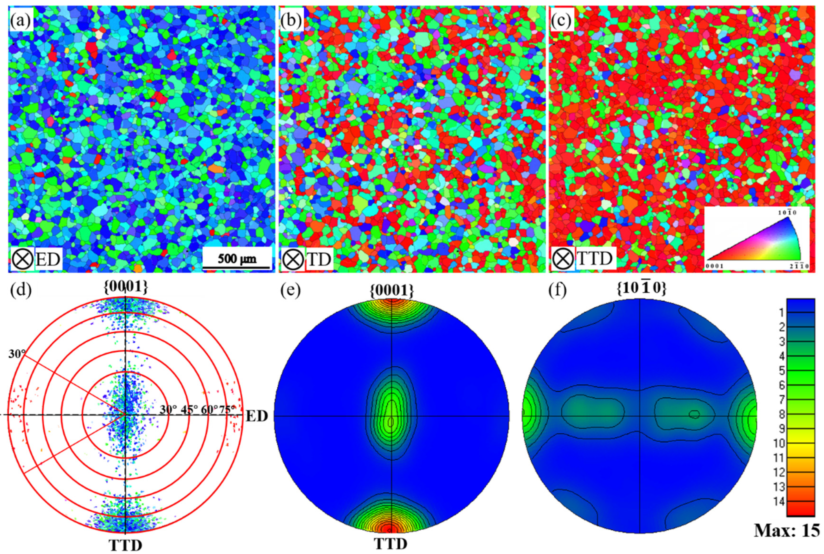
3.1. Initial Microstructure and Texture
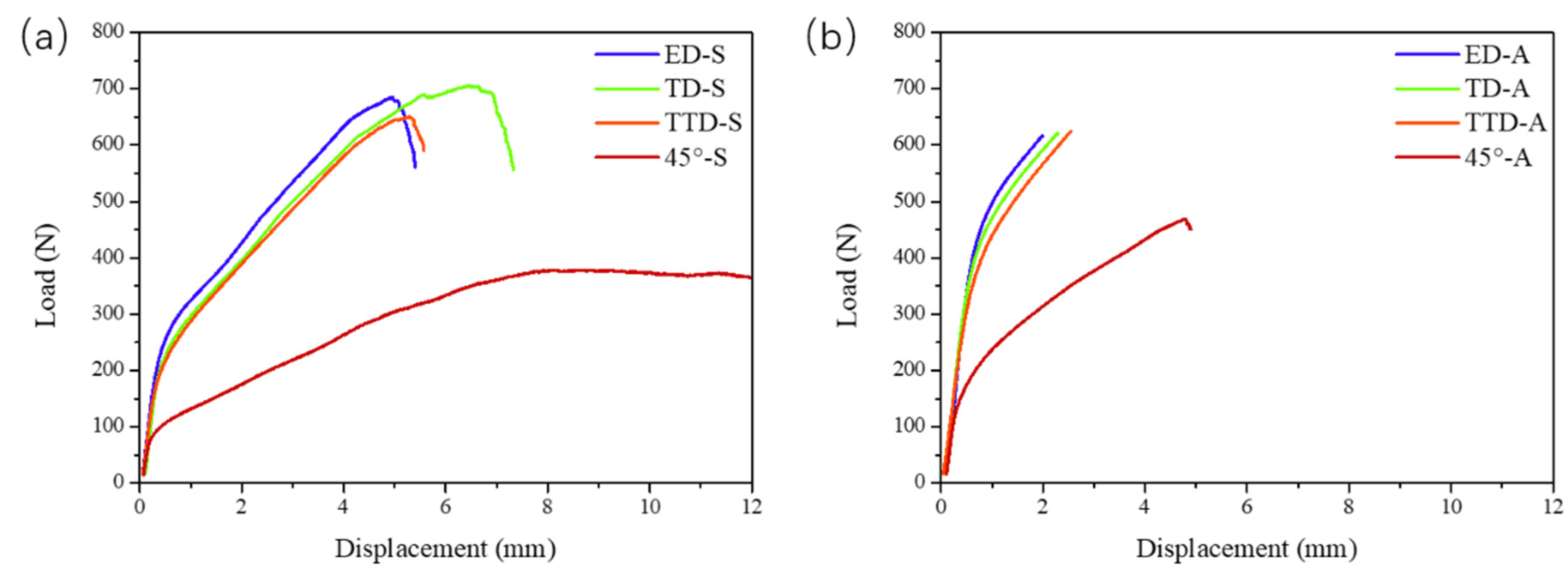
3.2. Bending Performance
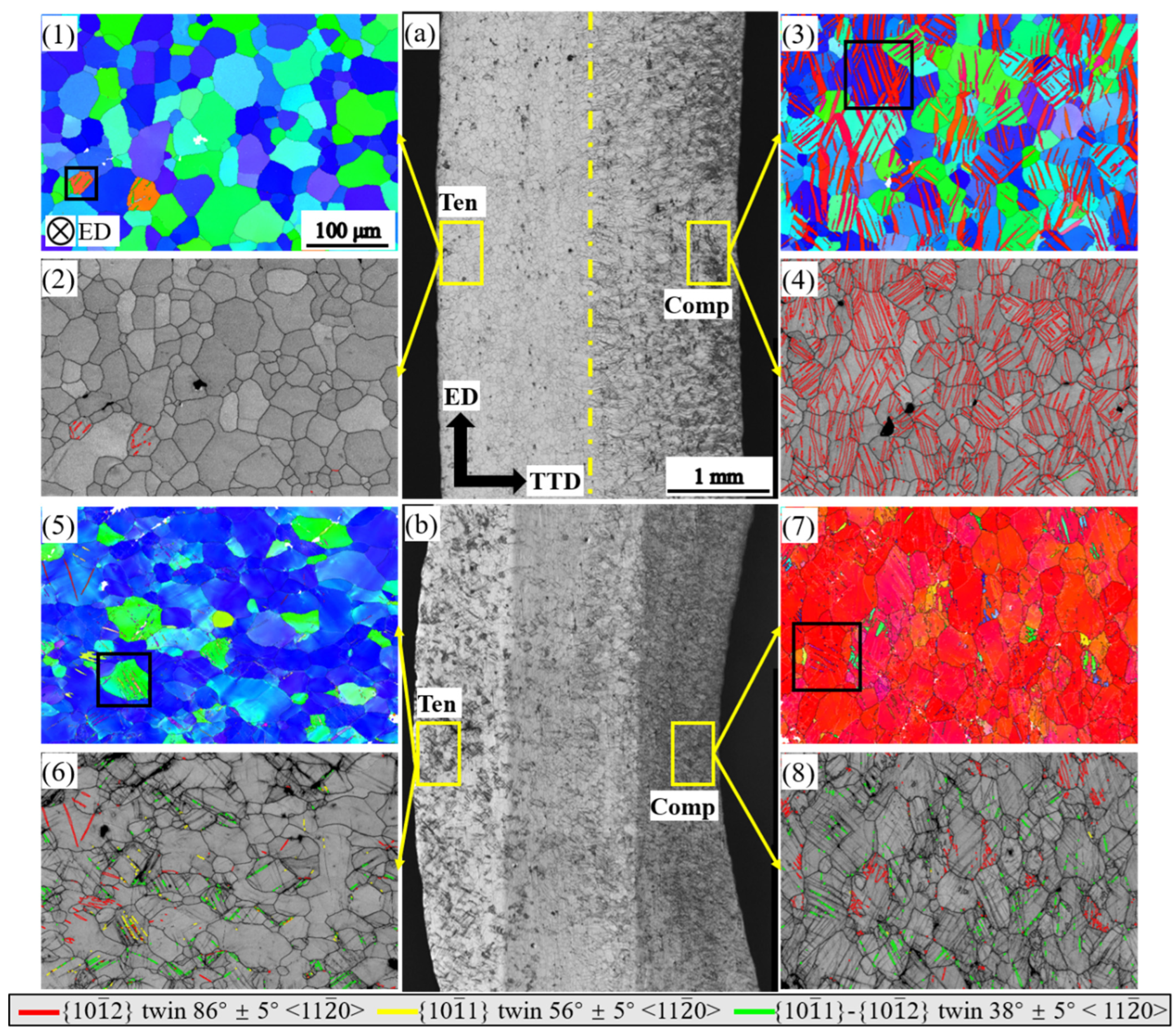
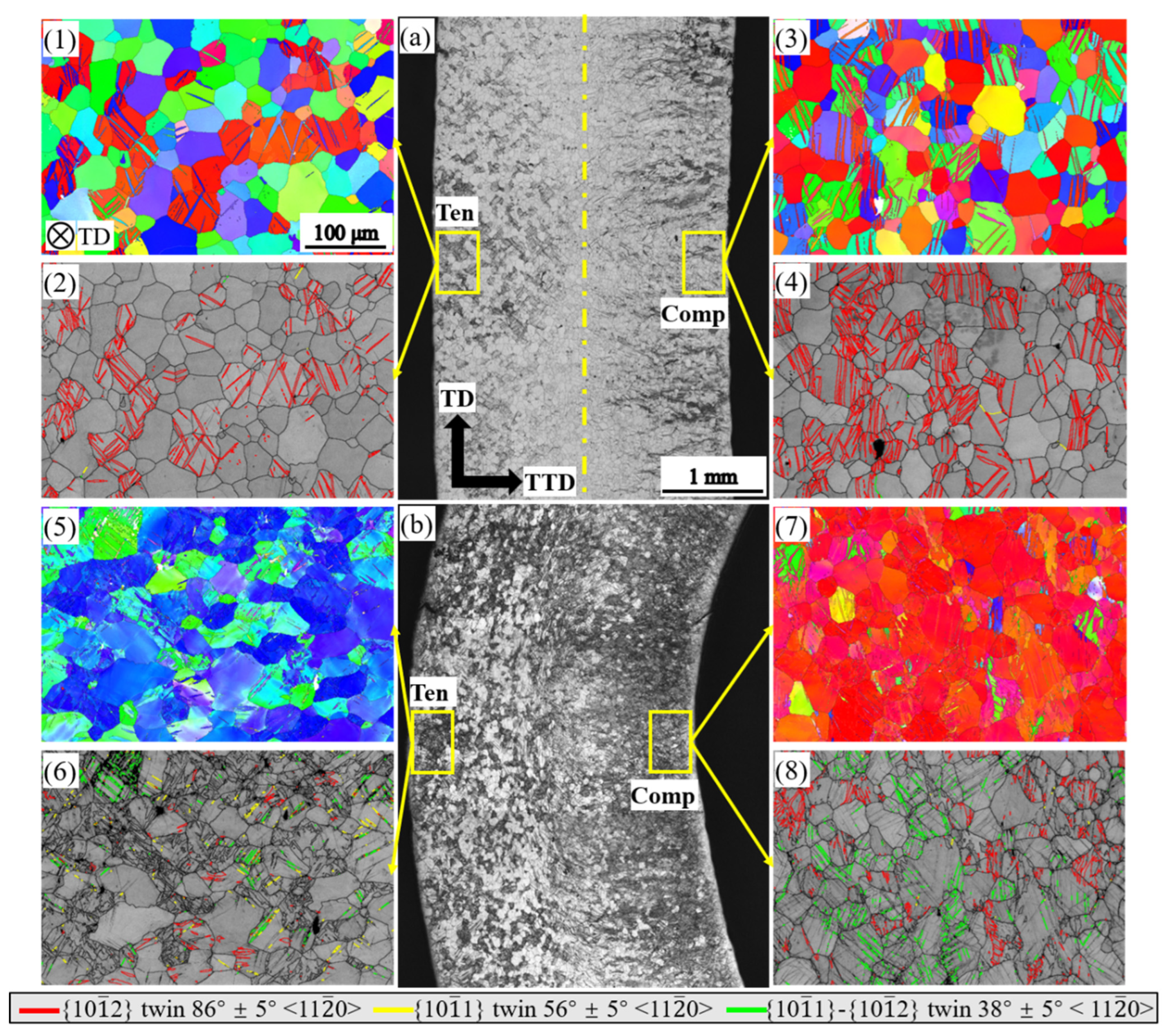
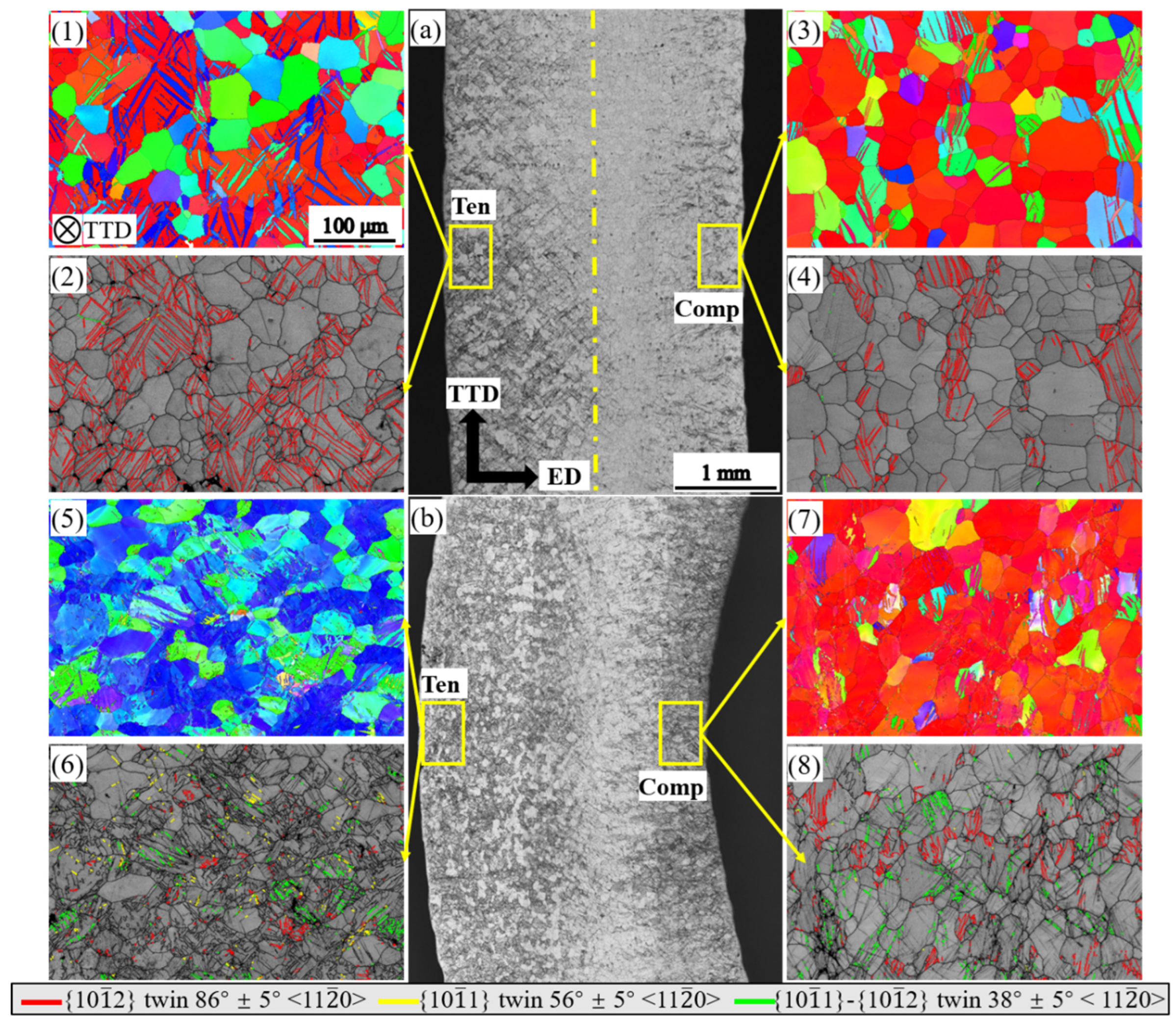
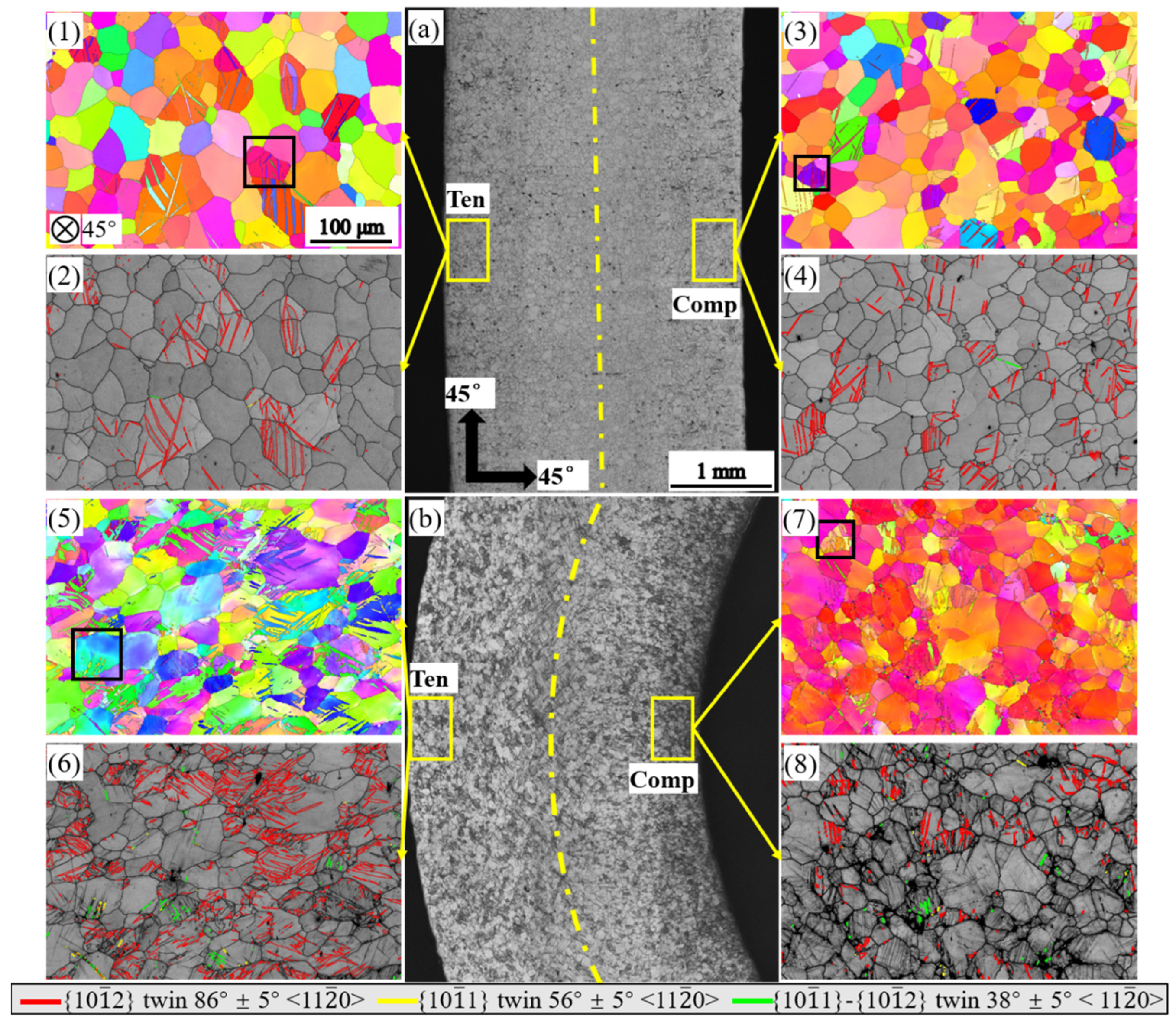
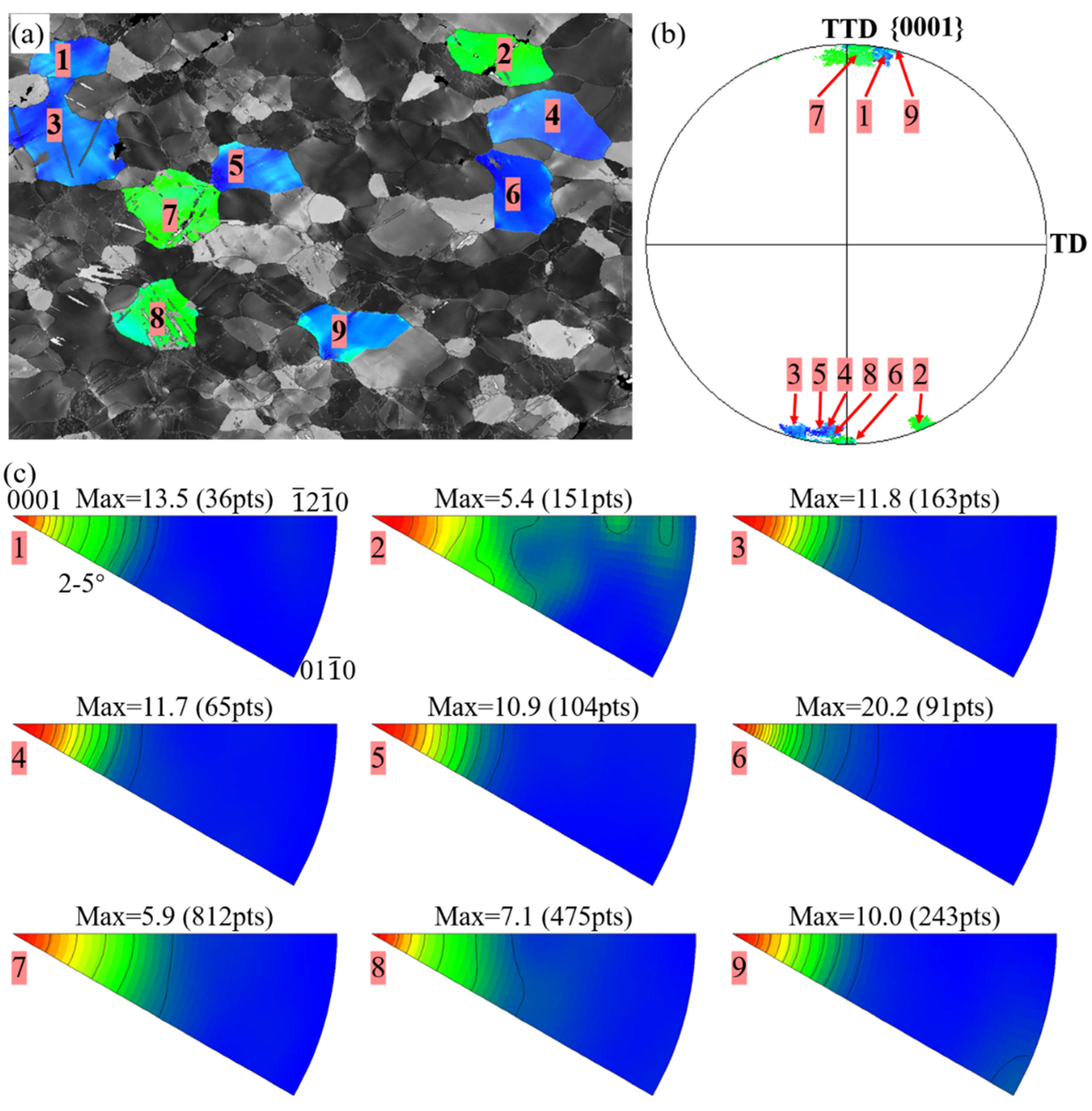
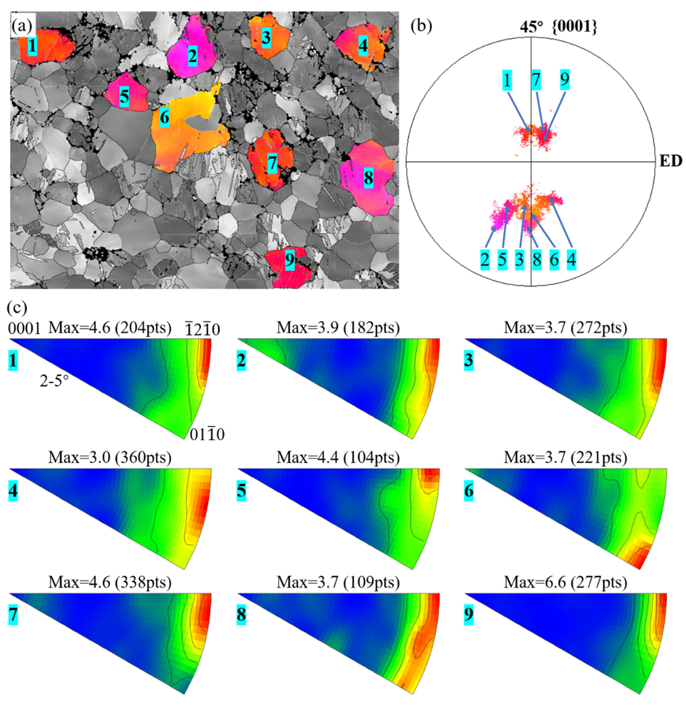
3.3. Microstructure and Texture during Bending
4. Discussion
4.1. Dependence of Bendability on Grain Orientation
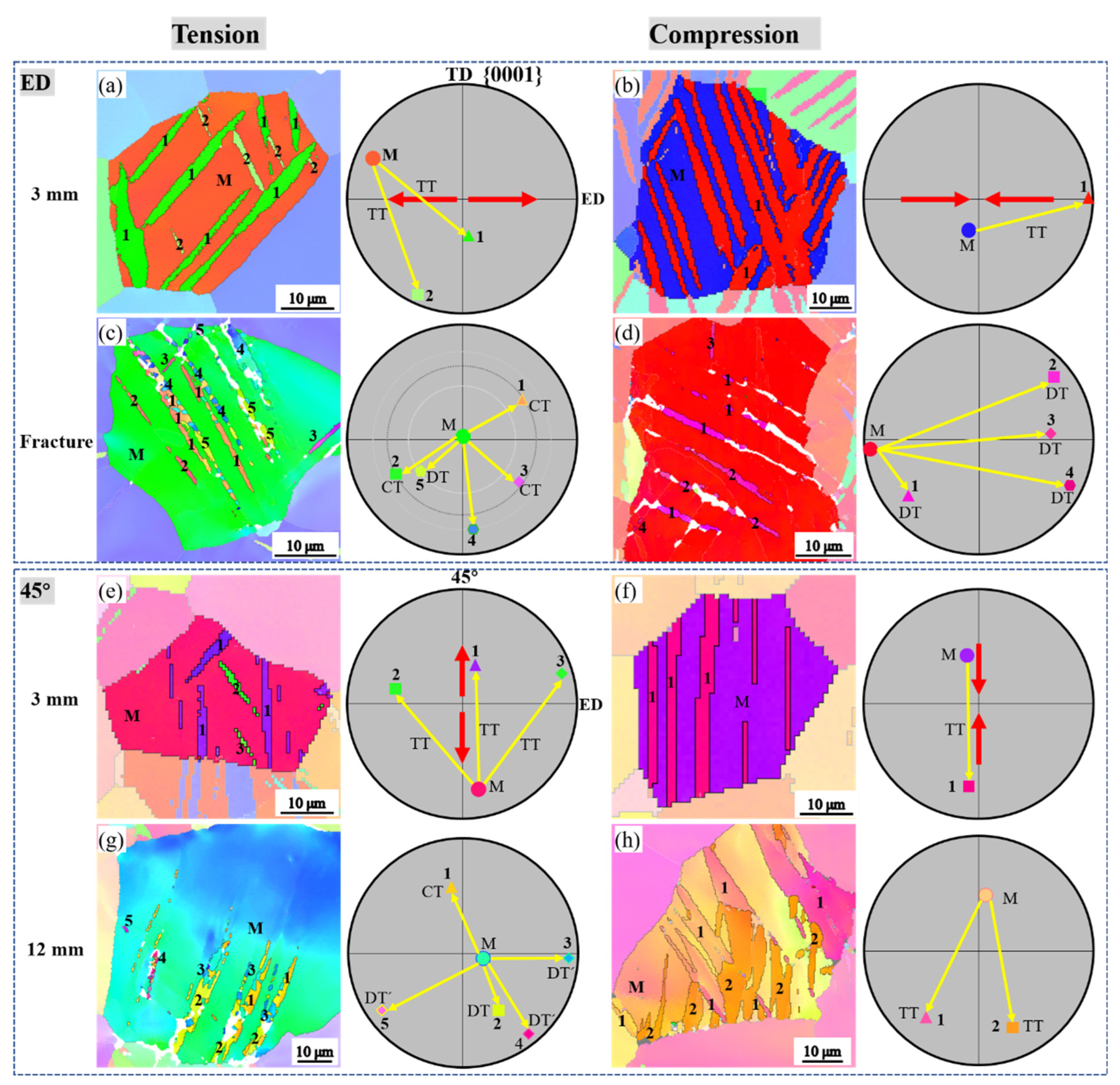
4.2. Deformation Mechanisms and Their Effect on Texture Evolution
4.2.1. Tensile Twinning
4.2.2. Contraction Twinning
4.2.3. Prismatic <a> Slip
4.2.4. Basal Slip
4.2.5. Effect of Deformation Mechanisms on Texture Evolution
4.3. The Critical Role of Texture on Bendability
5. Summary
- The strongly-textured Mg-9Al plate has a relatively low bendability when bent along ED, TD, and TTD; when bent along the 45°, the plate’s bendability is dramatically enhanced.
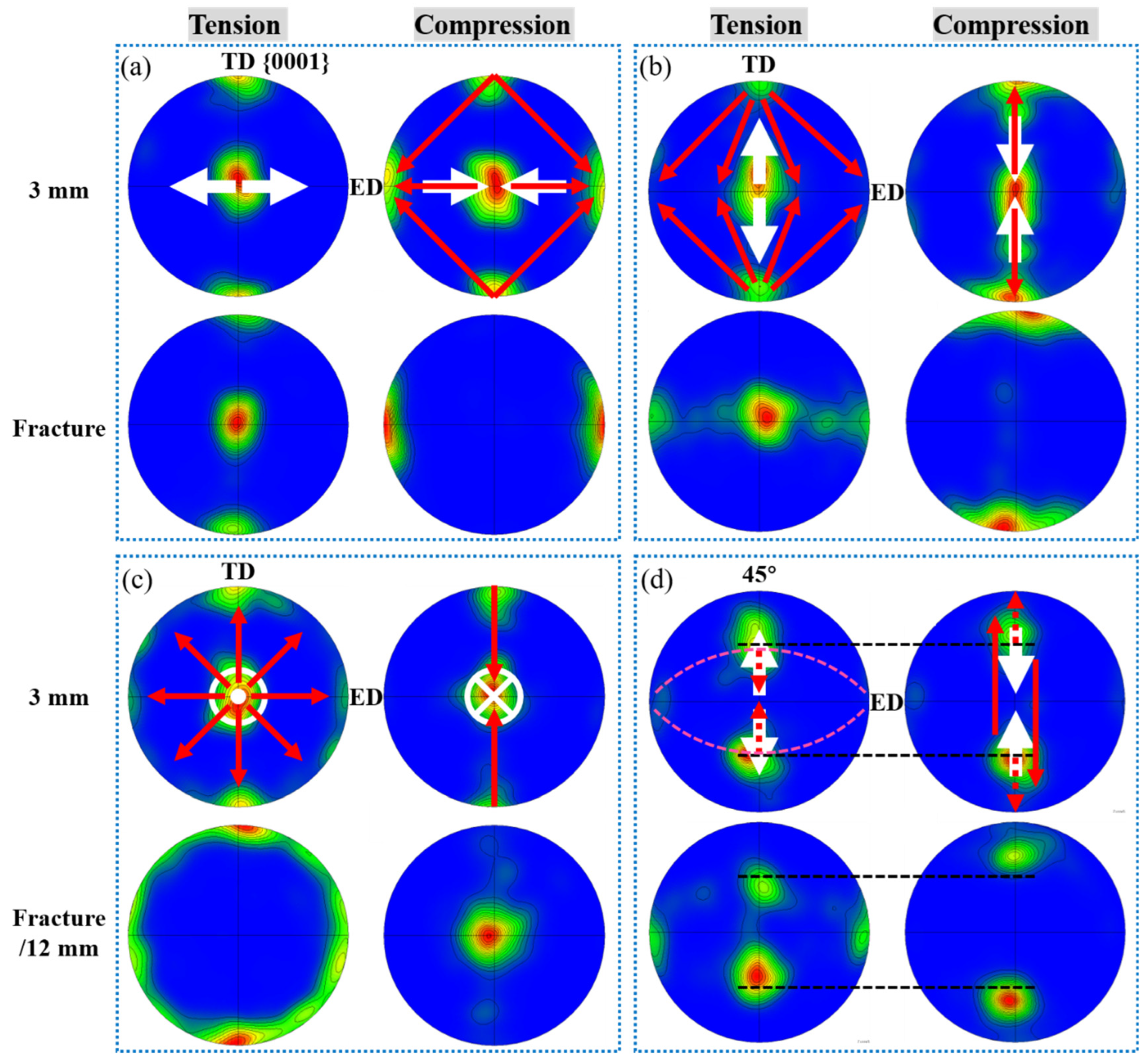
- Bending along the three orthogonal directions activates extensive tensive twinning and prismatic slip while bending along the 45° direction activates mainly basal slip.
- The texture evolves uniformly towards the formation of basal textures when bent along all four directions: at the tension side of the bars, the basal plane is reoriented parallel to the direction of tensile stress, while on the inner side, the basal plane is reoriented perpendicular to the direction of compressive stress.
- The transforming efficiency towards the basal textures is high by {102} twinning and low by basal slip. The 45° bar’s high bendability can be explained by its efficiency in forming the basal textures during bending, and subsequently, the occurrence of contraction twins and fracture is postponed.
- This study shows that bendability can be improved by adjusting orientation, and the primary focus should be on those methods with which basal slip is enhanced.
Author Contributions
Funding
Institutional Review Board Statement
Informed Consent Statement
Data Availability Statement
Acknowledgments
Conflicts of Interest
References
- Mordike, B.L.; Ebert, T. Magnesium: Properties-applications-potential. Mater. Sci. Eng. A 2001, 302, 37–45. [Google Scholar] [CrossRef]
- Joost, W.J.; Krajewski, P.E. Towards magnesium alloys for high-volume automotive applications. Scr. Mater. 2017, 128, 107–112. [Google Scholar] [CrossRef]
- Bettles, C.J.; Gibson, M.A. Current wrought magnesium alloys: Strengths and weaknesses. Jom 2005, 57, 46–49. [Google Scholar] [CrossRef]
- Suh, B.-C.; Shim, M.-S.; Shin, K.; Kim, N.J. Current issues in magnesium sheet alloys: Where do we go from here? Scr. Mater. 2014, 84, 1–6. [Google Scholar] [CrossRef]
- Baird, J.; Li, B.; Parast, S.Y.; Horstemeyer, S.; Hector, L.; Wang, P.; Horstemeyer, M. Localized twin bands in sheet bending of a magnesium alloy. Scr. Mater. 2012, 67, 471–474. [Google Scholar] [CrossRef]
- Chino, Y.; Kimura, K.; Mabuchi, M. Deformation characteristics at room temperature under biaxial tensile stress in textured AZ31 Mg alloy sheets. Acta Mater. 2009, 57, 1476–1485. [Google Scholar] [CrossRef]
- Azghandi, S.H.M.; Weiss, M.; Barnett, M.R. The effect of grain size on the bend forming limits in AZ31 Mg alloy. Jom 2020, 72, 2586–2596. [Google Scholar] [CrossRef]
- He, C.; Yuan, M.; Jiang, B.; Liu, L.; Wang, Q.; Chai, Y.; Liu, W.; Huang, G.; Zhang, D.; Pan, F. Anomalous effect of grain size on the room-temperature bendability of Mg-Gd alloy sheet. Mater. Sci. Eng. A 2022, 832, 142397. [Google Scholar] [CrossRef]
- Aslam, I.; Li, B.; McClelland, Z.; Horstemeyer, S.; Ma, Q.; Wang, P.; Horstemeyer, M. Three-point bending behavior of a ZEK100 Mg alloy at room temperature. Mater. Sci. Eng. A 2014, 590, 168–173. [Google Scholar] [CrossRef]
- Habibnejad-Korayem, M.; Jain, M.K.; Mishra, R.K. Microstructure modification and bendability improvement of AZ31 magnesium sheet by bending–unbending and annealing process. Mater. Sci. Eng. A 2015, 648, 371–384. [Google Scholar] [CrossRef]
- He, W.; Zeng, Q.; Yu, H.; Xin, Y.; Luan, B.; Liu, Q. Improving the room temperature stretch formability of a Mg alloy thin sheet by pre-twinning. Mater. Sci. Eng. A 2016, 655, 1–8. [Google Scholar] [CrossRef]
- Lee, J.U.; Kim, S.-H.; Kim, Y.J.; Park, S.H. Improvement in bending formability of rolled magnesium alloy through precompression and subsequent annealing. J. Alloy. Compd. 2019, 787, 519–526. [Google Scholar] [CrossRef]
- He, C.; Jiang, B.; Wang, Q.; Chai, Y.; Zhao, J.; Yuan, M.; Huang, G.; Zhang, D.; Pan, F. Effect of precompression and subsequent annealing on the texture evolution and bendability of Mg-Gd binary alloy. Mater. Sci. Eng. A 2020, 799, 140290. [Google Scholar] [CrossRef]
- Wei, J.; Liu, C.; Wan, Y.; Shao, J.; Han, X.; Zhang, G. Strengthening against {101¯2} twinning by discontinuous and continuous precipitate in a strongly textured Mg-9Al alloy. Mater. Charact. 2020, 167, 110523. [Google Scholar] [CrossRef]
- Stanford, N.; Geng, J.; Chun, Y.; Davies, C.; Nie, J.; Barnett, M. Effect of plate-shaped particle distributions on the deformation behaviour of magnesium alloy AZ91 in tension and compression. Acta Mater. 2012, 60, 218–228. [Google Scholar] [CrossRef]
- Xu, S.; Kamado, S.; Matsumoto, N.; Honma, T.; Kojima, Y. Recrystallization mechanism of as-cast AZ91 magnesium alloy during hot compressive deformation. Mater. Sci. Eng. A 2009, 527, 52–60. [Google Scholar] [CrossRef]
- Serra, A.; Pond, R.; Bacon, D. Computer simulation of the structure and mobility of twinning disclocations in H.C.P. Metals. Acta Met. Mater. 1991, 39, 1469–1480. [Google Scholar] [CrossRef]
- Chun, Y.B.; Battaini, M.; Davies, C.H.J.; Hwang, S.K. Distribution Characteristics of In-Grain Misorientation Axes in Cold-Rolled Commercially Pure Titanium and Their Correlation with Active Slip Modes. Met. Mater. Trans. A 2010, 41, 3473–3487. [Google Scholar] [CrossRef]
- Chun, Y.B.; Davies, C.H.J. Investigation of prism <a> slip in warm-rolled AZ31 alloy. Metall. Mater. Trans. A—Phys. Metall. Mater. Sci. 2011, 42, 4113–4125. [Google Scholar]
- Yamasaki, M.; Hagihara, K.; Inoue, S.-I.; Hadorn, J.P.; Kawamura, Y. Crystallographic classification of kink bands in an extruded Mg-Zn-Y alloy using intragranular misorientation axis analysis. Acta Mater. 2013, 61, 2065–2076. [Google Scholar] [CrossRef]
- Hutchinson, W.B.; Barnett, M.R. Effective values of critical resolved shear stress for slip in polycrystalline magnesium and other hcp metals. Scr. Mater. 2010, 63, 737–740. [Google Scholar] [CrossRef]
- Shao, J.; Chen, Z.; Chen, T.; Liu, C. Deformation Mechanism of Mg-Gd-Y-Zn-Zr Alloy Containing Long-Period Stacking Ordered Phases During Hot Rolling. Met. Mater. Trans. A 2020, 51, 1911–1923. [Google Scholar] [CrossRef]
- Mayama, T.; Noda, M.; Chiba, R.; Kuroda, M. Crystal plasticity analysis of texture development in magnesium alloy during extrusion. Int. J. Plast. 2011, 27, 1916–1935. [Google Scholar] [CrossRef] [Green Version]
- Reid, C.N. Deformation Geometry for Materials Scientists: International Series on Materials Science and Technology; Elsevier: Amsterdam, The Netherlands, 2016. [Google Scholar]
- Barnett, M.R. Twinning and the ductility of magnesium alloys: Part II. “Contraction” twins. Mater. Sci. Eng. A 2007, 464, 8–16. [Google Scholar] [CrossRef]


| Direction | 3 mm Ten | 3 mm Comp | Fracture/12 mm Ten | Fracture/12 mm Comp |
|---|---|---|---|---|
| ED | 0.5% | 28% | 3% | 94% |
| TD | 5.7% | 14.7% | 36.5% | 55% |
| TTD | 19% | 8.4% | 60.5% | 25% |
| 45° | 5.8% | 3% | 20.7% | 12% |
Disclaimer/Publisher’s Note: The statements, opinions and data contained in all publications are solely those of the individual author(s) and contributor(s) and not of MDPI and/or the editor(s). MDPI and/or the editor(s) disclaim responsibility for any injury to people or property resulting from any ideas, methods, instructions or products referred to in the content. |
© 2023 by the authors. Licensee MDPI, Basel, Switzerland. This article is an open access article distributed under the terms and conditions of the Creative Commons Attribution (CC BY) license (https://creativecommons.org/licenses/by/4.0/).
Share and Cite
Wei, J.; Jiang, S.; Wan, Y.; Liu, C. Effect of Crystallographic Orientations on Bendability in a Strongly Textured Mg-9Al Extrusion Plate and Texture Evolution during Three-Point Bending. Materials 2023, 16, 2518. https://doi.org/10.3390/ma16062518
Wei J, Jiang S, Wan Y, Liu C. Effect of Crystallographic Orientations on Bendability in a Strongly Textured Mg-9Al Extrusion Plate and Texture Evolution during Three-Point Bending. Materials. 2023; 16(6):2518. https://doi.org/10.3390/ma16062518
Chicago/Turabian StyleWei, Jiansheng, Shunong Jiang, Yingchun Wan, and Chuming Liu. 2023. "Effect of Crystallographic Orientations on Bendability in a Strongly Textured Mg-9Al Extrusion Plate and Texture Evolution during Three-Point Bending" Materials 16, no. 6: 2518. https://doi.org/10.3390/ma16062518