
Characterization of Green Part of Steel from Metal Injection Molding: An Analysis Using Moldflow

 , and
, and 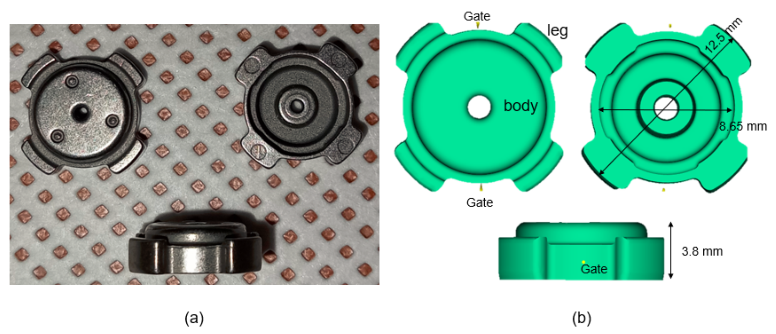
Abstract
:1. Introduction
2. Materials and Methods
2.1. Powder and Feedstock
2.2. Metal Injection Molding (MIM)
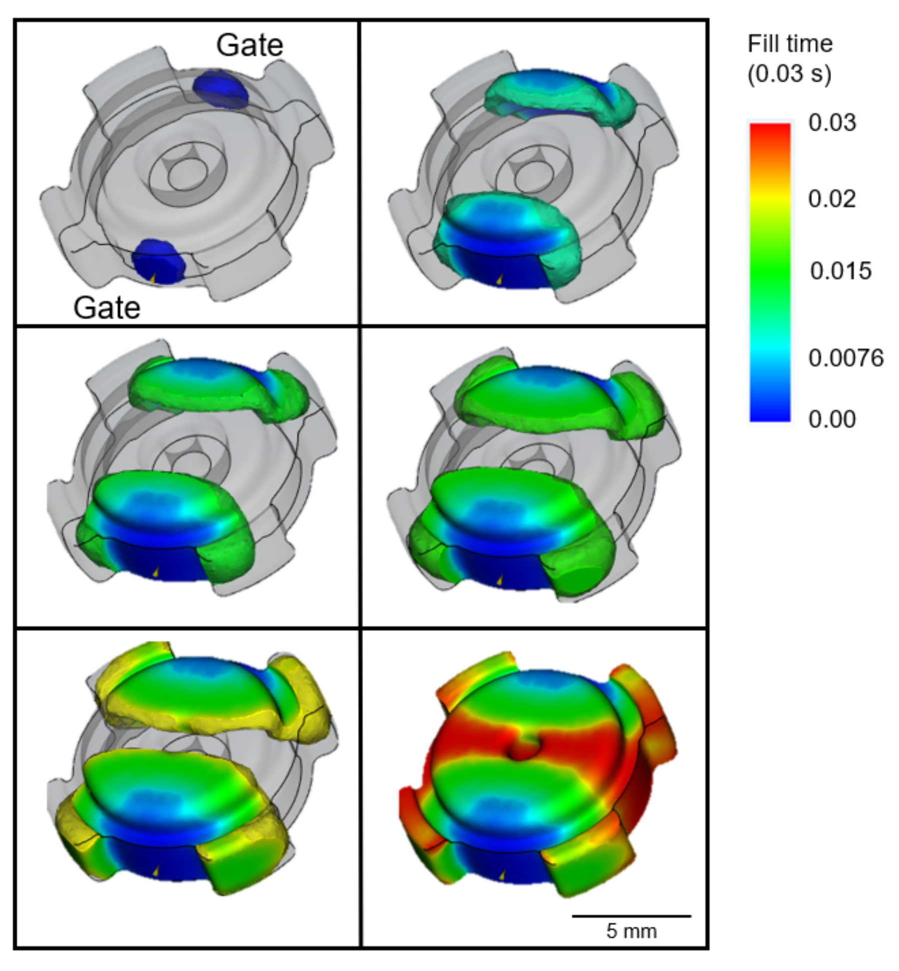
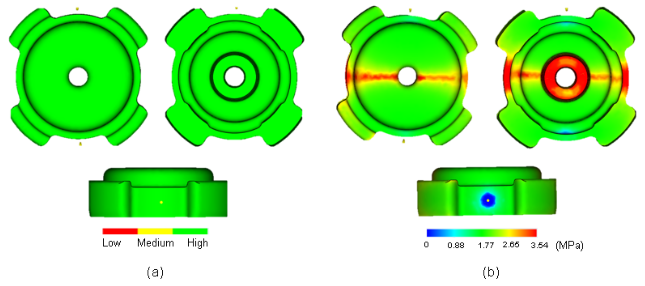
2.3. Moldflow Simulation
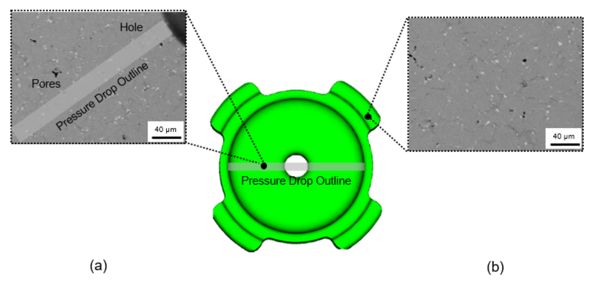
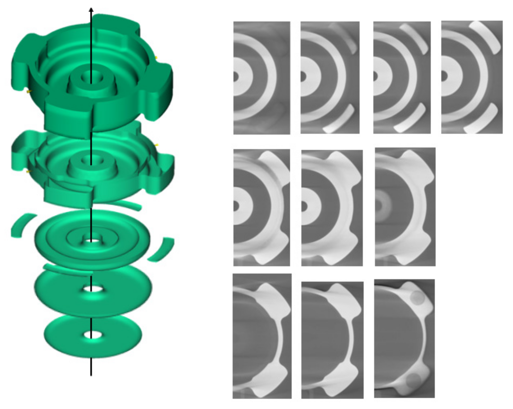
2.4. X-ray Computed Tomography (XCT)
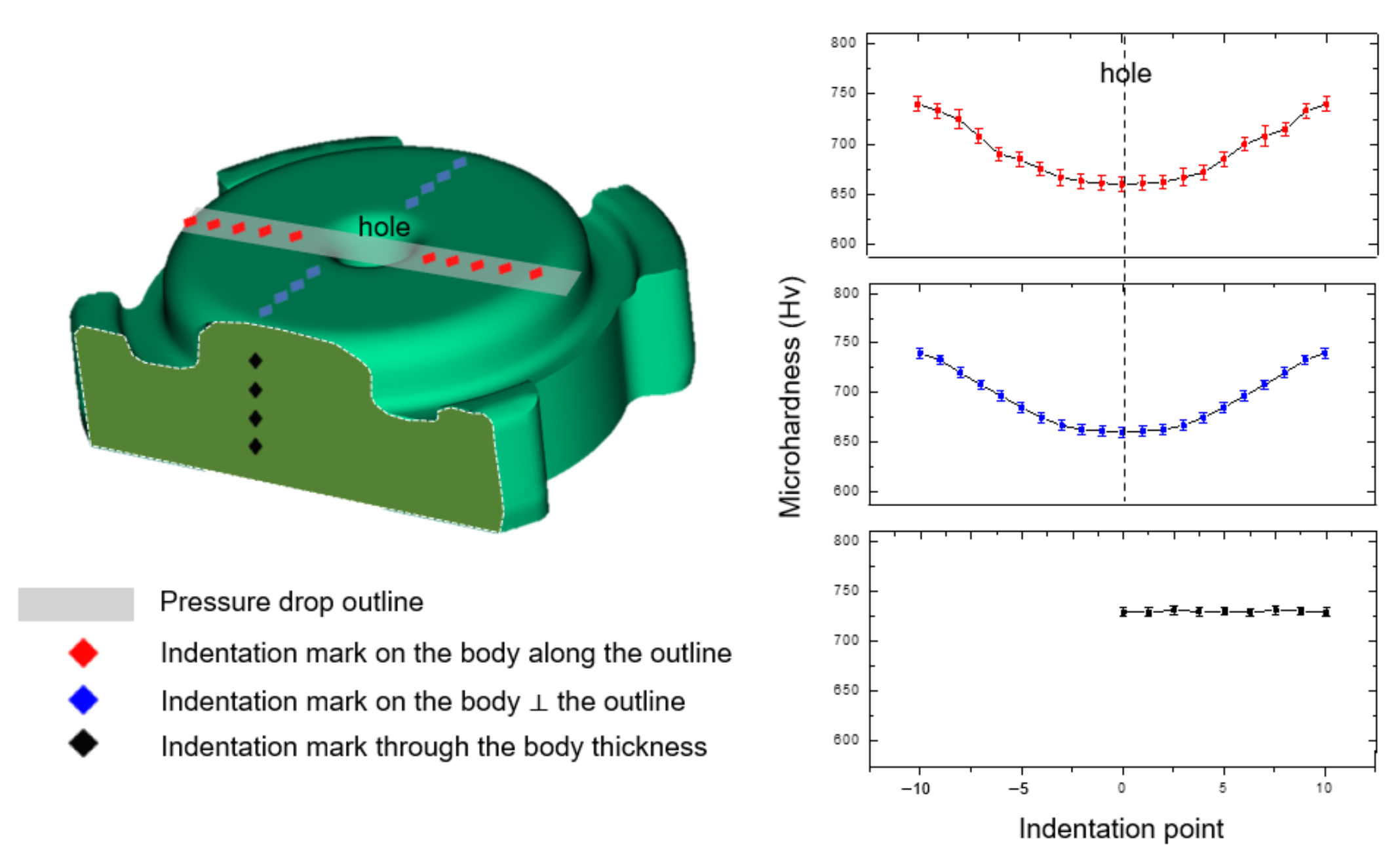
2.5. Hardness Analysis
3. Results and Discussion
3.1. Moldflow Simulation
3.2. Surface Observation
3.3. Three-Dimensional Observation
3.4. Hardness
4. Conclusions
Author Contributions
Funding
Institutional Review Board Statement
Informed Consent Statement
Data Availability Statement
Conflicts of Interest
References
- Ye, H.; Liu, X.Y.; Hong, H. Fabrication of Metal Matrix Composites by Metal Injection Molding-A Review. J. Mater. Process. Technol. 2008, 200, 12–24. [Google Scholar] [CrossRef] [Green Version]
- Singh, G.; Missiaen, J.M.; Bouvard, D.; Chaix, J.M. Additive Manufacturing of 17–4 PH Steel Using Metal Injection Molding Feedstock: Analysis of 3D Extrusion Printing, Debinding and Sintering. Addit. Manuf. 2021, 47, 102287. [Google Scholar] [CrossRef]
- Hamidi, M.F.F.A.; Harun, W.S.W.; Samykano, M.; Ghani, S.A.C.; Ghazalli, Z.; Ahmad, F.; Sulong, A.B. A Review of Biocompatible Metal Injection Moulding Process Parameters for Biomedical Applications. Mater. Sci. Eng. C 2017, 78, 1263–1276. [Google Scholar] [CrossRef] [Green Version]
- Chen, L.J.; Li, T.; Li, Y.M.; He, H.; Hu, Y.H. Porous Titanium Implants Fabricated by Metal Injection Molding. Trans. Nonferrous Met. Soc. China 2009, 19, 1174–1179. [Google Scholar] [CrossRef]
- German, R.M. Progress in Titanium Metal Powder Injection Molding. Materials 2013, 6, 3641–3662. [Google Scholar] [CrossRef] [Green Version]
- Lobo, H. Characterization of Feedstock in Metal Injection Molding (MIM), 2nd ed.; Elsevier Ltd.: Amsterdam, The Netherlands, 2019; ISBN 9780081021521. [Google Scholar]
- Urtekin, L.; Yılan, F.; Uslan, I.; Tuç, B. Effect of Skeleton Binder Change on Rheological Properties for Ceramic Injection Molding. Bilecik Şeyh Edebali Üniversitesi Fen Bilim. Derg. 2022, 9, 314–323. [Google Scholar] [CrossRef]
- Mohamad Nor, N.H.; Muhamad, N.; Ismail, M.H.; Jamaludin, K.R.; Ahmad, S.; Ibrahim, M.H.I. Flow Behaviour to Determine the Defects of Green Part in Metal Injection Molding. Int. J. Mech. Mater. Eng. 2009, 4, 70–75. [Google Scholar]
- Muangwaeng, B.; Rojananan, S.; Rojananan, S. The Effect of Injection Parameters on Morphology in Metal Injection Moulding. Adv. Mater. Res. 2013, 802, 174–178. [Google Scholar] [CrossRef]
- Li, Y.; Li, L.; Khalil, K.A. Effect of Powder Loading on Metal Injection Molding Stainless Steels. J. Mater. Process. Technol. 2007, 183, 432–439. [Google Scholar] [CrossRef]
- Moon, A.P.; Dwarapudi, S.; Sista, K.S.; Kumar, D.; Sinha, G.R. Opportunity and Challenges of Iron Powders for Metal Injection Molding. ISIJ Int. 2021, 61, 2015–2033. [Google Scholar] [CrossRef]
- Bilovol, V.V.; Kowalski, L.; Duszczyk, J.; Katgerman, L. Comparison of Numerical Codes for Simulation of Powder Injection Moulding. Powder Metall. 2003, 46, 55–60. [Google Scholar] [CrossRef]
- Urtekin, L.; Genç, A.; Bozkurt, F. Fabrication and Simulation of Feedstock for Titanium-Powder Injection-Molding Cortical-Bone Screws. Mater. Tehnol. 2019, 53, 619–625. [Google Scholar] [CrossRef]
- Xu, S.; Cao, S.; Hui, J. Mold Optimization Design of Metal Powder Injection Product USB Interface Based on Mold Flow Analysis. IOP Conf. Ser. Earth Environ. Sci. 2019, 267, 032034. [Google Scholar] [CrossRef]
- Barrière, T.; Gelin, J.C.; Liu, B. Improving Mould Design and Injection Parameters in Metal Injection Moulding by Accurate 3D Finite Element Simulation. J. Mater. Process. Technol. 2002, 125–126, 518–524. [Google Scholar] [CrossRef]
- Kang, T.G.; Ahn, S.; Chung, S.H.; Chung, S.T.; Kwon, Y.S.; Park, S.J.; German, R.M. Modeling and Simulation of Metal Injection Molding (MIM). In Handbook of Metal Injection Molding; Woodhead Publishing: Sawston, UK, 2012; pp. 197–234. [Google Scholar] [CrossRef]
- Ghanmi, O.; Demers, V. Molding Properties of Titanium-Based Feedstock Used in Low-Pressure Powder Injection Molding. Powder Technol. 2021, 379, 515–525. [Google Scholar] [CrossRef]
- Wright, M.; Hughes, L.J.; Gressel, S.H. Rheological Characterization of Feedstocks for Metal Injection Molding. J. Mater. Eng. Perform. 1994, 3, 300–306. [Google Scholar] [CrossRef]
- Mohd Zainon, N.; Abdulah, N.; Roslani, N.; Omar, M.A. Tribological Properties of 316L Stainless Steel Fabricated via Metal Injection Molding. Adv. Mater. Res. 2014, 879, 134–138. [Google Scholar] [CrossRef]
- Heaney, D.F.; Greene, C.D. Molding of Components in Metal Injection Molding (MIM), 2nd ed.; Elsevier Ltd.: Amsterdam, The Netherlands, 2019; ISBN 9780081021521. [Google Scholar]
- Safarian, A.; Subaşi, M.; Karataş, Ç. The Effect of Sintering Parameters on Diffusion Bonding of 316L Stainless Steel in Inserted Metal Injection Molding. Int. J. Adv. Manuf. Technol. 2017, 89, 2165–2173. [Google Scholar] [CrossRef]
- Barriere, T.; Liu, B.; Gelin, J.C. Determination of the Optimal Process Parameters in Metal Injection Molding from Experiments and Numerical Modeling. J. Mater. Process. Technol. 2003, 143–144, 636–644. [Google Scholar] [CrossRef]
- Nasir, S.M.; Ismail, K.A.; Shayfull, Z.; Shuaib, N.A. Comparison between Single and Multi Gates for Minimization of Warpage Using Taguchi Method in Injection Molding Process for ABS Material. Key Eng. Mater. 2014, 594–595, 842–851. [Google Scholar] [CrossRef]
- Qayyum, J.A.; Altaf, K.; Rani, A.M.A.; Ahmad, F.; Qadir, H.A.; Amin, W. Metal Injection Molding Process Parameters as A Function of Filling Performance of 3D Printed Polymer Mold. MATEC Web Conf. 2018, 225, 1–6. [Google Scholar] [CrossRef]
- Singh, P.; Balla, V.K.; Gokce, A.; Atre, S.V.; Kate, K.H. Additive Manufacturing of Ti-6Al-4V Alloy by Metal Fused Filament Fabrication (MF3): Producing Parts Comparable to That of Metal Injection Molding. Prog. Addit. Manuf. 2021, 6, 593–606. [Google Scholar] [CrossRef]
- Ibrahim, M.H.I.; Muhamad, N.; Sulong, A.B.; Jamaludin, K.R.; Nor, N.H.M.; Ahmad, S. Optimization of Micro Metal Injection Molding SS 316L for the Highest Green Strength by Using Taguchi Method. Adv. Mater. Res. 2011, 264–265, 135–140. [Google Scholar] [CrossRef]
- Harun, M.R.; Muhamad, N.; Sulong, A.B.; Mohamad Nor, N.H.; Jamaludin, K.R. Metal Injection Moulding of ZK60 Magnesium Alloy Powder Using Palm Stearin Based Binder System. Adv. Mater. Res. 2012, 445, 374–379. [Google Scholar] [CrossRef]
- Dehghan-Manshadi, A.; Bermingham, M.J.; Dargusch, M.S.; StJohn, D.H.; Qian, M. Metal Injection Moulding of Titanium and Titanium Alloys: Challenges and Recent Development. Powder Technol. 2017, 319, 289–301. [Google Scholar] [CrossRef] [Green Version]
- Yang, S.; Zhang, R.; Qu, X. Optimization and Evaluation of Metal Injection Molding by Using X-ray Tomography. Mater. Charact. 2015, 104, 107–115. [Google Scholar] [CrossRef]
- Dekhtyar, A.I.; Bondarchuk, V.I.; Karasevska, O.P.; Oryshych, D.V.; Savvakin, D.G.; Skoryk, M.A. Microstructure Change under Hot Deformation in Zirconium Alloys Synthesized by Powder Metallurgy. Mater. Charact. 2019, 158, 109949. [Google Scholar] [CrossRef]
- Garcea, S.C.; Wang, Y.; Withers, P.J. X-ray Computed Tomography of Polymer Composites. Compos. Sci. Technol. 2018, 156, 305–319. [Google Scholar] [CrossRef]
- Mannschatz, A.; Höhn, S.; Moritz, T. Powder-Binder Separation in Injection Moulded Green Parts. J. Eur. Ceram. Soc. 2010, 30, 2827–2832. [Google Scholar] [CrossRef]
- Jenni, M.; Schimmer, L.; Zauner, R.; Stampfl, J.; Morris, J. Quantitative Study of Powder Binder Separation of Feedstocks. PIM Int. 2008, 2, 50–55. [Google Scholar]
- German, R.M. Homogeneity Effects on Feedstock Viscosity in Powder Injection Molding. J. Am. Ceram. Soc. 1994, 77, 283–285. [Google Scholar] [CrossRef]
- Enneti, R.K.; Onbattuvelli, V.P.; Gulsoy, O.; Kate, K.H.; Atre, S.V. Powder-Binder Formulation and Compound Manufacture in Metal Injection Molding (MIM), 2nd ed.; Elsevier Ltd.: Amsterdam, The Netherlands, 2019; ISBN 9780081021521. [Google Scholar]
- Dutta, G.; Bose, D. Effect of Sintering Temperature on Density, Porosity and Hardness of a Powder Metallurgy Component. Int. J. Emerg. Technol. Adv. Eng. 2012, 2, 121–123. [Google Scholar]
- Cicek, B.; Sun, Y.; Turen, Y.; Ahlatci, H. Investigation of Microstructural Evolution of Gas-Assisted Metal Injection Molded and Sintered Mg-0.5Ca Alloy. Sci. Sinter. 2022, 54, 25–37. [Google Scholar] [CrossRef]


Disclaimer/Publisher’s Note: The statements, opinions and data contained in all publications are solely those of the individual author(s) and contributor(s) and not of MDPI and/or the editor(s). MDPI and/or the editor(s) disclaim responsibility for any injury to people or property resulting from any ideas, methods, instructions or products referred to in the content. |
© 2023 by the authors. Licensee MDPI, Basel, Switzerland. This article is an open access article distributed under the terms and conditions of the Creative Commons Attribution (CC BY) license (https://creativecommons.org/licenses/by/4.0/).
Share and Cite
Widiantara, I.P.; Putri, R.A.K.; Han, D.I.; Bahanan, W.; Lee, E.H.; Woo, C.H.; Kang, J.-H.; Ryu, J.; Ko, Y.G. Characterization of Green Part of Steel from Metal Injection Molding: An Analysis Using Moldflow. Materials 2023, 16, 2516. https://doi.org/10.3390/ma16062516
Widiantara IP, Putri RAK, Han DI, Bahanan W, Lee EH, Woo CH, Kang J-H, Ryu J, Ko YG. Characterization of Green Part of Steel from Metal Injection Molding: An Analysis Using Moldflow. Materials. 2023; 16(6):2516. https://doi.org/10.3390/ma16062516
Chicago/Turabian StyleWidiantara, I Putu, Rosy Amalia Kurnia Putri, Da In Han, Warda Bahanan, Eun Hye Lee, Chang Hoon Woo, Jee-Hyun Kang, Jungho Ryu, and Young Gun Ko. 2023. "Characterization of Green Part of Steel from Metal Injection Molding: An Analysis Using Moldflow" Materials 16, no. 6: 2516. https://doi.org/10.3390/ma16062516