
Exploring High-Precision Non-Assembly Mechanisms: Design of a Vitrectome Mechanism for Eye Surgery
 , and
, and
Abstract
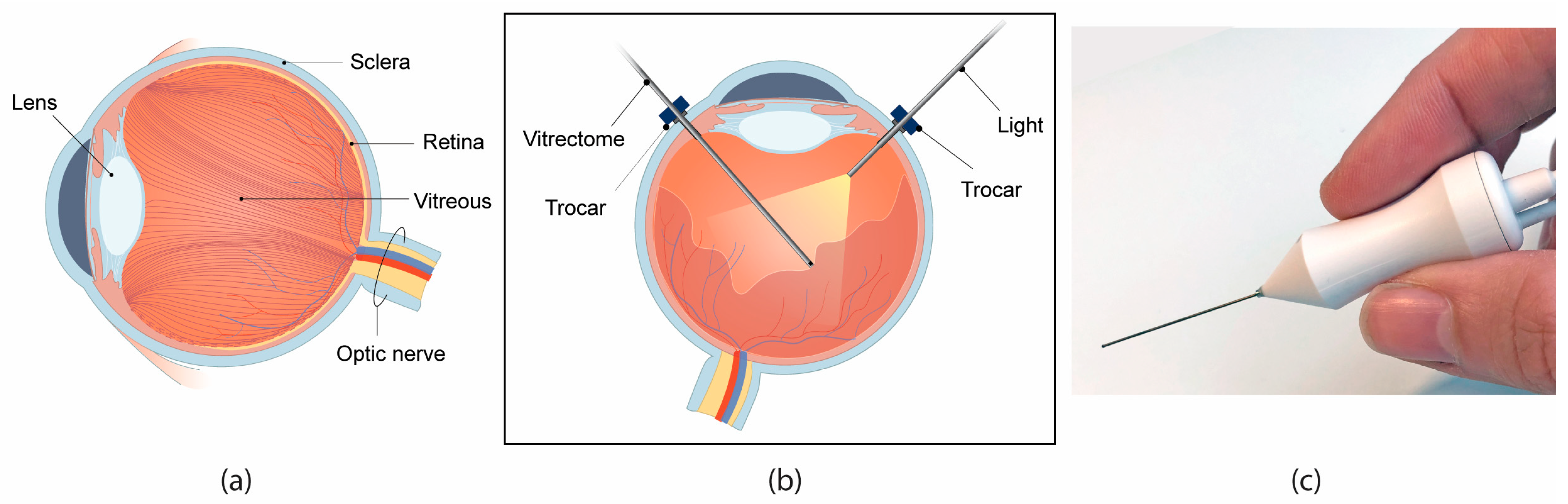
:1. Introduction
2. Design and Fabrication
2.1. Specifications
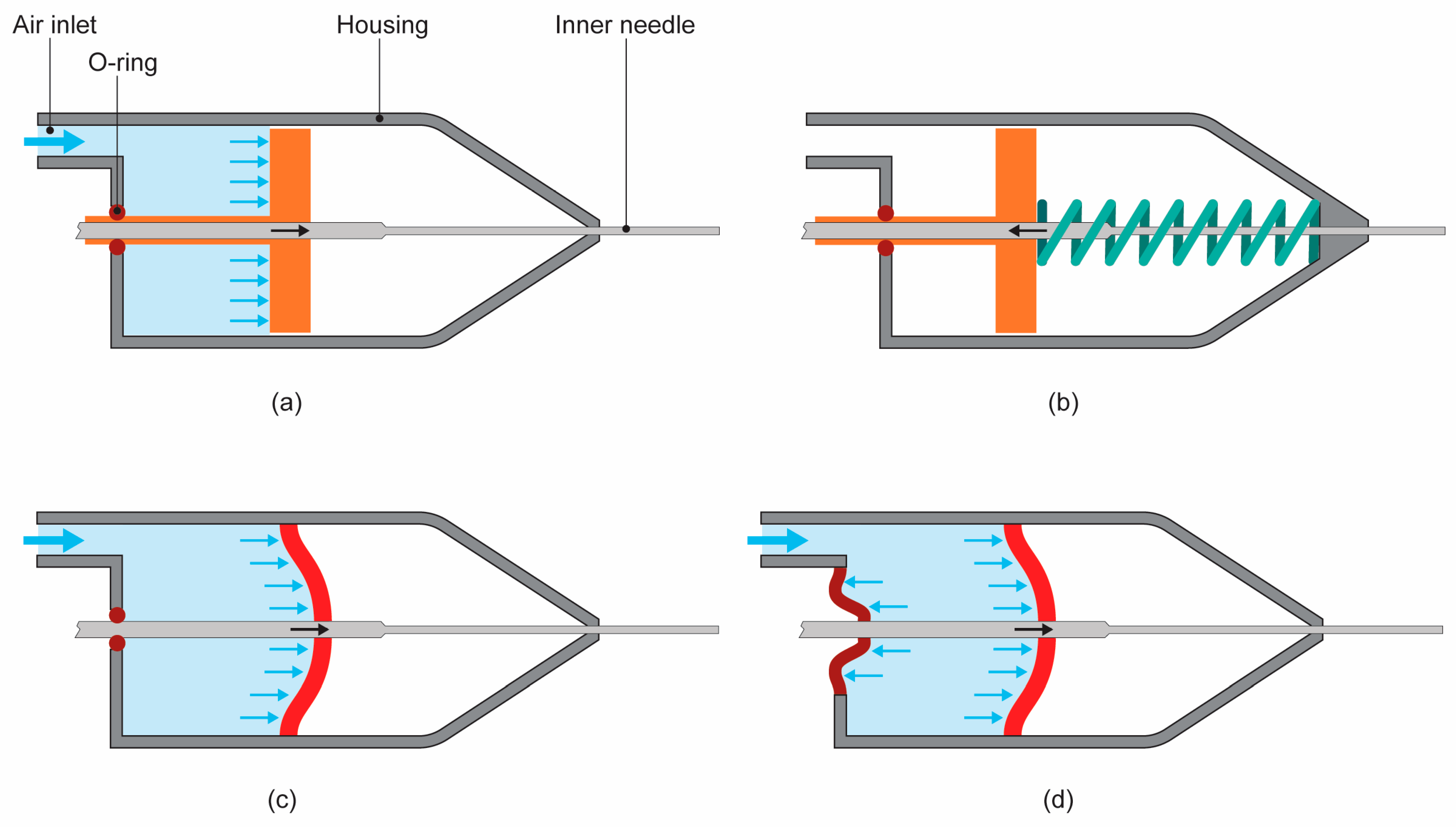
2.2. Driving Mechanism
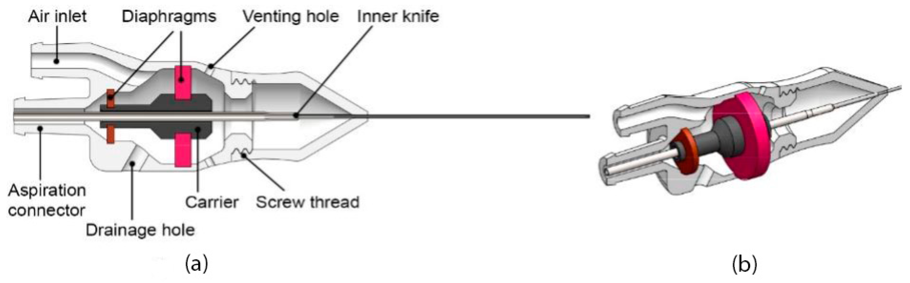
2.2.1. Design
2.2.2. Working Principle
2.3. 3D Print Technology
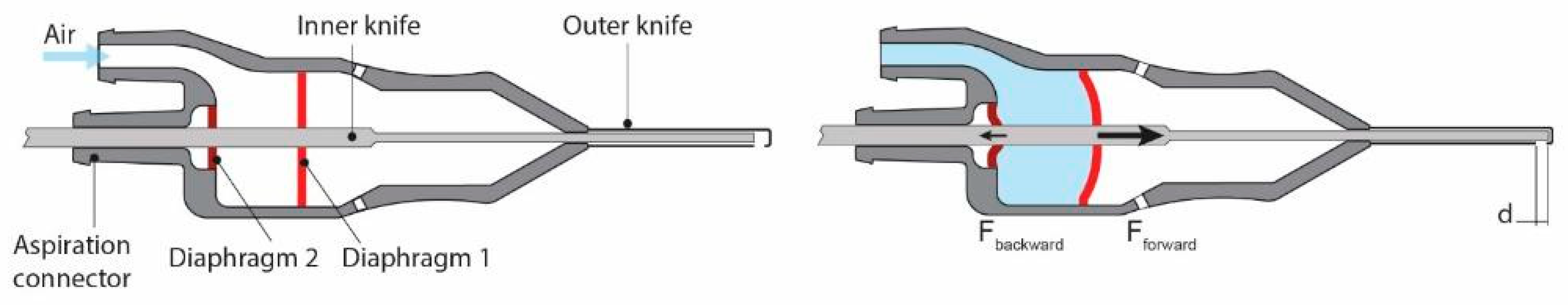
2.4. Non-Assembly Vitrectome Design
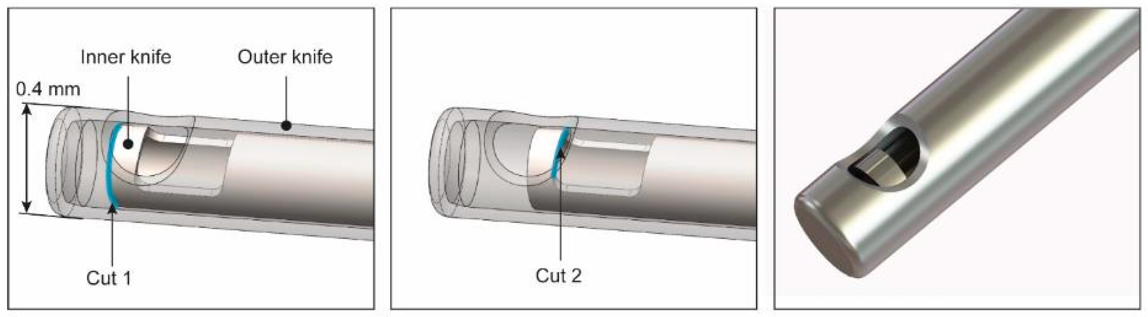
2.4.1. Knives
2.4.2. Main Body and Housing
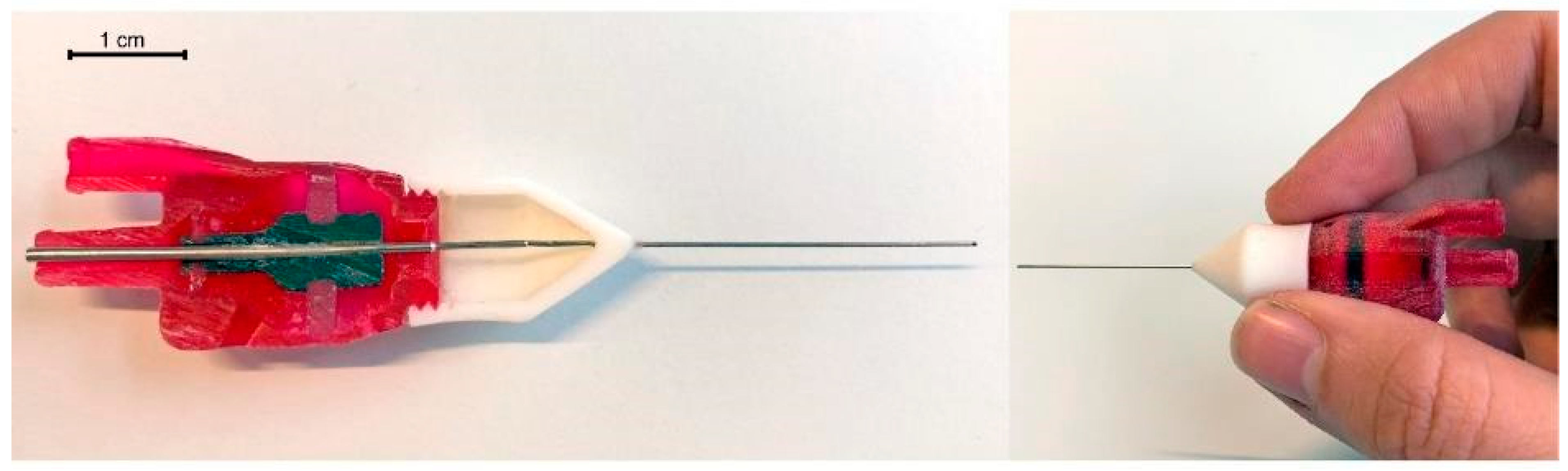
2.4.3. Initial Prototype
3. Experimental Evaluation
3.1. Diaphragm Requirements
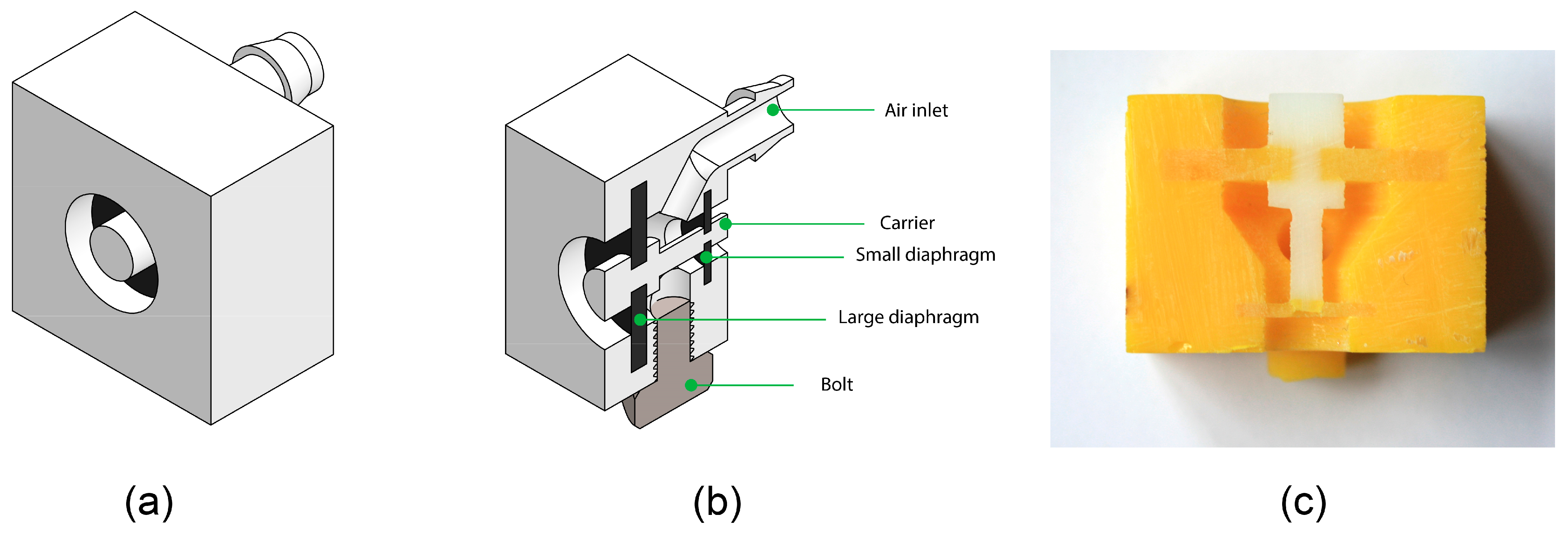
3.2. Prototype Design and Production
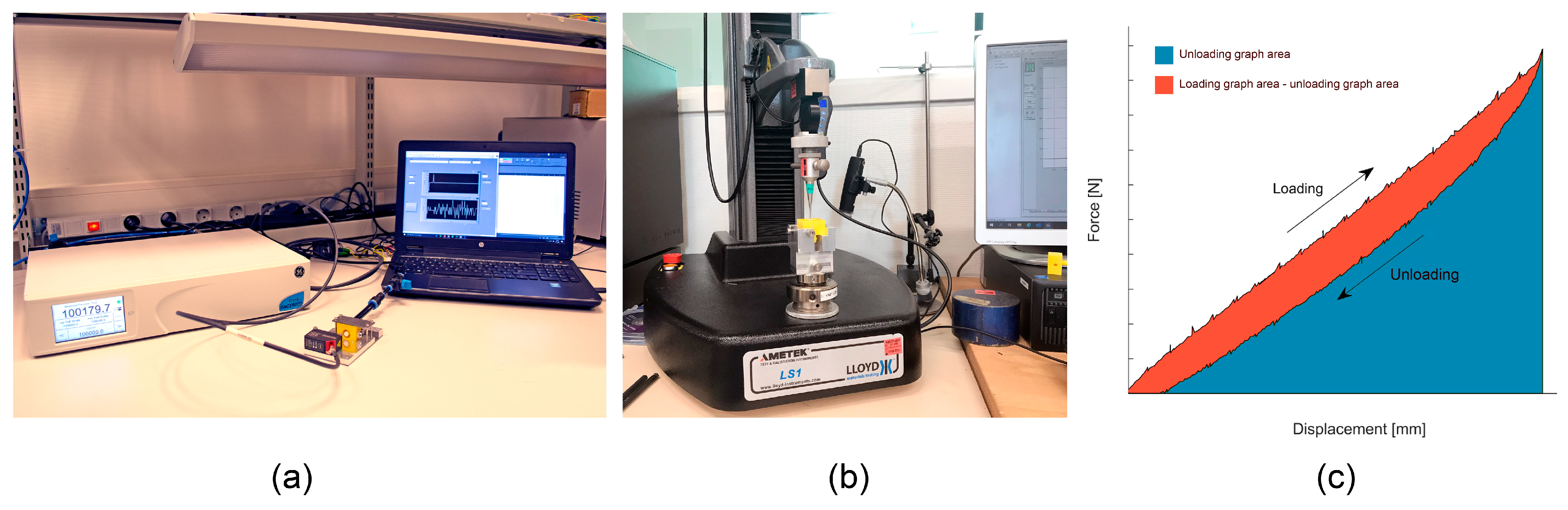
3.3. Experimental Design and Procedure
3.3.1. Forward Cutting Force
3.3.2. Backward Cutting Force and Spring Coefficient
3.3.3. Cutting Speed
3.4. Digital Material Diaphragms
3.4.1. Design
3.4.2. Results
3.5. Spring Reinforced Diaphragms
3.5.1. Design
3.5.2. Results
4. Discussion
4.1. Production
4.2. Performance
4.2.1. Cutting Force
4.2.2. Cutting Speed
4.2.3. Materials and Design
4.3. Limitations of the Tests
4.4. Future Design Directions
5. Conclusions
Author Contributions
Funding
Institutional Review Board Statement
Informed Consent Statement
Data Availability Statement
Acknowledgments
Conflicts of Interest
References
- Snell, R.S.; Lemp, M.A. Clinical Anatomy of the Eye; Blackwell Science Ltd.: Oxford, UK, 1997; ISBN 9781118690987. [Google Scholar]
- Ahmed, Z.; Lutty, G.A. Anti-Angiogenic Properties of Vitreous. In Reference Module in Neuroscience and Biobehavioral Psychology; Elsevier: Amsterdam, The Netherlands, 2017; pp. 112–119. ISBN 9780128093245. [Google Scholar]
- Le Goff, M.M.; Bishop, P.N. Adult vitreous structure and postnatal changes. Eye 2008, 22, 1214–1222. [Google Scholar] [CrossRef] [Green Version]
- Hansen, H.N.; Arentoft, M.; Tosello, G. Micro-mechanical Assembly. In Micromanufacturing Engineering and Technology; Elsevier: Amsterdam, The Netherlands, 2015; pp. 581–595. ISBN 978-0-323-31149-6. [Google Scholar]
- Gibson, I.; Rosen, D.; Stucker, B. Additive Manufacturing Technologies; Springer: New York, NY, USA, 2015; ISBN 978-1-4939-2112-6. [Google Scholar]
- Culmone, C.; Smit, G.; Breedveld, P. Additive manufacturing of medical instruments: A state-of-the-art review. Addit. Manuf. 2019, 27, 461–473. [Google Scholar] [CrossRef]
- Culmone, C.; Henselmans, P.W.J.; van Starkenburg, R.I.B.; Breedveld, P. Exploring non-assembly 3D printing for novel compliant surgical devices. PLoS ONE 2020, 15, e0232952. [Google Scholar] [CrossRef] [PubMed]
- Castledine, N.P.; Boyle, J.H.; Kim, J. Design of a Modular Continuum Robot Segment for use in a General Purpose Manipulator. In Proceedings of the 2019 International Conference on Robotics and Automation (ICRA), Montreal, QC, Canada, 20–24 May 2019; IEEE: New York, NY, USA, 2019; pp. 4430–4435. [Google Scholar]
- Hu, Y.; Zhang, L.; Li, W.; Yang, G.-Z. Design and Fabrication of a 3-D Printed Metallic Flexible Joint for Snake-Like Surgical Robot. IEEE Robot. Autom. Lett. 2019, 4, 1557–1563. [Google Scholar] [CrossRef]
- Roppenecker, D.B.; Pfaff, A.; Coy, J.A.; Lueth, T.C. Multi arm snake-like robot kinematics. In Proceedings of the 2013 IEEE/RSJ International Conference on Intelligent Robots and Systems, Tokyo, Japan, 3–7 November 2013; IEEE: New York, NY, USA, 2013; pp. 5040–5045. [Google Scholar]
- Leeflang, S.; Janbaz, S.; Zadpoor, A.A. Metallic clay. Addit. Manuf. 2019, 28, 528–534. [Google Scholar] [CrossRef]
- Leeflang, M.A.; Bobbert, F.S.L.; Zadpoor, A.A. Additive manufacturing of non-assembly deployable mechanisms for the treatment of large bony defects. Addit. Manuf. 2021, 46, 102194. [Google Scholar] [CrossRef]
- Lussenburg, K.; Scali, M.; Sakes, A.; Breedveld, P. Additive Manufacturing of a Miniature Functional Trocar for Eye Surgery. Front. Med. Technol. 2022, 4, 842958. [Google Scholar] [CrossRef]
- Navajas, E.V.; ten Hove, M. Three-Dimensional Printing of a Transconjunctival Vitrectomy Trocar-Cannula System. Ophthalmologica 2017, 237, 119–122. [Google Scholar] [CrossRef]
- Zanaty, M.; Fussinger, T.; Rogg, A.; Lovera, A.; Lambelet, D.; Vardi, I.; Wolfensberger, T.J.; Baur, C.; Henein, S. Programmable Multistable Mechanisms for Safe Surgical Puncturing. J. Med. Device 2019, 13, 021002. [Google Scholar] [CrossRef]
- Alting, L.; Kimura, F.; Hansen, H.N.; Bissacco, G. Micro Engineering. CIRP Ann. 2003, 52, 635–657. [Google Scholar] [CrossRef]
- Comaratta, M.; Hariprasad, S.M.; Reddy, R. The Evolution of Vitreoretinal Surgery Platforms. Ophthalmic Surg. Lasers Imaging Retin. 2017, 48, 532–538. [Google Scholar] [CrossRef] [PubMed] [Green Version]
- de Oliveira, P.R.C.; Berger, A.R.; Chow, D.R. Vitreoretinal instruments: Vitrectomy cutters, endoillumination and wide-angle viewing systems. Int. J. Retin. Vitr. 2016, 2, 1–15. [Google Scholar] [CrossRef] [PubMed] [Green Version]
- Barnes, A.C.; DeBoer, C.M.; Bhadri, P.R.; Magalhaes, O.; Kerns, R.M.; McCormick, M.T.; Chong, L.P.; Humayun, M.S. 25-Gauge Instrumentation: Engineering Challenges and Tradeoffs; Springer: Berlin/Heidelberg, Germany, 2009; pp. 9–29. [Google Scholar]
- Teixeira, A.; Chong, L.P.; Matsuoka, N.; Arana, L.; Kerns, R.; Bhadri, P.; Humayun, M. Vitreoretinal Traction Created by Conventional Cutters during Vitrectomy. Ophthalmology 2010, 117, 1387–1392.e2. [Google Scholar] [CrossRef] [PubMed]
- Rizzo, S.; Genovesi-Ebert, F.; Belting, C. Comparative study between a standard 25-gauge vitrectomy system and a new ultrahigh-speed 25-gauge system with duty cycle control in the treatment of various vitreoretinal diseases. Retina 2011, 31, 2007–2013. [Google Scholar] [CrossRef] [PubMed]
- Stratasys, PolyJet Parts On Demand. 2022. Available online: https://www.stratasys.com/en/stratasysdirect/technologies/3d-printing/polyjet/ (accessed on 27 September 2022).
- Pilipović, A.; Raos, P.; Šercer, M. Experimental analysis of properties of materials for rapid prototyping. Int. J. Adv. Manuf. Technol. 2009, 40, 105–115. [Google Scholar] [CrossRef]
- Barclift, M.W.; Williams, C.B. Examining variability in the mechanical properties of parts manufactured via polyjet direct 3d printing. In Proceedings of the International Solid Freeform Fabrication Symposium, Austin, TX, USA, 6–8 August 2012. [Google Scholar]
- Kęsy, A.; Kotliński, J. Mechanical properties of parts produced by using polymer jetting technology. Arch. Civ. Mech. Eng. 2010, 10, 37–50. [Google Scholar] [CrossRef]
- Mueller, J.; Kim, S.E.; Shea, K.; Daraio, C. Tensile Properties of Inkjet 3D Printed Parts: Critical Process Parameters and Their Efficient Analysis. In Proceedings of the Volume 1A: 35th Computers and Information in Engineering Conference, Boston, MA, USA, 2–5 August 2015; American Society of Mechanical Engineers: New York, NY, USA, 2015. [Google Scholar]
- Blanco, D.; Fernandez, P.; Noriega, A. Nonisotropic experimental characterization of the relaxation modulus for PolyJet manufactured parts. J. Mater. Res. 2014, 29, 1876–1882. [Google Scholar] [CrossRef]
- Reichl, K.K.; Inman, D.J. Dynamic Mechanical and Thermal Analyses of Objet Connex 3D Printed Materials. Exp. Tech. 2018, 42, 19–25. [Google Scholar] [CrossRef]
- Meisel, N.; Williams, C. An Investigation of Key Design for Additive Manufacturing Constraints in Multimaterial Three-Dimensional Printing. J. Mech. Des. 2015, 137, 111406. [Google Scholar] [CrossRef]
- Materialise, Design Guidelines for Composite Materials | PolyJet. 2022. Available online: https://www.materialise.com/en/academy/industrial/design-am/composite-materials (accessed on 3 October 2022).
- Parise, J.J.; Howell, L.L.; Magleby, S.P. Ortho-Planar Linear-Motion Springs. Mech. Mach. Theory 2001, 36, 1281. Available online: https://scholarsarchive.byu.edu/facpub%20 (accessed on 17 January 2022). [CrossRef] [Green Version]
- Teichert, G.H.; Jensen, B.D. Design and fabrication of a fully-compliant mechanism for control of cellular injection arrays. Prod. Eng. 2013, 7, 561–568. [Google Scholar] [CrossRef]
- Muthuram, N.; Sriram Madhav, P.; Keerthi Vasan, D.; Mohan, M.E.; Prajeeth, G. A review of recent literatures in poly jet printing process. Mater. Today Proc. 2022, 68, 1906–1920. [Google Scholar] [CrossRef]
- Childs, E.H.; Latchman, A.V.; Lamont, A.C.; Hubbard, J.D.; Sochol, R.D. Additive Assembly for PolyJet-Based Multi-Material 3D Printed Microfluidics. J. Microelectromech. Syst. 2020, 29, 1094–1096. [Google Scholar] [CrossRef]
- Giovanni, M. Di Flat and Corrugated Diaphragm Design Handbook; M. Dekker: New York, NY, USA, 1982; ISBN 9780824712815. [Google Scholar]


| Name | Composition Vero | Composition Agilus30 | Stiffness Indication |
|---|---|---|---|
| 80Agilus20Vero | 20% | 80% | flexible |
| 50Agilus50Vero | 50% | 50% | medium |
| 20Agilus80Vero | 80% | 20% | stiff |
| Prototype Name (Stiffness Indication) | Backward Cutting Force (n = 18) | Spring Coefficient (n = 18) | Pressure to Reach 0.8 mm Displacement (n = 2) | Fastest Forward Response 0.8 mm (n = 1) | Fastest Backward Response 0.8 mm (n = 1) |
|---|---|---|---|---|---|
| 20Agilus80Vero (stiff) | 8.9 ± 0.92 N | 11.7 ± 1.53 N/mm | 257 kPa | 0.567 s | 30.5 s |
| 50Agilus50Vero (medium) | 3.6 ± 0.27 N | 5.2 ± 0.28 N/mm | 171 kPa | 0.156 s | 9.7 s |
| 80Agilus20Vero (flexible) | 3.3 ± 0.16 N | 4.5 ± 0.18 N/mm | 156 kPa | 0.110 s | 9.2 s |
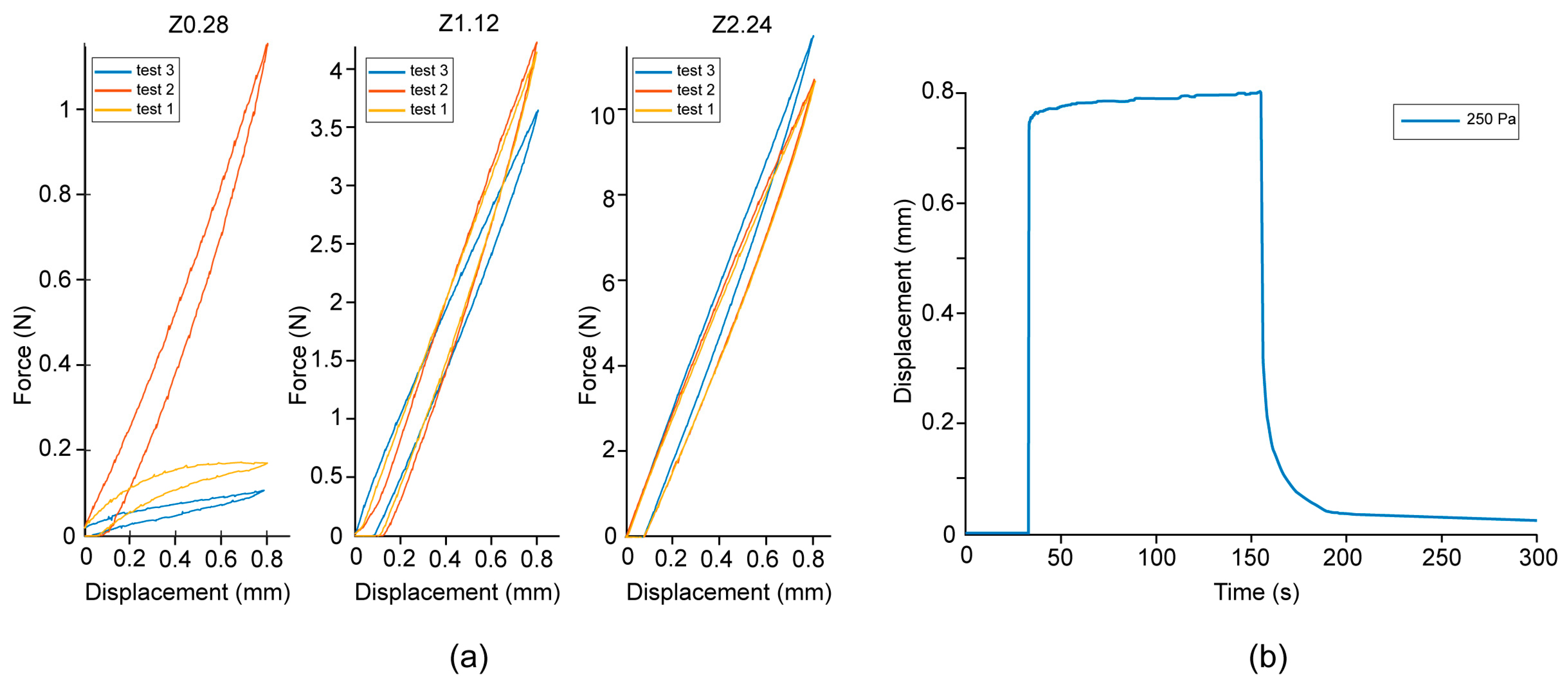
| Name | Thickness Spring | Material Spring | Thickness Membrane | Material Membrane |
|---|---|---|---|---|
| Z0.28 | 0.28 mm | 100% Vero | 0.50 mm | 100% Agilus30 |
| Z1.12 | 1.12 mm | 100% Vero | 0.50 mm | 100% Agilus30 |
| Z2.24 | 2.24 mm | 100% Vero | 0.50 mm | 100% Agilus30 |
| Name | Backward Cutting Force (n = 3) | Spring Coefficient (n = 3) | Fastest Forward Response 0.8 mm (n = 1) | Fastest Backward Response 0.8 mm (n = 1) |
|---|---|---|---|---|
| Z0.28 | 0.48 ± 0.48 N | 0.6 ± 0.60 N/mm | - | - |
| Z1.12 | 4.00 ± 0.25 N | 5.0 ± 0.32 N/mm | 37.7 s | 47.0 s |
| Z2.24 | 11.01 ± 0.49 N | 13.8 ± 0.61 N/mm | 3.1 s | - |
| Name | Fastest Response between 0 and 0.4 mm Forward (n = 1) | Fastest Response between 0.6 and 0.2 mm Backward (n = 1) |
|---|---|---|
| Z0.28 | 0.0019 s | 0.4 s |
| Z1.12 | 0.0070 s | 5.4 s |
| Z2.24 | 0.0056 s | 2.5 s |
Disclaimer/Publisher’s Note: The statements, opinions and data contained in all publications are solely those of the individual author(s) and contributor(s) and not of MDPI and/or the editor(s). MDPI and/or the editor(s) disclaim responsibility for any injury to people or property resulting from any ideas, methods, instructions or products referred to in the content. |
© 2023 by the authors. Licensee MDPI, Basel, Switzerland. This article is an open access article distributed under the terms and conditions of the Creative Commons Attribution (CC BY) license (https://creativecommons.org/licenses/by/4.0/).
Share and Cite
Lussenburg, K.; Scali, M.; Stolk, M.; Robijns, D.; Sakes, A.; Breedveld, P. Exploring High-Precision Non-Assembly Mechanisms: Design of a Vitrectome Mechanism for Eye Surgery. Materials 2023, 16, 1772. https://doi.org/10.3390/ma16051772
Lussenburg K, Scali M, Stolk M, Robijns D, Sakes A, Breedveld P. Exploring High-Precision Non-Assembly Mechanisms: Design of a Vitrectome Mechanism for Eye Surgery. Materials. 2023; 16(5):1772. https://doi.org/10.3390/ma16051772
Chicago/Turabian StyleLussenburg, Kirsten, Marta Scali, Maarten Stolk, Daisy Robijns, Aimée Sakes, and Paul Breedveld. 2023. "Exploring High-Precision Non-Assembly Mechanisms: Design of a Vitrectome Mechanism for Eye Surgery" Materials 16, no. 5: 1772. https://doi.org/10.3390/ma16051772