
Predicting Flexible Pavement Distress and IRI Considering Subgrade Resilient Modulus of Fine-Grained Soils Using MEPDG

Department of Civil and Environmental Engineering, University of South Carolina, Columbia, SC 29208, USA
*
Author to whom correspondence should be addressed.
Materials 2023, 16(3), 1126; https://doi.org/10.3390/ma16031126
Submission received: 8 December 2022
/
Revised: 10 January 2023
/
Accepted: 24 January 2023
/
Published: 28 January 2023
(This article belongs to the Special Issue Sustainable Asphalt Pavements: Materials, Design Methods, and Characterization Techniques (Second Volume))
Abstract
:This paper highlights the subgrade resilient modulus (MR), which is recognized as an important parameter to characterize the stiffness of the subgrade soil for designing flexible pavement. In this study, 18 thin-walled Shelby tube samples of fine-grained subgrade soils were collected from two sites in South Carolina (Laurens/SC-72 and Pickens/SC-93) and tested in the laboratory using AASHTO T307-99 to obtain the MR. In addition, falling weight deflectometer (FWD) tests were performed on the same pavement sections to obtain the back-calculated MR(FWD) per the AASHTOWare 2017 back-calculation tool. A subgrade MR catalog was established and used to select hierarchical Input Level 2 for Pavement Mechanistic-Empirical design (PMED) analysis (v 2.6.1). The PMED analysis was run for 20 years. The Mechanistic-Empirical Pavement Design Guide (MEPDG) and global calibration values were used to predict asphalt concrete (AC) pavement distresses (e.g., rutting, bottom-up fatigue, top-down fatigue, and transverse cracking) and International Roughness Index (IRI) for each pavement section. The predicted values were compared to the field-measured values to determine bias and the standard error of the estimate to validate each distress prediction model for local calibration.
1. Introduction
The Mechanistic-Empirical Pavement Design (MEPDG) is based on mechanistic-empirical principles [1,2,3]. These principles are used to calculate pavement responses (stresses, strains, and deflections), and those responses are used to compute incremental damage over time. The MEPDG and newly updated AASHTOWare Pavement ME Design (PMED) software (v2.6.1) require over 100 inputs to model traffic, climate, materials, and pavement to predict the progression of key pavement distresses and smoothness loss over the pavement design period. Pavement performance/distress is primarily concerned with structural and functional performance. The structural performance relates to its physical condition (such as fatigue cracking and rutting for flexible pavements). Ride quality is the dominant characteristic of functional performance, as measured by the International Roughness Index (IRI). In MEPDG, IRI is estimated incrementally over the entire design period by incorporating distresses such as cracking, rutting, faulting, and punchouts as the major factors influencing the loss of smoothness of pavement [1,2,3].
Numerous studies have been performed to predict pavement distress and IRI for flexible pavement using the MEPDG [4,5,6,7]. Different traffic [8,9,10], materials [11,12,13,14], and climate inputs [5,15,16] have an influence on pavement distress and IRI in the MEPDG. Among the inputs of unbound subgrade materials, the MR significantly affects permanent deformation or pavement rutting [17]. MR represents the pavement’s unbound layer configuration’s stiffness subjected to repeated traffic loading. Typically, higher MR soils show less pavement distress and IRI [6,18]. However, some mixed soils (i.e., silty sands and sandy silts) exhibit high resilience and still yield significant rutting [19]. Therefore, it is necessary to correlate resilient modulus with asphalt concrete (AC) pavement distress and IRI for fine-grained soils.
The study will be focused on flexible pavement performance distress and IRI using three different subgrade resilient modulus. Using currently available PMED software (v2.6.1), the outcome of this study will be compared with the field-measured value to assess the estimate’s local bias and standard error.
2. Objectives
The research objectives of this study are to find the potential correlations between asphalt concrete (AC) pavement distresses and subgrade resilient modulus (MR) using the AASHTOWare Pavement ME design in South Carolina. The potential correlations can be adapted to create a subgrade resilient modulus catalog for flexible pavement design for South Carolina and sites with similar soil conditions. The pavement distresses to be correlated in this study include permanent deformation of the AC layer, permanent deformation of the total pavement, thermal cracking, bottom-up fatigue cracking, top-down fatigue cracking, and IRI. To fulfill the objectives of this study, two main research questions are addressed in this investigation: 1. How does subgrade MR affect the predicted distresses and IRI for AC design per PMED (v2.6.1)? & 2. How do these predictions change for different asphalt thicknesses?
3. Methodology
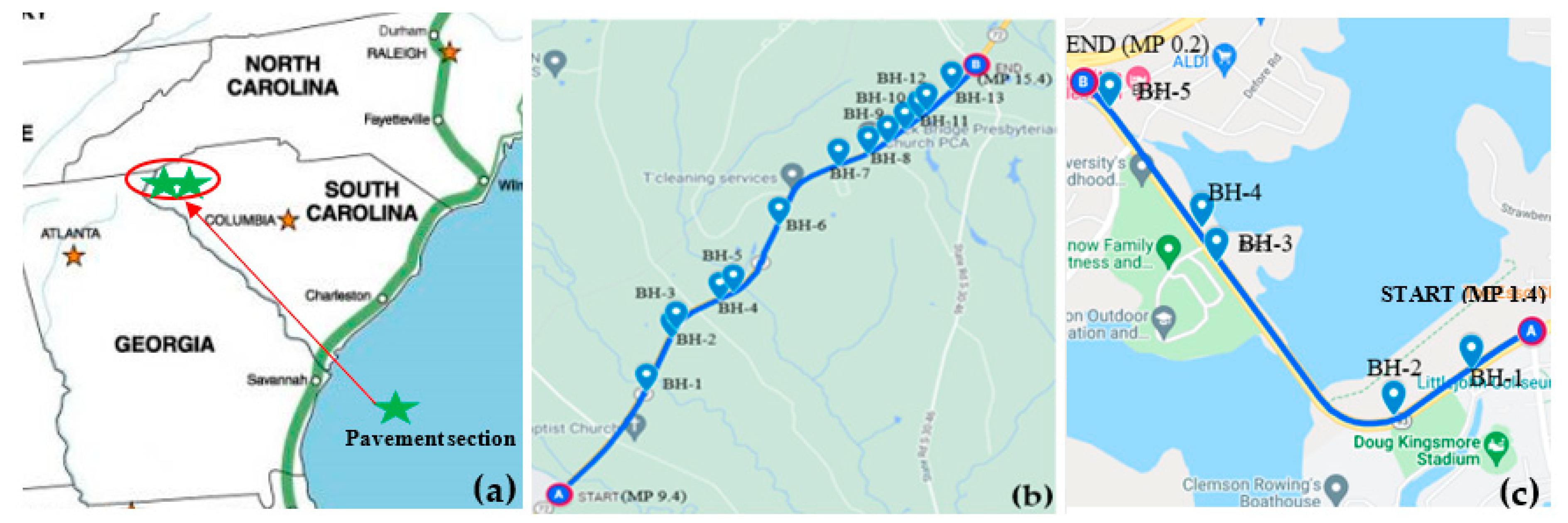
The main variable to be investigated in this study is the subgrade resilient modulus, MR, that will be used to predict pavement distress and IRI using the AASHTOWare PMED software (v2.6.1). The subgrade modulus value was obtained using three different methods: back-calculated MR from field non-destructive test (i.e., FWD) (MR(FWD)), laboratory-measured MR conducted in the laboratory (MR(Lab)), and using the default value based on soil classification (MR(Default)). Non-destructive FWD tests were performed, and MR was back-calculated from the field deflection data [20]. Subgrade soil samples were collected at each FWD test location, and resilient modulus tests were performed using AASHTO T307 [21]. Data for two sites in South Carolina were used in this study (See Figure 1a): Laurens/SC-72 and Pickens/SC-93, where design drawings are available to obtain the pavement layer profile and measurements of pavement distresses have been obtained.
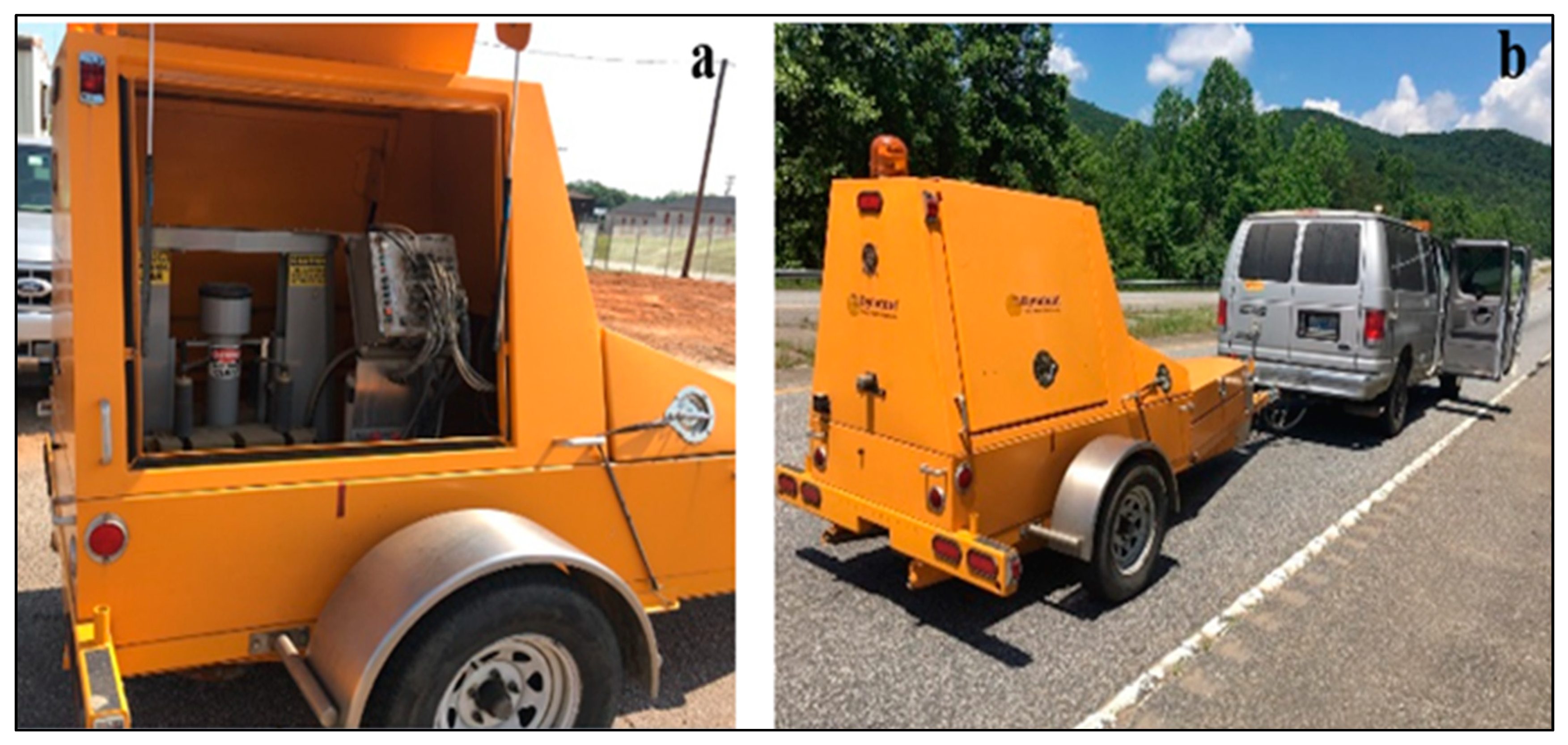
There were 18 coring locations utilized in this study. As shown in Figure 1b,c, 13 coring locations (BH-1 to BH-13) were situated along the 9.8 km pavement section of Laurens/ SC-72, and 5 (BH-1 to BH-5) were located along a 1.9 km section of Pickens/SC-93. At each site, coring began at the “START,” and the pavement was cored at spacings of 305 to 915 m intervals along the pavement surface. Core locations were selected based on the surface appearance of the pavement so that cores could be taken from locations where distresses and no distresses were observed. Subgrade soil samples were collected to a depth ranging from 0.91 to 1.9 m from the bottom of the pavement, depending on site conditions. Boreholes were terminated when the strong gravelly layers were encountered, which made sampling difficult. Thin-walled Shelby tube samples (undisturbed) of the subgrade soil were collected using a jeep jack (see Figure 2a) to remove the Shelby tube at a constant rate in the vertical direction. The tube samples were used to determine the resilient modulus per AASHTO T307. A hand auger collected bulk samples from each borehole (see Figure 2b,c).
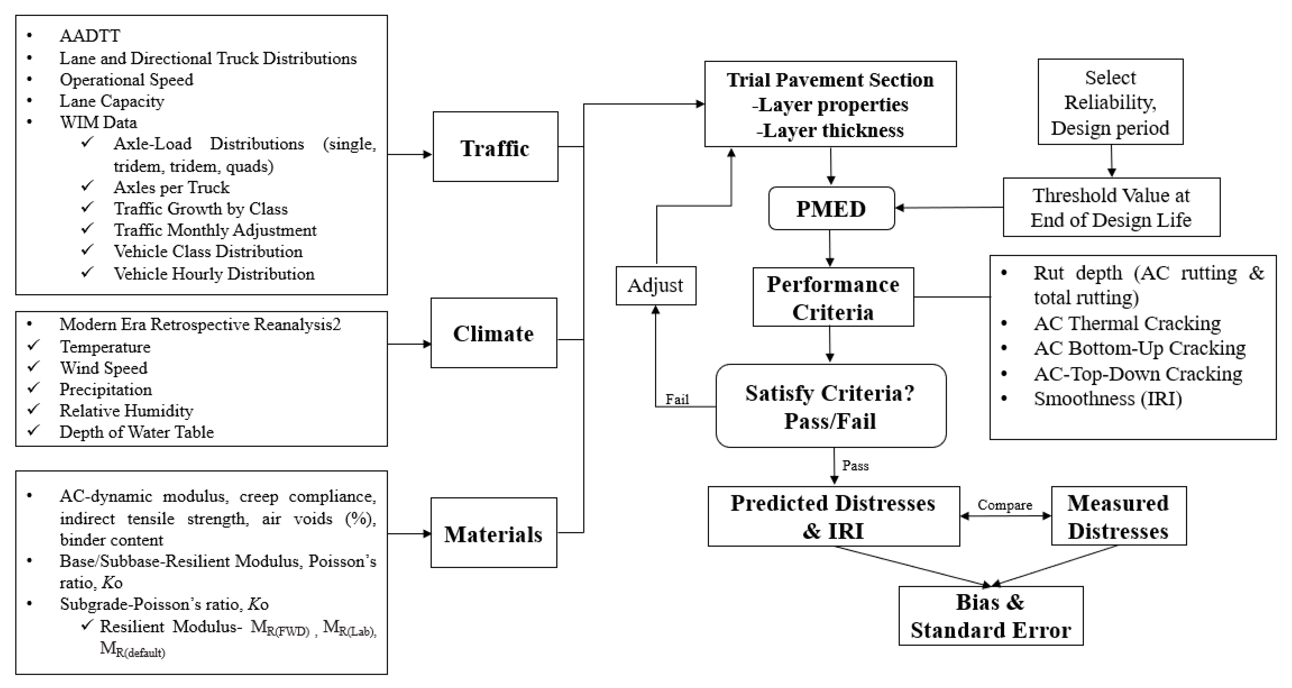
The flow chart of the study organization is shown in Figure 3. The traffic, climate, and materials parameters for each site, except for the subgrade MR, were obtained and held constant in the analysis. The trial pavement section is analyzed incrementally over time using the pavement response and distress models. The pavement passes if the Achieved Reliability is greater than the Target Reliability. If the reverse is true, the pavement fails. If any key distress/performance criteria fail, the trial design needs to be re-run by increasing the AC layer thickness until the requirements are satisfied. Using the PMED software (v2.6.1), PMED predicts distresses in each trial pavement section based on subgrade MR values and compares them to the measured filed values. Global calibration coefficients were used in this study.
3.1. Backcalculated FWD Tests
FWD tests were performed at intervals of approximately 61 m; that is, 157 locations along Laurens/SC-72 and 36 locations along Pickens/SC-93. The FWD tests were performed using the Dynatest system [22]. The apparatus (see Figure 4a,b) consists of seven sensors at seven different offsets (0, 203, 305, 457, 610, 915, and 1194 mm from the loading plate). Each FWD test was performed by applying an impulse load of four different magnitudes (30.5, 40, 54, and 70 kN) and collecting deflection data within the deflection basin [23]. Information on the pavement condition (e.g., layer modulus) can be extracted from the analysis of the deflection data. The layer modulus determined from known FWD data is termed the backcalculated modulus, backcalculated MR, or MR(FWD).
3.2. Resilient Modulus Tests
Resilient modulus (MR) tests were performed in the laboratory on 76 mm diameter by 152 mm long specimens obtained from thin-walled Shelby tubes. A GDS Advanced Dynamic Triaxial Testing System was used to perform the tests per AASHTO T 307. The total load cycle duration for each of the 0-15 sequences (AASHTO T 307) was 1 s, which includes a 0.1-s load duration and a 0.9-s rest period.
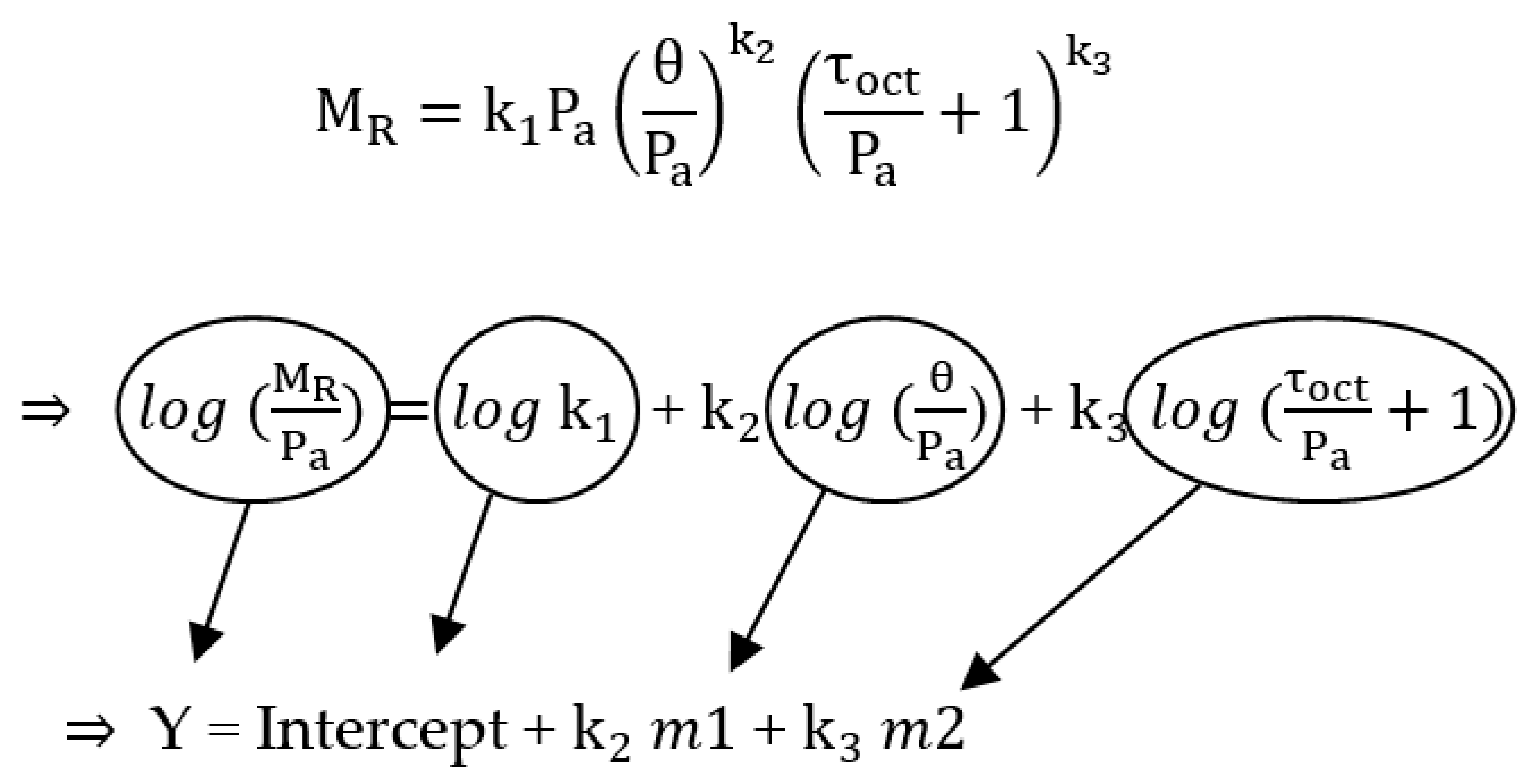
For conditioning sequence No. 0, a minimum of 500 repetitions of a load equivalent to a maximum axial stress of 27.6 kPa and corresponding cyclic stress of 24.8 kPa was applied to the specimen (AASHTO T 307). If the sample was still decreasing in height at the end of the conditioning period, stress cycling was continued up to 1000 repetitions. After the initial conditioning was completed, each of the 15 main test sequences was applied in 100 load repetitions. The average recoverable deformation for the last five cycles of each test was recorded. For each of the three confining pressures (41.4 kPa, 27.6 kPa, 13.8 kPa), five different cyclic stresses (12.4 kPa, 24.8 kPa, 37.3 kPa, 49.7 kPa, 62 kPa) were applied to the sample. The generalized constitutive resilient modulus model was used to calculate MR (NCHRP-1-37A, 2004):
where
MR = resilient modulus value
, and = model parameters
Pa = atmospheric pressure (101.325 kPa)
θ = bulk stress = (σ1 + σ2 + σ3) = (3σ3 + σd)
σ1, σ2, and σ3 = principal stresses and
σ2 = σ3 and σd = deviator (cyclic) stress = σ1 − σ3; and
= octahedral shear stress
=
After completing the resilient modulus test procedure, the MR was calculated for each sequence per AASHTO T307. For determining , , and , Equation (1) was simplified and transferred to the logarithmic function (See Figure 5). The model parameters were obtained for each test using multiple linear regression techniques and used in Equation (1) to calculate the MR for each specimen.
The laboratory-measured resilient modulus (MR(Lab)) was calculated using Equation (1) with confining stress (σ3) equal to 13.8 kPa, and cyclic stress (deviator) stress equal to (σd) 41.4 kPa per NCHRP-285 (2004).
3.3. Default Resilient Modulus (MR(Default))
The default resilient modulus value was obtained for the unbound materials based on the soil classification [3]. The value of 103 MPa and 90 MPa were used for Laurens/SC-72 and Pickens/SC-93, respectively.
3.4. Traffic Inputs
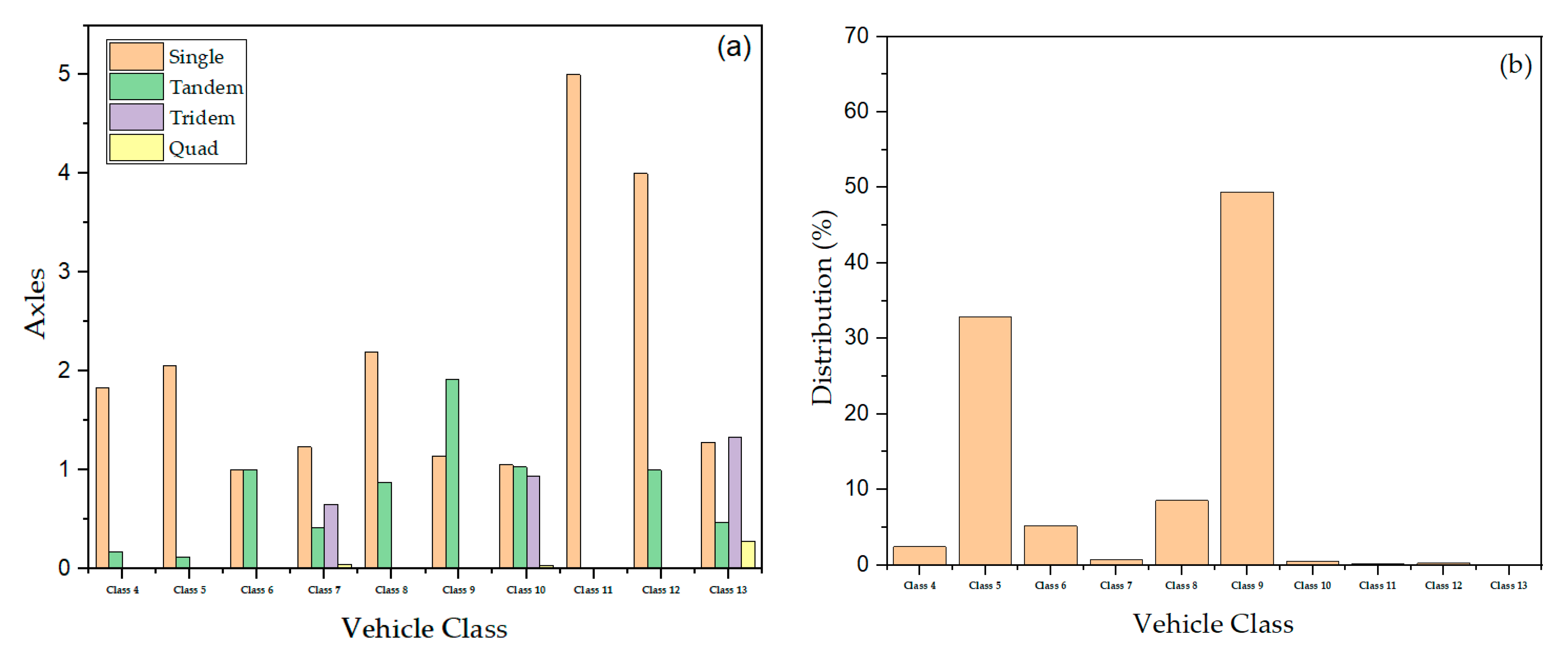
The two-way Average Annual Daily Truck Traffic (AADTT) was calculated using the base year Average Annual Daily Traffic (AADT) and the percentage of trucks annually for the pavement section. There are two lanes in one direction, with an operational speed of 88 km/h and 56 km/h for Laurens/SC-72 and Pickens/SC-72, respectively. The traffic growth rate for each section was assumed to be the same as the historical pavement growth rate (see Table 1). The historical growth rate was determined using AADT measurements from the SCDOT Road Data Services. The vehicle class distribution (FHWA vehicle class 4 through 13), monthly adjustment factors and hourly adjustment factors, axle load configurations (single, tandem, tridem, & quad), and axle per truck values were obtained from the Weigh-in-Motion (WIM) station located at each section. Figure 6 shows an example of axles per truck and vehicle class distribution for the Laurens/SC-72 site. The load values of single axles range from 13 to 182 kN; tandem axles are 27 to 365 kN, and tridem and quad axles are 53 to 454 kN. Default values were used for other traffic inputs (e.g., average axle width, tire pressure, lateral wander, wheelbase, and axle-load configurations) that are not listed in Table 1.
3.5. Climate Inputs
The nearest climate stations, 138396 and 138397, were used for Laurens/SC-72 and Pickens/SC-93, respectively. Table 2 shows the climate data for this analysis. Approximately 3 m (10 ft) depth of water table was used as a default value Level 3 for the PMED software.
3.6. Materials Inputs
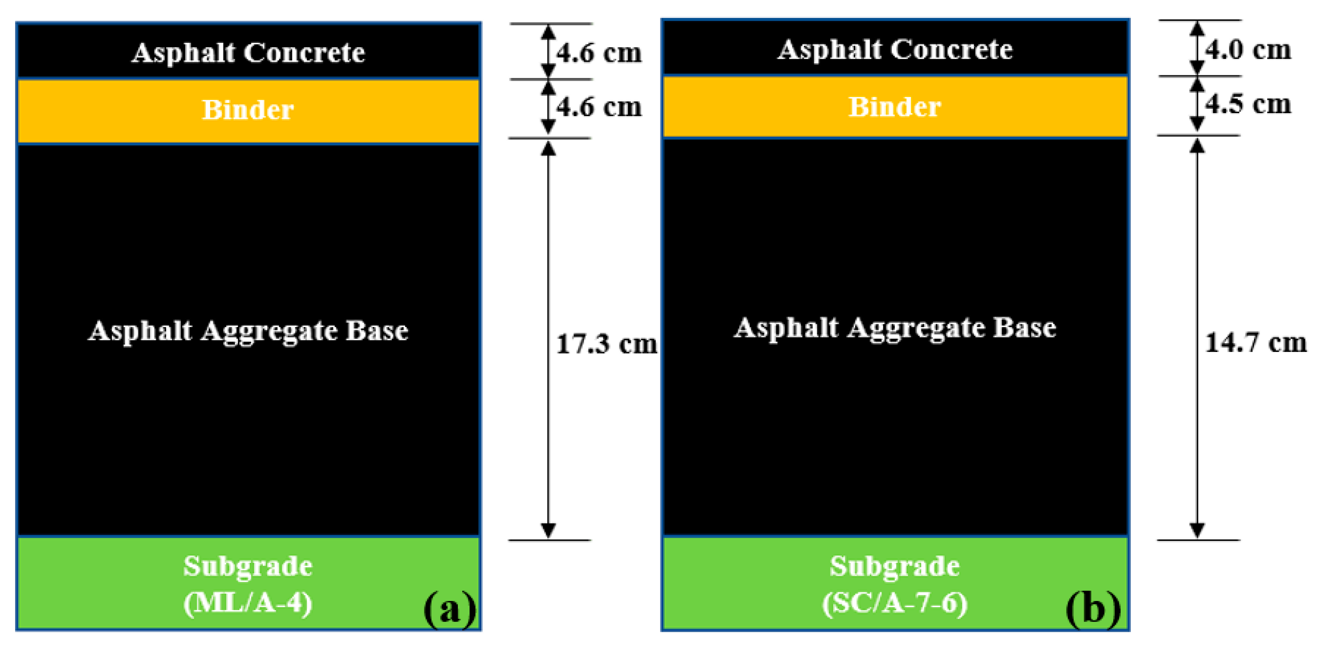
Figure 7 presents the pavement profile for Laurens/SC-93 and Pickens/SC-93. The subgrade input parameters were obtained from laboratory testing (see Table 3) and are classified as Level 1. For unbound subgrade resilient modulus, MR(Lab) and MR(FWD) are Level 2 inputs, whereas MR(default) is a Level 3 input. Each pavement’s average MR value was used to predict distress and IRI. PG 64-22 grade for AC input was selected as a Level 2 input, and dynamic modulus value was used as the default per MEPDG. The remaining AC parameters (see Table 4) were used as Level 3 for each pavement trial.
3.7. Performance Criteria/Distress and Reliability
Table 5 [3] shows the performance criteria and reliability levels for the MEPDG. The performance criteria ensure that a pavement design will perform satisfactorily over its project design life. To estimate the initial IRI for each pavement section, linear regression was performed on the data for each pavement section, as shown in Figure 8. The initial IRI was determined by extrapolating the historical IRI plot of each pavement section to the year of pavement construction completion.
4. Results and Discussion
Results of the soil classification, gradation, pavement predicted distress, and IRI values are discussed, followed by a thickness sensitivity analysis, compared to field measured and the AASHTOWare PMED predicted values.
4.1. Soil Classification and Gradation
Soil classification was conducted according to the USCS (ASTM D 2487) and AASHTO (AASHTO M 145) methods. The #4, #10, #20, #40, #60, #100, and #200 sieves were used to determine the percent finer of the soil from each of the 18 boreholes. Table 6 shows the soil classification and gradation results for 18 samples.
4.2. Pavement Distress
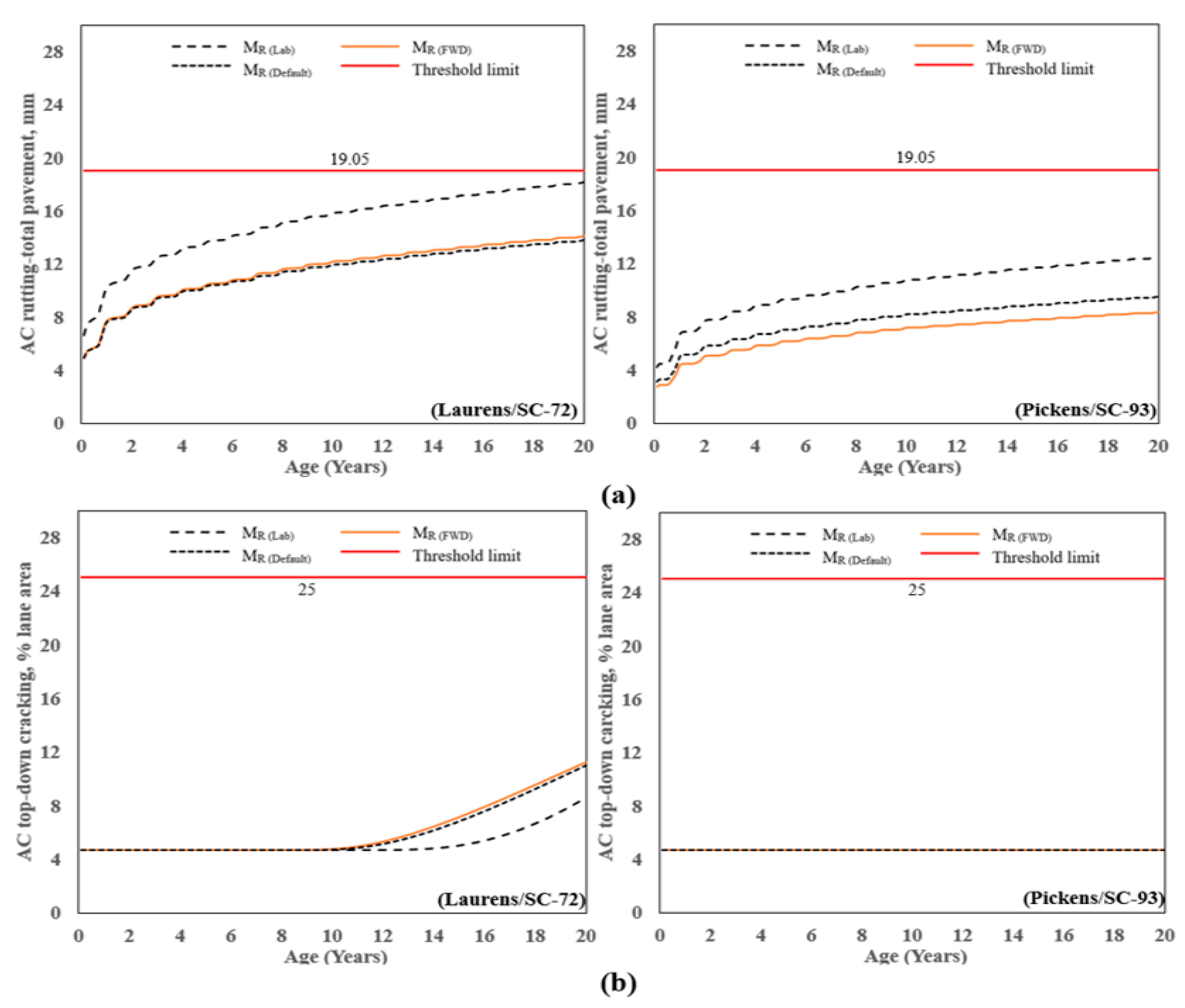
Figure 9a shows the AC total permanent deformation for 20 years. For Laurens/SC-72, the rutting at a period of 20 years ranged from 4.9 mm (found from MR(FWD)) to 18.2 mm (from MR(Lab)), a difference of 115%, and the threshold limit was not met. Similarly, for Pickens/SC-93, the rutting at the age of 20 years ranged from 3.1 mm (found from MR(FWD)) to 12.7 mm (from MR(Lab)), a difference of 120%, and the threshold limit was not met. This shows that using the laboratory-measured value (MR(Lab)) produced the most conservative rutting at 20 years, whereas using the values back-calculated from the FWD data (MR(FWD)) and MR(Default) produced the least conservative result. Similar observations are made for a period of 10 years, which is a typical design life for asphalt pavements in South Carolina, given the historical tendency of flexible pavement to deteriorate after approximately 12 to 15 years, regardless of traffic [24].
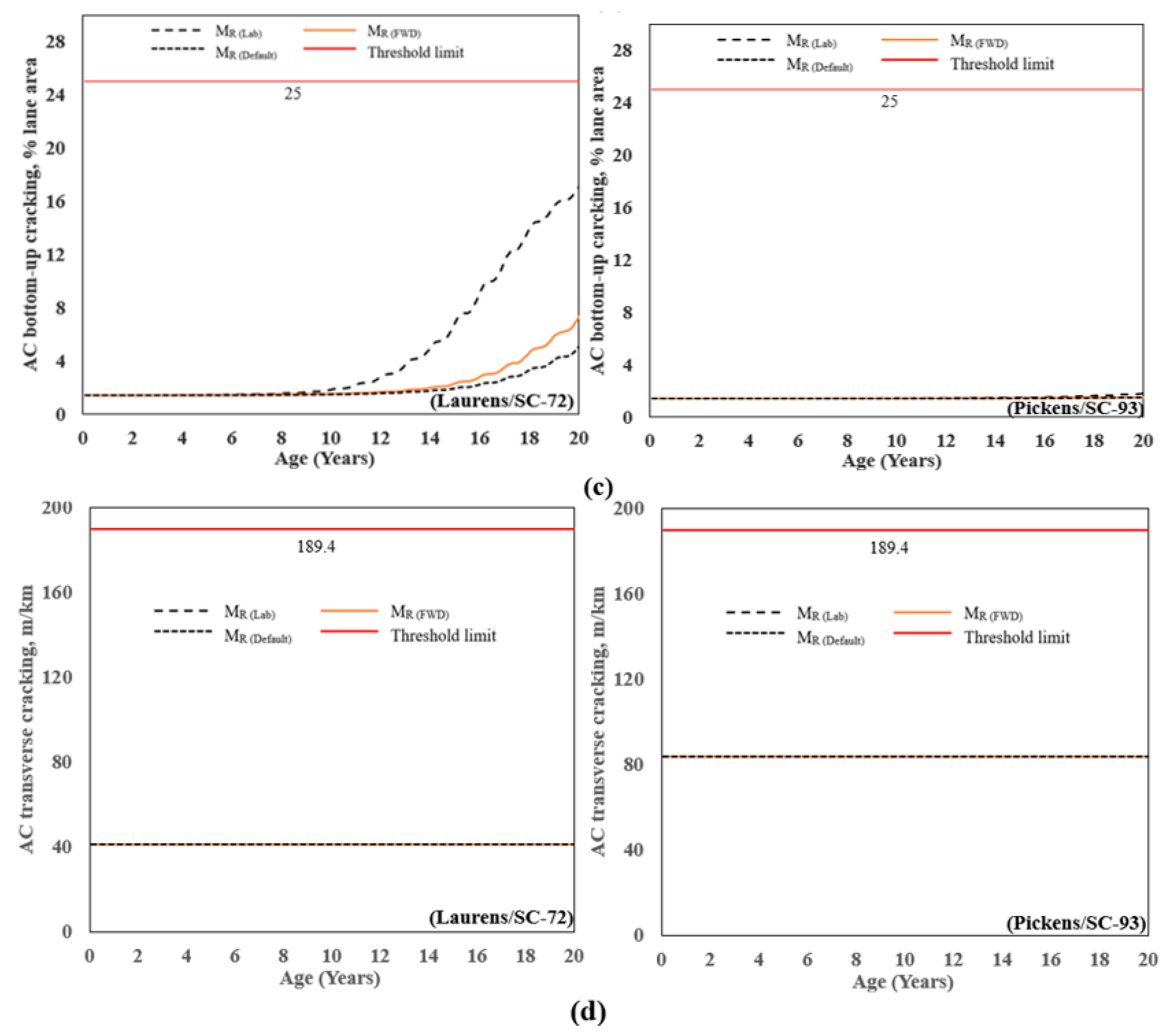
Figure 9b presents the predicted AC top-down cracking for the two pavement sections. The top-down cracking profile for Laurens/SC-72 increased from approximately 4% to 11% after 20 years of age; whereas, for Pickens/SC-72; the profile with age remained constant at 4.6%, which is well below the threshold of 25%. Similarly, the predicted performance for AC bottom-up cracking shown in Figure 9c followed a similar pattern as AC top-down cracking. The maximum and minimum values were observed at 17% and 1.5% for MR(Lab) and MR(Default), respectively, for the Laurens/SC-72, whereas for Pickens/SC-72, the profile with age remained constant at 1.5. For the range of MR studied herein (MR(FWD), MR(Lab), or MR(Default)), the pavements are adequately designed to prevent rutting, top-down cracking, bottom-up cracking, and transverse cracking.
The value of AC transverse/thermal cracking for the Laurens/SC-72 and Pickens/SC-72 is shown in Figure 9d. Both sections follow a similar pattern for thermal cracking, with age for Laurens/SC-72 and Pickens/SC-93 remaining constant at 41 and 84 m/km, respectively.
It is important to note that while the MR of the subgrade soil was the main parameter investigated in this study, other properties of the asphalt layers can significantly influence rutting. For example, increasing the air voids from 4% to 7% has been shown to decrease stiffness and fatigue life by 25% and 69%, respectively [25], and the resilient modulus of warm-mix-asphalt has been shown to be lower than for hot-mix-asphalt [26]. Additionally, changing Poisson’s ratio and resilient modulus for asphalt aggregate base may have a greater effect on pavement deformation [27]. Future work is necessary to study these parameters in the context of the study herein.
4.3. Smoothness/International Roughness Index (IRI)
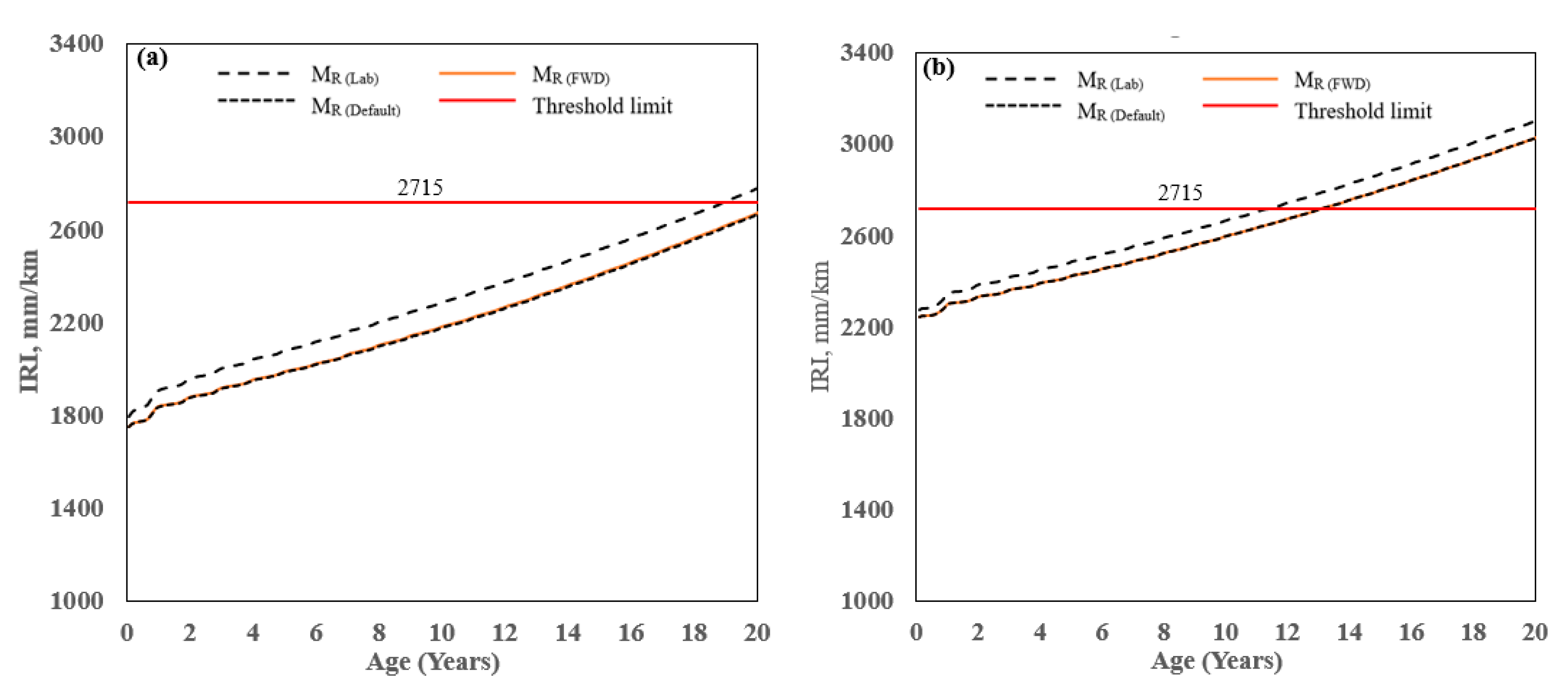
The predicted value of IRI for the two AC pavement sections is shown in Figure 10. For Laurens/SC-72, the IRI at the age of 20 years ranging from 2662 mm/km (found from MR(FWD) & MR(Default)) to 2776 mm/km (from MR(Lab)), a difference of 4.2% and the corresponding pavement ages at which the limiting criterion was met were 20 and 18 years, respectively. Similarly, for Pickens/SC-93, the IRI at the age of 20 years ranged from 3025 mm/km (found from MR(FWD) to 3104 mm/km (from MR(Lab)), a difference of 2.5% and the corresponding pavement ages at which the limiting criterion was met were 13 and 12 years, respectively. The result shows that using the laboratory-measured value (from MR(Lab)) produced the most conservative IRI at 20 years, whereas using the values back-calculated from the FWD data (MR(FWD)) or MR(Default) had the least conservative result. For MR(Default), the threshold limit was met at 20 years for Laurens/SC-72 and 13 years for Pickens/SC-93. Based on the predicted IRI, the difference in the age at which the threshold limit was met was not very sensitive to the MR that was used in the analysis (MR(FWD), MR(Lab), or MR(Default)). Results also show that Pickens/SC-93 predicted higher IRI compared to Laurens/SC-72 because Pickens/93 initial IRI was 1.4 times higher than Laurens/SC-93. So, Initial IRI is most important to predict terminal IRI using PMED software for the cases studied herein.
Overall, IRI is the controlling factor for designing these two flexible pavements. IRI combines thermal cracking, rutting, and fatigue cracking, among other site-specific factors, and the prediction of IRI in PMED is expressed by the following Equation (2) [1,2,3] as:
where IRIo = Initial IRI after construction, m/km, SF = Site factor, FCTotal = Area of fatigue cracking (combined alligator, longitudinal, and reflection cracking in the wheel path), percent of total lane area. TC = Length of transverse cracking (including the reflection of transverse cracks in existing AC pavements), m/km; RD = Average rut depth, mm; C1,2,3,4 = Global calibration factors: C1 = 40.0, C2 = 0.400, C3 = 0.008, and C4 = 0.015.
IRI = IRIo+C1(RD) + C2(FCTotal) + C3(TC) + C4(SF)
As per AASHTO [1,2,3], the laboratory-measured MR(Lab) is considered a hierarchical input Level 2 and is the preferred method to compare predicted results to measured distress values. For MR(Lab), the design threshold value was reached at 18 and 12 years for Laurens/SC-72 and Pickens/SC-93, respectively. Based on the analysis, the section needs to be rehabilitated, or an asphalt thickness layer should be increased to reach the desired pavement service life.
4.4. Thickness Sensitivity Analysis Using Different MR
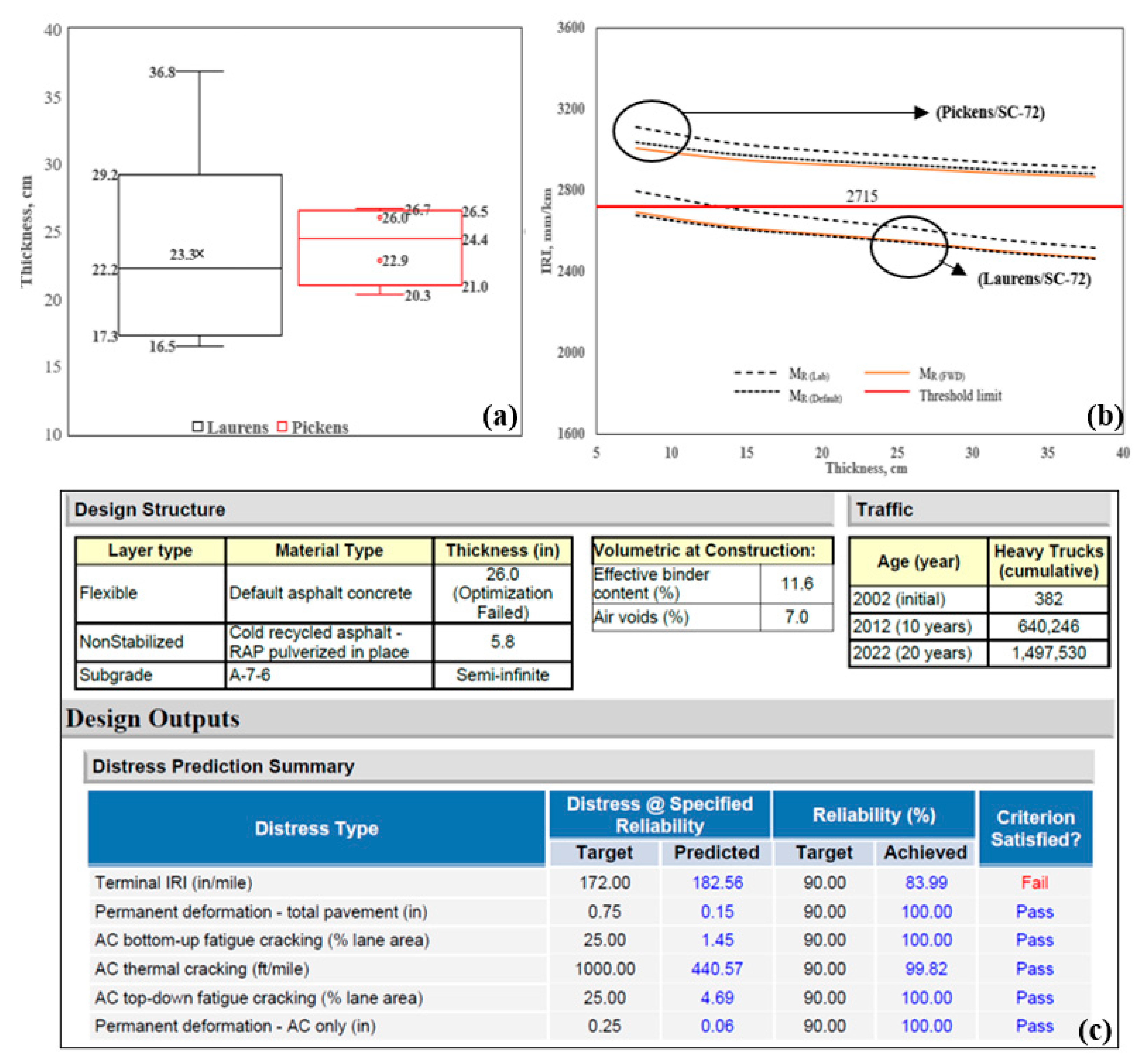
Asphalt cores were obtained in conjunction with manual distress surveys at the two sites. A total of 18 cores were obtained: 13 at Laurens/SC-72 and 5 at Pickens/SC-93, and the thickness of each core was measured. Figure 11a shows the core thickness profiles of Laurens/SC-72 and Pickens/SC-93. For Laurens/SC-72, the core thicknesses ranged from 16.5 cm to 36.8 cm, and the values for Pickens/SC-93 ranged from 20.3 cm to 26.7 cm. For sensitivity analysis, the thickness varied from 8 cm to 38 cm at 5 cm intervals, as shown in Figure 11b. The three different MR were used to estimate the IRI for each thickness. For MR(Lab), the minimum thickness was found to be 13 cm for Laurens/SC-72, whereas a minimum thickness was not achieved for the range of MR studied for Pickens/SC-93. The thickness optimization tool in PMED was used to evaluate layer thickness, and thickness was optimized up to 66 cm (26 in). Results show that the predicted IRI exceeded the threshold limit (2715 mm/km or 172 in/mile), and the criteria were not satisfied for this analysis (see Figure 11c). Note that the measured IRI for Pickens/SC-93 was higher than the Laurens/SC-72 (see Table 4). To improve the results and satisfy the criteria, site-specific values of the material properties should be used instead of the default values, and local calibration factors are needed.
4.5. Comparison between Measured and Predicted Distress
Table 7 shows a comparison between the average and predicted distresses for Laurens/SC-72 and Pickens/SC-93. The measured values of field distress (AC rutting, top-down cracking, bottom-up cracking, and transverse cracking) were collected in 2018 [28], and the IRI values were obtained from the SCDOT Pavement Management System. Table 4 shows that the average predicted rutting is approximately 5 and 10 times higher than the measured value for Laurens/SC-72 and Pickens/SC-72, respectively. The predicted AC top-down cracking is a close agreement (~5.7% difference) with measured value for Laurens/SC-72, whereas 50% lower for Pickens/SC-93. For AC bottom-up cracking, the predicted value is 21% lower than the measured value for Laurens/SC-72 and 27% higher for Pickens/SC-93. Both pavement sections predicted a lower value than the measured value for transverse cracking. The measured value of IRI exceeded the predicted IRI for all of these subgrade MR. Thus, it is concluded that the IRI is over predicted for both sections.
Table 7 also summarizes the residual error/bias (er(mean)) and standard error of estimate (SEE) for both sections. The bias and SEE are low for all distresses except IRI. As stated in Section 4.4, the IRI values heavily depend on the other distresses calculated by the AASHTOWare PMED and site factor. Research is ongoing to eliminate local bias and reduce SEE for developing regional or local calibration factors for predicting pavement distress and IRI, as per AASHTO [29].
5. Summary of Findings and Conclusions
This study investigated the flexible pavement distress and IRI considering the three different subgrade resilient modulus (e.g., MR(Lab), MR(FWD), & MR(Default)) for two sites with fine-grained soils in South Carolina. The results are summarized below:
AC rutting: Results show that the laboratory-measured MR(Lab) predicted higher rutting than FWD and default values. The maximum rutting was observed at 18.2 mm and 12.5 mm at the end of design life for Laurens/SC-72 and Pickens/SC-93, respectively. The predicted rutting was below the design threshold yet exceeded the field-measured distress. Thus, the AASHTOWare PMED over-predicted the AC rutting for the flexible pavement design.
AC top-down and bottom-up cracking: laboratory-measured MR(Lab) predicted the lowest AC top-down cracking for Laurens/SC-72 compared to MR(FWD) and MR(Default), whereas cracking remained constant with pavement age for all three MR values for Pickens/SC-93. For MR(Lab), the PMED predicted 1.4 times higher bottom-up cracking than the field-measured value for Laurens/SC-72. Pickens/SC-93 predicted value was 1.4%, whereas the field measured value was 1.1%.
Transverse cracking: The predicted transverse cracking was 41% and 84% for Laurens/SC-72 and Pickens/SC-93, respectively. The PMED predicted 75% and 18% lower values than measured transverse cracking for Laurens/SC-72 and Pickens/SC-93, respectively.
Smoothness/IRI: Results show that the higher resilient modulus (MR(FWD)) predicted lower IRI and higher pavement service life. The maximum bias and SEE were observed at the IRI prediction, so extensive research is needed to eliminate bias and reduce SEE to determine local calibration factors per AASHTO [29] in South Carolina.
This study also investigated the effect of asphalt thickness on pavement performance. The observations are summarized as follows:
AC rutting: For a range of AC thickness from 8 cm to 38 cm at a 5 cm interval, the PMED analysis for AC rutting showed a reduction of 57% and 62% with increasing asphalt thickness for Laurens/SC-72 and Pickens/SC-93, respectively.
AC bottom-up cracking: For Laurens/SC-72, at an initial thickness of 8 cm, the AC bottom-up cracking was observed around 15%. With increasing AC thickness, the cracking value was significantly reduced and recorded at approximately 1.4% for a thickness of 38 cm. On the contrary, AC bottom-up cracking did not change with increasing AC thickness for Pickens/SC-93. The cracking value was 1.5% for all thicknesses studied.
AC top-down and transverse cracking: For the range of AC thicknesses studied, the predicted top-down cracking and transverse cracking did not change with AC thickness. Top-down cracking was approximately 4% for all thicknesses for both sites, whereas transverse cracking was 41% and 84% for all thicknesses studied for Laurens/SC-72 and Pickens/SC-93, respectively.
Smoothness/IRI: Using MR(Lab), the predicted IRI decreased by 11% and 6% for Laurens/SC-72 and Pickens/SC-93, respectively, for thicknesses from 8 cm to 38 cm.
The findings in this study can help one understand the effects of subgrade resilient modulus variables on distress predictions and IRI and are also beneficial in creating a MR catalog.
Author Contributions
Conceptualization, Methodology, Software, Validation, Writing—Original draft, Writing—review and editing, K.M.I.; Conceptualization, Methodology, Writing—review and editing, S.L.G. All authors have read and agreed to the published version of the manuscript.
Funding
This project was funded by the SCDOT and the FHWA under grant SPR 732. Any opinions, findings, conclusions, or recommendations expressed in this material are those of the authors and do not necessarily reflect the views of the SCDOT or the FHWA.
Institutional Review Board Statement
The authors claim that there are no ethical issues involved in this research.
Informed Consent Statement
All of the authors consented to participate in this research and contributed to the research. All of the authors consent to publication of the research.
Data Availability Statement
Not applicable.
Acknowledgments
The authors would like to acknowledge the SCDOT for their assistance in collecting the FWD data and Bradley Putman of Clemson University for facilitating the subgrade soil sampling efforts. Mostaqur is acknowledged for his help with the sample collection, laboratory testing, and laboratory results. The authors also would like to acknowledge Nicolet Devine for analyzing the IRI and traffic growth rate data and Clifton Dale Hurley for collecting the measured distress data.
Conflicts of Interest
The authors declare no conflict of interest.
References
- AASHTO. Mechanistic Empirical Pavement Design Guide: A Manual Practice, Interim ed.; AASHTO: Washington, DC, USA, 2008. [Google Scholar]
- AASHTO. Mechanistic-Empirical Pavement Design Guide: A Manual of Practice, 2nd ed.; AASHTO: Washington, DC, USA, 2015. [Google Scholar]
- AASHTO. Mechanistic-Empirical Pavement Design Guide: A Manual of Practice, 3rd ed.; AASHTO: Washington, DC, USA, 2020. [Google Scholar]
- Baus, R.L.; Stires, N.R. Mechanistic-Empirical Pavement Design Guide Implementation. FHWA-SC-10-01. Transp. Res. Rec. 2010, 29208, 1–104. [Google Scholar]
- Yang, X.; You, Z.; Hiller, J.; Watkins, D.J. Correlation Analysis between Temperature Indices and Flexible Pavement Distress Predictions Using ME Design. J.Cold Reg. Eng. 2017, 31, 04017009. [Google Scholar] [CrossRef]
- Rahman, M.M.; Gassman, S.L. Effect of resilient modulus of undisturbed subgrade soils on pavement rutting. Int. JGE 2019, 13, 152–161. [Google Scholar] [CrossRef]
- Zarei, S.; Alae, M.; Ouyang, J.; Zhao, Y. Rutting and surface-initiated cracking mechanisms of semi-flexible pavements with cement asphalt emulsion pastes. IJPE 2022, 1–15. [Google Scholar] [CrossRef]
- Zaghloul, S.; Ayed, A.A.; Abd El Halim, A.; Vitillo, N.; Sauber, R. Investigations of environmental and traffic impacts on me pavement design guide predictions. TRR 2006, 1967, 148–159. [Google Scholar]
- Jannat, G.; Yuan, X.X.; Shehata, M. Development of Regression Equations For Local Calibration of Rutting and IRI as Predicted by the MEPDG Models for Flexible Pavements Using Ontario’s Long-Term PMS data. IJPE 2016, 17, 166–175. [Google Scholar]
- Jadoun, F.; Kim, Y. Calibrating mechanistic–empirical pavement design guide for North Carolina: Genetic algorithm and generalized reduced gradient optimization methods. Transp. Res. Rec. 2012, 2305, 131–140. [Google Scholar] [CrossRef]
- Singh, D.; Zaman, M.; Commuri, S. Evaluation of measured and estimated dynamic moduli for selected asphalt mixes. J. ASTM Int. 2011, 8, 1–19. [Google Scholar] [CrossRef]
- Saxena, P.; Tompkins, D.; Khazanovich, L.; Balbo, J.T. Evaluation of characterization and performance modeling of cementitiously stabilized layers in the Mechanistic-Empirical pavement design guide. Transp. Res. Rec. 2010, 2186, 111–119. [Google Scholar] [CrossRef]
- Ng, C.W.W.; Zhou, C.; Yuan, Q.; Xu, J. Resilient modulus of unsaturated subgrade soil: Experimental and theoretical investigations. Can. Geotechn. J. 2013, 50, 223–232. [Google Scholar] [CrossRef]
- Gassman, S.L.; Rahman, M.M. Calibration of the Aashto Pavement Design Guide to South Carolina Conditions—Phase I; No. FHWA-SC-16-02; South Carolina Dept. of Transportation: Columbia, SC, USA, 2016; p. 159.
- Johanneck, L.; Khazanovich, L. Comprehensive Evaluation of Effect of Climate in Mechanistic-Empirical Pavement Design Guide predictions. TRR 2010, 2170, 45–55. [Google Scholar]
- Zapata, C.E.; Andrei, D.; Witzack, M.W. Incorporation of environmental effects in pavement design. Road Mater. Pavement Des. 2007, 8, 667–693. [Google Scholar] [CrossRef]
- Orobio, A.; Zaniewski, J. Sampling-based sensitivity analysis of the mechanistic-empirical pavement design guide applied to material inputs. TRR 2011, 2226, 85–93. [Google Scholar] [CrossRef]
- Islam, K.M.; Gassman, S.L. Influence of subgrade resilient modulus selection methodology on AASHTOWare pavement ME design. In Proceedings of the Geo-Congress 2022, Charlotte, NC, USA, 20–23 March 2022; pp. 192–204. [Google Scholar]
- Puppala, A.J.; Saride, S.; Chomtid, S.J. Experimental and Modeling Studies of Permanent Strains of Subgrade Soils. J. Geotechn. Geoenviron. Eng. 2009, 135, 1379–1389. [Google Scholar] [CrossRef]
- AASHTO. User Manual for Pavement ME Deflection Data Analysis and Backcalcul Tool. 2021. Available online: https://me-design.com/MEDesign/data/BcT_UserManual.pdf (accessed on 3 April 2022).
- AASHTO-T307-99; Standard Method of Test for Determining the Resilient Modulus of Soils and Aggregate Materials Standard Method of Test for Soils and Aggregate Materials. AASHTO: Washington, DC, USA, 2017.
- Dynatest Consulting, Inc. Dynatest FWD/HWD Test Systems. Dynatest Consulting, Inc.: Stark, FL, USA, 2009. Available online: http://www.dynatest.com/media/4180/3_dynatest_fwd_hwd.pdf (accessed on 3 April 2022).
- Islam, K.M.; Gassman, S.; Rahman, M.M. Field and laboratory characterization of subgrade resilient modulus for pavement mechanistic-empirical pavement design guide application. Transp. Res. Rec. 2020, 2674, 921–930. [Google Scholar] [CrossRef]
- Pavement Design Guidelines; South Carolina Department of Transportation, Office of Materials and Research Pavement Design Unit: Columbia, SC, USA, 2008.
- Fattah, M.Y.; Al Helo, K.H.I.; Qasim, Z.I. Prediction models for fatigue resistance of local hot mix asphalt. Road Mater. Pavement Des. 2016, 17, 793–809. [Google Scholar] [CrossRef]
- Hilal, M.M.; Fattah, M.Y. Evaluation of resilient modulus and rutting for warm asphalt mixtures: A local study in Iraq. Appl. Sci. 2022, 12, 12841. [Google Scholar] [CrossRef]
- Sun, J.; Huang, Y. Modeling the simultaneous effects of particle size and porosity in simulating geo-materials. Materials 2022, 15, 1576. [Google Scholar] [CrossRef] [PubMed]
- Hurley, C.D. Asphalt Pavement Evaluation to Support the Calibration of the AASHTO MEPDG for South Carolina Conditions. Master’s Thesis, Clemson University, Clemson, SC, USA, 2019. [Google Scholar]
- AASHTO. Guided for the Local Calibration of the ME Pavement Design Guide; Publication code: LCG-1; AASHTO: Washington, DC, USA, 2010; ISBN 978-1-56051-449-7. [Google Scholar]
Figure 1.
(a) Pavement location map and coring Location map for (b) Laurens/SC-72 (https://www.google.com/maps/d/u/0/edit?mid=1jj-00vFohfGFblAqnFJDa3s54mlurHyc&ll=34.39052226622161%2C-81.85667629577638&z=13, accessed on 3 April 2022) and (c) Pickens/SC-93 (https://www.google.com/maps/d/u/0/edit?mid=16fAsTCLDfDB_4usuSCCZHGEIdSW-Z4Cy&ll=34.680649589059044%2C-82.83778701651015&z=15, accessed on 3 April 2022).

Figure 2.
Subgrade sample collection process: (a) Shelby tube sample collected with assistance from A Jeep Jack, (b) Bulk sample collected by hand auger, and (c) Bulk samples.
Figure 2.
Subgrade sample collection process: (a) Shelby tube sample collected with assistance from A Jeep Jack, (b) Bulk sample collected by hand auger, and (c) Bulk samples.

Figure 3.
Flow chart of the study.

Figure 4.
FWD:(a) Loading frame, and (b) system.

Figure 5.
Logarithmic function of Equation (1).

Figure 6.
Example of (a) axle per truck and (b) vehicle class distribution for Laurens/SC-72.

Figure 7.
Pavement profile: (a) Laurens/SC-72, and (b) Pickens/SC-93 (figures are not drawn to scale).
Figure 7.
Pavement profile: (a) Laurens/SC-72, and (b) Pickens/SC-93 (figures are not drawn to scale).

Figure 8.
Initial IRI estimation for Laurens/SC-72 and Pickens/SC-93.

Figure 9.
Predicted distress vs. time: (a) AC rutting, (b) AC top-down cracking, (c) AC bottom-up cracking, and (d) AC transverse/thermal cracking.
Figure 9.
Predicted distress vs. time: (a) AC rutting, (b) AC top-down cracking, (c) AC bottom-up cracking, and (d) AC transverse/thermal cracking.


Figure 10.
Predicted IRI: (a) Laurens/SC-72, and (b) Pickens/SC-93.

Figure 11.
Results for Laurens/SC-72 and Pickens/SC-93: (a) Asphalt core thickness profile, (b) Sensitivity analysis for predicting IRI, and (c) Thickness optimization result for Pickens/SC-93 (picture directly taken from AASHTOWare PMED output).
Figure 11.
Results for Laurens/SC-72 and Pickens/SC-93: (a) Asphalt core thickness profile, (b) Sensitivity analysis for predicting IRI, and (c) Thickness optimization result for Pickens/SC-93 (picture directly taken from AASHTOWare PMED output).


Table 1.
Traffic inputs for the flexible pavement design.
| Input Parameters | Traffic Level | |
|---|---|---|
| Laurens/SC-72 | Pickens/SC-93 | |
| Initial two-way AADTT | 834 | 382 |
| Number of lanes | 2 | 2 |
| Growth rate (%) | 2.04 | 0.87 |
| Percent truck in design direction | 50.3 | 51.7 |
| Percent truck in design lane | 84.1 | 75.0 |
| Operational speed (km/h) | 88 | 56 |
Table 2.
Summary of climate data.
| Input Parameter | Laurens/SC-72 | Pickens/SC-93 |
|---|---|---|
| Mean annual air temperature (deg F) | 55.9 | 57.8 |
| Mean annual precipitation (in) | 65.8 | 58 |
| Freezing index (deg F days) | 104.9 | 70.8 |
| Average annual number of freeze/thaw cycles | 70.4 | 63 |
| Number of wet days | 294.4 | 289.7 |
Table 3.
Summary of material inputs for AASHTOWare PMED (v2.6.1).
| County/Region | Laurens/SC-72 | Pickens/SC-93 | ||
|---|---|---|---|---|
| Base Year | 2002 | 2001 | ||
| Design Life (years) | 20 | |||
| Asphalt Binder ** | PG 64-22 | |||
| Effective Binder Content (%) *** | 11.6 | |||
| Unit Weight (kN/m3) *** | 23.5 | |||
| Air Void (%) *** | 7 | |||
| Dynamic Modulus (MPa) *** | Input level 3 | |||
| Subgrade properties | ||||
| Avg. Subgrade Modulus (MPa) | Lab | MR(Lab) ** | 54 | 45 |
| FWD | MR(FWD) ** | 109 | 137 | |
| Default | MR(Default) *** | 103 | 90 | |
| USCS/AASHTO | ML/A-4 | SC/A-7-6 | ||
| Liquid Limit & Plasticity Index * | 48 & 20 | 42 & 14 | ||
| %F | 47.0 | 44.0 | ||
| Maximum Dry Unit Weight, γdmax (kN/m3) * | 17.0 | 18.5 | ||
| Water Content (%) & Specific Gravity * | 18 & 2.74 | 13.8 & 2.71 | ||
Note: * = Level 1 input, ** = Level 2 input, *** = Level 3 input, NP = non-plastic, F = %passing #200 sieve, average MR for each site found from repeated load triaxial tests per [21] on tube samples at in situ water content and density [23]. Average back-calculated MR for each site found from FWD tests using AASHTOWare back-calculation tool (v 1.1.2) [20], default value taken from the PMED software (v2.6.1), soil classification as per ASTM D2488 and AASHTO M145.
Table 4.
Summary of material inputs for asphalt aggregate base.
| Parameters | Input Values | Remarks |
|---|---|---|
| Poison’s ratio | 0.35 | Default values per MEPDG 2020 [3] |
| Coefficient of lateral earth pressure | 0.5 | |
| Resilient Modulus, MPa | 138 | |
| Gradation | ||
| Sieve Size | Percent Passing | |
| #200 | 8.7 | |
| #80 | 12.9 | |
| #40 | 20 | |
| #10 | 33.8 | |
| #4 | 44.7 | |
Table 5.
Performance criteria and reliability summary for flexible pavement trial design.
| Distress Type | Threshold Value at the End of Design Life & Reliability (%) |
|---|---|
| Initial IRI, mm/km | Laurens/SC-72: 1182.7 & Pickens/SC-93: 1614.4 |
| Terminal IRI, mm/km | 2715 & 90 |
| AC top-down fatigue cracking, % lane area | 25 & 90 |
| AC bottom-up fatigue cracking, % lane area | 25 & 90 |
| AC transverse (thermal) cracking, m/km | 189.4 & 90 |
| AC rutting/Permanent deformation–total pavement, mm | 19.05 & 90 |
Table 6.
Soil classification and gradation for 18 samples.
| Site | BH | Gradation Size 1 | USCS/AASHTO 2 | ||||||
|---|---|---|---|---|---|---|---|---|---|
| #4 | #10 | #20 | #40 | #60 | #100 | #200 | |||
| Laurens /SC-72 | 1 | 99.2 | 97.1 | 91.0 | 80.2 | 75.0 | 51.0 | 47.0 | ML/A-4 |
| 2 | 95.2 | 93.8 | 90.0 | 72.0 | 66.5 | 52.0 | 52.0 | ML/A-4 | |
| 3 | 99.0 | 97.0 | 91.0 | 82.0 | 73.0 | 52.0 | 47.0 | ML/A-4 | |
| 4 | 98.1 | 94.2 | 90.2 | 85.1 | 70.2 | 62.0 | 54.0 | ML/A-4 | |
| 5 | 97.2 | 93.5 | 92.0 | 75.2 | 70.1 | 48.5 | 55.0 | ML/A-4 | |
| 6 | 93.0 | 88.0 | 80.0 | 71.0 | 62.0 | 54.0 | 45.0 | ML/A-4 | |
| 7 | 99.0 | 96.2 | 91.1 | 79.5 | 72.4 | 50.6 | 45.0 | ML/A-4 | |
| 8 | 99.1 | 97.3 | 90.5 | 75.2 | 62.1 | 51.3 | 52.0 | ML/A-4 | |
| 9 | 95.0 | 94.0 | 89.0 | 77.0 | 67.0 | 56.0 | 48.0 | ML/A-4 | |
| 10 | 93.0 | 88.0 | 80.0 | 71.0 | 62.0 | 54.0 | 51.0 | ML/A-4 | |
| 11 | 97.0 | 95.0 | 92.0 | 84.0 | 76.0 | 66.3 | 48.0 | ML/A-4 | |
| 12 | 99.0 | 97.0 | 91.0 | 82.0 | 73.0 | 52.0 | 46.0 | ML/A-4 | |
| 13 | 98.0 | 94.2 | 90.2 | 85.1 | 70.2 | 62.0 | 40.0 | ML/A-4 | |
| Pickens /SC-93 | 1 | 93.2 | 88.0 | 80.0 | 71.0 | 62.0 | 54.0 | 44.6 | SC/A-7-6 |
| 2 | 99.3 | 96.2 | 91.1 | 79.5 | 72.4 | 50.6 | 43.8 | SM/A-7-6 | |
| 3 | 99.2 | 97.1 | 91.0 | 80.2 | 75.0 | 51.0 | 43.4 | SC/A-7-6 | |
| 4 | 93.1 | 88.0 | 80.0 | 71.0 | 62.0 | 54.0 | 51.2 | ML/A-4 | |
| 5 | 98.1 | 96.2 | 91.1 | 79.5 | 72.4 | 50.6 | 44.0 | SC/A-7-6 | |
1 %passing #sieve, 2 soil classification as per ASTM D2488 and AASHTO M145.
Table 7.
Summary of measured and predicted distress values.
| Distress & IRI | Laurens/SC-72 | Pickens/SC-93 | ||||||||||||
|---|---|---|---|---|---|---|---|---|---|---|---|---|---|---|
| Distress | er(mean) | SEE | Distress | er(mean) | SEE | |||||||||
| yi | xi | yi | xi | |||||||||||
| 1 | 2 | 3 | Avg. | 1 | 2 | 3 | Avg. | |||||||
| Rutting (mm) | 3.0 | 18.2 | 14.1 | 13.8 | 15.4 | 12.3 | 2.4 | 1.0 | 12.5 | 8.3 | 8.5 | 9.8 | 8.8 | 2.3 |
| Top-down (% lane area) | 10.9 | 8.5 | 11.2 | 11.1 | 10.3 | −0.6 | 1.8 | 8.8 | 4.7 | 4.7 | 4.7 | 4.7 | −4.1 | 0 |
| Bottom-up (% lane area) | 11.9 | 17.1 | 7.3 | 5.1 | 9.8 | −2.1 | 2.4 | 1.1 | 1.4 | 1.4 | 1.4 | 1.4 | 0.3 | 0.2 |
| Transvers (m/km) | 166 | 41 | 41 | 41 | 41 | −126 | 0 | 102 | 84 | 84 | 84 | 84 | −19 | 0 |
| IRI (mm/km) | 1515 | 2604 | 2541 | 2525 | 2557 | 1042 | 11 | 2241 | 2983 | 2920 | 2936 | 2770 | 529 | 9.2 |
Note: yi = measured value; xi = predicted value; 1, 2, & 3 = predicted value taken from using MR(Lab); MR(FWD); & MR(Default), respectively; er (mean) = residual error/bias = xi − yi; SEE = standard error of estimate = , n = no. of observations.
Disclaimer/Publisher’s Note: The statements, opinions and data contained in all publications are solely those of the individual author(s) and contributor(s) and not of MDPI and/or the editor(s). MDPI and/or the editor(s) disclaim responsibility for any injury to people or property resulting from any ideas, methods, instructions or products referred to in the content. |
© 2023 by the authors. Licensee MDPI, Basel, Switzerland. This article is an open access article distributed under the terms and conditions of the Creative Commons Attribution (CC BY) license (https://creativecommons.org/licenses/by/4.0/).
Share and Cite
MDPI and ACS Style
Islam, K.M.; Gassman, S.L. Predicting Flexible Pavement Distress and IRI Considering Subgrade Resilient Modulus of Fine-Grained Soils Using MEPDG. Materials 2023, 16, 1126. https://doi.org/10.3390/ma16031126
AMA Style
Islam KM, Gassman SL. Predicting Flexible Pavement Distress and IRI Considering Subgrade Resilient Modulus of Fine-Grained Soils Using MEPDG. Materials. 2023; 16(3):1126. https://doi.org/10.3390/ma16031126
Chicago/Turabian StyleIslam, Kazi Moinul, and Sarah L. Gassman. 2023. "Predicting Flexible Pavement Distress and IRI Considering Subgrade Resilient Modulus of Fine-Grained Soils Using MEPDG" Materials 16, no. 3: 1126. https://doi.org/10.3390/ma16031126
Note that from the first issue of 2016, this journal uses article numbers instead of page numbers. See further details here.