
Plate Load Tests of Soft Foundations Reinforced by Soilbags with Solid Wastes for Wind Farms
Abstract
:1. Introduction
2. Materials and Methods
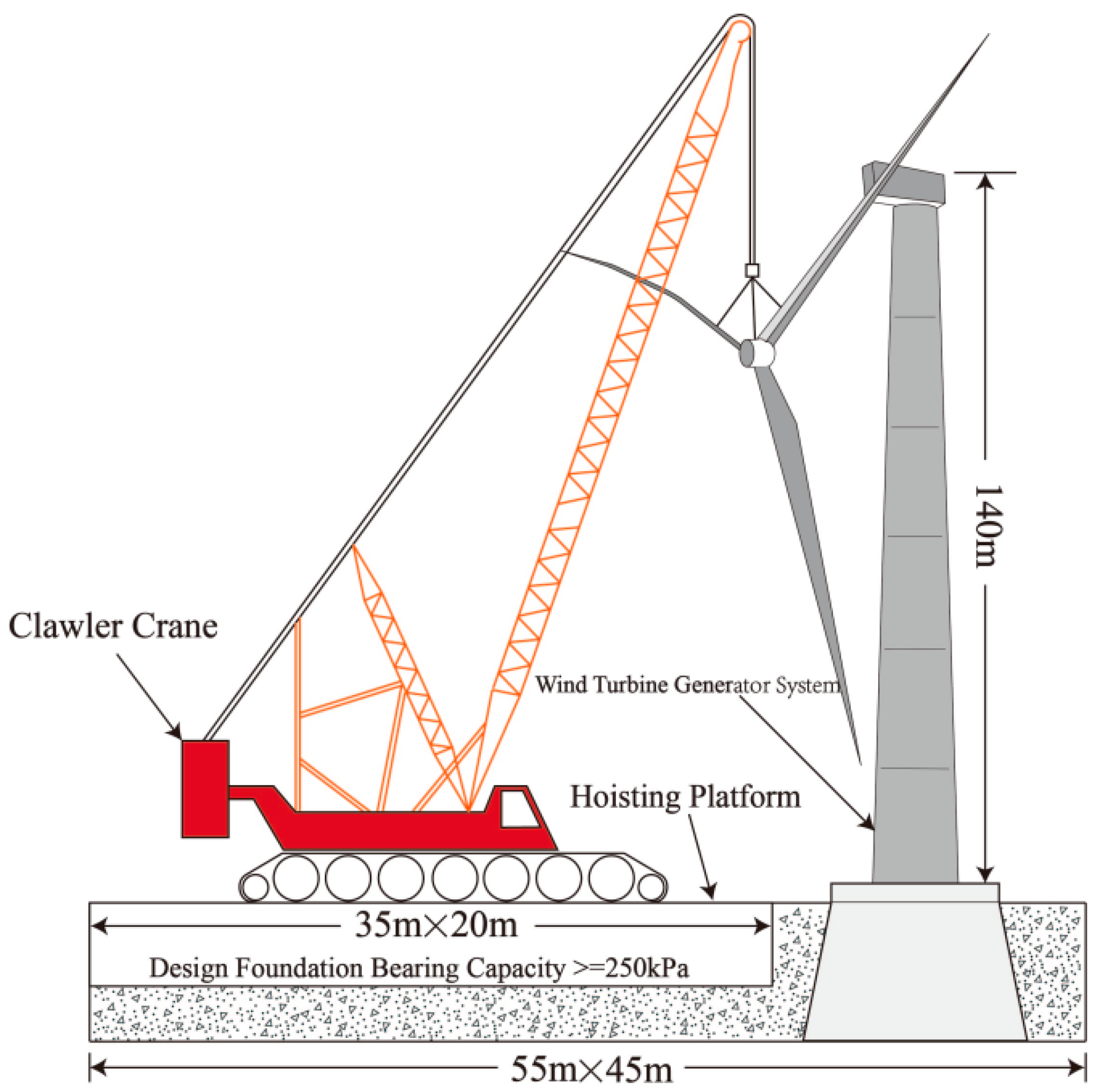
2.1. Project Background
2.2. Technical Principle of Soilbags
2.3. Field Tests of Soilbag-Reinforced Foundations
2.3.1. Test Site Conditions
2.3.2. Soilbag Design
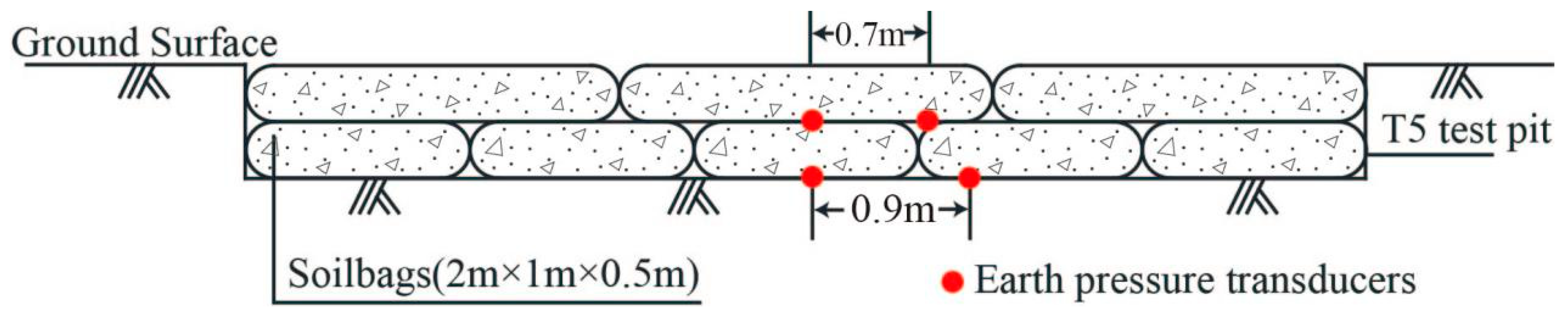
2.3.3. Soilbag Layout
- T5 test site
- 2.
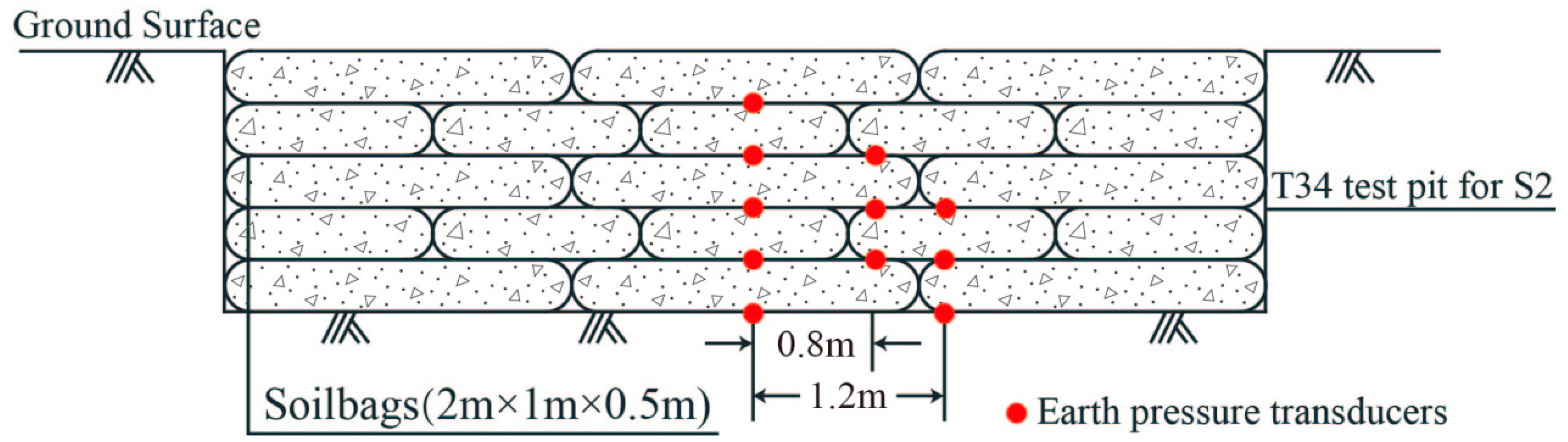
- T34 test site
- Scheme S2: 5 layers of staggered soilbags (n = 5)
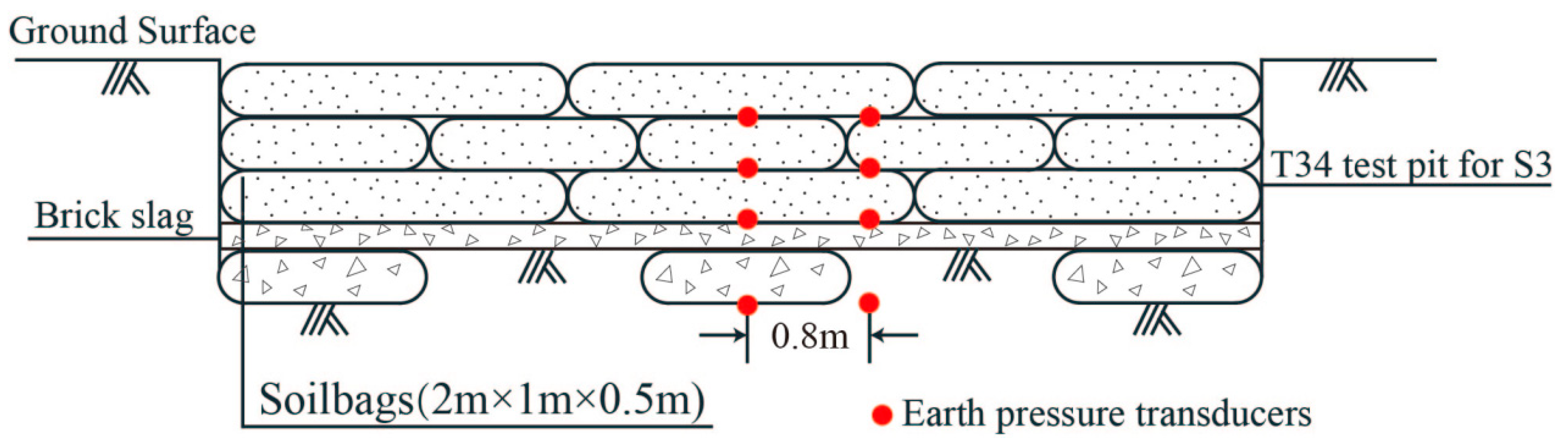
- Scheme S3: 3 layers of staggered soilbags (n = 3) + bottom sludge treatment
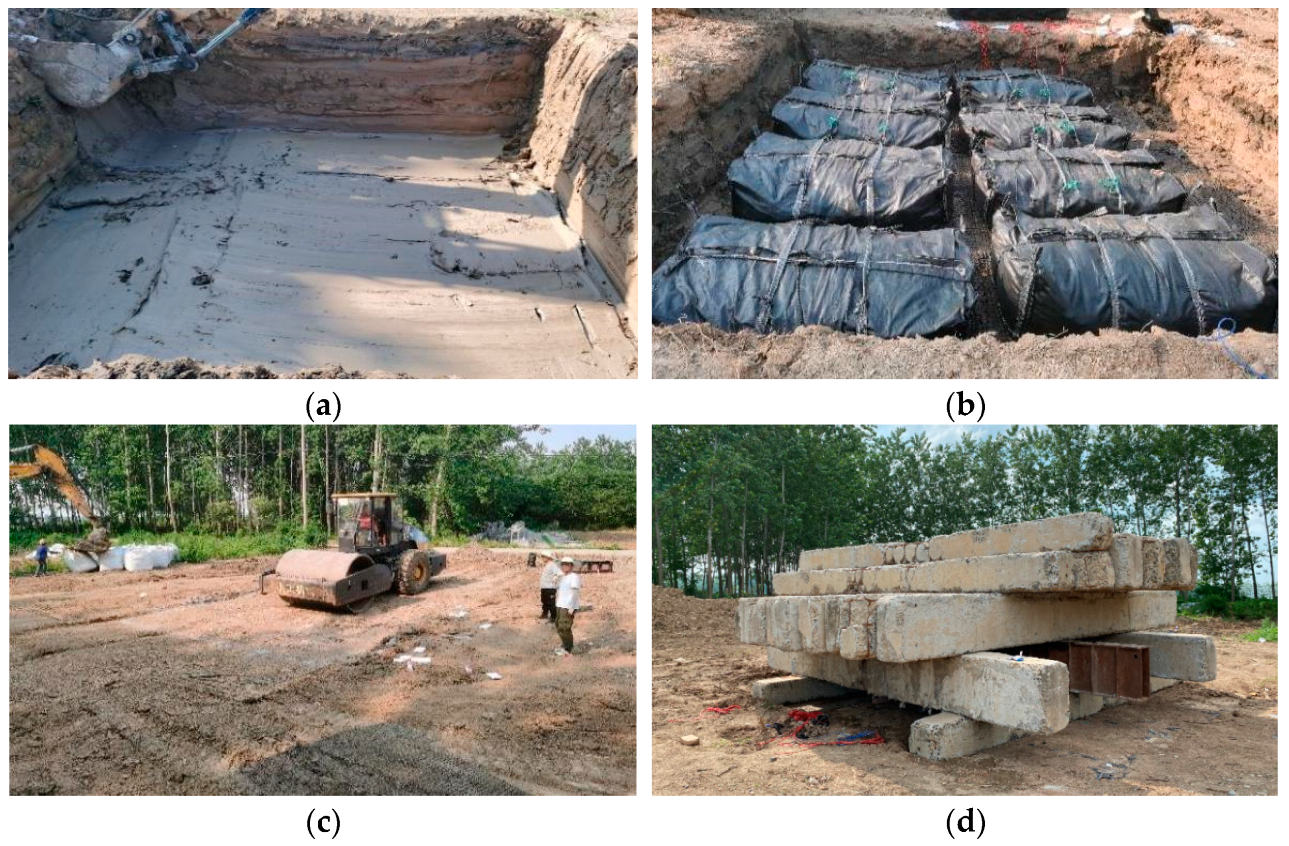
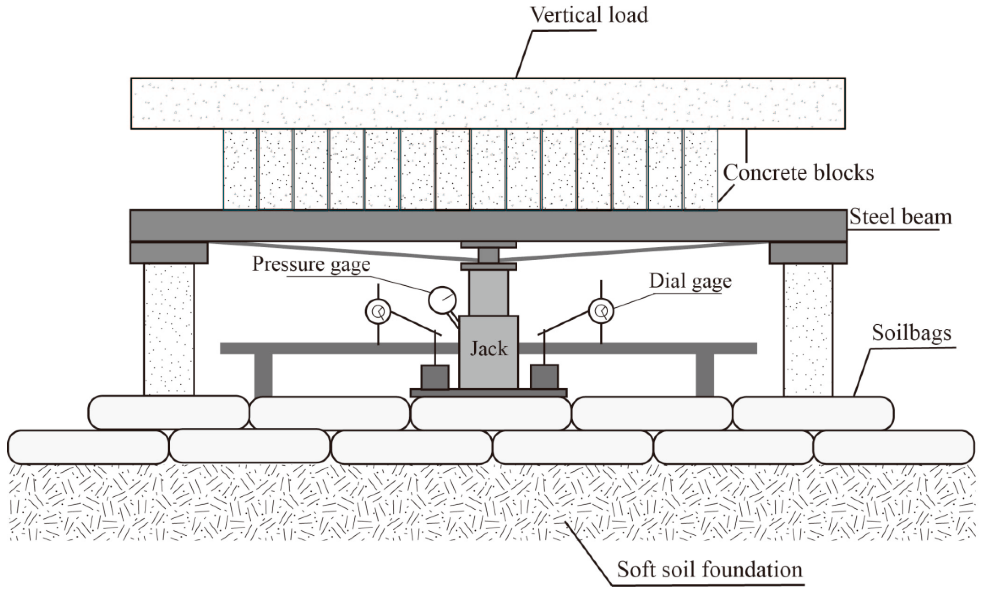
2.3.4. Field Test Overview
3. Results and Analysis
3.1. p-s Curve
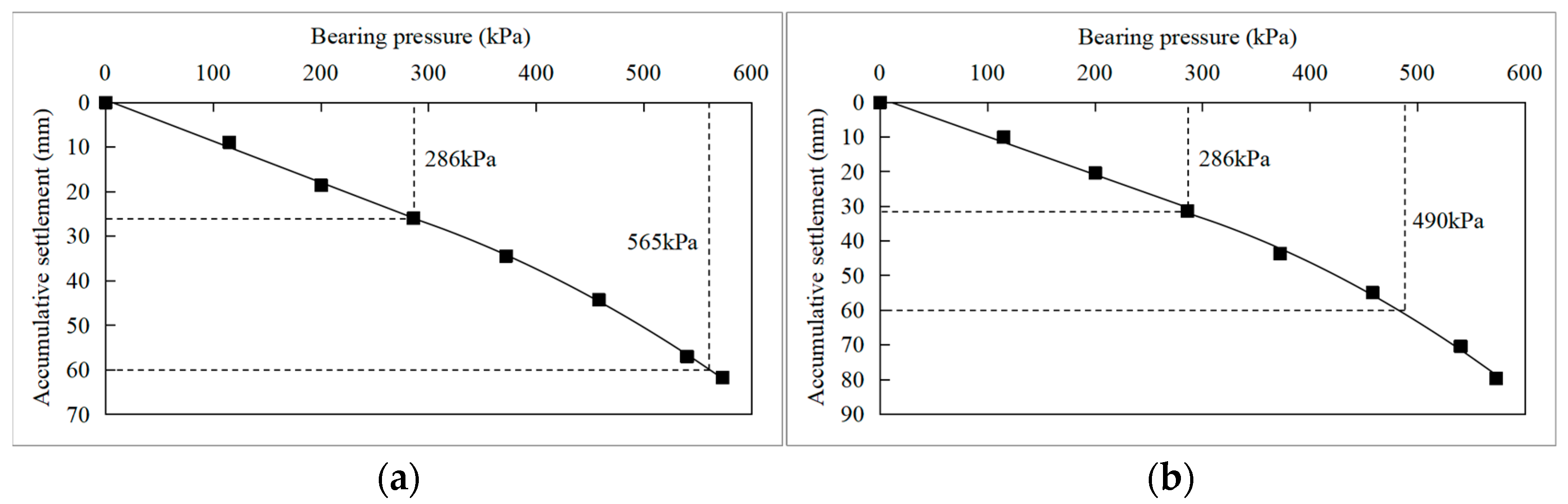
3.1.1. S1
- (1)
- The compressibility of soilbags filled with pure plain soil was greater, so the soilbag compression deformation of S1b was greater under the same external loads, which increased the footing settlement during plate load tests.
- (2)
- After construction compaction, the thickness of the soilbag filled with plain soil was about 0.3–0.35 m, which was slightly less than that of the soilbag containing plain soil mixed with brick slag, which was 0.35–0.4 m. Thus, the total thickness of the reinforcement layer of S1b was slightly less than that of S1a; in this way, the additional stress transmitted to the soft soil under the soilbag reinforcement layer was greater. Therefore, the reinforcement effect of soilbags infilled with plain soil mixed with brick slag was better than with pure plain soil.
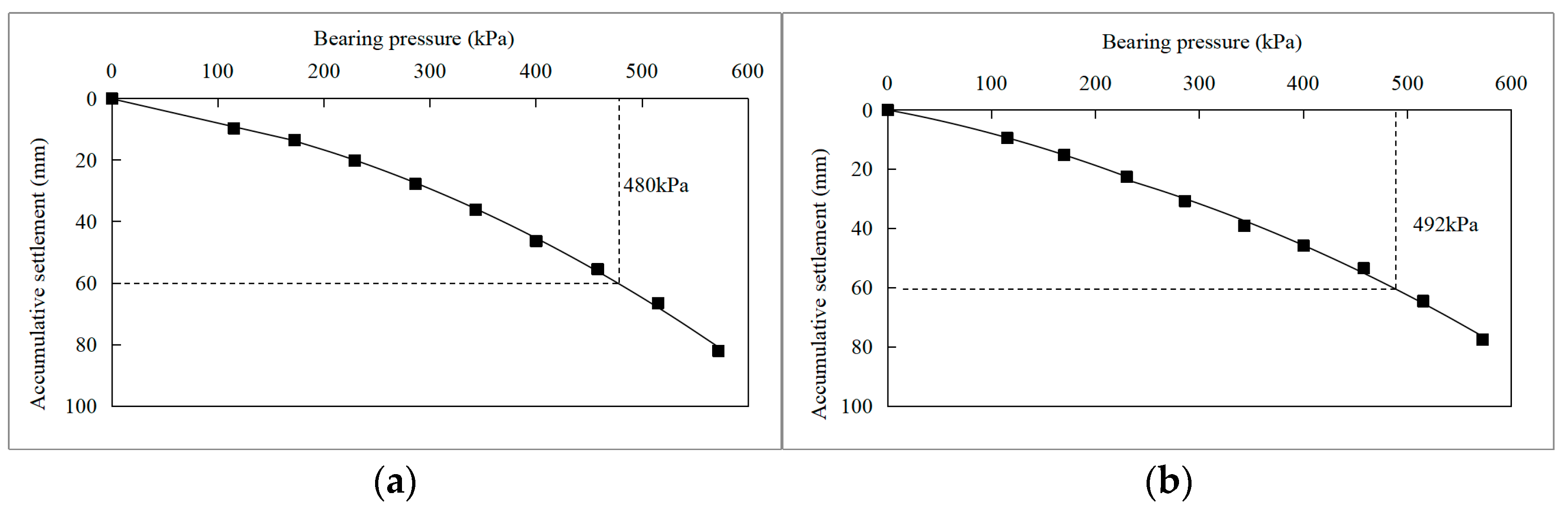
3.1.2. S2 and S3
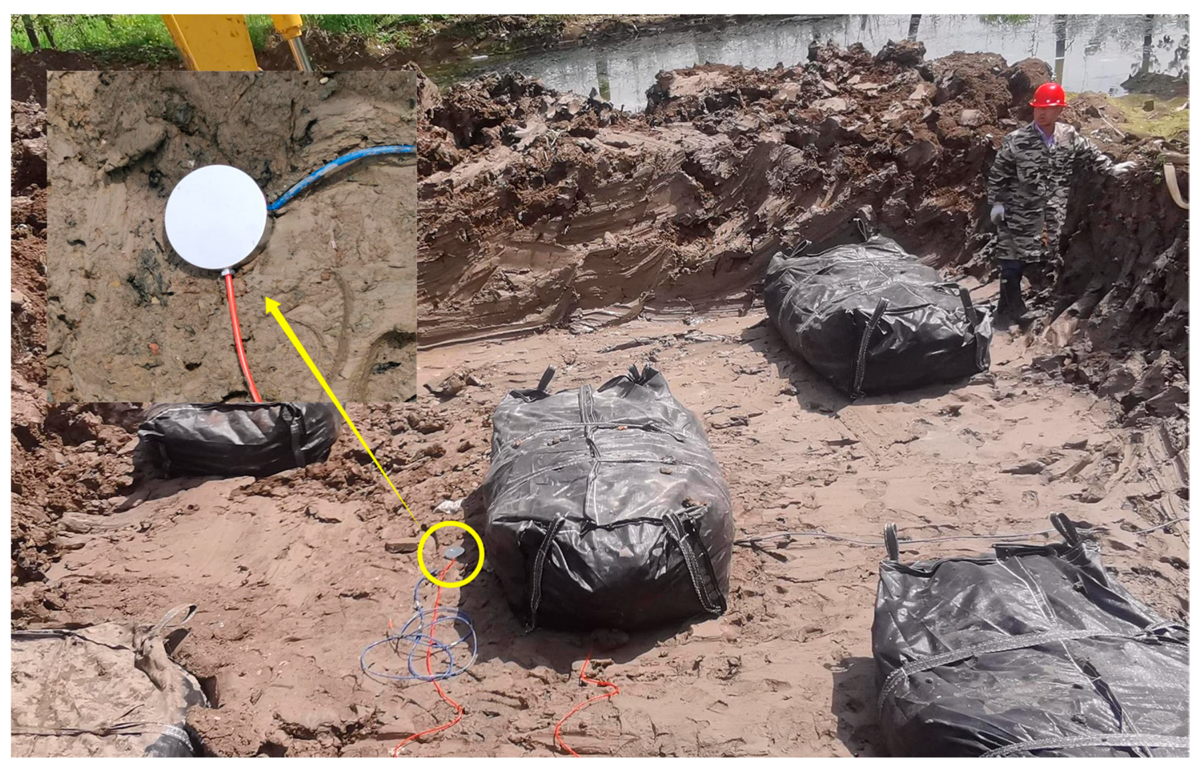
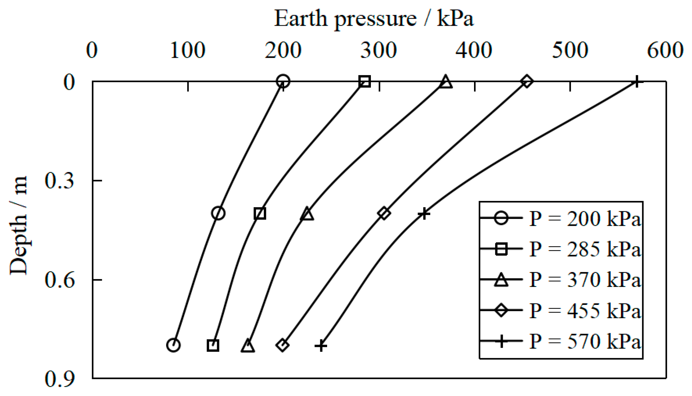
3.2. Earth Pressure Distribution
4. Discussion
5. Conclusions
- (1)
- Soilbags possess high strength due to the additional cohesion produced by the bag tension under external force. The feasibility of soilbag reinforcement technology in the soft foundation treatment is confirmed through plate load tests. Soilbag reinforcement using solid waste increases the bearing capacity of soft foundations and reduces settlement under external loads. Different solid residues can be used as the material contained in the soilbag, including excavated soil and brick slag residues, while the soilbag with plain fill mixed with brick slag has a better reinforcement effect than that with pure plain fill.
- (2)
- Soilbag technology combined with permeable treatment of bottom sludge is an effective foundation reinforcement method for deep silt soil bases. Furthermore, the number of soilbag layers required for the same reinforcement effect can be reduced by pressing a permeable soilbag layer in the bottom sludge under the same foundation conditions.
- (3)
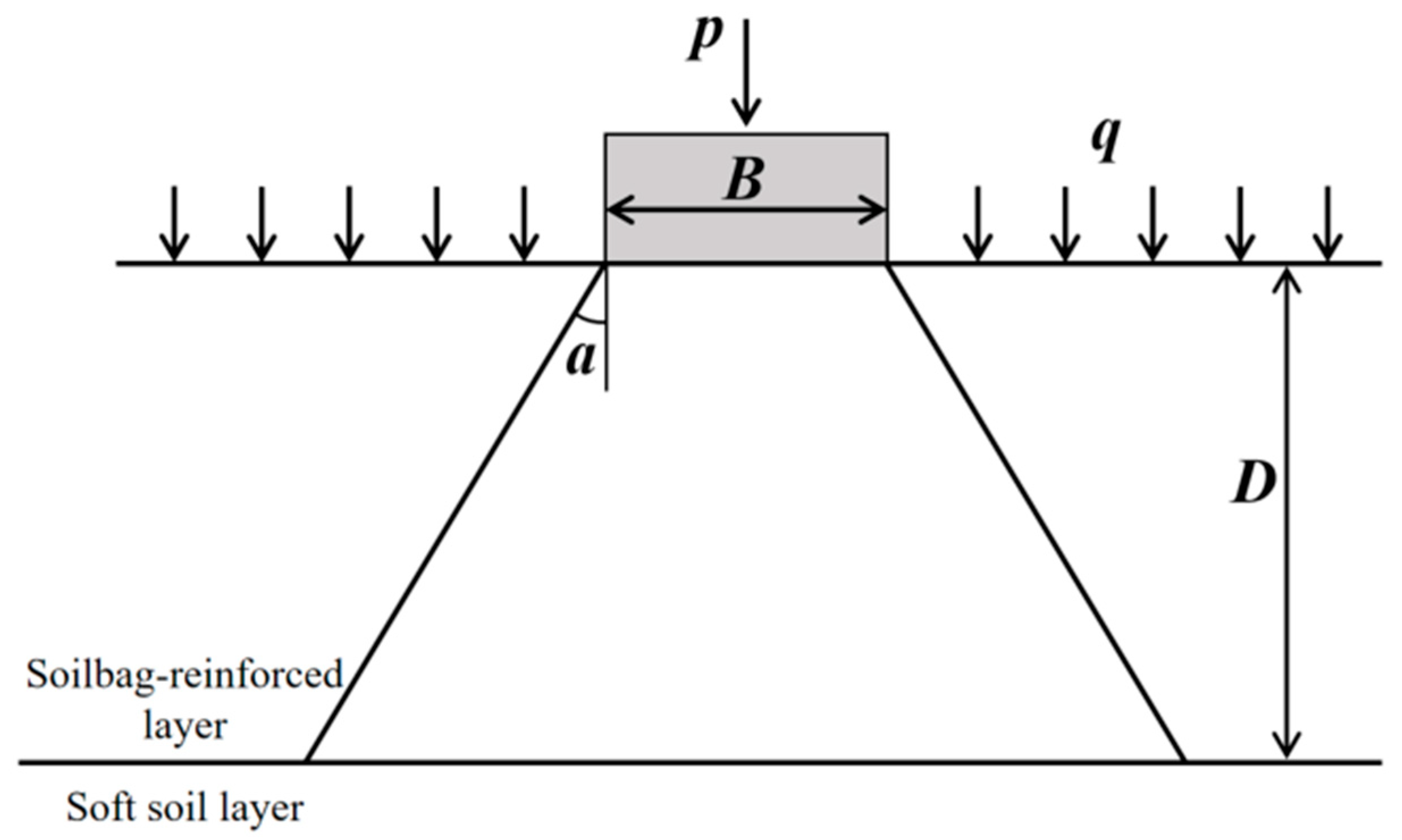
- The earth pressure decreases gradually with depth, indicating that the vertical load diffuses in the soilbag cushion. As the vertical load increases, the exertion of soilbag tension becomes more significant, the stiffness of the reinforcement layer increases, and the attenuation of soil pressure with depth becomes more pronounced. The earth pressure under the bearing plate is the largest at the same depth, and the earth pressure decreases with the horizontal distance from the center of the bearing plate. The stress diffusion angle of the soilbag reinforcement layer obtained from the tests is approximately 38°.
- (4)
- Compared to the conventional excavation and replacement approach, the soilbag reinforcement material can meet the construction requirements while offering many advantages, such as cost savings, a shorter construction period, high construction efficiency, and easy reclamation. In addition, soilbags infilled with solid wastes make full use of local materials while also being environmentally friendly. Therefore, soilbag technology has promising prospects for application in the construction of hoisting platforms for plain wind farms near lakes.
Author Contributions
Funding
Institutional Review Board Statement
Informed Consent Statement
Data Availability Statement
Conflicts of Interest
References
- Li, J.J.; Wu, Z.Q.; Tan, X.Q.; Chen, B. Review of wind power generation and relative technology development. Electr. Power Constr. 2011, 32, 64–72. [Google Scholar]
- Peng, X.; Liu, Z.; Jiang, D. A review of multiphase energy conversion in wind power generation. Renew. Sustain. Energy Rev. 2021, 147, 111172. [Google Scholar] [CrossRef]
- Vargas, S.A.; Esteves, G.R.T.; Maçaira, P.M.; Bastos, B.Q.; Oliveira, F.L.C.; Souza, R.C. Wind power generation: A review and a research agenda. J. Clean. Prod. 2019, 218, 850–870. [Google Scholar] [CrossRef]
- Li, Y.H.; Kong, L. Developing solar and wind power generation technology to accelerate China’s energy transformation. Scaled Util. Renew. Energy 2019, 34, 426–433. [Google Scholar]
- Gasch, R.; Twele, J. Wind Power Plants: Fundamentals, Design, Construction and Operation, 2nd ed.; Springer Science & Business Media: Berlin, Germany, 2011. [Google Scholar]
- Hu, Y.; Zhao, Z.; Zhang, P.; Jiang, H.; Lin, J. Study of replacement combine with reinforcement to treat soft ground under widened subgrade. J. Highw. Transp. Res. Dev. 2009, 26, 35–39. [Google Scholar]
- Rowe, R.K.; Taechakumthorn, C. Design of reinforced embankments on soft clay deposits considering the viscosity of both foundation and reinforcement. Geotext. Geomembr. 2011, 29, 448–461. [Google Scholar] [CrossRef]
- Kim, M.; Freeman, M.; FitzPatrick, B.T.; Nevius, D.B.; Plaut, R.H.; Filz, G.M. Use of an apron to stabilize geomembrane tubes for fighting floods. Geotext. Geomembr. 2004, 22, 239–254. [Google Scholar] [CrossRef]
- Liu, S.H. Principle and Practice of Soilbag Technology, 1st ed.; Science Press: Beijing, China, 2017. [Google Scholar]
- Ansari, Y.; Merifield, R.; Yamamoto, H.; Sheng, D. Numerical analysis of soilbags under compression and cyclic shear. Comput. Geotech. 2011, 38, 659–668. [Google Scholar] [CrossRef] [Green Version]
- Matsuoka, H.; Chen, Y.; Kodama, H.; Yamaji, Y.; Tanaka, R. Mechanical properties of soilbags and unconfined compression tests on model and real soilbags. In Proceedings of the 35th Japan National Conference on Geotechnical Engineering, Gifu, Japan, 2000; Volume 544, pp. 1075–1076. [Google Scholar]
- Matsuoka, H.; Liu, S.H. New earth reinforcement method by soilbags (‘Donow’). Soils Found. 2003, 43, 173–188. [Google Scholar] [CrossRef] [Green Version]
- Liu, S.H.; Gao, J.J.; Wang, Y.Q.; Weng, L.P. Experimental study on vibration reduction by using soilbags. Geotext. Geomembr. 2014, 42, 52–62. [Google Scholar] [CrossRef]
- Shen, C.M.; Fan, K.W.; Liu, S.H.; Wang, L.J.; Lai, Z.Q.; Yuan, W.H. A simple unified stress-strain model for geotextile-wrapped soils. Geotext. Geomembr. 2021, 49, 697–706. [Google Scholar] [CrossRef]
- Wang, Y.Q.; Li, X.; Liu, K.; Liu, G. Experiments and DEM analysis on vibration reduction of soilbags. Geosynth. Int. 2019, 26, 551–562. [Google Scholar] [CrossRef]
- Li, Z.; Liu, S.H.; Wang, L.J. Experimental study on the effect of frost heave prevention using soilbags. Cold Reg. Sci. Technol. 2013, 85, 109–116. [Google Scholar] [CrossRef]
- Li, Z.; Liu, S.H.; Wang, L.J.; Fu, Z.Z. Experimental study on the mechanical properties of clayey soil under different freezing apparatus temperatures and freeze-thaw cycles. Sci. Iran. 2014, 20, 1145–1152. [Google Scholar]
- Martinelli, L.; Zanuttigh, B.; Nigris, N.D.; Preti, M. Sand bag barriers for coastal protection along the Emilia Romagna littoral, northern Adriatic Sea, Italy. Geotext. Geomembr. 2011, 29, 370–380. [Google Scholar] [CrossRef] [Green Version]
- Recio, J.; Oumeraci, H. Effect of deformations on the hydraulic stability of coastal structures made of geotextile sand containers. Geotext. Geomembr. 2007, 25, 278–292. [Google Scholar] [CrossRef]
- Jia, F.; Liu, S.H.; Shen, C.M.; Sun, Y. Predicting strength of soilbags under cyclic compression. Geosynth. Int. 2020, 27, 646–654. [Google Scholar] [CrossRef]
- Liu, S.H.; Fang, B.X.; Lu, Y.; Chen, S. Behaviour of soilbags subjected to monotonic and cyclic vertical loading. Geosynth. Int. 2023, 30, 81–94. [Google Scholar] [CrossRef]
- Rowe, R.K.; Skinner, G.D. Numerical analysis of geosynthetic reinforced retaining wall constructed on a layered soil foundation. Geotext. Geomembr. 2001, 19, 387–412. [Google Scholar] [CrossRef]
- Liu, S.H.; Fan, K.W.; Xu, S.Y. Field study of a retaining wall constructed with clay-filled soilbags. Geotext. Geomembr. 2019, 49, 87–94. [Google Scholar] [CrossRef]
- Shao, J.X.; Huang, J.; Zhou, B.M. Application of soil bags in subgrade engineering. Highway 2005, 7, 82–86. [Google Scholar]
- Xu, Y.F.; Zhou, B.M.; Tong, L.X. Tests on soilbags. J. Highw. Transp. Res. Dev. 2007, 9, 84–88. [Google Scholar]
- Restalla, S.J.; Jacksonb, L.A.; Heerten, G.; Hornsey, W.P. Case studies showing the growth and development of geotextile sand containers: An Australian perspective. Geotext. Geomembr. 2002, 20, 321–342. [Google Scholar] [CrossRef]
- Liu, S.H.; Bai, F.Q.; Wang, Y.S.; Wang, S.; Li, Z. Treatment for expansive soil channel slope with soilbags. J. Aerosp. Eng. 2012, 26, 657–666. [Google Scholar] [CrossRef] [Green Version]
- Liu, S.H.; Gao, C.R.; Fan, K.W.; Zhang, C.B.; Wang, Z.J.; Shen, C.M.; Han, Z. Repairing expansive soil channel slope with soilbags. Geosynth. Int. 2022, 1–10. [Google Scholar] [CrossRef]
- Wang, L.J.; Liu, S.H.; Liao, J.; Fan, K.W. Field load tests and modelling of soft foundation reinforced by soilbags. Geosynth. Int. 2019, 26, 580–591. [Google Scholar] [CrossRef]
- Basudhar, P.K.; Dixit, P.M.; Gharpure, A.; Deb, K. Finite element analysis of geotextile-reinforced sand-bed subjected to strip loading. Geotext. Geomembr. 2008, 26, 91–99. [Google Scholar] [CrossRef]
- Indraratna, B.; Nimbalkar, S.; Christie, D.; Rujikiatkamjorn, C.; Vinod, J. Field assessment of the performance of a ballasted rail track with and without geosynthetics. J. Geotech. Geoenviron. Eng. 2010, 136, 907–917. [Google Scholar] [CrossRef]
- Liu, S.H.; Matsuoka, H. A new earth reinforcement method by soilbags. Rock Soil Mech. 2007, 28, 1665–1670. [Google Scholar]
- Matsuoka, H.; Liu, S.H. A New Earth Reinforcement Method Using Soil Bags; Taylor & Francis/Balkema: Rotterdam, The Netherlands, 2017. [Google Scholar]
- Xu, Y.F.; Huang, J.; Du, Y.J.; Sun, D.A. Earth reinforcement using soilbags. Geotext. Geomembr. 2008, 26, 279–289. [Google Scholar] [CrossRef]
- Bai, F.Q.; Liu, S.H.; Xu, J.Q.; Liu, X.J.; Gao, L.H. In situ plate load tests on the soilbag reinforced expansive soil foundation. Adv. Mater. Res. 2013, 718–720, 1888–1894. [Google Scholar] [CrossRef]
- Hataf, N.; Sayadi, M. Experimental and numerical study on the bearing capacity of soils reinforced using geobags. J. Build. Eng. 2018, 15, 290–297. [Google Scholar] [CrossRef]
- Ministry of Housing and Urban-Rural Development of the People’s Republic of China. Code for Design of Wind Farm: GB 51096-2015; China Architecture Publishing & Media: Beijing, China, 2015. [Google Scholar]
- Ministry of Housing and Urban-Rural Development of the People’s Republic of China. Technical Code for Ground Treatment of Buildings: JGJ 79-2012; China Architecture Publishing & Media: Beijing, China, 2012. [Google Scholar]
- Fan, K.; Liu, S.H.; Cheng, Y.P.; Wang, Y. Sliding stability analysis of a retaining wall constructed by soilbags. Géotech. Lett. 2019, 9, 211–217. [Google Scholar] [CrossRef]
- Fan, K.; Liu, S.H.; Cheng, Y.P.; Liao, J. Effect of infilled materials and arrangements on shear characteristics of stacked soilbags. Geosynth. Int. 2020, 27, 662–670. [Google Scholar] [CrossRef]
- General Administration of Quality Supervision, Inspection and Quarantine of the People’s Republic of China. General Technical Requirements of Plastic Woven Sack: GB/T 8946-2013; China Architecture Publishing & Media: Beijing, China, 2013. [Google Scholar]
- General Administration of Quality Supervision, Inspection and Quarantine of the People’s Republic of China. Plastics—Methods of Exposure to Laboratory Light Sources: GB/T 16422.2-2014; China Architecture Publishing & Media: Beijing, China, 2014. [Google Scholar]
- Terzaghi, K.; Peck, R.B. Soil Mechanics in Engineering Practice; John Wiley and Sons Publication: New York, NY, USA, 1948. [Google Scholar]
- Gong, X.N. Composite Foundation Theory and Engineering Application; China Architecture & Building Press: Beijing, China, 2007. [Google Scholar]
- Ministry of Housing and Urban-Rural Development of the People’s Republic of China. Code for Design of Building Foundation: GB 50007-2011; China Architecture Publishing & Media: Beijing, China, 2011. [Google Scholar]


| Stratum No. | Stratum Name | Thickness (m) | SPT Blow Count | Characteristic Value of Bearing Capacity (kPa) | Cohesion (kPa) | Angle of Internal Friction (°) |
|---|---|---|---|---|---|---|
| ① | Plain fill | 2.2 | ~ | 60 | 32 | 7.5 |
| ③ | Clay mixed with silty clay | 6.3 | 8~12 | 180 | 62.6 | 11.7 |
| ③−1 | Silt | 3.6 | 15~17 | 170 | 3.1 | 32.1 |
| ④ | Clay mixed with silty clay | 9 | 10~12 | 240 | 90.1 | 14.5 |
| ④−1 | Silt | 2.1 | 16 | 190 | 5.8 | 30.3 |
| ⑤ | Silty clay | 3.8 | 9~10 | 180 | 54.3 | 10.8 |
| Stratum No. | Stratum Name | Thickness (m) | SPT Blow Count | Characteristic Value of Bearing Capacity (kPa) | Cohesion (kPa) | Angle of Internal Friction (°) |
|---|---|---|---|---|---|---|
| ① | Plain fill | 0.6 | ~ | 60 | 32.0 | 7.5 |
| ② | Muddy soil | 2.8 | 1 | 50 | 7.6 | 1.7 |
| ③ | Clay mixed with silty clay | 8.6 | 8~13 | 180 | 62.6 | 11.7 |
| ④−1 | Silt | 4.0 | 17~22 | 190 | 5.8 | 30.3 |
| ④ | Clay mixed with silty clay | 7.6 | 11~14 | 240 | 90.1 | 14.5 |
| ⑤ | Silty clay | 5.7 | 10~12 | 180 | 54.3 | 10.8 |
| Loads p at Each Stage (kPa) | 115 | 200 | 285 | 370 | 455 | 540 | 570 | |
|---|---|---|---|---|---|---|---|---|
| Accumulative settlement s (mm) | S1a | 8.94 | 18.63 | 26.02 | 34.44 | 44.27 | 57.04 | 61.69 |
| S1b | 10.09 | 20.32 | 31.44 | 43.67 | 54.88 | 70.33 | 79.68 | |
| Loads p at Each Stage (kPa) | 115 | 170 | 230 | 285 | 345 | 400 | 455 | 515 | 570 | |
|---|---|---|---|---|---|---|---|---|---|---|
| Accumulative settlement s (mm) | S2 | 9.65 | 13.45 | 20.12 | 27.78 | 36.11 | 46.23 | 55.49 | 66.44 | 81.98 |
| S3 | 9.42 | 15.21 | 22.56 | 30.67 | 39.12 | 45.82 | 53.43 | 64.32 | 77.77 | |
| No. | Resource | Bearing Capacity/kPa | Number of Soilbag Layers | Dimension of Soilbags | Infill Material for Soilbags | |
|---|---|---|---|---|---|---|
| Unreinforced Foundation | Soilbag-Reinforced Foundation | |||||
| 1 | S1a | 60 | 245 | 2 | 2 m × 1 m × 0.5 m | excavated plain fill |
| 2 | S1b | 60 | 282.5 | 2 | plain fill with brick slag | |
| 3 | S2 | 50 | 240 | 5 | plain fill with brick slag | |
| 4 | Xu, 2008 | 70 | 160 | 2 | 0.5 m × 0.5 m × 0.1 m | sand |
| 5 | 70 | 240 | 3 | sand | ||
| 6 | Wang, 2019 | 96 | 135 | 2 | 0.4 m × 0.4 m × 0.1 m | excavated sandy clay |
| 7 | 96 | 170 | 4 | excavated sandy clay | ||
Disclaimer/Publisher’s Note: The statements, opinions and data contained in all publications are solely those of the individual author(s) and contributor(s) and not of MDPI and/or the editor(s). MDPI and/or the editor(s) disclaim responsibility for any injury to people or property resulting from any ideas, methods, instructions or products referred to in the content. |
© 2023 by the authors. Licensee MDPI, Basel, Switzerland. This article is an open access article distributed under the terms and conditions of the Creative Commons Attribution (CC BY) license (https://creativecommons.org/licenses/by/4.0/).
Share and Cite
Zhang, C.; Liao, J.; Zhang, Y.; Wang, L. Plate Load Tests of Soft Foundations Reinforced by Soilbags with Solid Wastes for Wind Farms. Materials 2023, 16, 4173. https://doi.org/10.3390/ma16114173
Zhang C, Liao J, Zhang Y, Wang L. Plate Load Tests of Soft Foundations Reinforced by Soilbags with Solid Wastes for Wind Farms. Materials. 2023; 16(11):4173. https://doi.org/10.3390/ma16114173
Chicago/Turabian StyleZhang, Chenchen, Jie Liao, Yuchi Zhang, and Liujiang Wang. 2023. "Plate Load Tests of Soft Foundations Reinforced by Soilbags with Solid Wastes for Wind Farms" Materials 16, no. 11: 4173. https://doi.org/10.3390/ma16114173