
Quasistatic Analysis of Precast Segmental Concrete-Filled Steel-Tube Bridge Pier with External Arched Energy Dissipation Device
 ,
,
Abstract
:1. Introduction
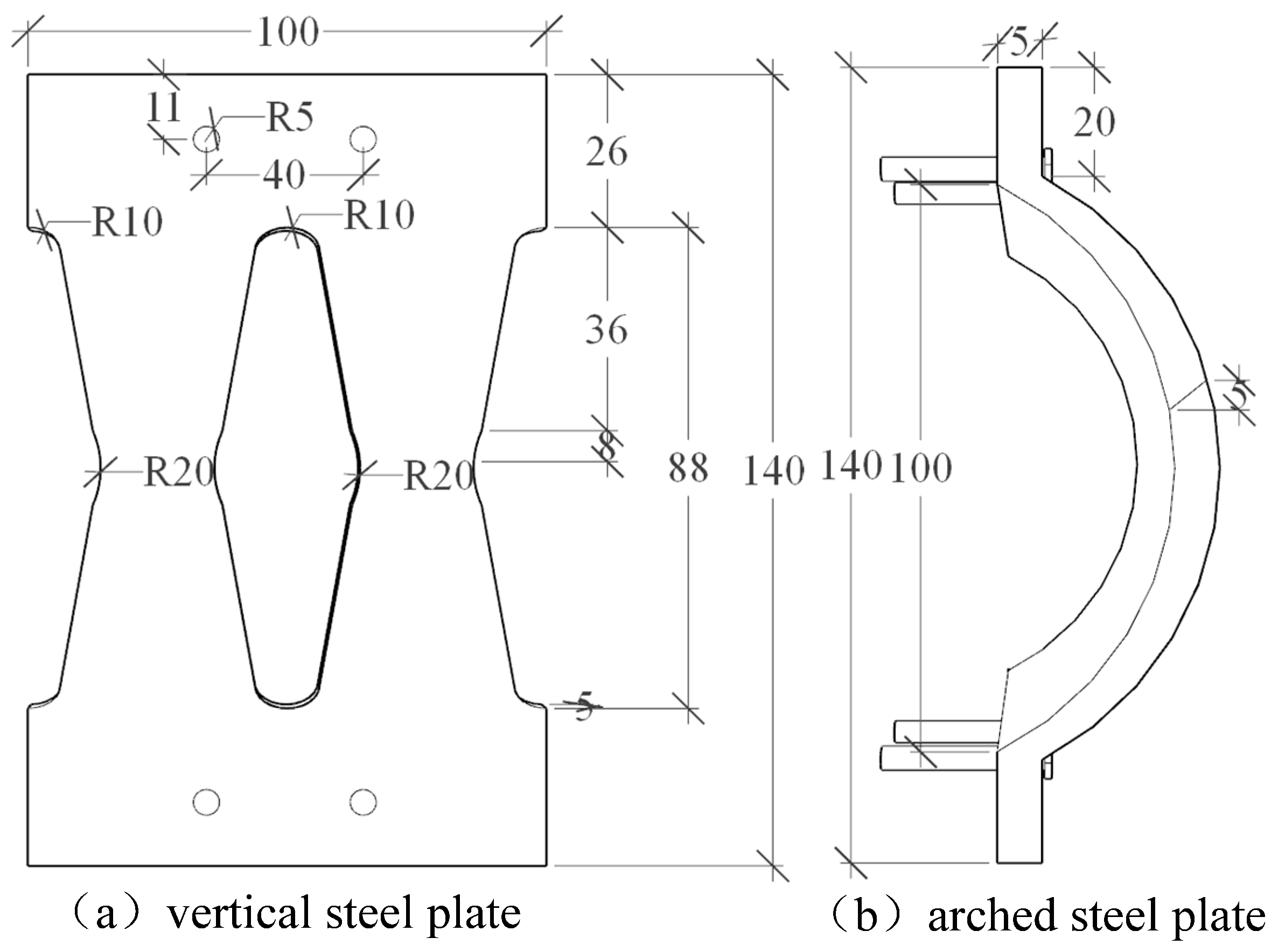
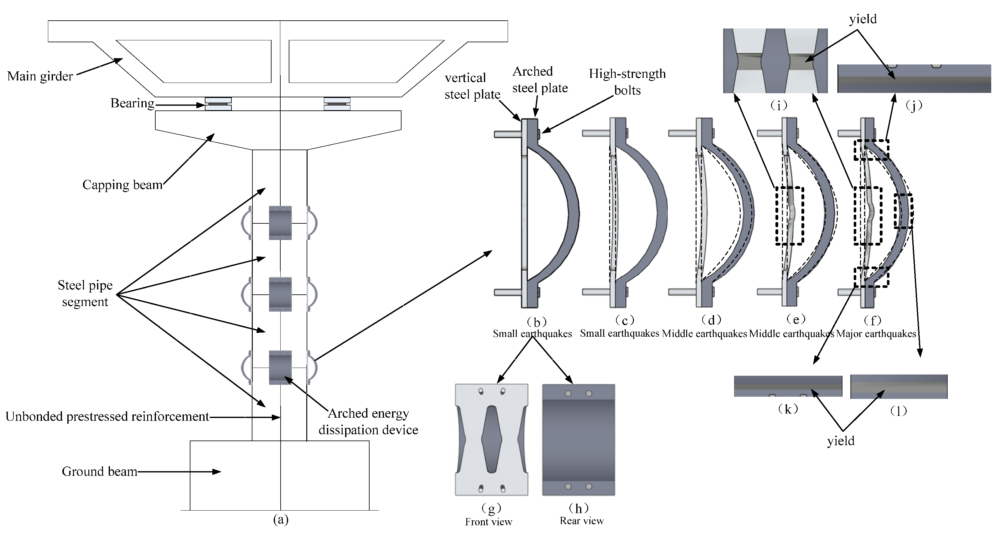
2. Design of AEDD
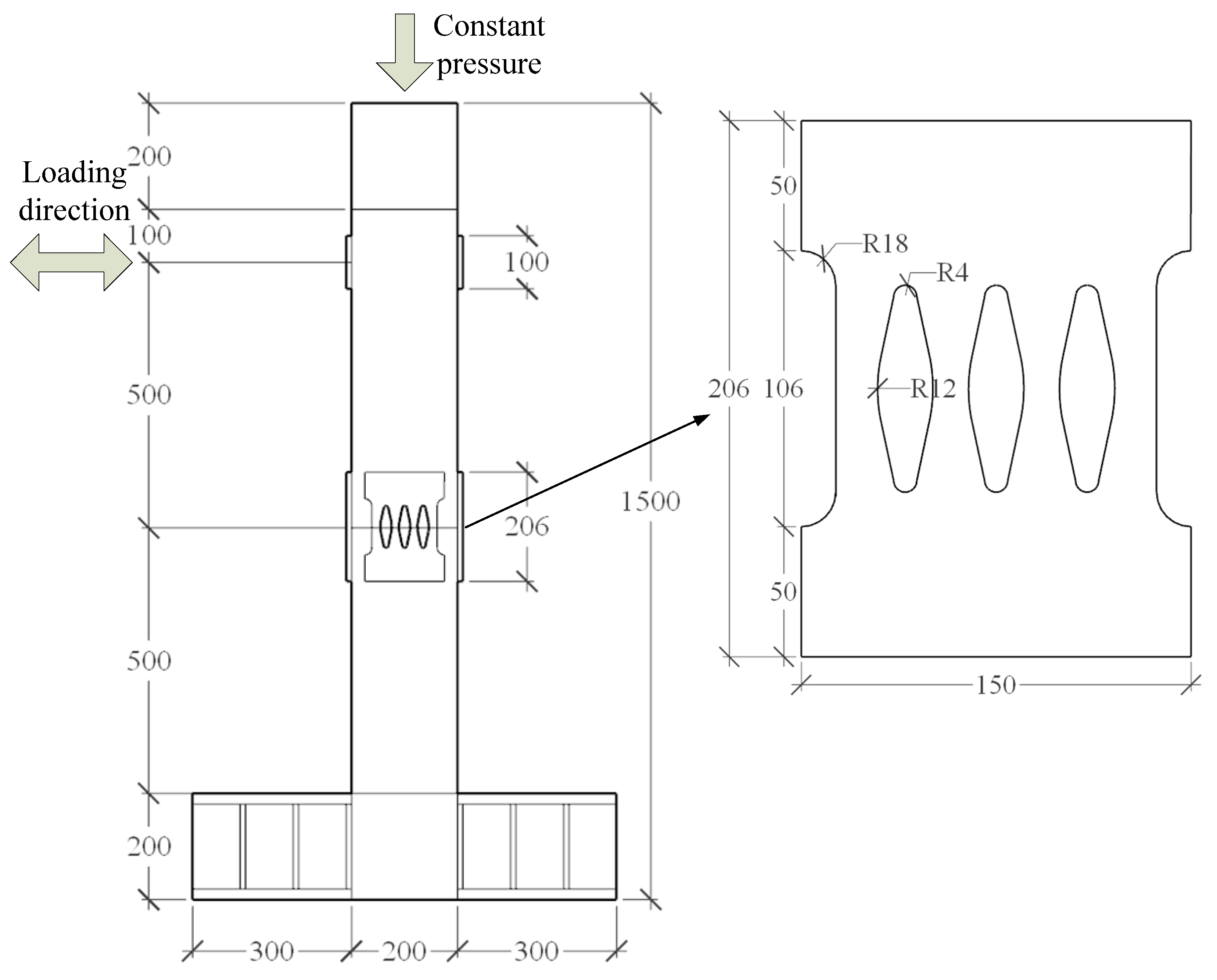
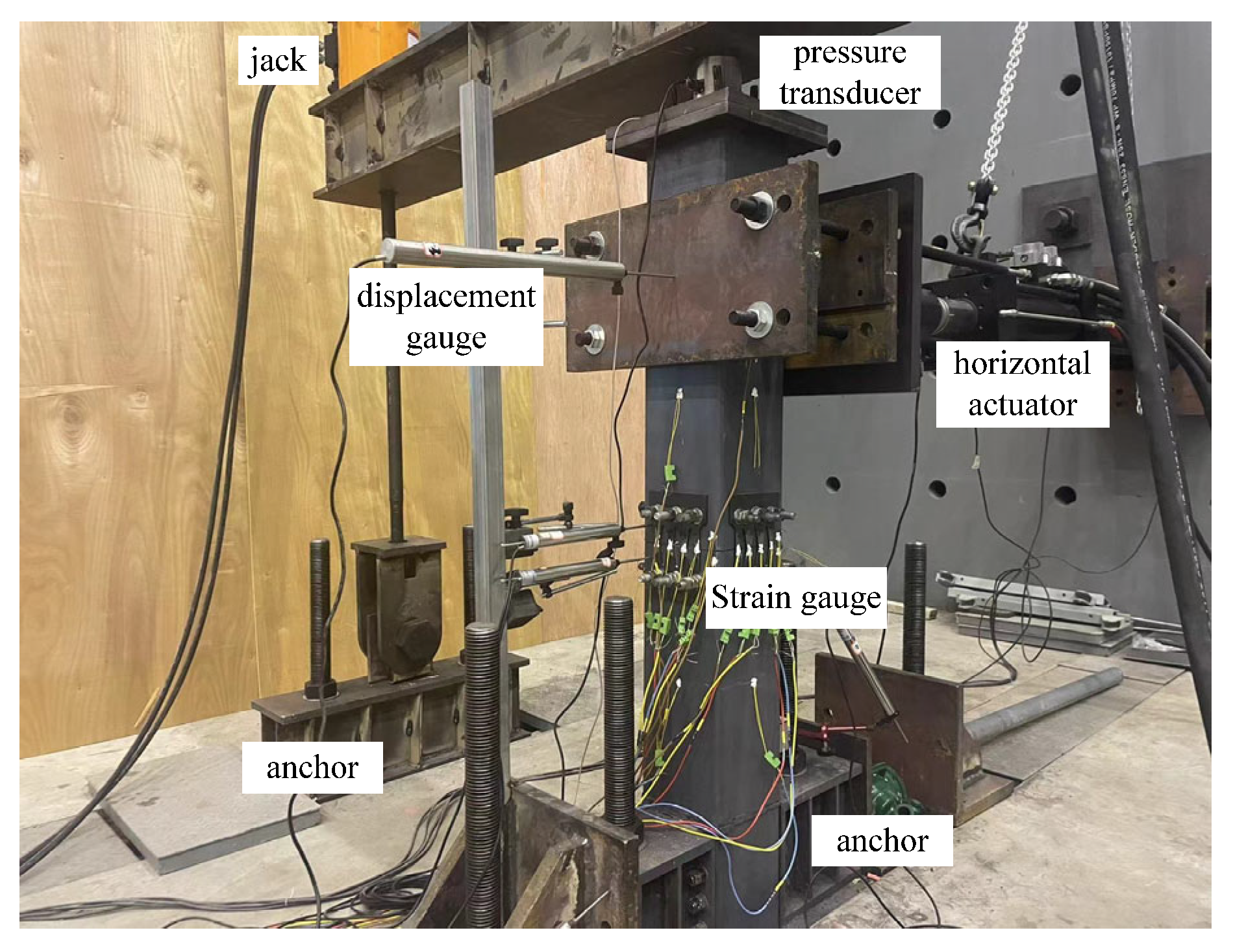
3. Finite-Element Numerical Simulation and Test Verification
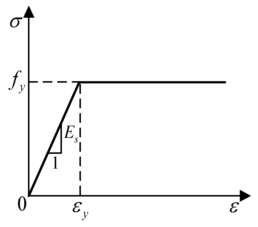
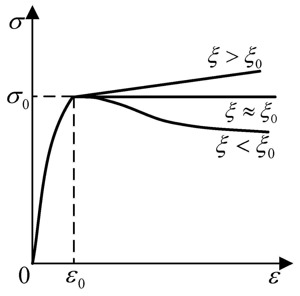
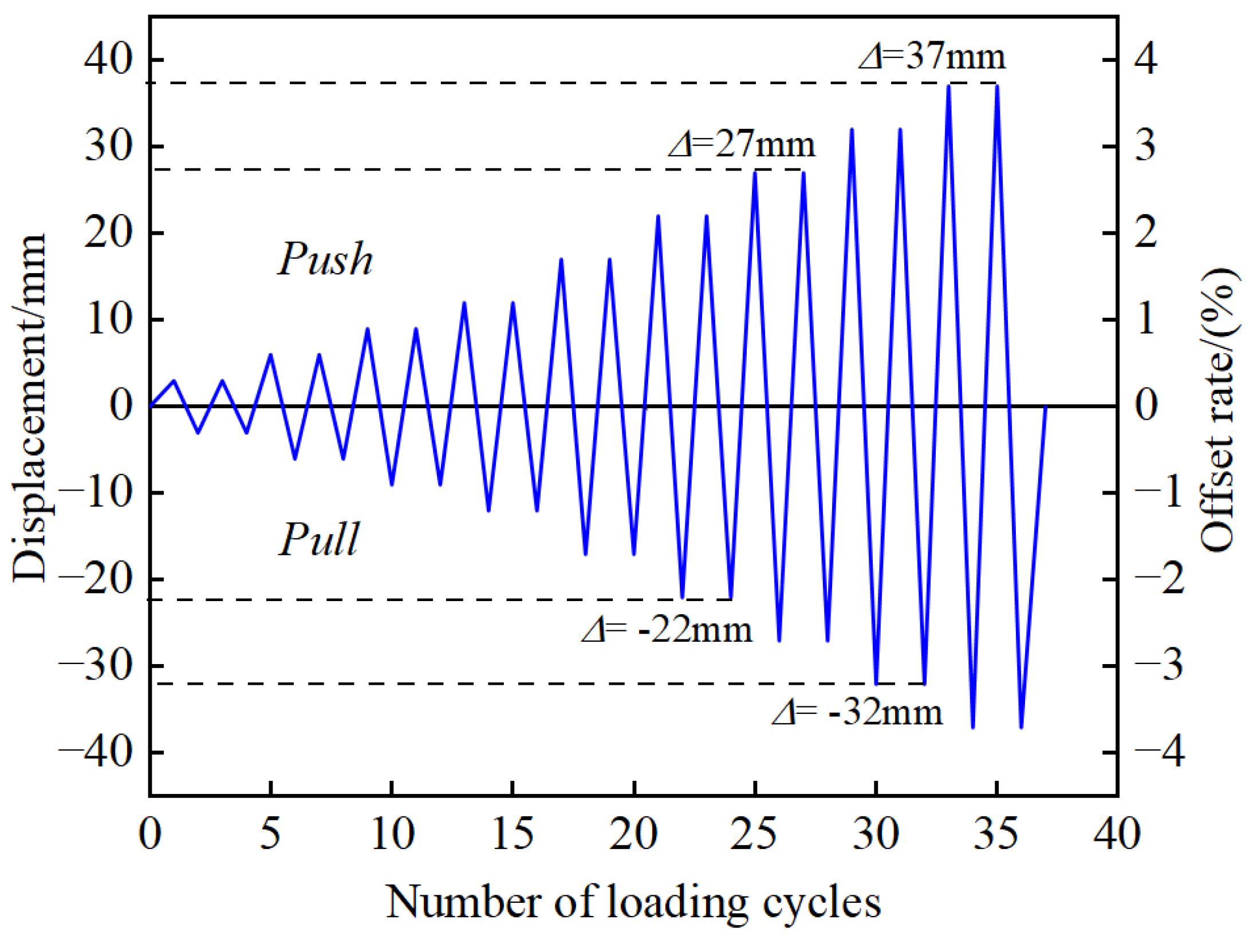
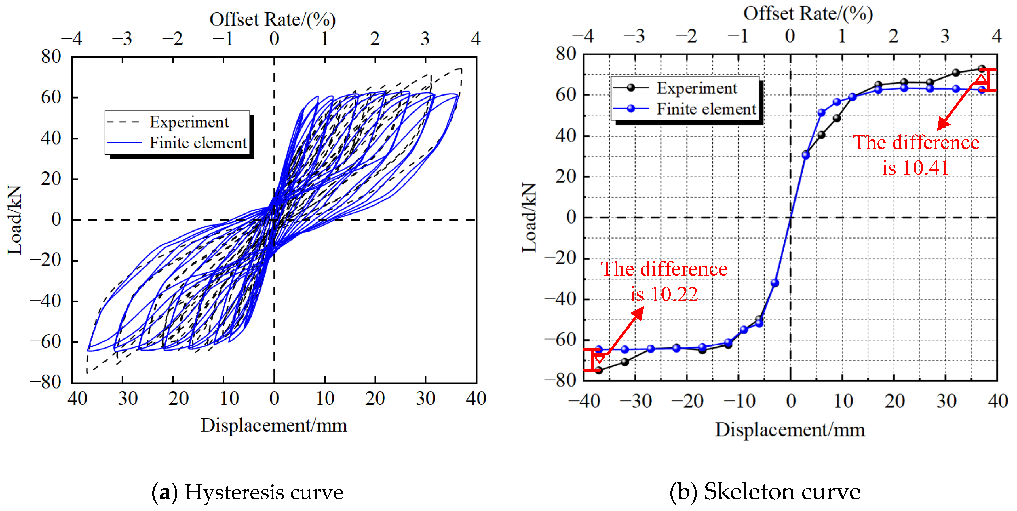
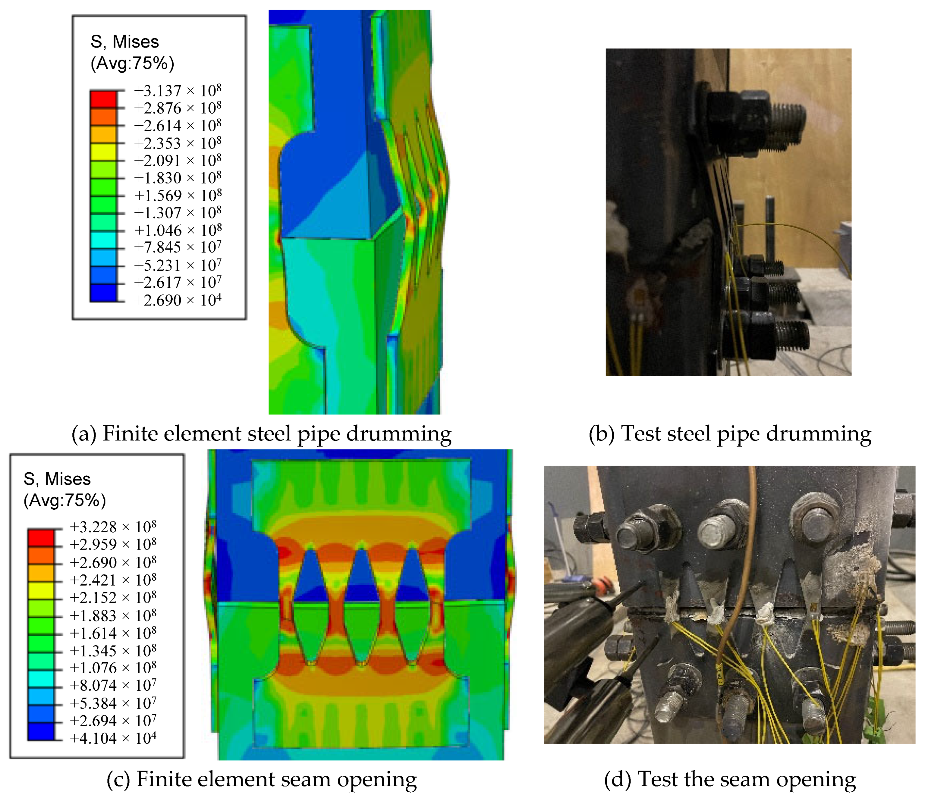
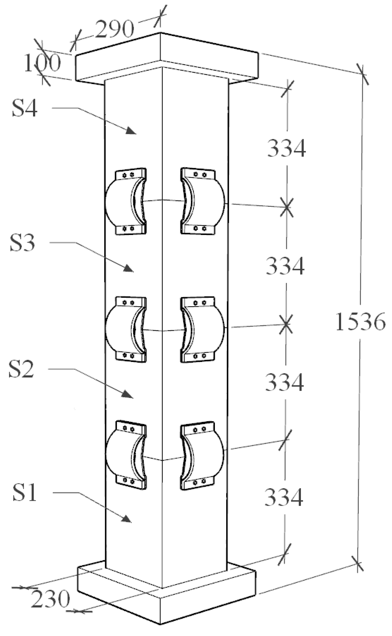
3.1. PSCFSTBP Finite-Element Model Verification
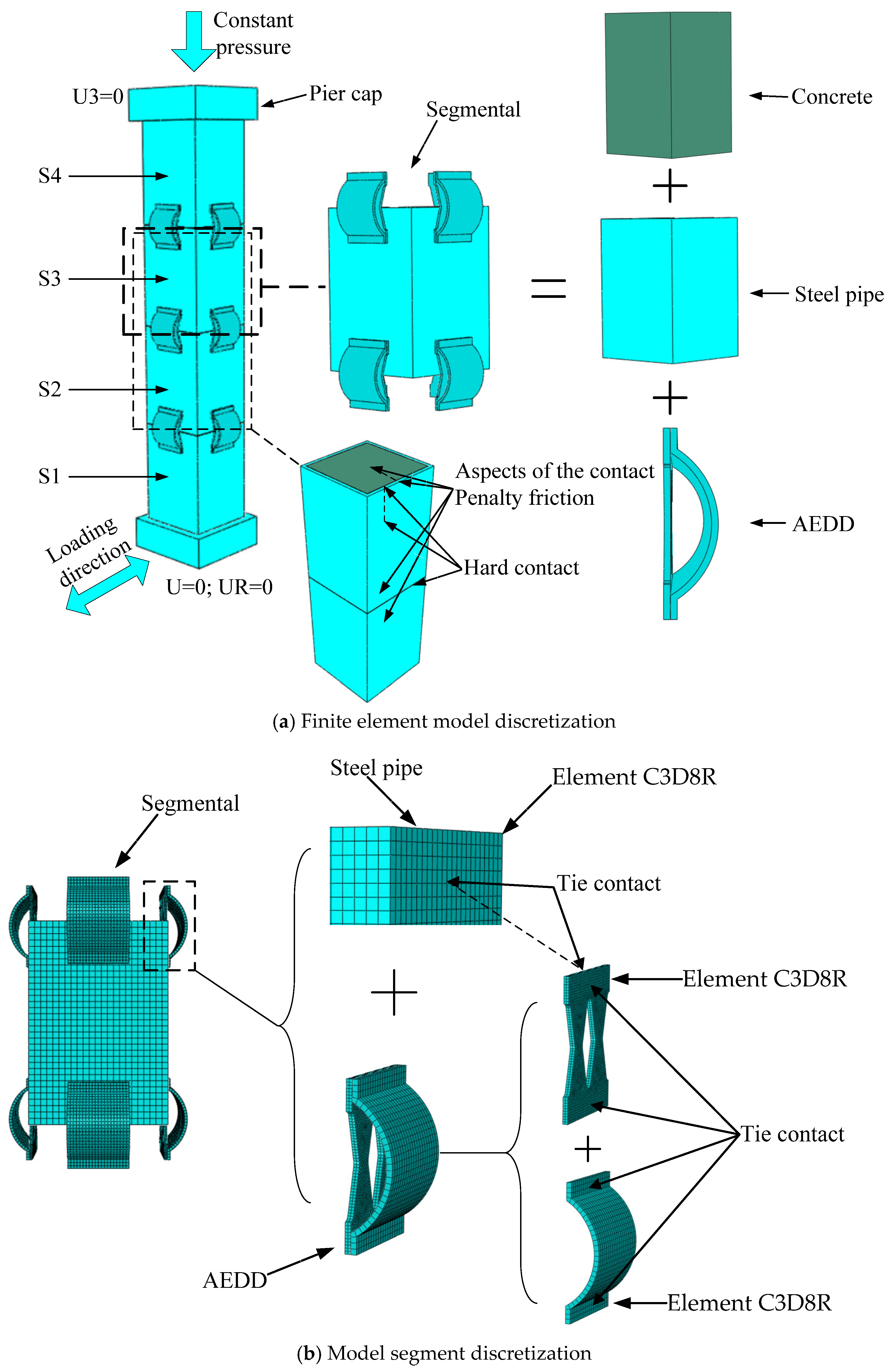
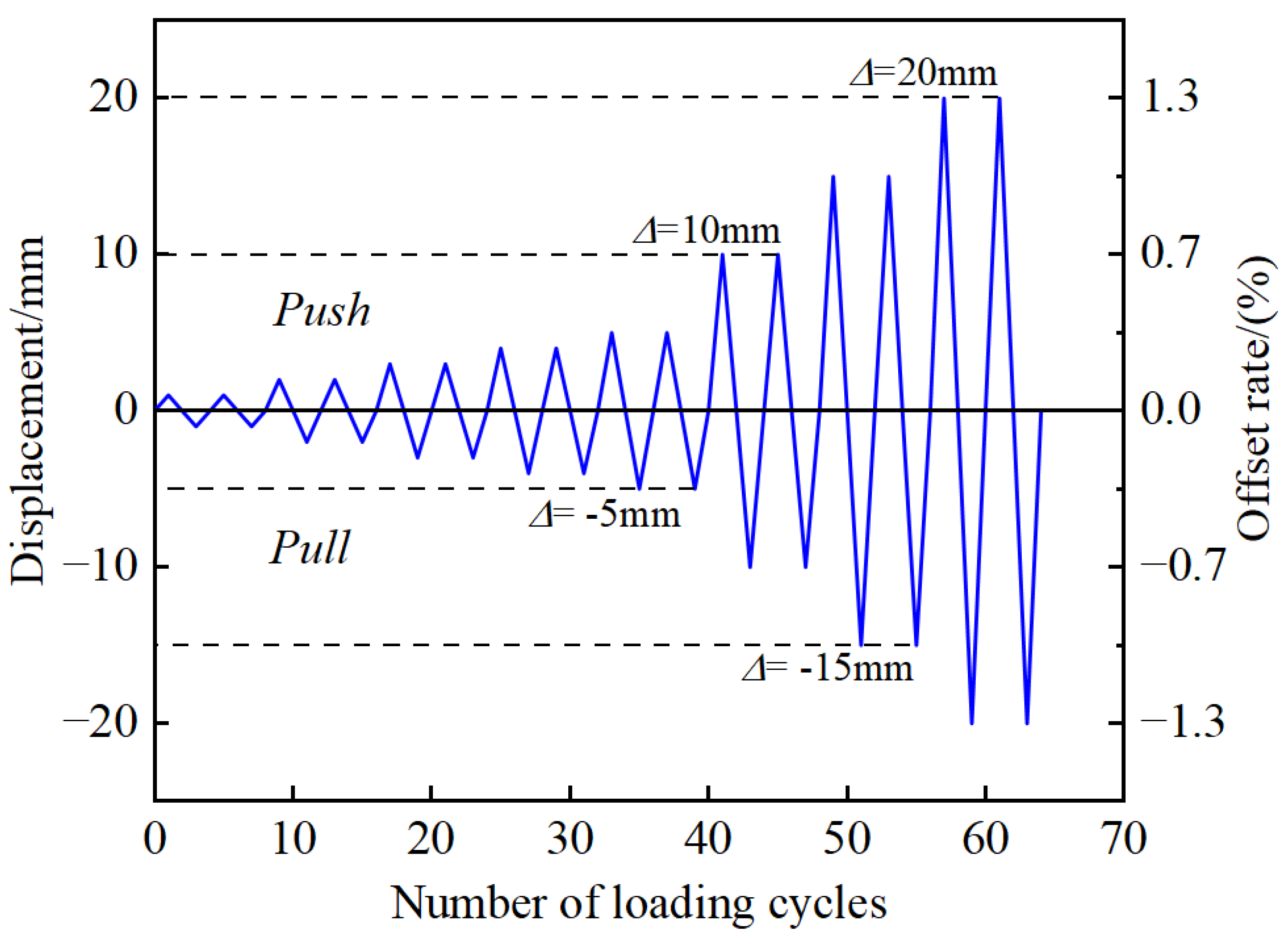
3.2. Establishment of PSCFSTBP Finite-Element Model of External AEDD
4. Structural Optimization Analysis of External Arch Device
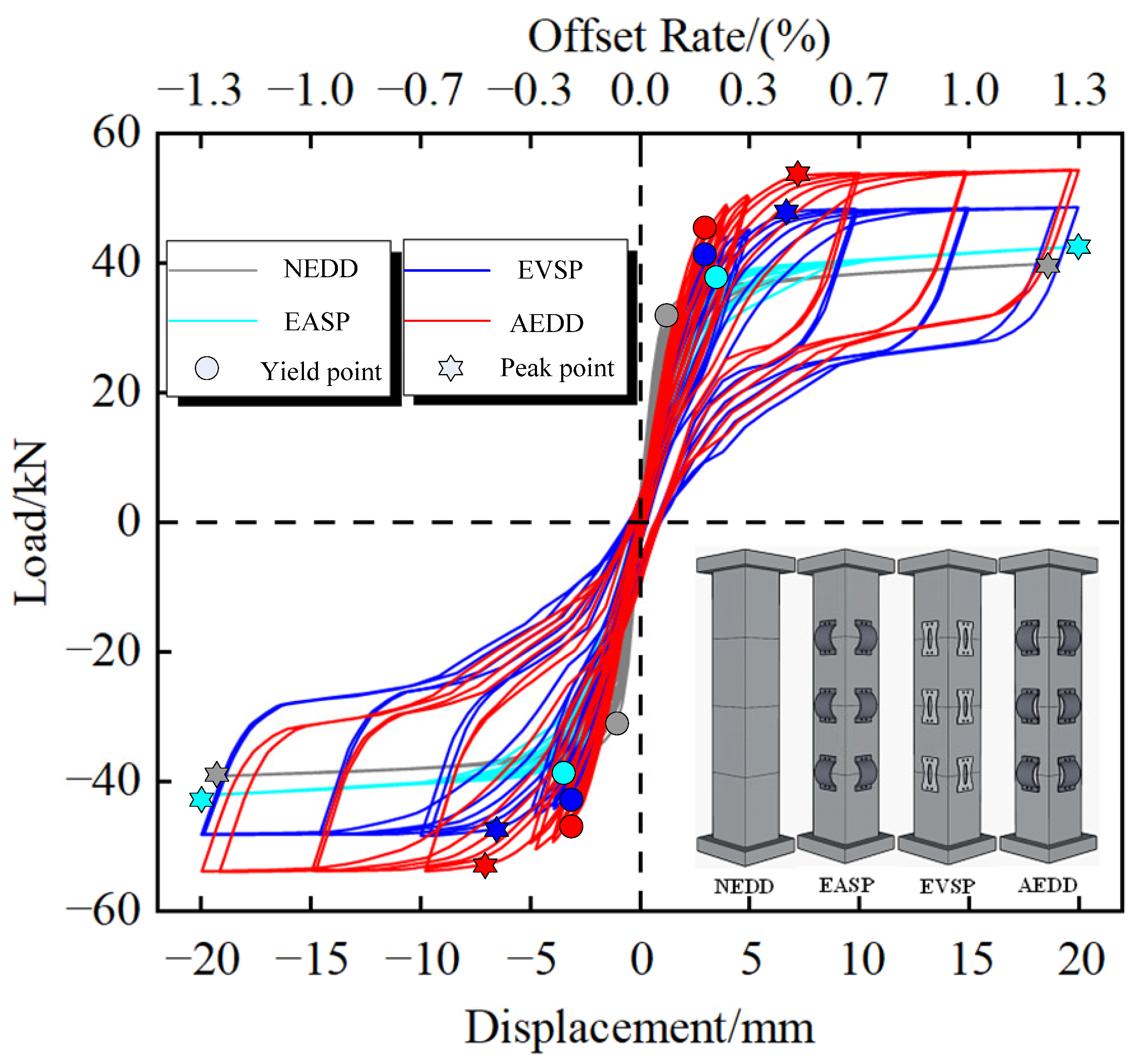
4.1. Hysteresis Curve
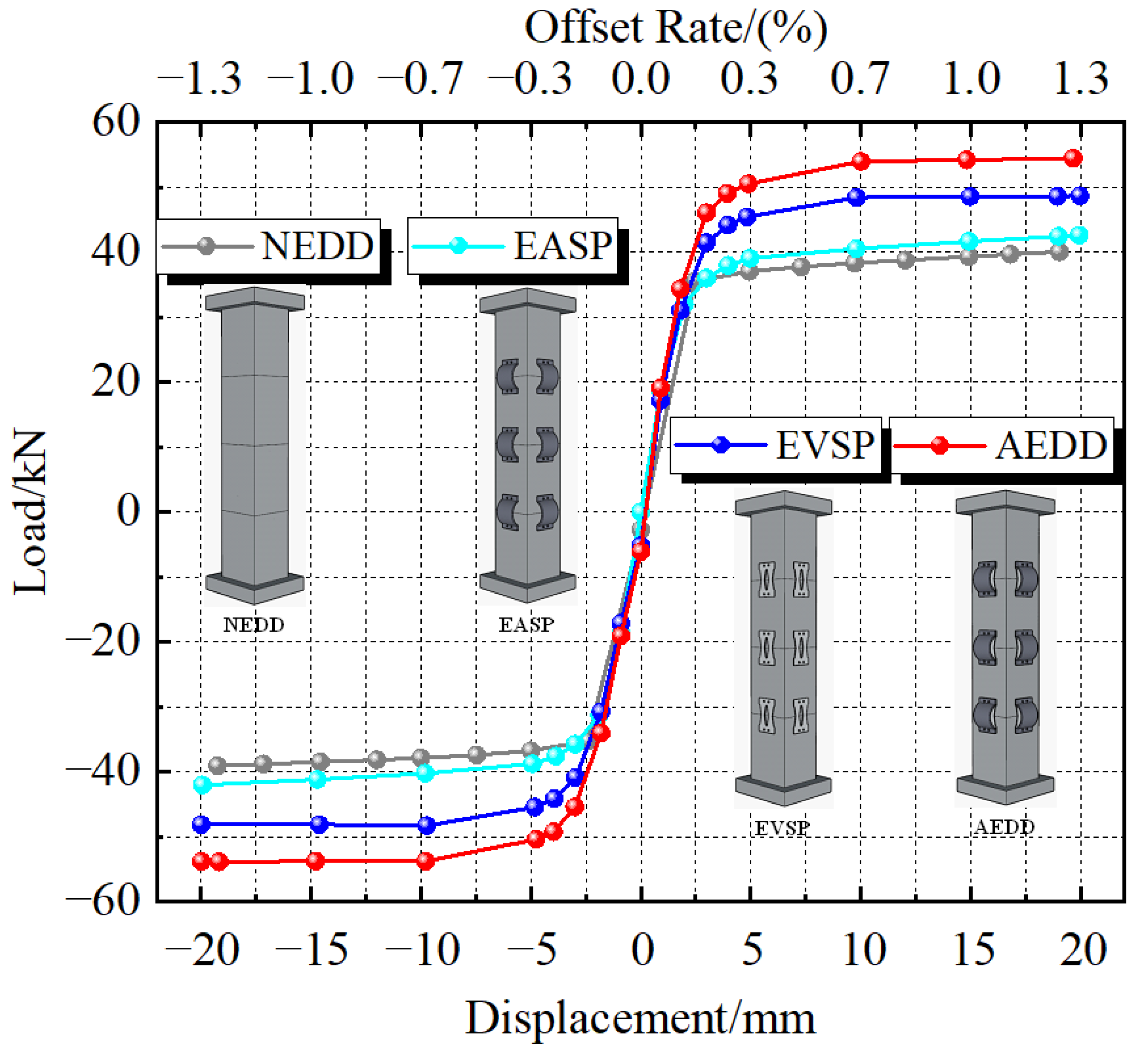
4.2. Skeleton Curve
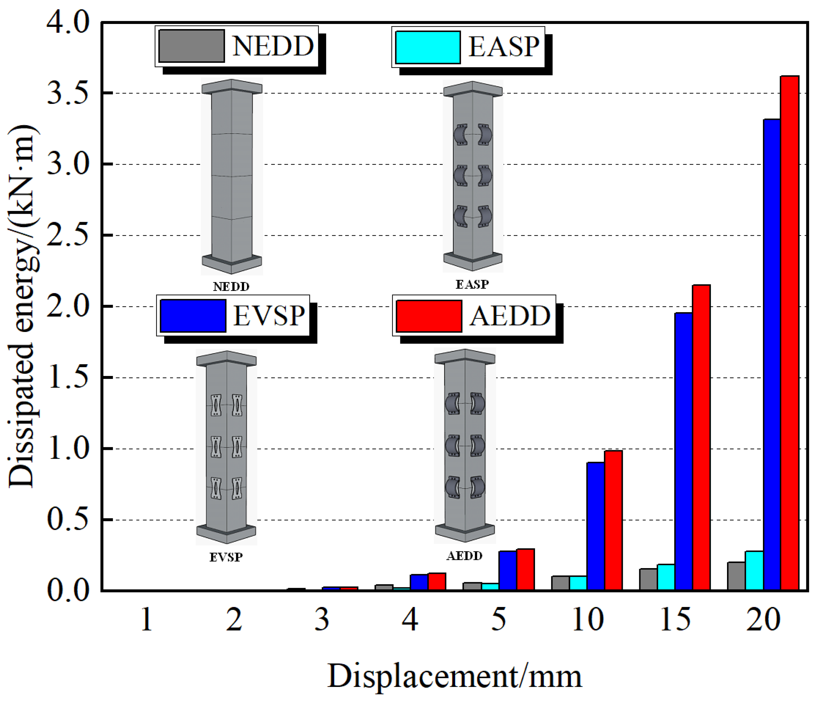
4.3. Cumulative Energy Consumption
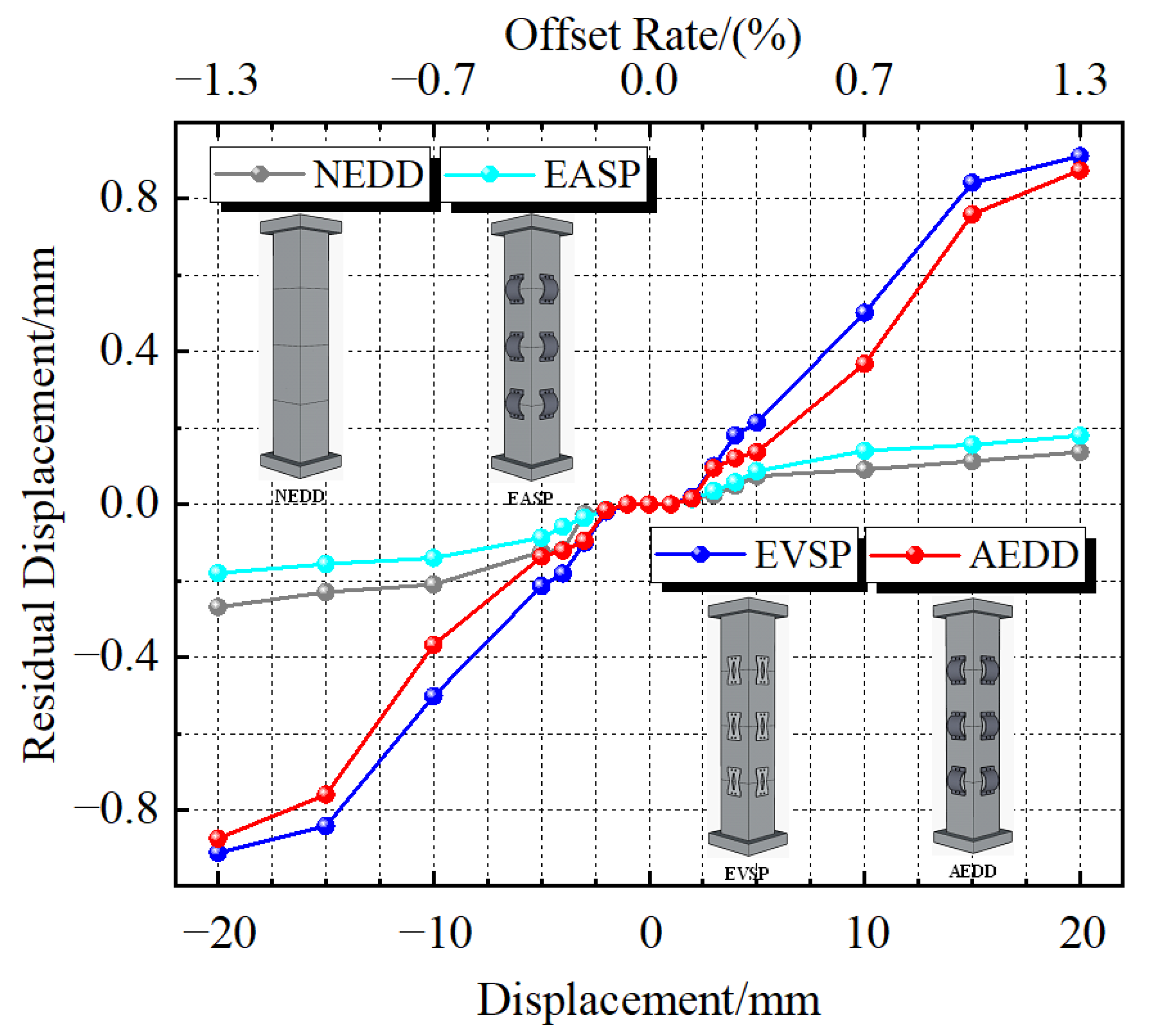
4.4. Residual Displacement
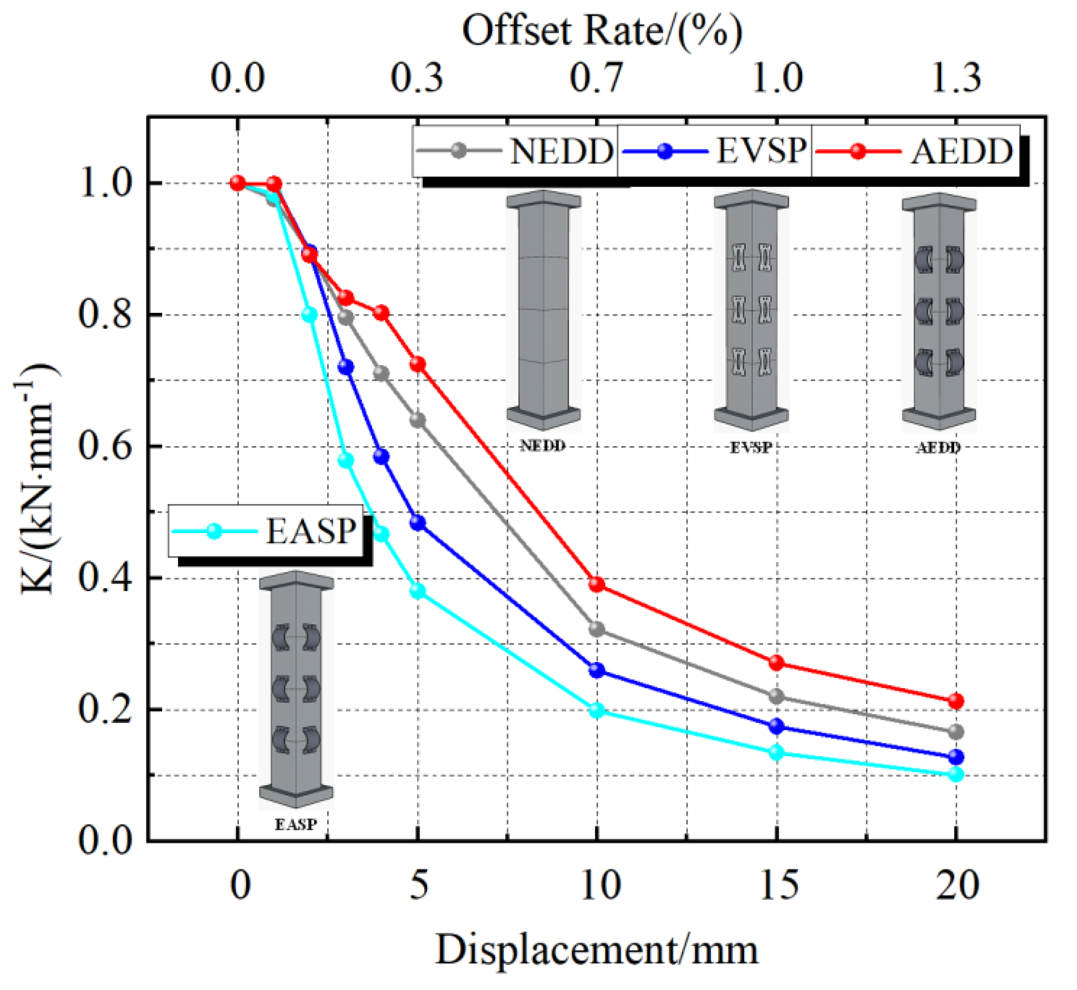
4.5. Stiffness Degradation
5. Multi-Level Energy Consumption and Local Replacement of AEDD
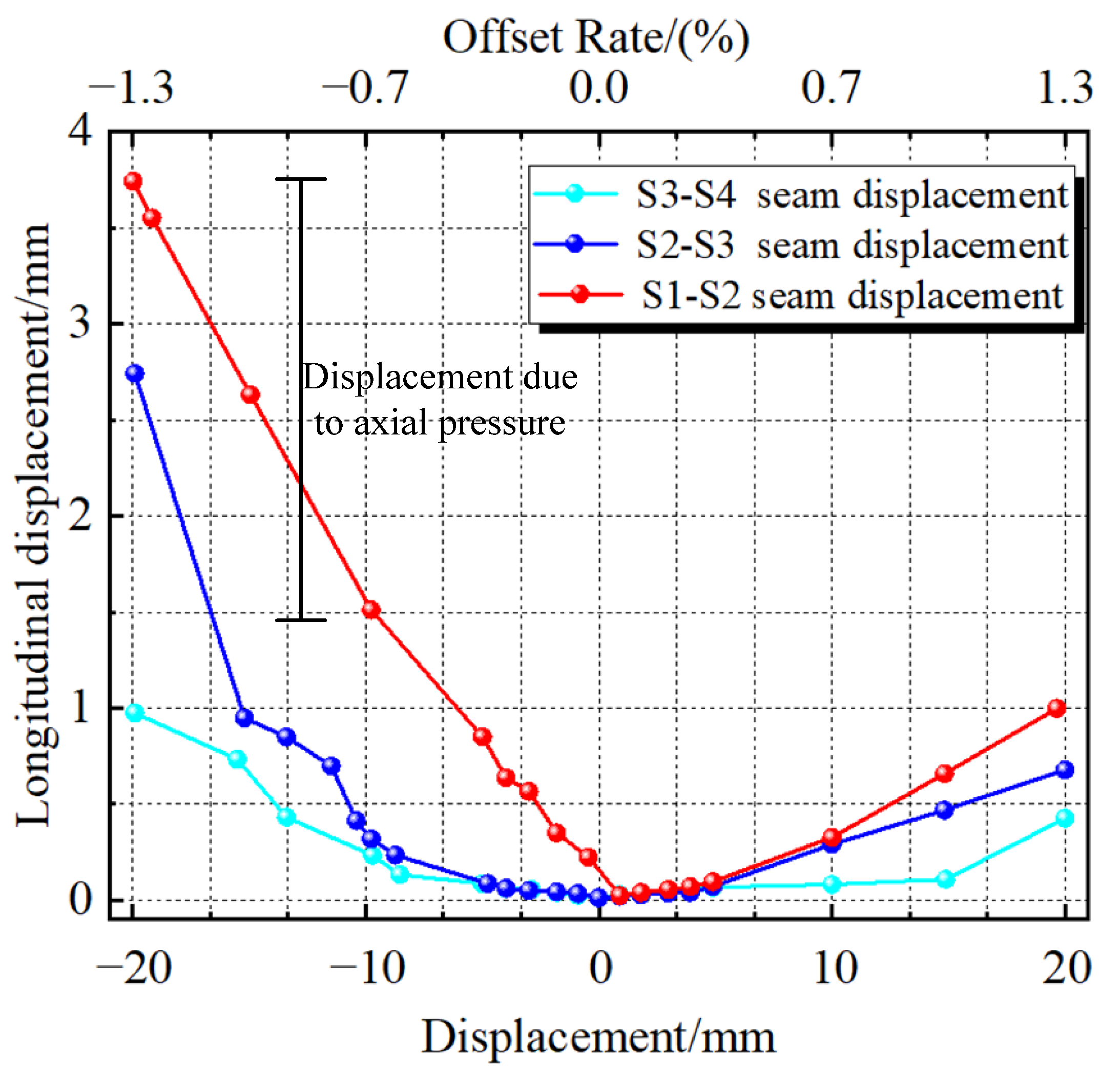
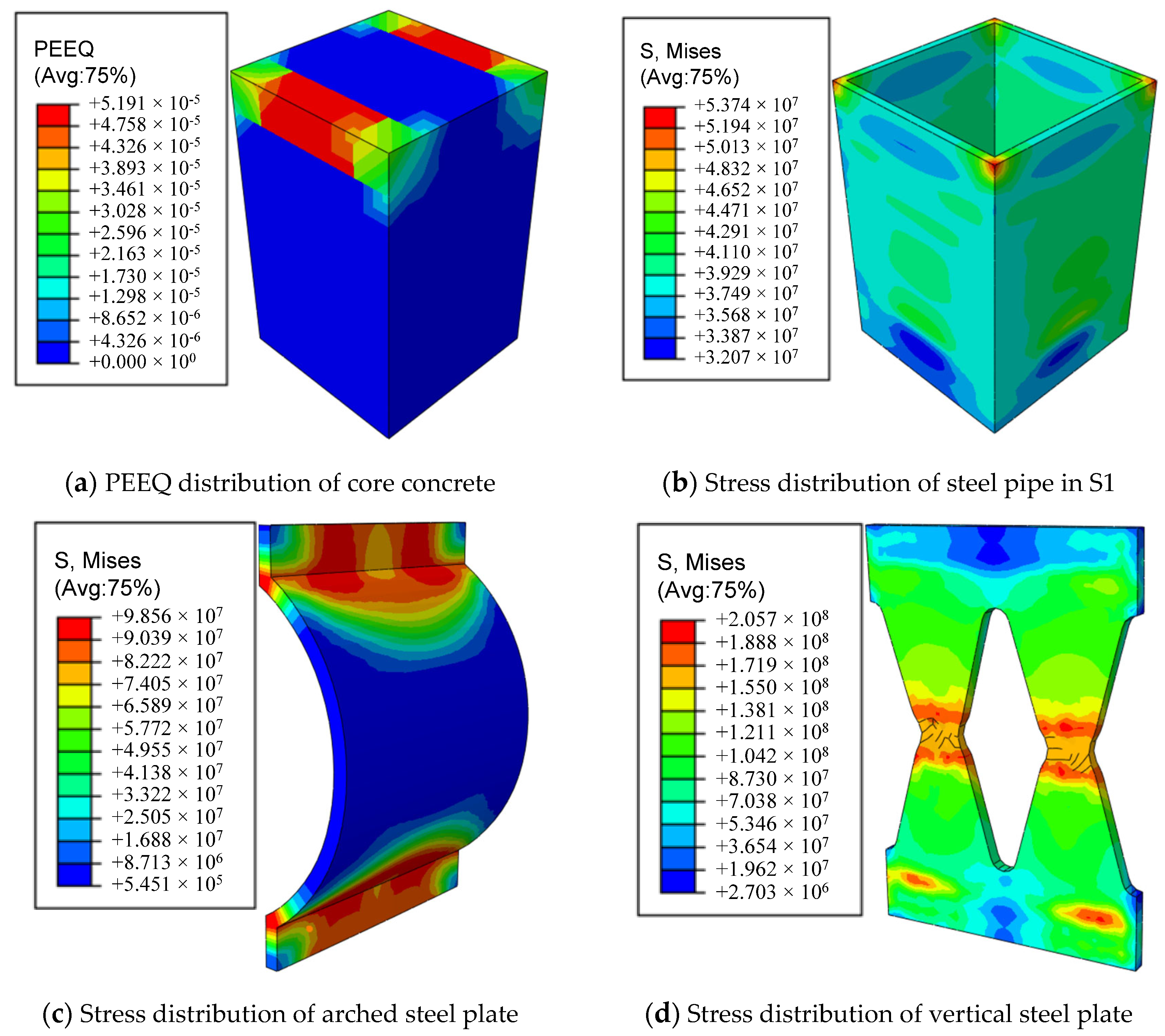
5.1. Multi-Level Energy Consumption
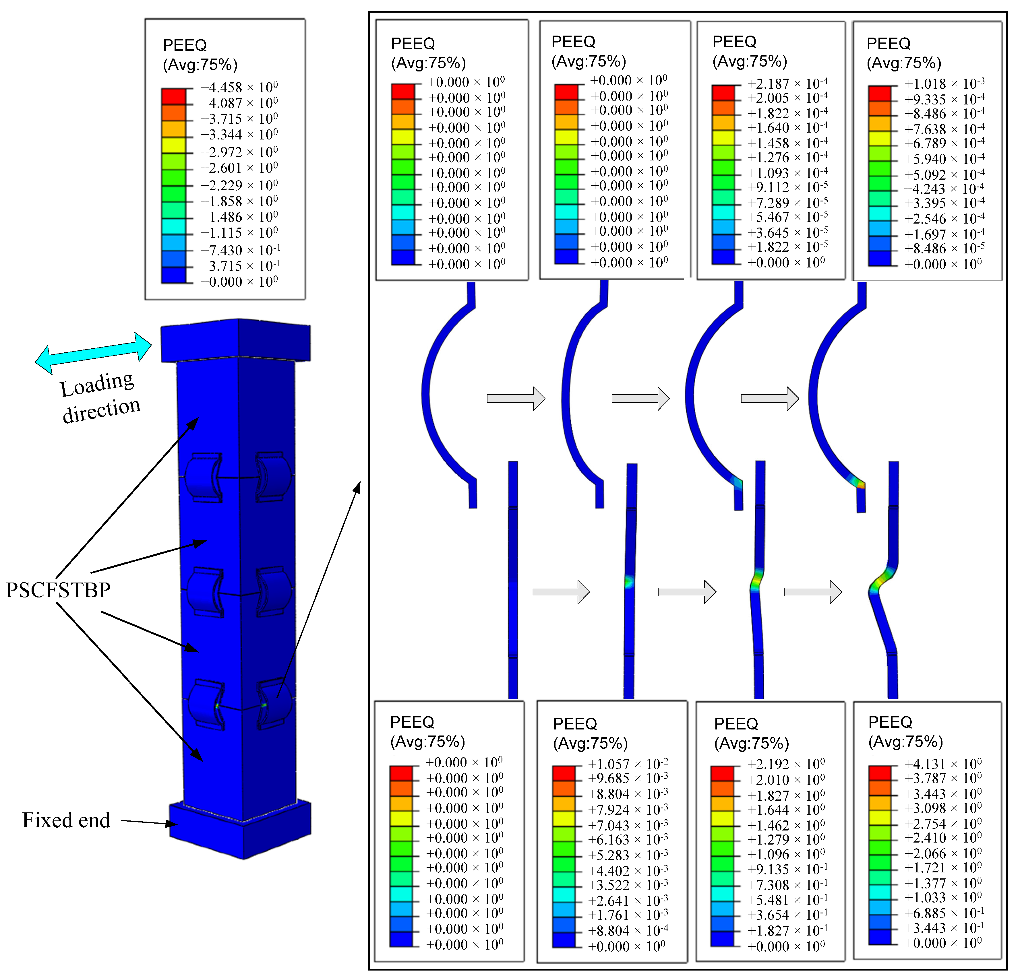
5.2. Partially Replaceable
6. Conclusions
Author Contributions
Funding
Institutional Review Board Statement
Informed Consent Statement
Data Availability Statement
Acknowledgments
Conflicts of Interest
References
- Lan, H. Status quo of research on seismic performance of precast-segmental assembly piers. Highw. Traffic Technol. 2012, 6, 38–42. [Google Scholar]
- Zhao, J.; Liu, X.; Meng, Q.; Li, X. Seismic performance of precast segmental CFST bridge piers with external replaceable energy dissipation devices. J. Southwest Jiaotong Univ. 2021, 55, 22–30. [Google Scholar]
- Wang, J.; Wang, Z.; Gao, Y.; Zhu, J.-Z. Review on aseismic behavior of precast piers: New material, new concept, and new application. Eng. Mech. 2019, 36, 1–23. [Google Scholar]
- Zhang, F.; Hu, Z.; Xue, X. Seismic response of precast assembled piers connected by limit bolts. Traffic Sci. Eng. 2018, 34, 27–34. [Google Scholar]
- Liu, X. Seismic Performance Analysis on the Segmental Concrete Filled Steel Tube Piers with Replaceable Energy Dissipation Devices, d; Qingdao University of Technology: Qingdao, China, 2021. [Google Scholar]
- Du, X.; Zhou, Y.; Han, Q.; Wang, Z. State-of-the-art on rocking piers. Earthq. Eng. Eng. Dyn. 2018, 38, 1–11. [Google Scholar]
- Wang, Z.; Wang, J. Review of seismic performance of prestressed segmental precast and assembled piers. J. Archit. Civ. Eng. 2016, 33, 88–97. [Google Scholar]
- Mander, J.B.; Cheng, C.T. Seismic Resistance of Bridge Piers Based on Damage Avoidance Design; US National Center for Earthquake Engineering Research (NCEER): New York, NY, USA, 1997; pp. 87–99. [Google Scholar]
- Hewes, J.T.; Priestley, M.J.N. Seismic Design and Performance of Precast Concrete Segmental Bridge Columns; University of California: San Diego, CA, USA, 2002. [Google Scholar]
- Chou, C.C.; Chen, Y.C. Cyclic tests of post-tensioned precast CFT segmental bridge columns with unbonded strands. Earth-Quake Eng. Struct. Dyn. 2006, 35, 159–175. [Google Scholar] [CrossRef]
- Jia, J.; Zhao, J.; Zhang, Q.; Qi, L.; Han, Q.; Du, X. Experiment on lateral bearing behavior of post-tensioned segmental CFST bridge pier columns. China J. Highw. Transp. 2017, 30, 236–245. [Google Scholar]
- Jia, J.-F.; Zhao, J.-Y.; Zhang, Q.; Han, Q.; Du, X.; Qi, L. Cyclic Testing on Seismic Behavior of Precast Segmental CFST Bridge Piers with Bolted Connections. China J. Highw. Transp. 2017, 30, 242–249. [Google Scholar]
- Li, J.; Guan, Z. Research progress on bridge seismic design: Target from seismic alleviation to post-earthquake structural resilience. China J. Highw. Transp. 2017, 30, 1–9. [Google Scholar]
- Han, Q.; Jia, Z.; Xu, K.; Zhou, Y.; Du, X. Hysteretic behavior investigation of self-centering double-column rocking piers for seismic resilience. Eng. Struct. 2019, 188, 218–232. [Google Scholar] [CrossRef]
- Wang, Z.; Wang, J.Q.; Tang, Y.C.; Liu, T.-X.; Gao, Y.-F.; Zhang, J. Seismic behavior of precast segmental UHPC bridge columns with replaceable external cover plates and internal dissipaters. Eng. Struct. 2018, 177, 540–555. [Google Scholar] [CrossRef]
- Wang, Z.; Wang, J.Q.; Zhao, G.T.; Zhang, J. Design criterion for the self-centering capacity of precast segmental UHPC bridge columns with unbonded post-tensioning tendons. Eng. Struct. 2019, 200, 87–98. [Google Scholar] [CrossRef]
- Wang, Z.; Wang, J.Q.; Zhu, J.Z.; Zhao, G.; Zhang, J. Energy dissipation and self-centering capacities of posttensioning precast segmental ultra-high performance concrete bridge columns. Struct. Concr. 2020, 21, 45–55. [Google Scholar] [CrossRef]
- Moustafa, A.; El Gawady, M.A. Shaking table testing of segmental hollow-core FRP-concrete-steel bridge columns. J. Bridge Eng. 2018, 23, 40–52. [Google Scholar] [CrossRef]
- Wang, C.; Qu, Z.; Shen, Y.; Ping, B.; Xie, J. Cyclic Testing on Seismic Behavior of Segmental Assembled CFST Bridge Pier with External Replaceable. Metals 2022, 12, 1156. [Google Scholar] [CrossRef]
- Wang, C.Q.; Qu, Z.; Shen, Y.; Jiang, J.; Yin, C.; Zong, Y. Numerical Investigation of the Performance of Segmental CFST Piers with External Energy Dissipators under Lateral Cyclic Loadings. Materials 2022, 15, 6993. [Google Scholar] [CrossRef]
- Nikbakht, E.; Rashid, K.; Hejazi, F.; Osman, S.A. A numerical study on seismic response of self-centring precast segmental columns at different post-tensioning forces. Lat. Am. J. Solids Struct 2014, 11, 864–883. [Google Scholar] [CrossRef] [Green Version]
- Han, L.H. Concrete-Filled Steel Tube Structure—Theory and Practice, 2nd ed.; Science Press: Beijing, China, 2007. [Google Scholar]
- Nie, J.; Wang, Y. Comparison study of constitutive model of concrete in ABAQUS for static analysis of structures. Eng. Mech. 2013, 30, 59–67. [Google Scholar]
- Ministry of Commerce, People’s Republic of China. GB50010-2010; Code for Design of Concrete Structures; MOHURD: Beijing, China, 2010. [Google Scholar]
- OU, Y.C.; Chiewanichakorn, M. Seismic performance of segmental precast unbonded posttensioned concrete bridge columns. J. Struct. Eng. 2007, 133, 1636–1647. [Google Scholar] [CrossRef]
- Xu, Y.; Wang, X.; Liu, G.; Zhu, A. The proposal of concrete structure theory development and code amendment. J. Build. Struct. 2007, 28, 1–6. [Google Scholar]
- Luong, C.N.; Yang, C.; Ezzeldin, M. Genetic Programming–Based Drift Ratio Limit Models for Segmental Posttensioned Precast Concrete Piers. ASCE J. Struct. Eng. 2023, 28, 04022149. [Google Scholar] [CrossRef]
- Du, Q.; Zhang, S.; Qing, L. Analysis and simulation of force performance of prefabricated segmental assembled bridge piers. J. Chongqing Jiaotong Univ. 2020, 39, 73–80. [Google Scholar]
- Rong, B.; Li, H.; Zhang, R. Experimental and Numerical Investigations on Seismic Performance of CFST Frame with External Diaphragm Joint. ASCE J. Struct. Eng. 2021, 147, 04021182. [Google Scholar] [CrossRef]
- Yin, F.; Xue, S.-D.; Cao, W.-L.; Dong, H.-Y.; Wu, H.-P. Experimental and Analytical Study of Seismic Behavior of Special-Shaped Multicell Composite Concrete-Filled Steel Tube Columns. ASCE J. Struct. Eng. 2020, 146, 04019170. [Google Scholar] [CrossRef]
- Bao, L.; Song, J.; Yu, L. Research on effect of prestress degree on seismic performance of segmental assembly piers. J. Dalian Univ. Technol. 2019, 59, 302–309. [Google Scholar]
- Shi, Y.; Wang, M.; Wang, Y. Experimental study of structural steel constitutive relationship under cyclic loading. J. Build. Mater. 2012, 15, 293–300. [Google Scholar]
- Zhang, Y.; Wu, G.; Sun, Z. Sun, Z. Teng, G. Analysis of seismic performance of a hybrid precast bridge pier system. J. Chang. Univ. (Nat. Sci. Ed.) 2019, 39, 70–80. [Google Scholar]
- Gong, X.-T.; Yang, F. Deformation behavior of conical ring with outer steps for cold ring rolling. Forg. Stamp. Technol. 2012, 37, 58–67. [Google Scholar]
- Bao, L.; Wang, L.; Mei, R.; Wang, K.; Pang, H. Analysis on different finite element software solutions and influencing factors in cylinder compression process. Forg. Stamp. Technol. 2022, 47, 47–56. [Google Scholar]


| Material | Model | The Yield Strength fy/MPa | Ultimate Strength fu/MPa | Compressive Strength fc/MPa | Modulus of Elasticity Es/(×104 MPa) |
|---|---|---|---|---|---|
| Steel | Q235 | 276.6 | 474.1 | - | 20.4 |
| Q345 | 381.7 | 580.2 | - | 20.8 | |
| Concrete | C40 | - | - | 42.6 | 3.26 |
| 30 | 0.1 | 1.16 | 0.6667 | 0.0005 |
| Compare the Item | Lateral Bearing Capacity/(kN) | Equivalent Stiffness/(kN·mm−1) | Energy Dissipation/(kN·m) |
|---|---|---|---|
| The test results | 74.1 | 1.1 | 15.3 |
| The simulation results | 67.6 | 1.0 | 16.2 |
| Difference rate | 8.7% | 9.1% | 5.9% |
| Specimen | The Yield Strength/kN | The Yield Displacement/mm | Peak Bearing Capacity/kN | Peak Displacement/mm | Ductility Coefficient |
|---|---|---|---|---|---|
| NEDD | 38.32 | 9.72 | 40.02 | 19.03 | 1.96 |
| EASP | 40.50 | 9.80 | 42.57 | 19.93 | 2.03 |
| EVSP | 48.39 | 9.80 | 48.65 | 19.95 | 2.04 |
| AEDD | 53.92 | 10.00 | 54.44 | 19.65 | 1.97 |
Disclaimer/Publisher’s Note: The statements, opinions and data contained in all publications are solely those of the individual author(s) and contributor(s) and not of MDPI and/or the editor(s). MDPI and/or the editor(s) disclaim responsibility for any injury to people or property resulting from any ideas, methods, instructions or products referred to in the content. |
© 2022 by the authors. Licensee MDPI, Basel, Switzerland. This article is an open access article distributed under the terms and conditions of the Creative Commons Attribution (CC BY) license (https://creativecommons.org/licenses/by/4.0/).
Share and Cite
Wang, C.; Zong, Y.; Zou, Y.; Shen, Y.; Jiang, J.; Yin, C. Quasistatic Analysis of Precast Segmental Concrete-Filled Steel-Tube Bridge Pier with External Arched Energy Dissipation Device. Materials 2023, 16, 340. https://doi.org/10.3390/ma16010340
Wang C, Zong Y, Zou Y, Shen Y, Jiang J, Yin C. Quasistatic Analysis of Precast Segmental Concrete-Filled Steel-Tube Bridge Pier with External Arched Energy Dissipation Device. Materials. 2023; 16(1):340. https://doi.org/10.3390/ma16010340
Chicago/Turabian StyleWang, Chengquan, Yanwei Zong, Yun Zou, Yonggang Shen, Jiqing Jiang, and Chongli Yin. 2023. "Quasistatic Analysis of Precast Segmental Concrete-Filled Steel-Tube Bridge Pier with External Arched Energy Dissipation Device" Materials 16, no. 1: 340. https://doi.org/10.3390/ma16010340