
Effect of Heat Treatment on Tensile Properties and Microstructure of Co-Free, Low Ni-10 Mo-1.2 Ti Maraging Steel


Abstract
:1. Introduction
2. Materials and Methods
2.1. Production and Material
2.2. Thermo-Calc Studies
2.3. Differential Scanning Calorimetry (DSC)
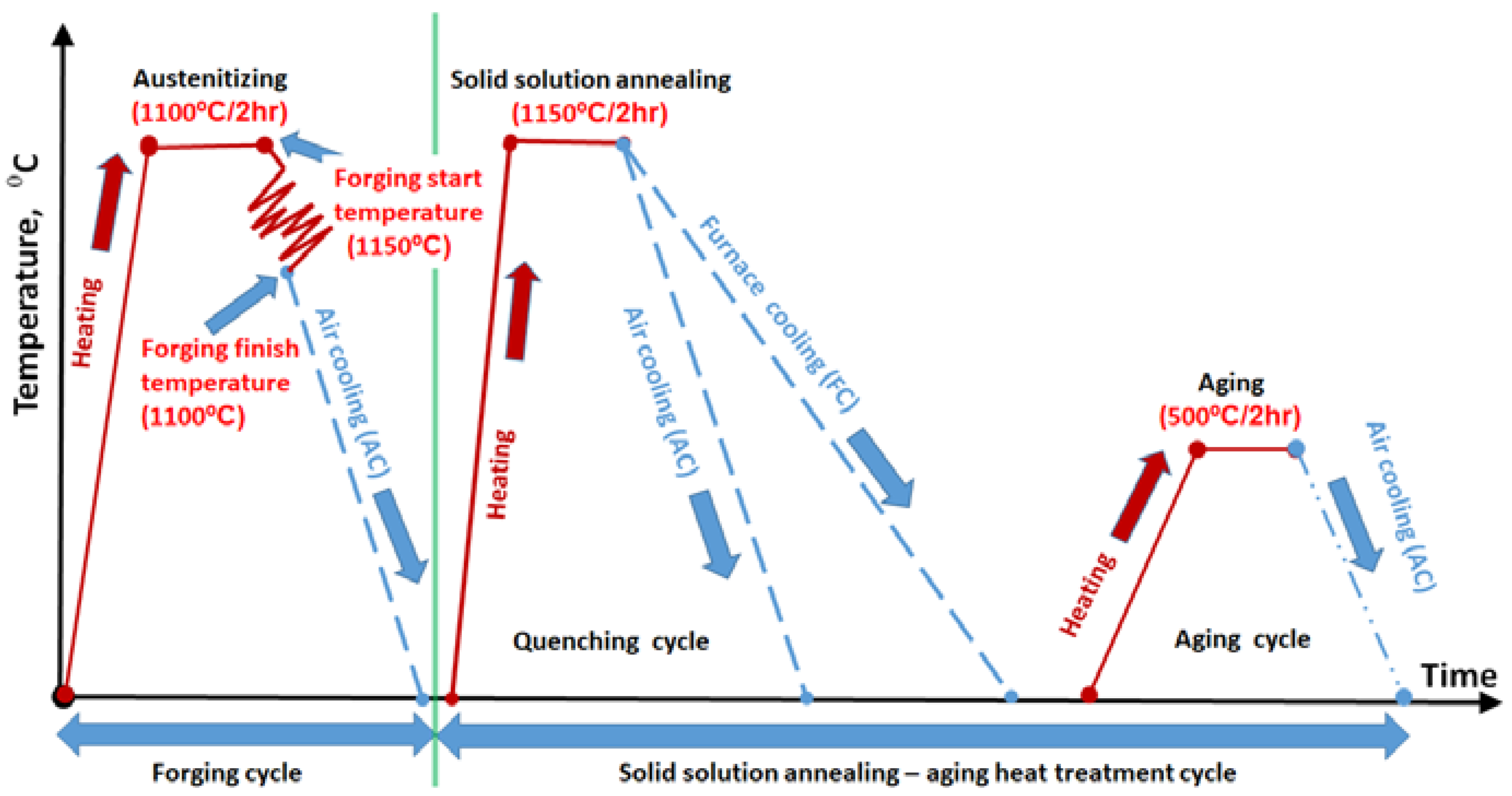
2.4. Solution Treatment and Age Hardening
2.5. Mechanical Properties
2.6. Microstructural Evaluation
3. Results and Discussion
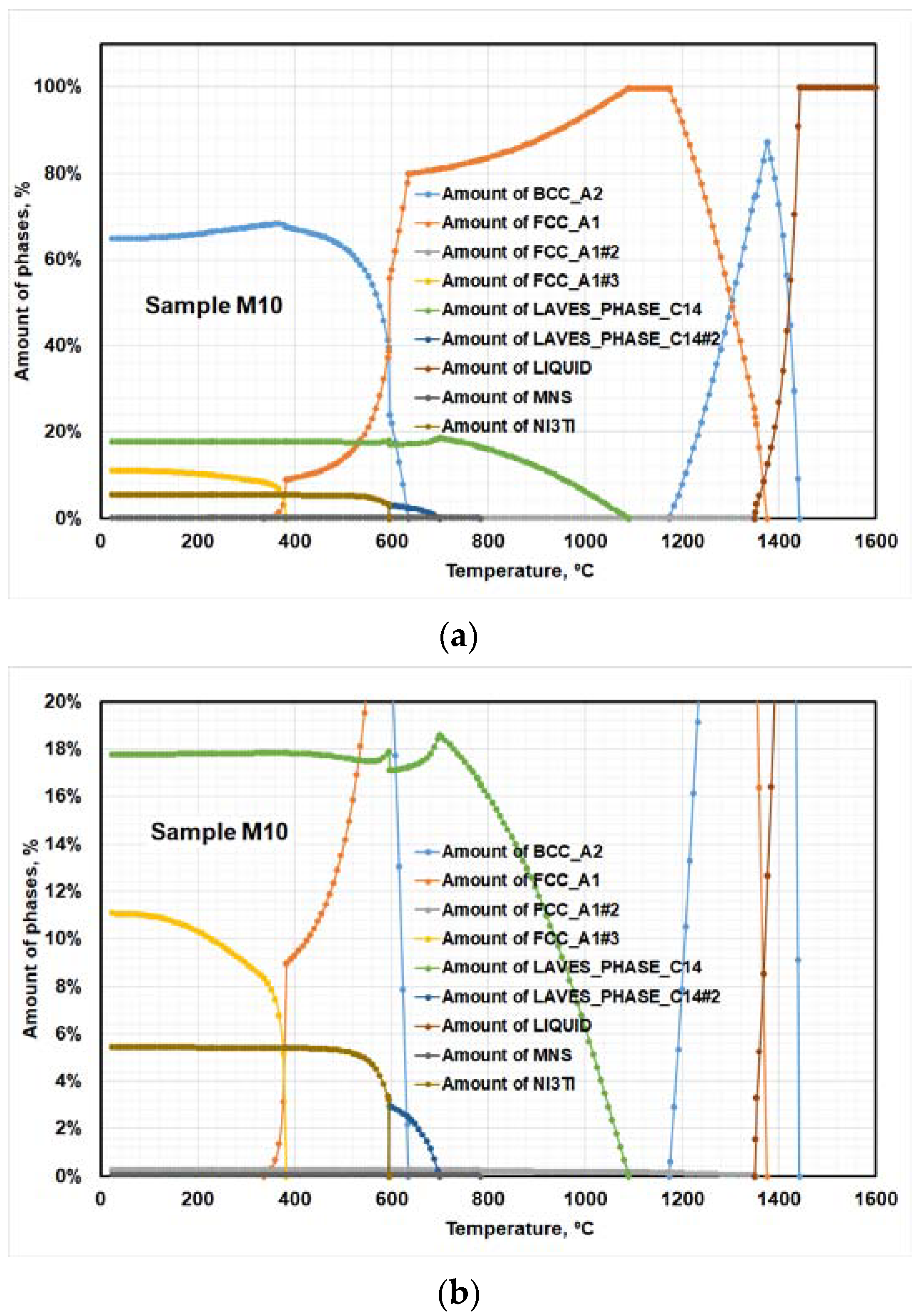
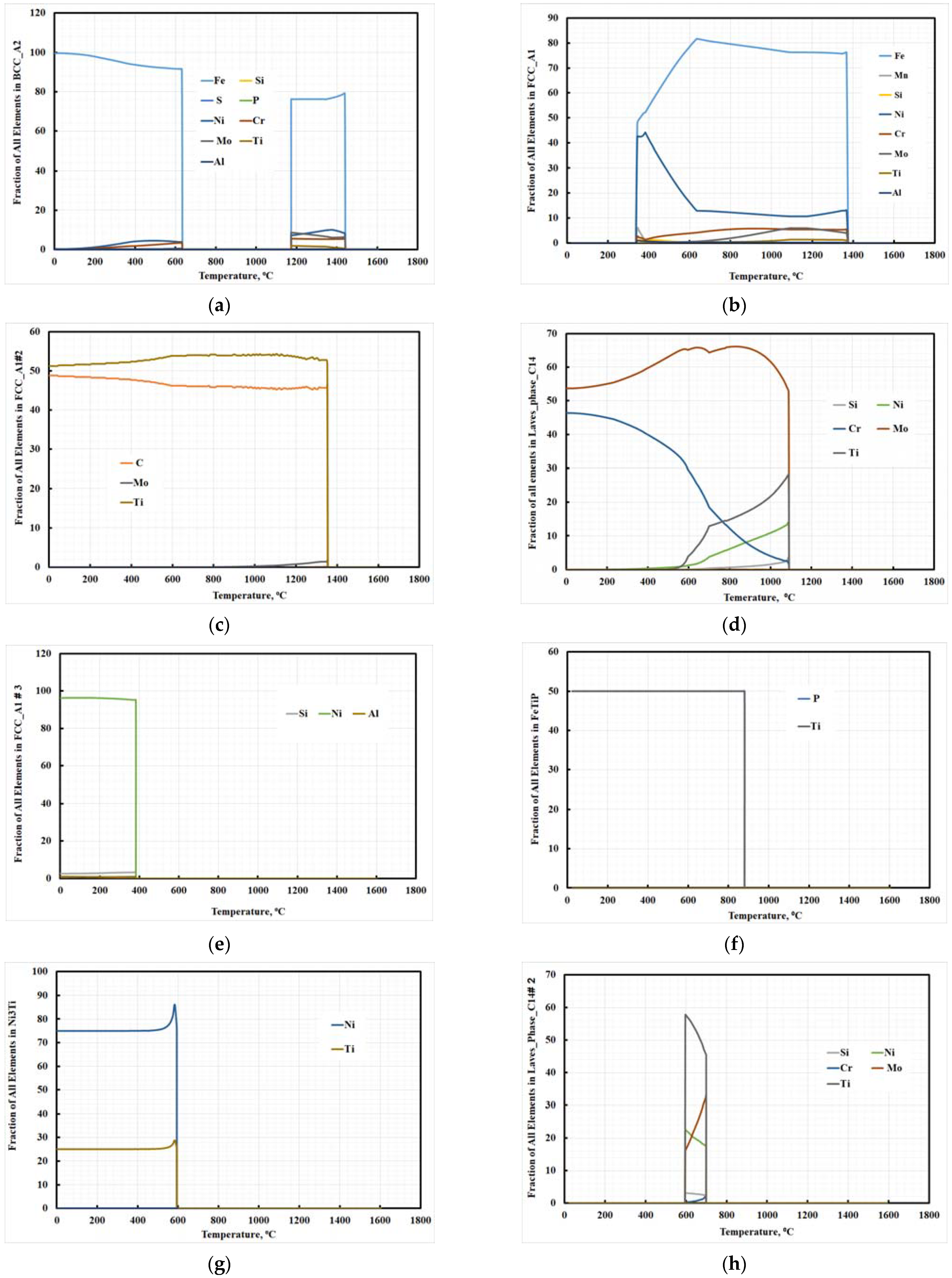
3.1. Thermo-Calc Study
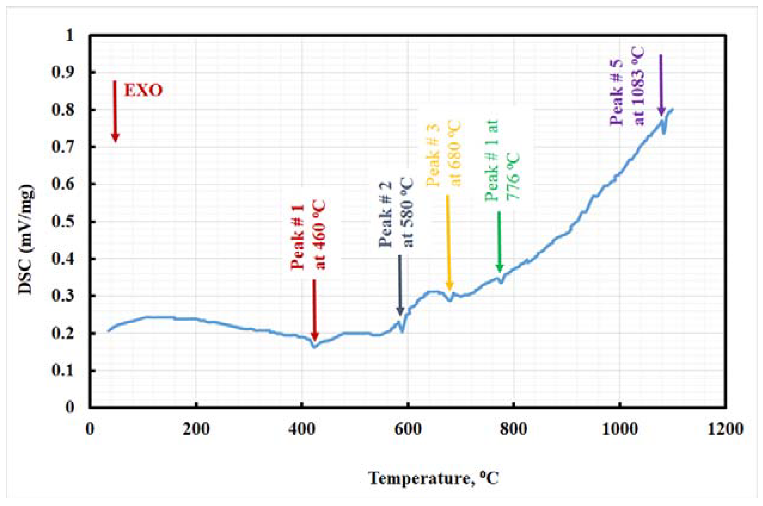
3.2. DSC Analysis
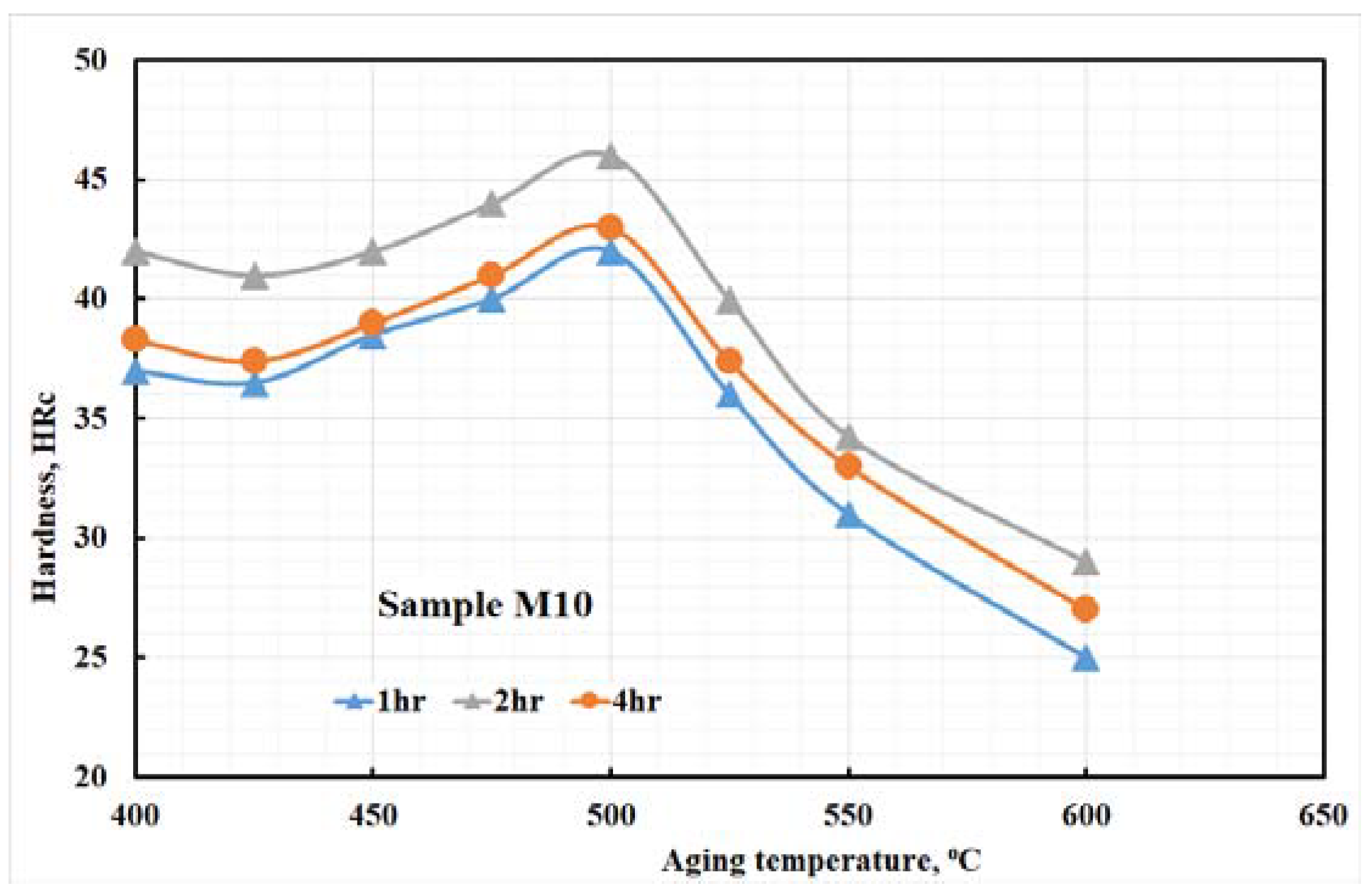
3.3. Aging Treatment
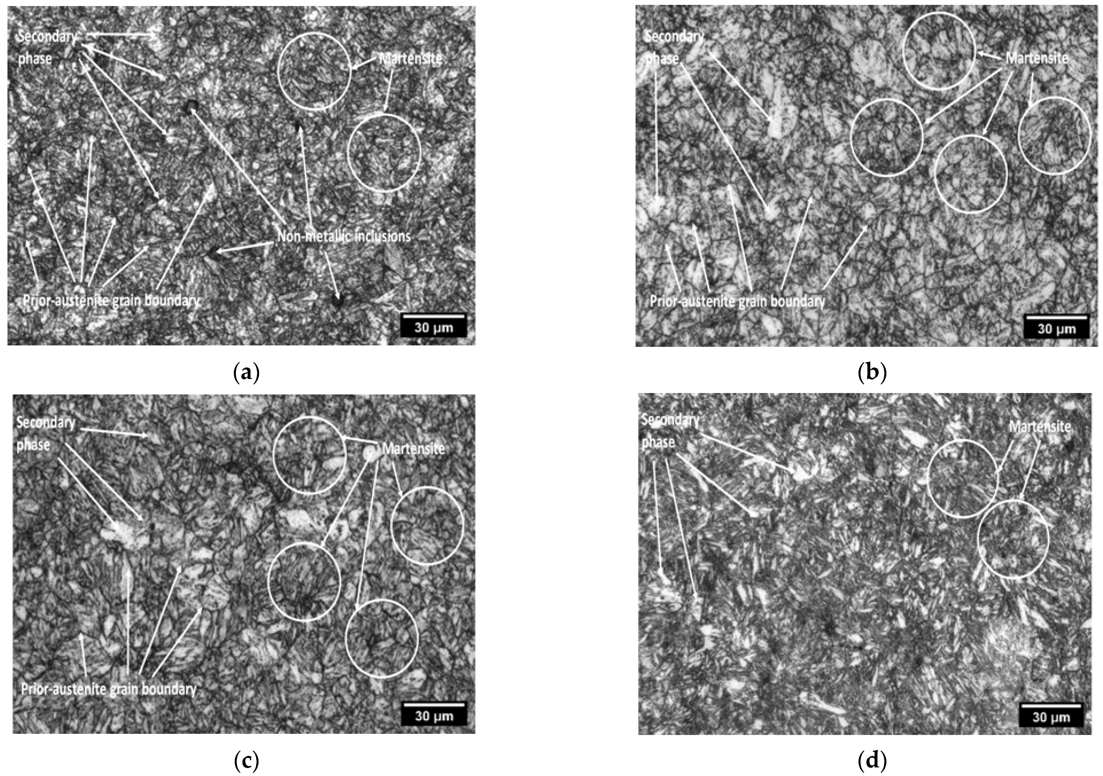
3.4. Microstructural Analysis
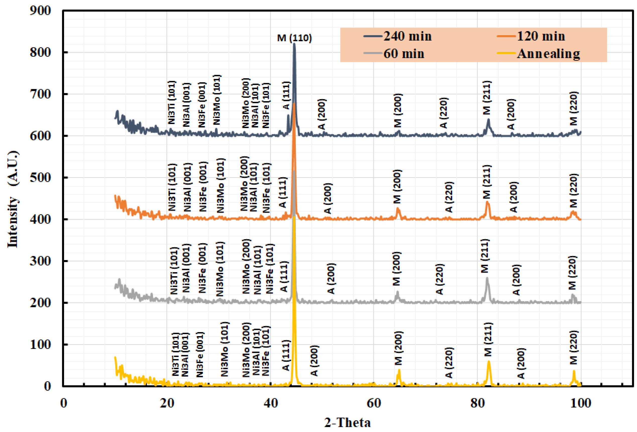
3.5. XRD Analysis
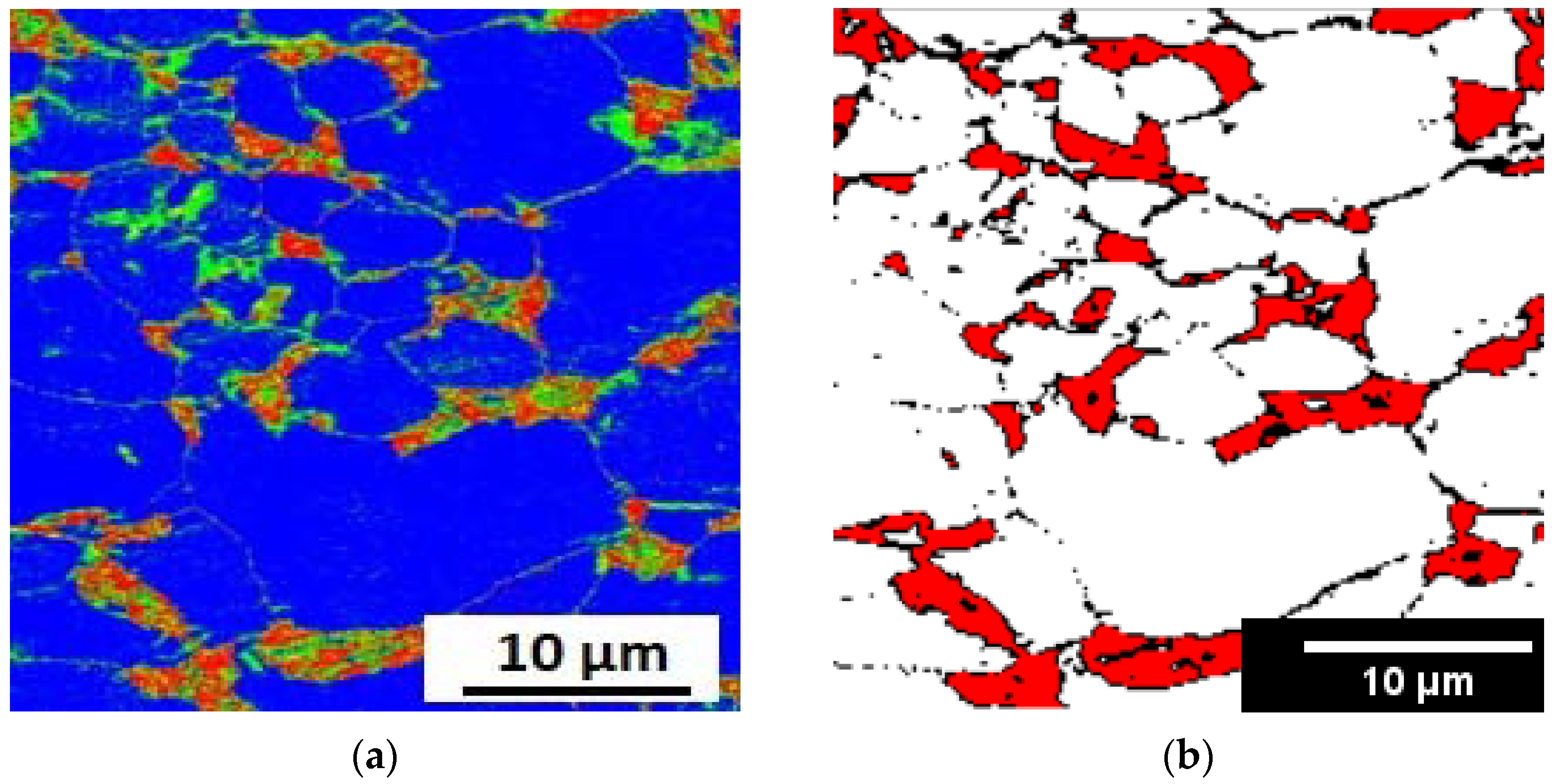
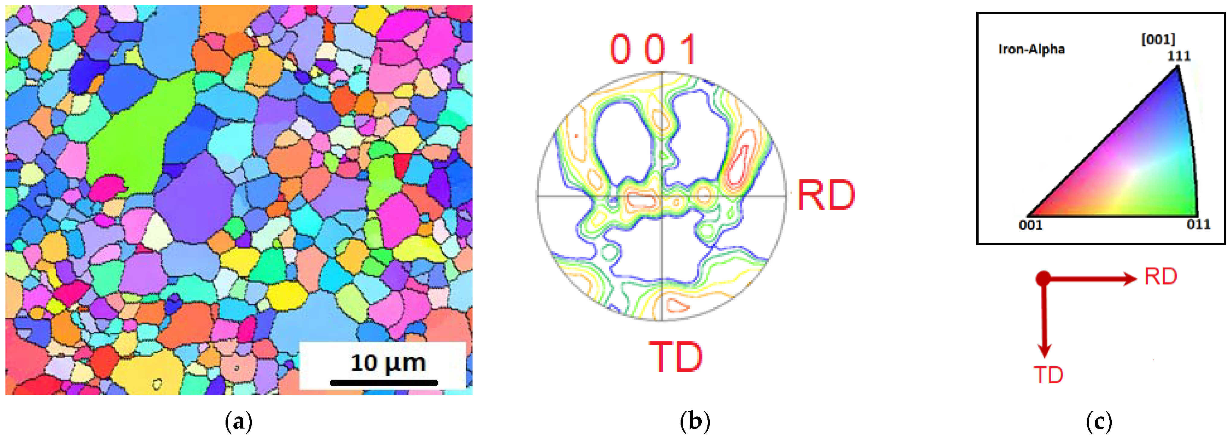
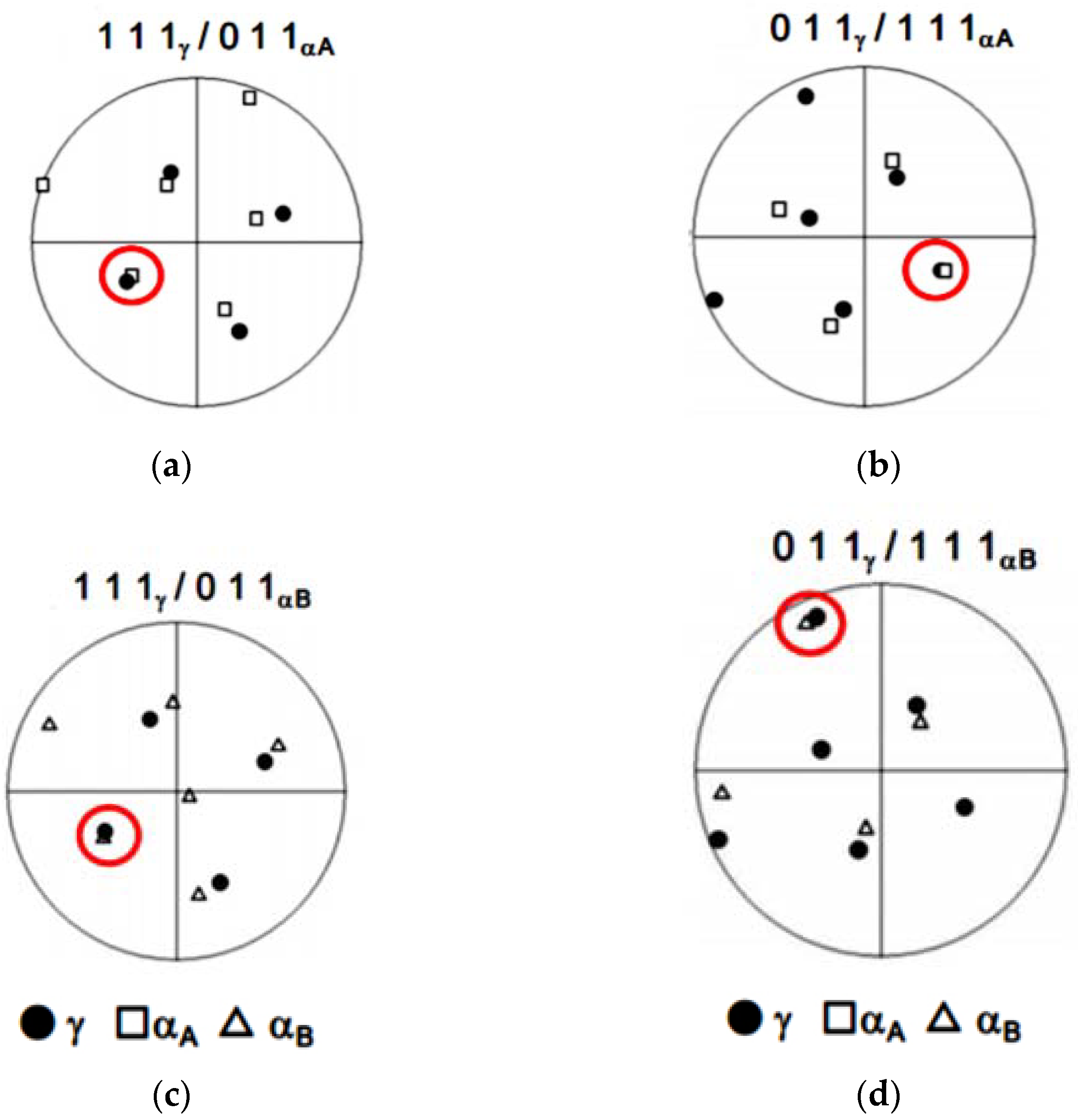
3.6. EBSD Analysis
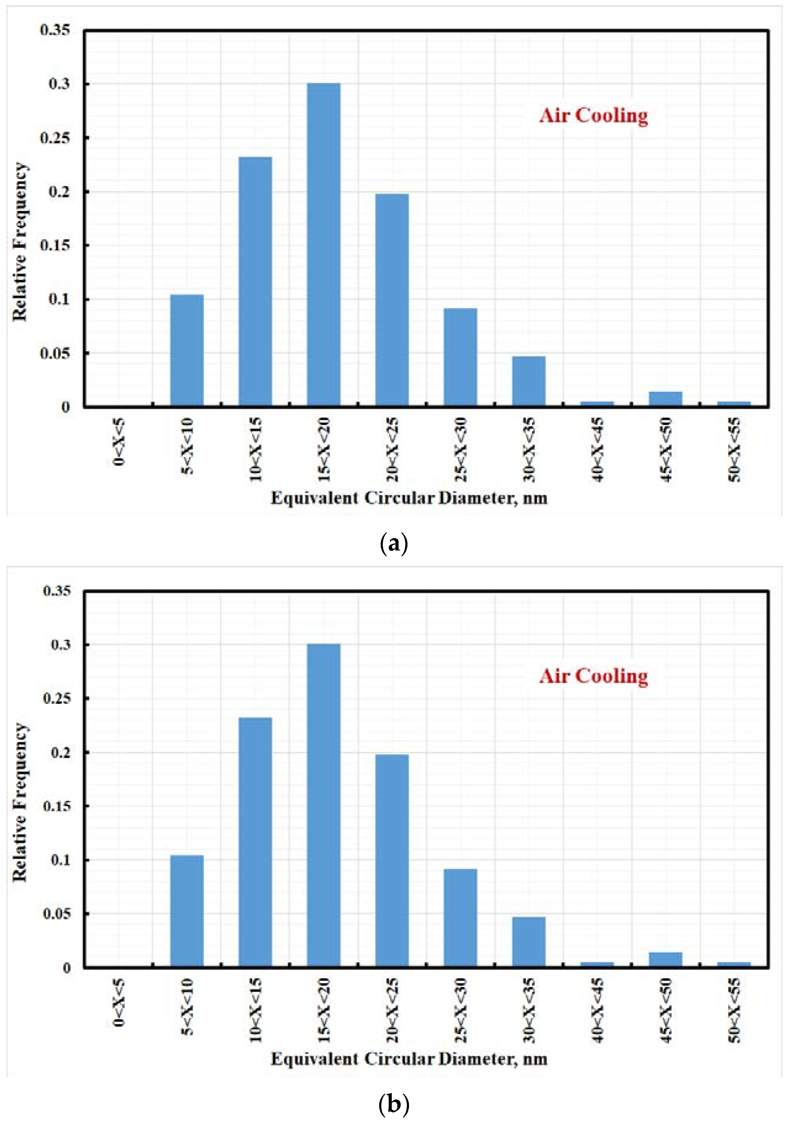
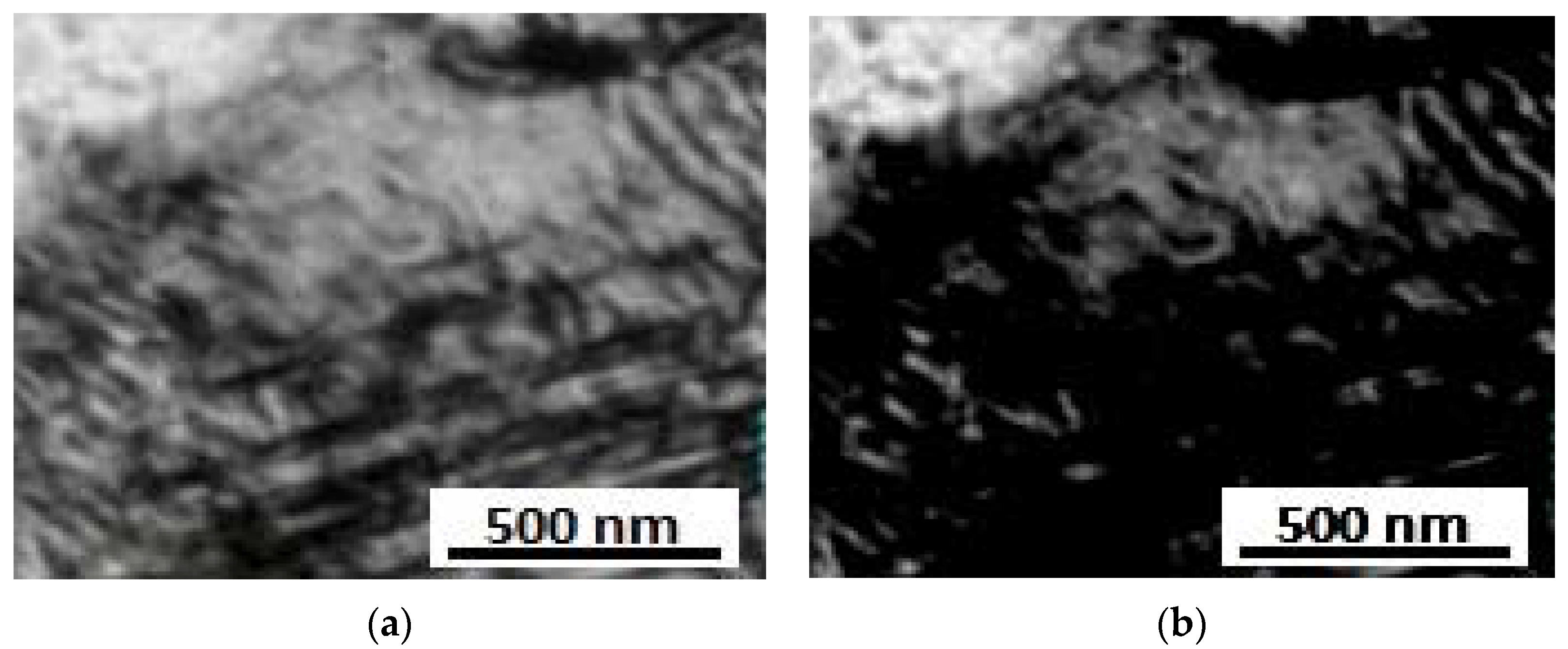
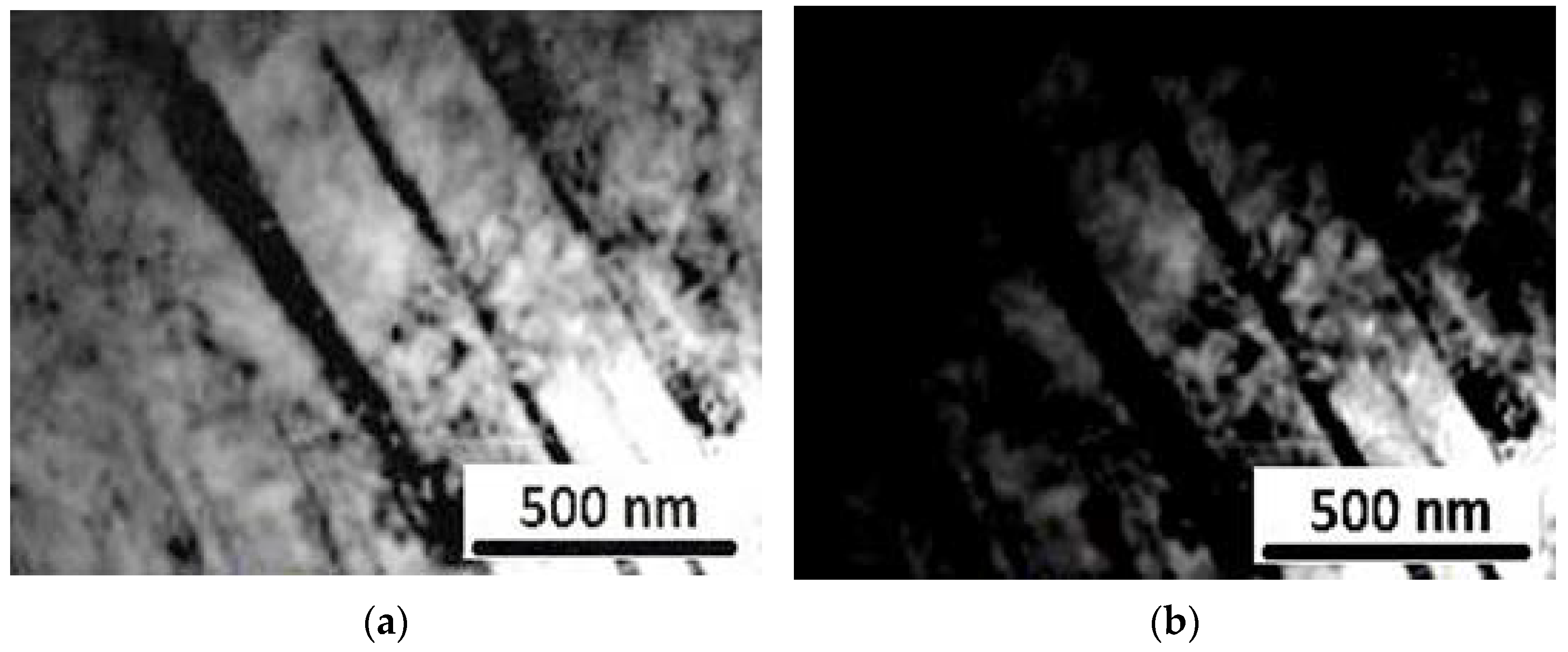
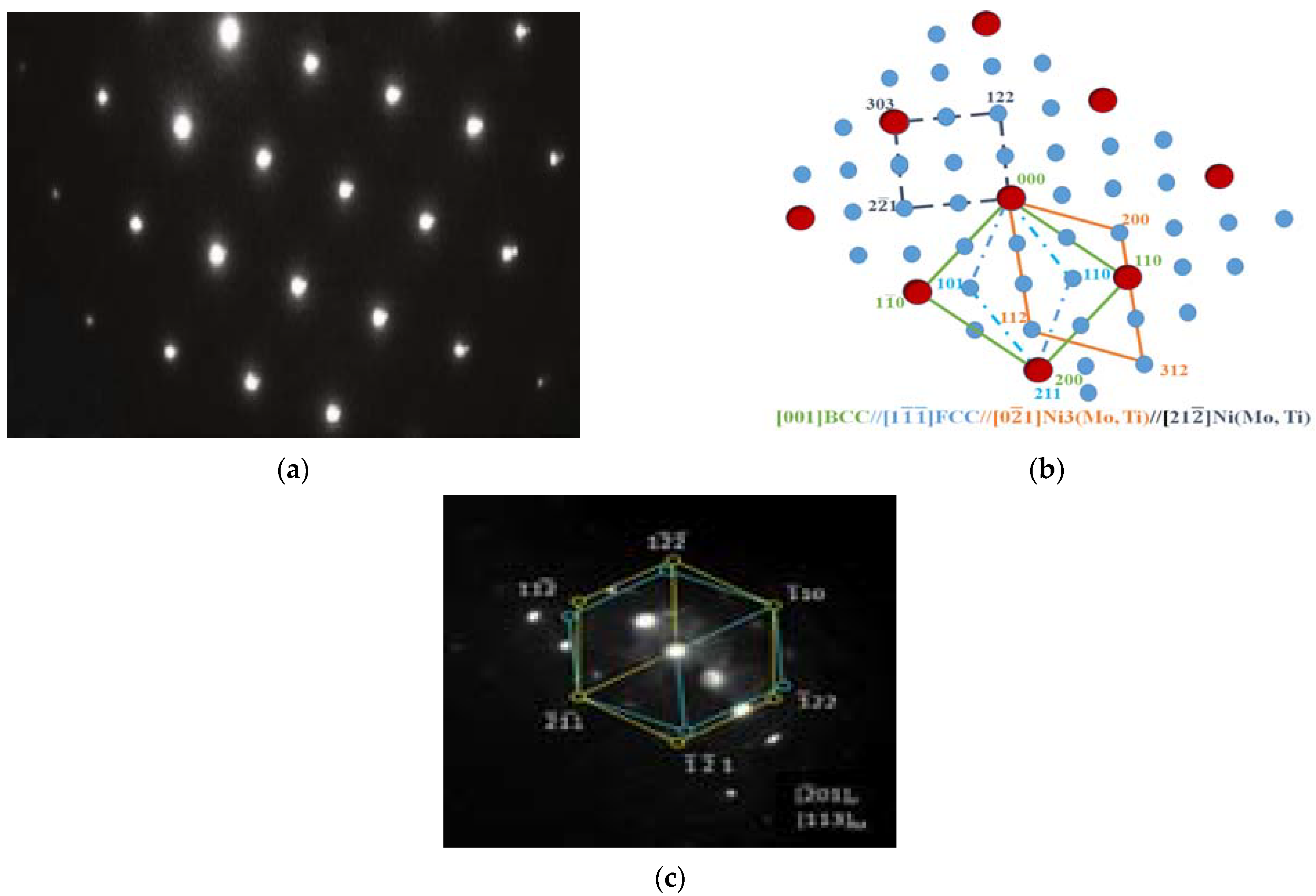
3.7. TEM Analysis
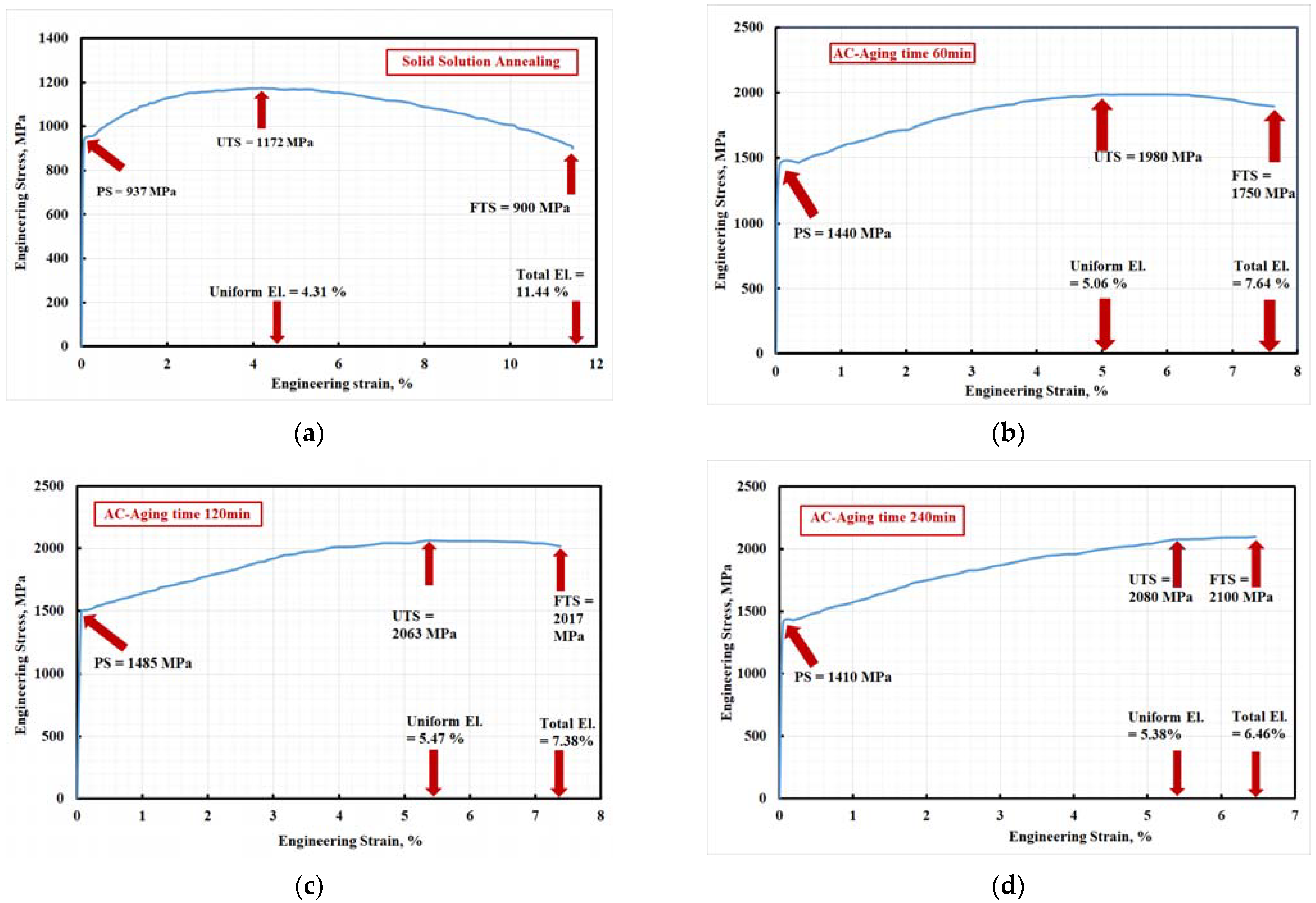
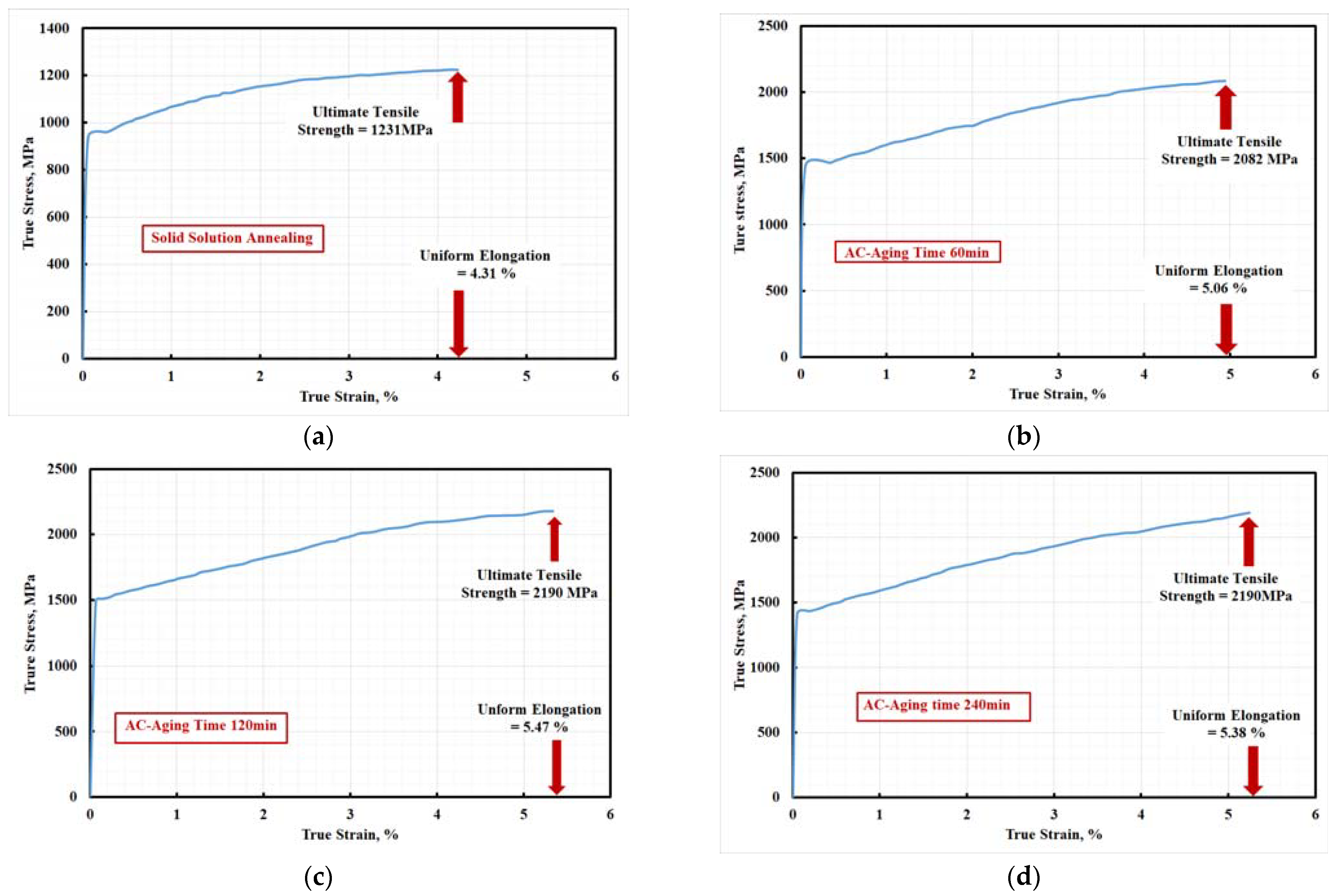
3.8. Effect of Aging Time on Tensile Properties
4. Conclusions
- The low carbon content of the investigated steel leads to very low or no carbide precipitate. High molybdenum contents encouraged lava-phase precipitate with chemical composition formula MoCr and enforced the investigated steel to precipitate η(Ni3Ti).
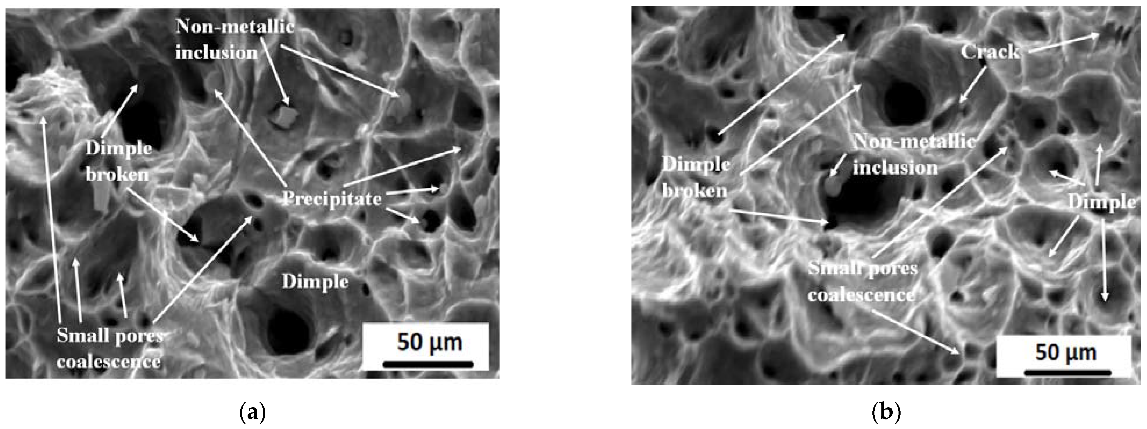
- The microstructure of aged steel specimens consists of (i) high-alloyed martensite phase, (ii) nickel-rich phase, (iii) low-alloyed retained-austenite phase, (iv) intermetallic compounds, (v) and lavas-phase (MoCr). The presence of this microstructure enhances the tensile properties by precipitation strengthening and TRIP phenomenon.
- TEM and EBSD studies emphasized that the produced steel has high dislocation density with nano-sized precipitate with an average size ~19 ± 1 nm.
- EBSD studies revealed that the fine austenite (γ) grains were distributed in a ferrite (α-martensite) matrix. The retained γ phases often appeared along the grain boundaries in the α-martensite matrix. Many of the fine γ grains were oriented along the Z-direction, forming a {001} texture of the retained γ phase.
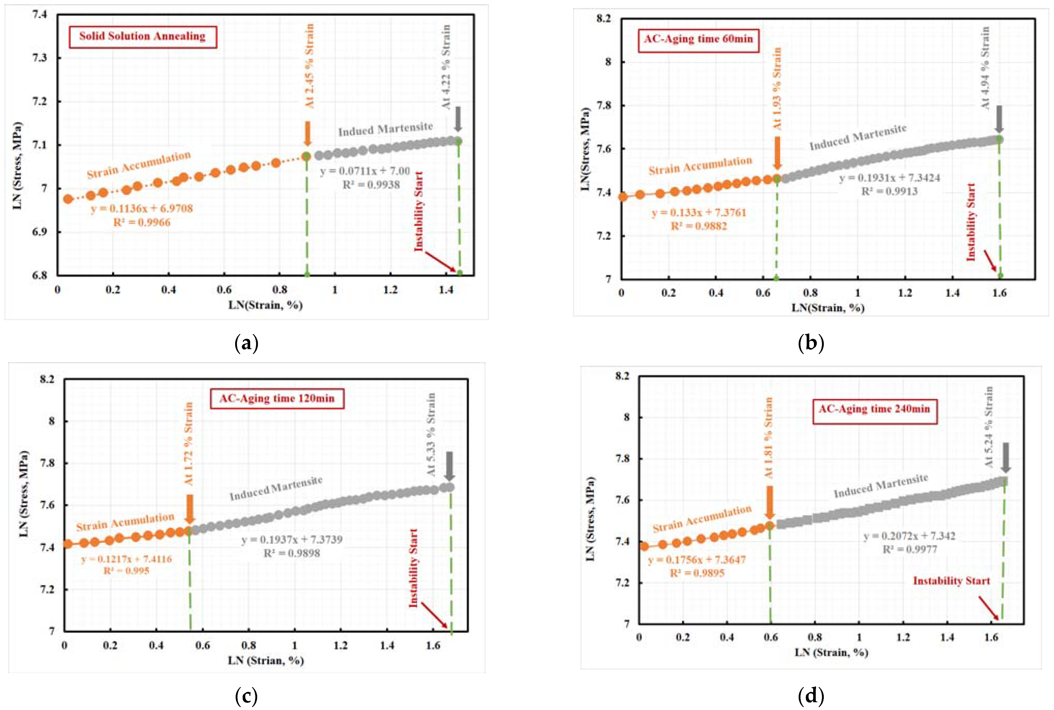
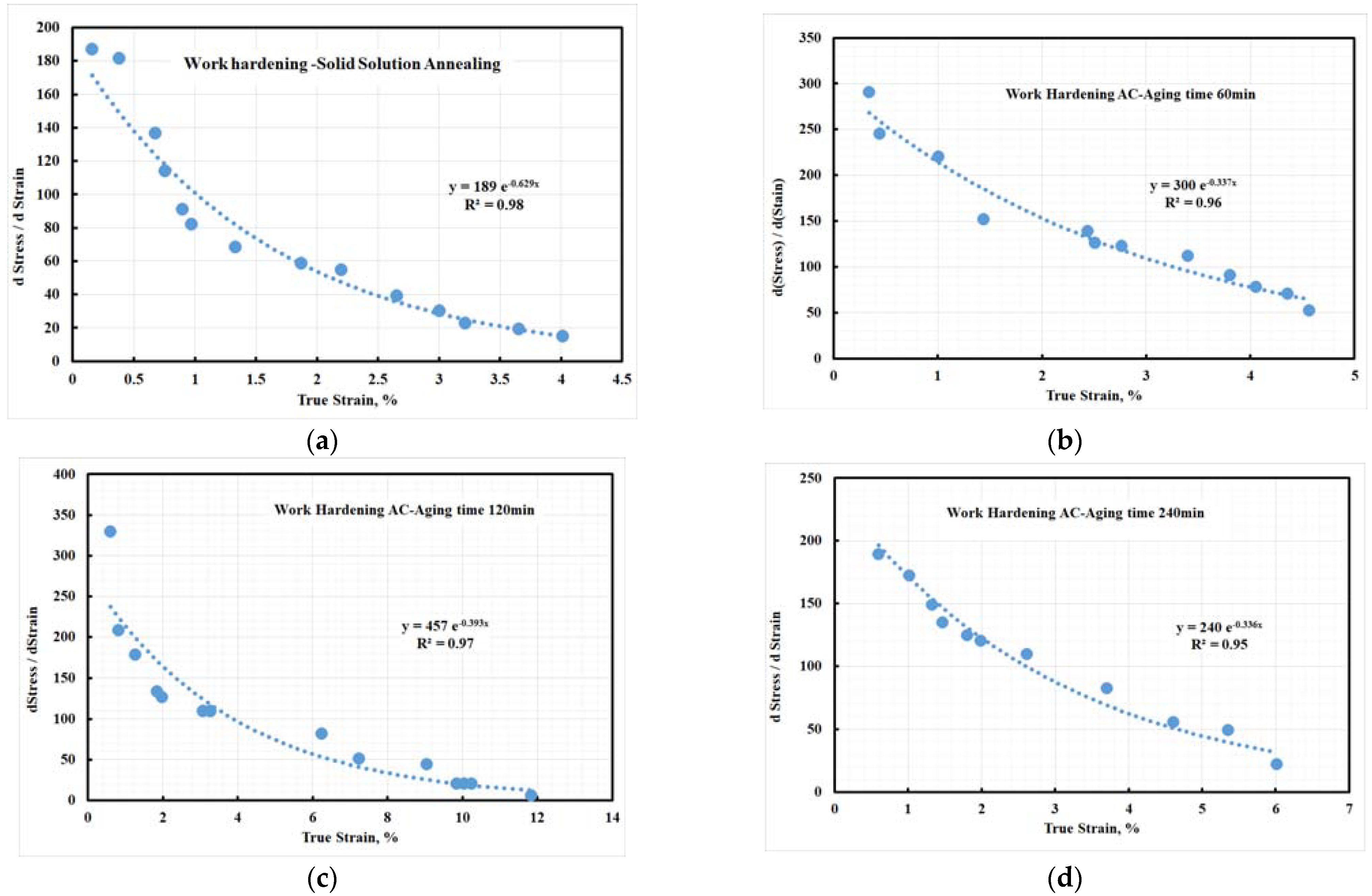
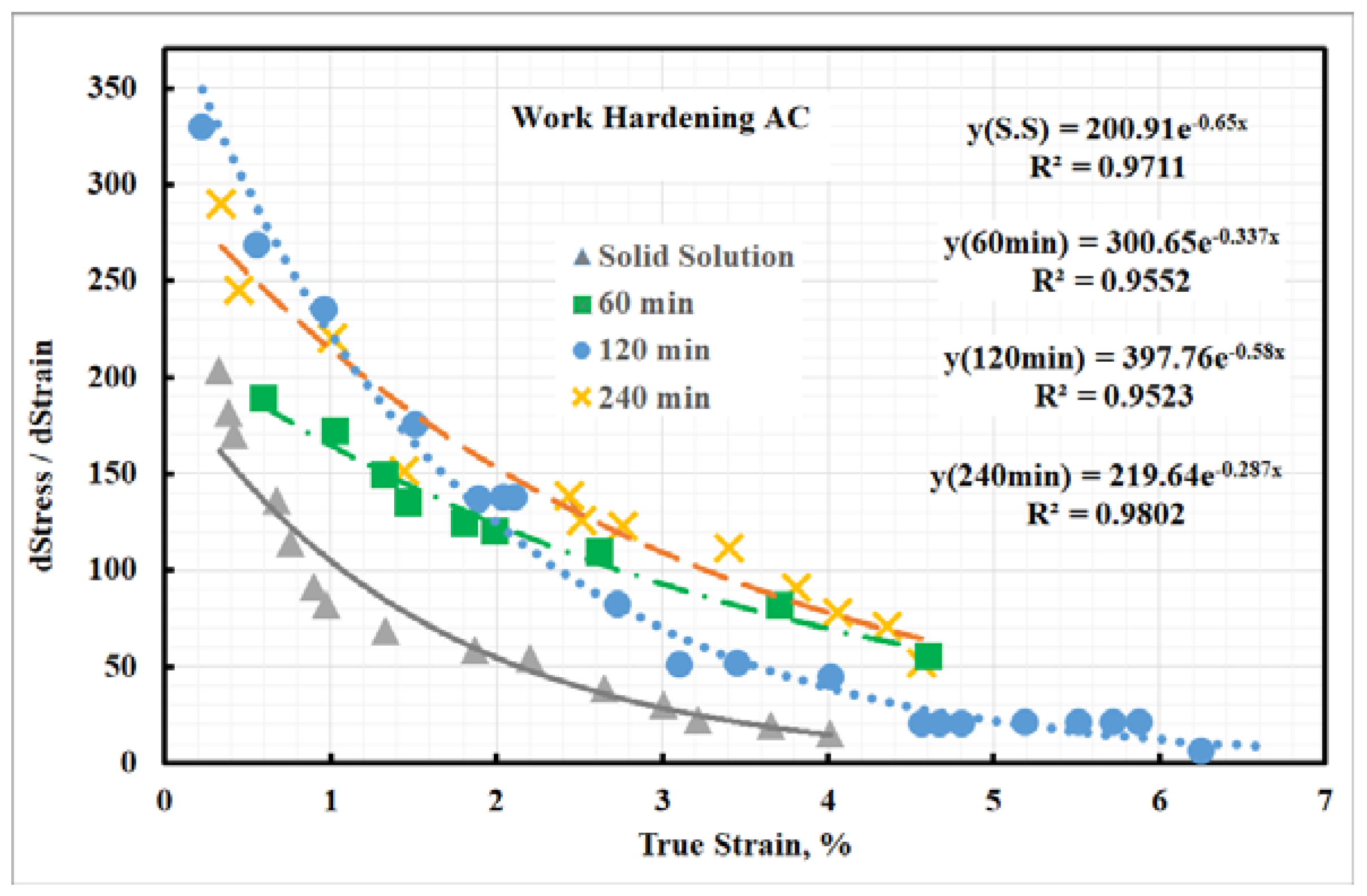
- Calculation of the strain hardening exponent (n-value) shows that investigated steel (passing two stages) and its n-value are comparable with the n-value of TRIP steel. Aging the steel specimens at 500 °C and 120 min shows a high work-hardening rate compared with other aged steel specimens.
Author Contributions
Funding
Data Availability Statement
Conflicts of Interest
References
- ASM International. ASM Handbook Volume 1 Properties and Selection: Irons, Steels and High-Performance Alloys; ASM International: Cleveland, OH, USA, 1990; pp. 1303–1408. ISBN 978-0-87170-377-4. [Google Scholar]
- Yasa, E.; Kempen, K.; Kruth, J.-P. Microstructure and mechanical properties of maraging steel 300 after selective laser melting. In Proceedings of the Solid Freeform Fabrication Symposium Proceedings, Austin, TX, USA, 9–11 August 2010; pp. 383–396. [Google Scholar]
- Fortunato, A.; Lulaj, A.; Melkote, S.; Liverani, E.; Ascari, A.; Umbrello, D. Milling of maraging steel components produced by selective laser melting. Int. J. Adv. Manuf. Technol. 2018, 94, 1895–1902. [Google Scholar] [CrossRef]
- Miki, Y.; Kitaoka, H.; Sakuraya, T.; Fujii, T. Mechanism for Separating Inclusions from Molten Steel Stirred with a Rotating Electromagnetic Field. ISIJ Int. 1992, 32, 142–149. [Google Scholar] [CrossRef]
- Halfa, H.; Fathy, A.; Kamal, M.; Eissa, M.; El-Fawahkry, K. Enhancement of mechanical properties of developed Ti-containing. Co-free low-Ni maraging steel by ESR. Steel Grips 2010, 8, 278–284. [Google Scholar]
- Bai, Y.; Wang, D.; Yang, Y.; Wang, H. Effect of heat treatment on the microstructure and mechanical properties of maraging steel by selective laser melting. Mater. Sci. Eng. A 2019, 760, 105–117. [Google Scholar] [CrossRef]
- Xu, X.; Ganguly, S.; Ding, J.; Dirisu, P.; Martina, F.; Liu, X.; Williams, S.W. Improving mechanical properties of wire plus arc additively manufactured maraging steel through plastic deformation enhanced aging response. Mater. Sci. Eng. A 2019, 747, 111–118. [Google Scholar] [CrossRef] [Green Version]
- Hou, H.; Li, H.; Jin, Y.; Wang, X.; Wen, Z. Effect of heat treatment temperature on the mechanical properties of low-temperature high strength maraging steel. Mater. Sci. Eng. A 2014, 601, 1–6. [Google Scholar] [CrossRef]
- Hou, H.; Qi, L.; Zhao, Y.H. Effect of austenitizing temperature on the mechanical properties of high-strength maraging steel. Mater Sci Eng A 2013, 587, 209–221. [Google Scholar] [CrossRef]
- Zeisl, S.; Lassnig, A.; Hohenwarter, A.; Mendez-Martin, F. Lassnig, Anton Hohenwarter, and F. Mendez-Martin. Precipitation behavior of a Co-free Fe-Ni-Cr-Mo-Ti-Al maraging steel after severe plastic deformation. Mater. Sci. Eng. A 2022, 833, 142416. [Google Scholar] [CrossRef]
- Yang, B.; Chen, C.; Liu, B.; Fang, W.; Li, Z.; Liu, K.; Feng, J.; Yin, F. Mechanical property and failure mechanisms of hot rolling and aging treatment with different layer thickness on (CoCrNi) 94Al3Ti3/Maraging-C350 multilayer composite steel. Mater. Chem. Phys. 2022, 278, 125645. [Google Scholar] [CrossRef]
- Zhang, C.; Wang, C.; Zhang, S.L.; Ding, Y.L.; Ge, Q.L.; Su, J. Effect of aging temperature on the precipitation behavior and mechanical properties of Fe–Cr–Ni maraging stainless steel. Mater. Sci. Eng. A 2021, 806, 140763. [Google Scholar] [CrossRef]
- Floreen, S.; Decker, R.F. Source Book on Maraging Steels; Decker, R.F., Ed.; ASM: Metals Park, OH, USA, 1979; pp. 20–32. [Google Scholar]
- Decker, R.F.; Floreen, S. Maraging Steels: Recent Developments and Applications; Wilson, R.K., Ed.; TMS-AIME: Warrendale, PA, USA, 1988; pp. 1–38. [Google Scholar]
- Vasudevan, V.K.; Kim, S.J.; Wayman, C.M. Precipitation reactions and strengthening behavior in 18 Wt Pct nickel maraging steels. Metall. Mater. Trans. A 1990, 21, 2655–2668. [Google Scholar] [CrossRef]
- Sha, W.; Cerezo, A.; Smith, G.D.W. Phase chemistry and precipitation reactions in maraging steels: Part I. Introduction and study of Co-containing C-300 steel. Metall. Mater. Trans. A 1993, 24, 1221–1232. [Google Scholar] [CrossRef]
- Sha, W.; Cerezo, A.; Smith, G.D.W. Phase chemistry and precipitation reactions in maraging steels: Part II. Co-free T-300 steel. Metall. Mater. Trans. A 1993, 24, 1233–1239. [Google Scholar] [CrossRef]
- Sha, W.; Cerezo, A.; Smith, G.D.W. Phase chemistry and precipitation reactions in maraging steels: Part III. Model alloys. Metall. Mater. Trans. A 1993, 24, 1241–1249. [Google Scholar] [CrossRef]
- Sha, W.; Cerezo, A.; Smith, G.D.W. Phase chemistry and precipitation reactions in maraging steels: Part IV. Discussion and conclusions. Metall. Mater. Trans. A 1993, 24, 1251–1256. [Google Scholar] [CrossRef]
- Guo, Z.; Sha, W.; Vaumousse, D. Microstructural evolution in a PH13-8 stainless steel after ageing. Acta Mater. 2003, 51, 101–116. [Google Scholar] [CrossRef]
- Seetharaman, V.; Sundararaman, M.; Krishnan, R. Precipitation hardening in a PH 13-8 Mo stainless steel. Mater. Sci. Eng. 1981, 47, 1–11. [Google Scholar] [CrossRef]
- Hochanadel, P.W.; Edwards, G.R.; Robino, C.V.; Cieslak, M.J. Heat treatment of investment cast PH 13-8 Mo stainless steel: Part I. Mechanical properties and microstructure. Metall. Mater. Trans. A 1994, 25, 789–798. [Google Scholar] [CrossRef]
- Taillard, R.; Pineau, A.; Thomas, B.J. The precipitation of the intermetallic compound NiAl in Fe-19wt.%Cr alloys. Mater. Sci. Eng. 1982, 54, 209–219. [Google Scholar] [CrossRef]
- Taillard, R.; Pineau, A. Room temperature tensile properties of Fe-19wt.%Cr alloys precipitation hardened by the intermetallic compound NiAl. Mater. Sci. Eng. 1982, 56, 219–231. [Google Scholar] [CrossRef]
- Ali, A.; Ahmed, M.; Hashmi, F.H.; Khan, A.Q. Austenite reversion in cold formed 18 wt.%Ni 350 grade maraging steel. Mater. Sci. Technol. 1994, 10, 97–101. [Google Scholar] [CrossRef]
- Isobe, S.; Okabe, M. Kinetics of reverted austenite formation and its effects on the properties of 17-4PH stainless steel. Denki Seiko 1983, 54, 253–264. [Google Scholar] [CrossRef]
- Guo, Z.; Sha, W.; Wilson, E.A. Modelling of precipitation kinetics and age hardening of Fe–1–2Ni–6Mn maraging type alloy. Mater. Sci. Technol. 2002, 18, 377. [Google Scholar] [CrossRef]
- Guo, Z.; Sha, W. Quantification of precipitation kinetics and age hardening of Fe–12Ni–6Mn alloy during overaging. Mater. Sci. Technol. 2002, 18, 529–533. [Google Scholar] [CrossRef]
- Jackson, M.P.; Starink, M.J.; Reed, R.C. Determination of the precipitation kinetics of Ni3Al in the Ni–Al system using differential scanning calorimetry. Mater. Sci. Eng. A 1999, 264, 26–38. [Google Scholar] [CrossRef]
- Vazquez, J.; Villares, P.; Jimenez-Garay, R. A theoretical method for deducing the evolution with time of the fraction crystallized and obtaining the kinetic parameters by DSC, using non-isothermal techniques. J. Alloys Compd. 1997, 257, 259–264. [Google Scholar] [CrossRef]
- Borrego, A.; Gonzalez-Doncel, G. Reply to comments on: Calorimetric study of 6061-Al-15vol.%SiCw PM composites extruded at different temperatures by A. Borrego, G. González-Doncel, Mater. Sci. Eng. A 245 (1998) 10. Mater. Sci. Eng. A 2000, 276, 292–295. [Google Scholar] [CrossRef] [Green Version]
- Benedictus, R.; Bottger, A.; Mittermeijer, E.J. Thermal Analysis of Solid State Amorphization: Predicted and Measured Reaction Enthalpies and Reaction Kinetics. Int. J. Mater. Res. 1998, 89, 168–176. [Google Scholar] [CrossRef]
- Augus, J.A.; Bennett, J.E. Calculation of the Avrami parameters for heterogeneous solid state reactions using a modification of the Kissinger method. J. Therm. Anal. 1978, 13, 283–292. [Google Scholar] [CrossRef]
- Malinov, S.; Guo, Z.; Sha, W.; Wilson, A. Differential scanning calorimetry study and computer modeling of β⇒α phase transformation in a Ti-6Al-4V alloy. Metall. Mater. Trans. A 2001, 32, 879–887. [Google Scholar] [CrossRef]
- Malinov, S.; Guo, Z.; Sha, W.; Wilson, A.F.; Guo, Z.X. Titanium Alloys at Elevated Temperature: Structural Development and Service Behaviour. In Proceedings of the IOM Communications Conference on Titanium Alloys at Elevated Temperature: Structural Development and Service Behaviour, Birmingham, UK, 11–12 September 2000; Institute of Materials London: London, UK, 2001; pp. 69–88. [Google Scholar]
- Guo, Z.; Sha, W.; Li, D. Quantification of phase transformation kinetics of 18 wt. % Ni C250 maraging steel. Mater. Sci. Eng. A 2004, 373, 10–20. [Google Scholar] [CrossRef]
- Decker, R.F. Source Book on Maraging Steels: A Comprehensive Collection of Outstanding Articles from the Periodical and Reference Literature; American Society for Metals: Metals Park, OH, USA, 1979; Volume 1979, p. 399. [Google Scholar]
- Pereloma, E.V.; Shekhter, A.; Miller, M.K.; Ringer, S.P. Ageing behaviour of an Fe–20Ni–1.8 Mn–1.6 Ti–0.59 Al (wt%) maraging alloy: Clustering, precipitation and hardening. Acta Mater. 2004, 52, 5589–5602. [Google Scholar] [CrossRef]
- Rodriguez, J.; Hoyos, E.; Conde, F.; Jardini, A.L.; Oliveira, J.P.; Avila, J. Microstructural Characterization of Maraging 300 Steel Fabricated by Select Laser Melting. In TMS 2021 150th Annual Meeting & Exhibition Supplemental Proceedings; Springer: Cham, Switzerland, 2021; pp. 189–196. [Google Scholar] [CrossRef]
- Song, J.; Tang, Q.; Feng, Q.; Han, Q.; Ma, S.; Chen, H.; Guo, F.; Setchi, R. Effect of remelting processes on the microstructure and mechanical behaviours of 18Ni-300 maraging steel manufactured by selective laser melting. Mater. Charact. 2022, 184, 111648. [Google Scholar] [CrossRef]
- Cheng, Z.; Sun, S.; Du, X.; Tang, Q.; Shi, J.; Liu, X.; Jianrong, Q. Microstructural evolution of a FeCo15Cr14Ni4Mo3 maraging steel with high ductility prepared by selective laser melting. Mater. Today Commun. 2022, 31, 103243. [Google Scholar] [CrossRef]
- Wang, Z.C.; Kim, S.J.; Lee, C.G.; Lee, T.H. Bake-Hardening Behaviour of Cold-Rolled CMnSi and CMnSiCu TRIP-Aided Steel Sheets. J. Mater. Process. Technol. 2004, 151, 141–145. [Google Scholar] [CrossRef]
- Li, Z.; Wu, D. Effects of Hot Deformation and Subsequent Austempering on the Mechanical Properties of Si-Mn TRIP Steels. ISIJ Int. 2006, 46, 121–128. [Google Scholar] [CrossRef] [Green Version]
- Seikh, A.H.; Halfa, H.; Soliman, M.S. Evaluation of Strength and Microstructural Properties of Heat Treated High-Molybdenum Content Maraging Steel. Crystals 2021, 11, 1446. [Google Scholar] [CrossRef]
- Tewari, R.; Mazumder, S.; Batra, I.S.; Dey, G.K.; Banerjee, S. Precipitation in 18 wt.% Ni maraging steel of grade 350. Acta Mater. 2000, 48, 1187–1200. [Google Scholar] [CrossRef]
- Zhang, H.; Ji, X.; Ma, D.; Tong, M.; Wang, T.; Xu, B.; Sun, M.; Li, D. Effect of aging temperature on the austenite reversion and mechanical properties of a Free10Cr10Ni cryogenic maraging steel. J. Mater. Res. Technol. 2021, 11, 98–111. [Google Scholar] [CrossRef]
- Menapace, C.; Lonardelli, I.; Molinari, A. Phase transformation in a nanostructured M300 maraging steel obtained by SPS of mechanically alloyed powders. J. Therm. Anal. Calorim. 2010, 101, 815–821. [Google Scholar] [CrossRef]
- Shamsdini, S.; Shakerin, S.; Hadadzadeh, A.; Amirkhiz, B.S.; Mohammadi, M. A trade-off between powder layer thickness and mechanical properties in additively manufactured maraging steels. Mater. Sci. Eng. A 2020, 776, 139041. [Google Scholar] [CrossRef]
- Ahmed, M.; Nasim, I.; Husain, S.W. Influence of nickel and molybdenum on the phase stability and mechanical properties of maraging steels. J. Mater. Eng. Perform. 1994, 3, 248–254. [Google Scholar] [CrossRef]
- Tan, C.; Zhou, K.; Ma, W.; Zhang, P.; Liu, M.; Kuang, T. Microstructural evolution, nanoprecipitation behaviour and mechanical properties of selective laser melted high performance grade 300 maraging steel. Mater. Des. 2017, 134, 34. [Google Scholar] [CrossRef]


| Composition (%) | |||||||||||
|---|---|---|---|---|---|---|---|---|---|---|---|
| Sample | C | Mn | Si | S | P | Ni | Cr | Mo | Ti | Al | Fe |
| M10AC | 0.025 | 0.12 | 0.084 | 0.015 | 0.009 | 10.8 | 4.75 | 9.8 | 1.24 | 0.081 | Bal. |
| Phases | Note | Numbers of Sub-Lattice | Numbers of Sites per Sub-Lattice | Sub-Lattice Species (Va = Vacancy) |
|---|---|---|---|---|
| Liquid | Liquid | 1 | 1 | C, Cr, Fe, Si, Mo, Ni |
| BCC_A2 (high temperature) | BCC (δ-ferrite) | 2 | 1:3 | Fe, Cr, Si, Mo, Va |
| BCC_A2 (martensite) | BCC (α-ferrite) | 2 | 1:3 | Fe, Cr, Si, Mo, Va |
| FCC_A2 (austenite) | FCC (γ-austenite) | 2 | 1:1 | Fe, Mo, Ni, Cr, C, Va |
| FCC_A2#2 | MC (Carbide) | 2 | 1:1 | Ti, Mo, V, W:C |
| FCC_A2#3 (Nickel-rich phase) | FCC (retained austenite) | 2 | 1:1 | Ni, Si, Al, Va |
| Lava-phase_C14 | Lava-phase_C14 | 2 | 1:3 | Mo, Cr, Ni, Va |
| Lava-phase_C14#2 | Lava-phase_C14#2 | 2 | 1:3 | Mo, Ti, Fe, Si, Cr, Va |
| Ni3Ti | η(Ni3Ti) | 2 | 1:3 | Ni, Ti, Fe, Mo, Cr, Va |
| MnS | MnS (non-metallic inclusion) | 2 | 1:1 | Mn, Fe, S, Va |
| Constituents | Constituents Starting Temp., °C | Room Temp. Mole Fraction, % |
|---|---|---|
| Liquidus | >1442 | - |
| BCC_A2 (high temperature) | 1442 | - |
| BCC_A2 (α-martensite) | 623 | 65.382 |
| FCC_A2 (γ-austenite) | 1375 | - |
| FCC_A2#2 (MC-carbide) | 1354 | 0.248 |
| FCC_A2#3 (Nickel rich phase- retained austenite) | 393 | 11.15 |
| Laves-phase_C14 | 1090 | 17.78 |
| Laves-phase_C14:2 | 698 | - |
| Ni3Ti | 596 | 5.44 |
| MnS | 783 | 0.055 |
| Steel No. | Forging | Solid Solution (Homogeneity) Annealing Process | Aging | |||
|---|---|---|---|---|---|---|
| Start Temp., °C | Finish Temp., °C | Temp., °C | Time, h | Temp., °C | Time, h | |
| M10AC | 1150 | 1100 | 1150 | 2 | 500 | 2 |
| Steel No. | Retained Austenite Volume Fraction, % | ||
|---|---|---|---|
| Thermo-Calc | State of Steel | X-ray | |
| M10AC | 11 | Solid solution, S.S. | 10.5 |
| S.S. + Aging (60 min) | 10.9 | ||
| S.S. + Aging (120 min) | 13 | ||
| S.S. + Aging (240 min) | 17 | ||
| State of the Steel | Time, Min | Tensile Properties, MPa | Strain Hardening Exponent | |||||
|---|---|---|---|---|---|---|---|---|
| Y.S (MPa) | U.T.S (MPa) | Uniform Strain % | Elongation, ef % | n1-Value | n2-Value | Average n1-Value | ||
| Solid Solution | - | 937 | 1231 | 4.31 | 11.44 | 0.1136 | 0.0711 | 0.09235 |
| Aging | 60 | 1440 | 2082 | 5.06 | 7.64 | 0.133 | 0.1931 | 0.1601 |
| 120 | 1485 | 2175 | 5.47 | 7.38 | 0.1217 | 0.1937 | 0.1577 | |
| 240 | 1410 | 2190 | 5.38 | 6.46 | 0.1756 | 0.2072 | 0.1914 | |
Publisher’s Note: MDPI stays neutral with regard to jurisdictional claims in published maps and institutional affiliations. |
© 2022 by the authors. Licensee MDPI, Basel, Switzerland. This article is an open access article distributed under the terms and conditions of the Creative Commons Attribution (CC BY) license (https://creativecommons.org/licenses/by/4.0/).
Share and Cite
Halfa, H.; H. Seikh, A.; Soliman, M.S. Effect of Heat Treatment on Tensile Properties and Microstructure of Co-Free, Low Ni-10 Mo-1.2 Ti Maraging Steel. Materials 2022, 15, 2136. https://doi.org/10.3390/ma15062136
Halfa H, H. Seikh A, Soliman MS. Effect of Heat Treatment on Tensile Properties and Microstructure of Co-Free, Low Ni-10 Mo-1.2 Ti Maraging Steel. Materials. 2022; 15(6):2136. https://doi.org/10.3390/ma15062136
Chicago/Turabian StyleHalfa, Hossam, Asiful H. Seikh, and Mahmoud S. Soliman. 2022. "Effect of Heat Treatment on Tensile Properties and Microstructure of Co-Free, Low Ni-10 Mo-1.2 Ti Maraging Steel" Materials 15, no. 6: 2136. https://doi.org/10.3390/ma15062136