
Demonstration of Use of a Novel 3D Printed Simulator for Mitral Valve Transcatheter Edge-to-Edge Repair (TEER)

 , ,
, , 
Abstract
:1. Introduction
2. Materials and Methods
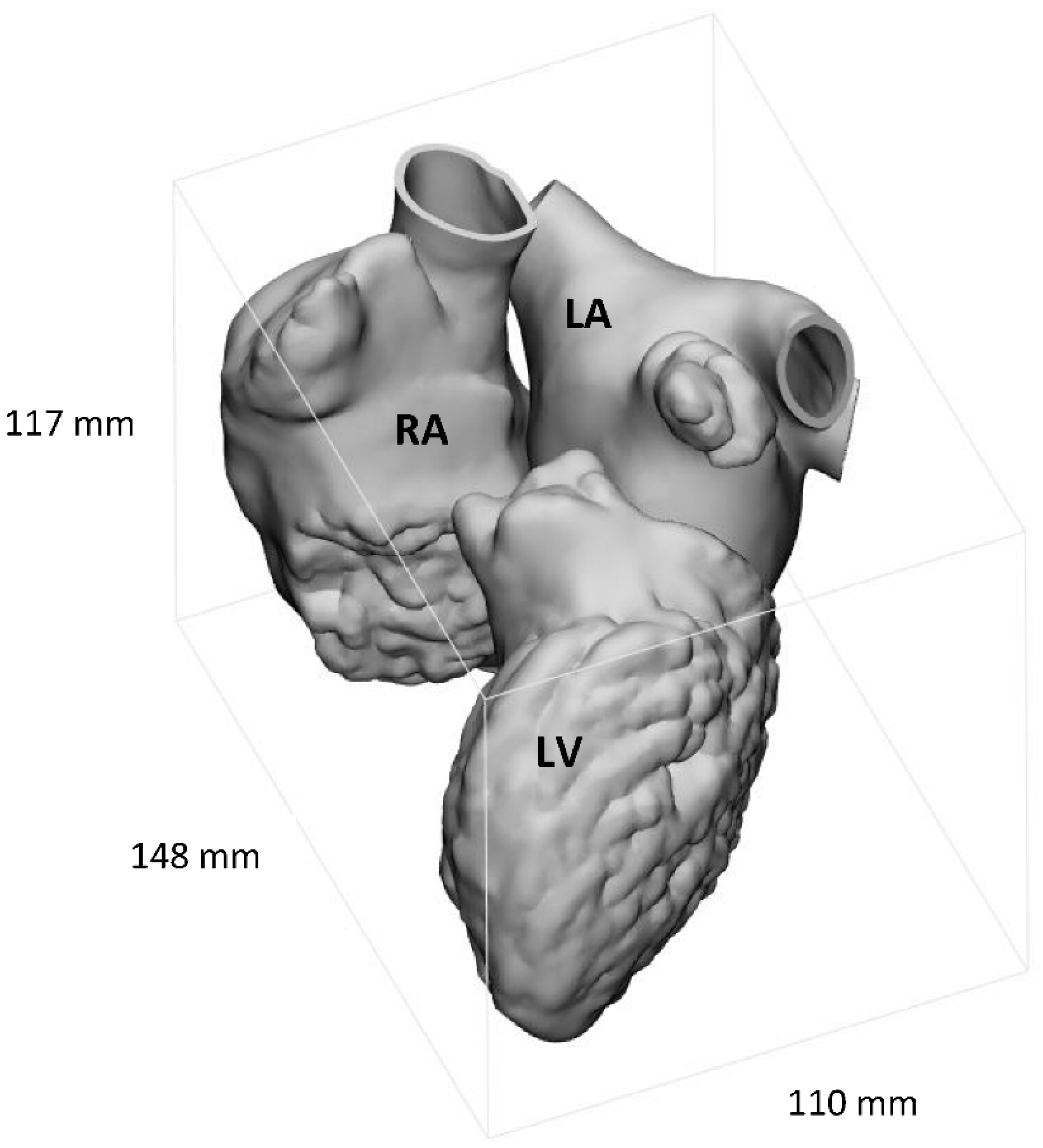
2.1. Image Segmentation
2.2. Computed-Assisted Design Modifications
2.2.1. Additional Anatomical Features
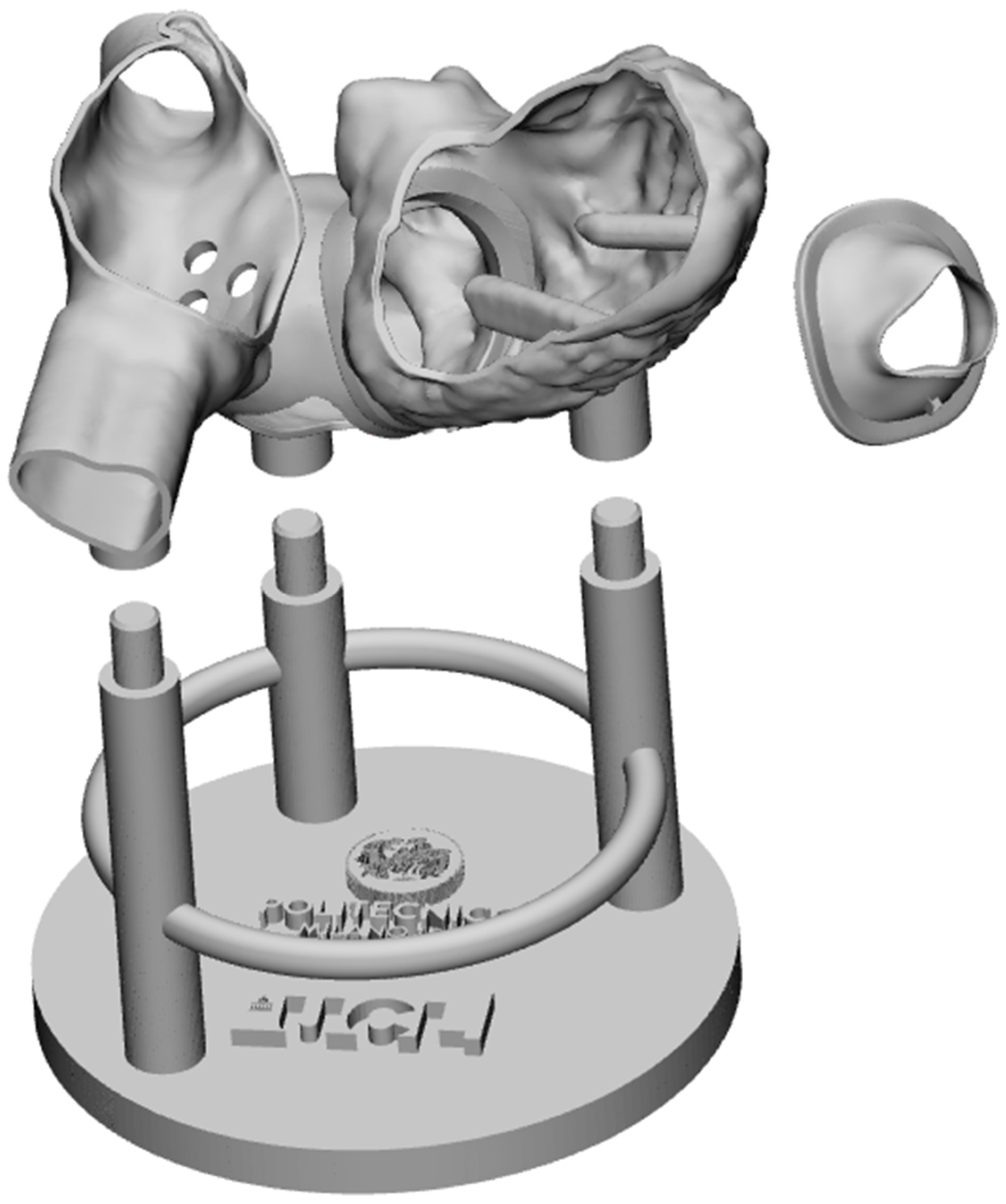
2.2.2. Adaptation of the Model to MCP
2.2.3. System Modularity
2.3. 3D Printing and Assembling
2.4. Testing
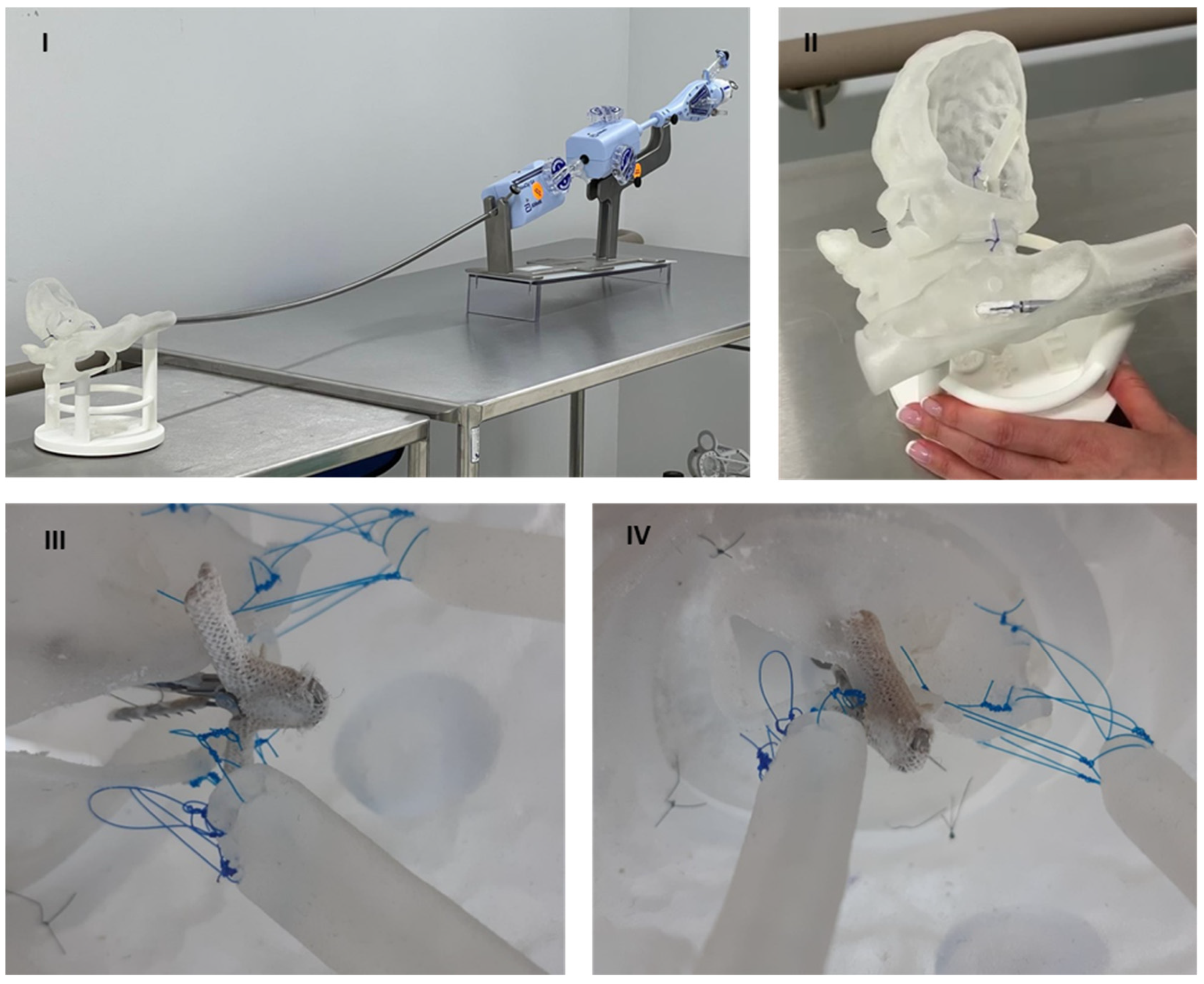
- I.
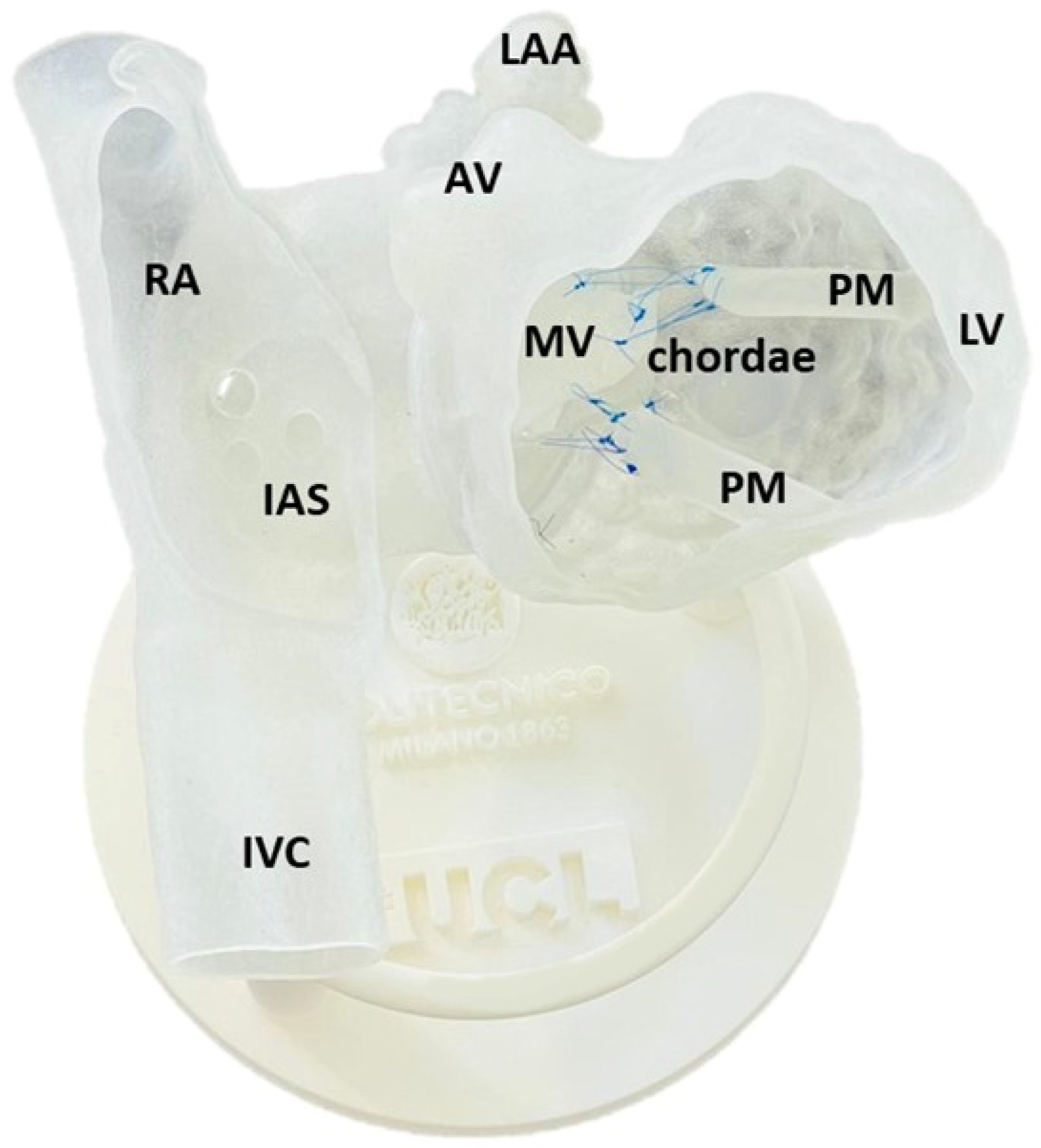
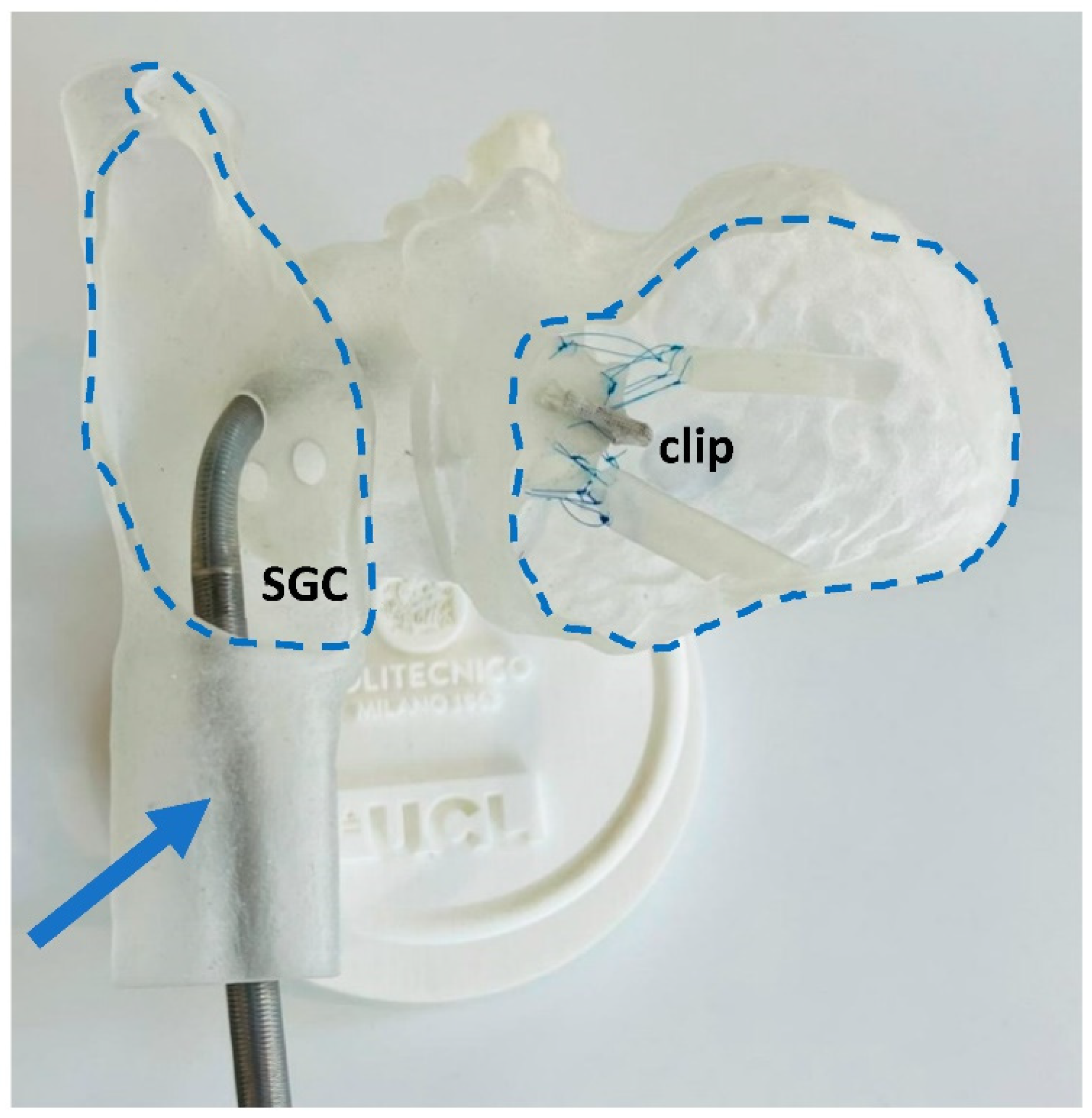
- Preparation. The stabiliser of the MitraClip system was positioned about 80 cm away from the model, ensuring sufficient distance for TSP. The base of the model was stabilised on the table.
- II.
- Guide positioning in the LA and introducing CDS. The steerable guide catheter was advanced through the IVC, then transseptal crossing passage and insertion of CDS through SGC. A series of steering manoeuvres with the SGC and CDS were made to optimise the trajectory and orientation of the clip arms perpendicular to the line of coaptation, under direct visual access through the openings of the model.
- III.
- Advancing into LV through the MV while avoiding interaction with subvalvular apparatus and leaflet grasping. Once in place, MV leaflets were grasped by lowering the grippers and closing clip arms. Qualitative and visual assessments of MR were performed, possibly accompanied by leaflets regrasping, to reach optimal positioning and sufficient grasping.
- IV.
- Deployment simulation and system removal. CDS was removed by releasing deflection on the catheter and slowly removing it from the model.
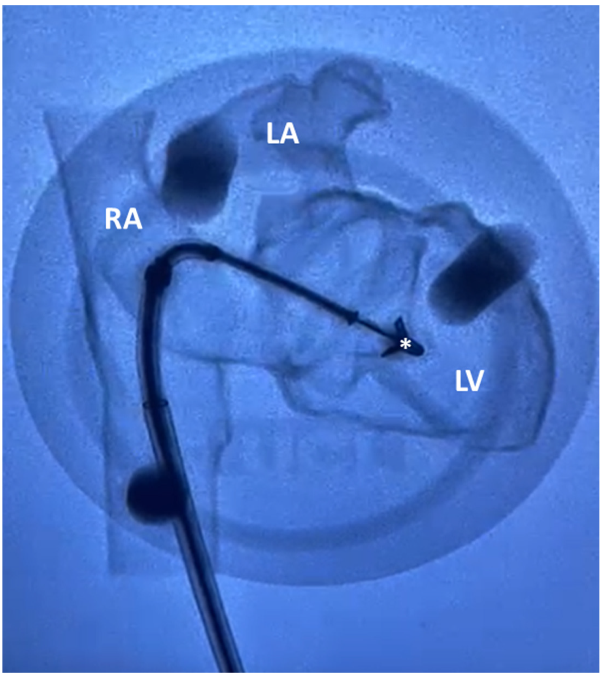
3. Results
4. Discussion and Conclusions
Author Contributions
Funding
Institutional Review Board Statement
Informed Consent Statement
Data Availability Statement
Acknowledgments
Conflicts of Interest
References
- Iung, B.; Vahanian, A. Epidemiology of Acquired Valvular Heart Disease. Can. J. Cardiol. 2014, 30, 962–970. [Google Scholar] [CrossRef] [PubMed]
- Enriquez-Sarano, M.; Akins, C.W.; Vahanian, A. Mitral regurgitation. Lancet 2009, 373, 1382–1394. [Google Scholar] [CrossRef]
- Nkomo, V.T.; Gardin, J.M.; Skelton, T.N.; Gottdiener, J.S.; Scott, C.G.; Enriquez-Sarano, M. Burden of valvular heart diseases: A population-based study. Lancet 2006, 368, 1005–1011. [Google Scholar] [CrossRef]
- Topilsky, Y. Mitral Regurgitation: Anatomy, Physiology, and Pathophysiology—Lessons Learned From Surgery and Cardiac Imaging. Front. Cardiovasc. Med. 2020, 7, 84. [Google Scholar] [CrossRef]
- Cahill, T.J.; Prothero, A.; Wilson, J.; Kennedy, A.; Brubert, J.; Masters, M.; Newton, J.D.; Dawkins, S.; Enriquez-Sarano, M.; Prendergast, B.D.; et al. Community prevalence, mechanisms and outcome of mitral or tricuspid regurgitation. Heart 2021, 107, 1003–1009. [Google Scholar] [CrossRef]
- Starling, M.R. Left ventricular pump efficiency in long-term mitral regurgitation assessed by means of left ventricular-arterial coupling relations. Am. Heart J. 1994, 127, 1324–1335. [Google Scholar] [CrossRef] [Green Version]
- Walther, C.; Fichtlscherer, S.; Holubec, T.; Vasa-Nicotera, M.; Arsalan, M.; Walther, T. New developments in transcatheter therapy of mitral valve disease. J. Thorac. Dis. 2020, 12, 1728–1739. [Google Scholar] [CrossRef]
- Mirabel, M.; Iung, B.; Baron, G.; Messika-Zeitoun, D.; Détaint, D.; Vanoverschelde, J.-L.; Butchart, E.G.; Ravaud, P.; Vahanian, A. What are the characteristics of patients with severe, symptomatic, mitral regurgitation who are denied surgery? Eur. Heart J. 2007, 28, 1358–1365. [Google Scholar] [CrossRef] [Green Version]
- Kay, B.; Chouairi, F.; Clark, K.A.; Reinhardt, S.W.; Fuery, M.; Guha, A.; Ahmad, T.; Kaple, R.K.; Desai, N.R. Comparison of Transcatheter and Open Mitral Valve Repair Among Patients With Mitral Regurgitation. Mayo Clin. Proc. 2021, 96, 1522–1529. [Google Scholar] [CrossRef]
- Alfieri, O.; Denti, P. Alfieri stitch and its impact on mitral clip. Eur. J. Cardio-Thorac. Surg. 2011, 39, 807–808. [Google Scholar] [CrossRef] [Green Version]
- Flint, N.; Price, M.J.; Little, S.H.; Mackensen, G.B.; Wunderlich, N.C.; Makar, M.; Siegel, R.J. State of the Art: Transcatheter Edge-to-Edge Repair for Complex Mitral Regurgitation. J. Am. Soc. Echocardiogr. 2021, 34, 1025–1037. [Google Scholar] [CrossRef] [PubMed]
- Gössl, M.; Farivar, R.S.; Bae, R.; Sorajja, P. Current Status of Catheter-Based Treatment of Mitral Valve Regurgitation. Curr. Cardiol. Rep. 2017, 19, 1382. [Google Scholar] [CrossRef] [PubMed]
- Zuin, M.; Rigatelli, G.; Ronco, F. Worldwide and European interest in the MitraClip. J. Cardiovasc. Med. 2020, 21, 246–249. [Google Scholar] [CrossRef] [PubMed]
- Rogers, J.H.; Franzen, O. Percutaneous edge-to-edge MitraClip therapy in the management of mitral regurgitation. Eur. Heart J. 2011, 32, 2350–2357. [Google Scholar] [CrossRef]
- Pibarot, P.; Delgado, V.; Bax, J.J. MITRA-FR vs. COAPT: Lessons from two trials with diametrically opposed results. Eur. Heart J. Cardiovasc. Imaging 2019, 20, 620–624. [Google Scholar] [CrossRef]
- Imran; Amanullah. Phosphorus and Boron Application Optimizing Biofortification of P and Productivity of French Bean (Phaseolus vulgaris L.). Commun. Soil Sci. Plant Anal. 2021, 52, 2876–2883. [Google Scholar] [CrossRef]
- Quaife, R.A.; Salcedo, E.E.; Carroll, J.D. Procedural Guidance Using Advance Imaging Techniques for Percutaneous Edge-to-Edge Mitral Valve Repair. Curr. Cardiol. Rep. 2014, 16, 1–9. [Google Scholar] [CrossRef]
- Resor, C.D. The TMVr Operator Volume and Outcome Relationship. J. Am. Coll. Cardiol. 2019, 74, 2966–2968. [Google Scholar] [CrossRef]
- Eleid, M.F.; Reeder, G.S.; Malouf, J.F.; Lennon, R.J.; Pislaru, S.V.; Nkomo, V.T.; Rihal, C.S. The Learning Curve for Transcatheter Mitral Valve Repair With MitraClip. J. Interv. Cardiol. 2016, 29, 539–545. [Google Scholar] [CrossRef] [Green Version]
- Bradley, P. The history of simulation in medical education and possible future directions. Med. Educ. 2006, 40, 254–262. [Google Scholar] [CrossRef]
- Laing, J.; Moore, J.T.; Vassallo, R.; Bainbridge, D.; Drangova, M.; Peters, T.M. Patient-specific cardiac phantom for clinical training and preprocedure surgical planning. J. Med. Imaging 2018, 5, 021222. [Google Scholar] [CrossRef]
- Laing, J.; Moore, J.; Bainbridge, D.; Drangova, M.; Peters, T. Patient-Specific Atrium Models for Training and Pre-Procedure Surgical Planning; Progress in Biomedical Optics and Imaging; SPIE: Orlando, FL, USA, 2017; Volume 10135. [Google Scholar]
- Vukicevic, M.; Puperi, D.S.; Grande-Allen, K.J.; Little, S.H. 3D Printed Modeling of the Mitral Valve for Catheter-Based Structural Interventions. Ann. Biomed. Eng. 2016, 45, 508–519. [Google Scholar] [CrossRef]
- Bertolini, M.; Rossoni, M.; Colombo, G. Additive Manufacturing of a Compliant Multimaterial Heart Model. Comput. Des. Appl. 2022, 19, 1162–1170. [Google Scholar] [CrossRef]
- Lam, J.H.C.; Ranganathan, N.; Wigle, E.D.; Silver, M.D. Morphology of the Human Mitral Valve. Circulation 1970, 41, 449–458. [Google Scholar] [CrossRef] [Green Version]
- Park, C.; Kim, J. Development of a three-dimensional-printed heart model replicating the elasticity, tear resistance, and hardness of pig heart using agilus and tango. J. Mech. Med. Biol. 2022, 22, 2240007. [Google Scholar] [CrossRef]
- Severseike, L.; Lee, V.; Brandon, T.; Bakken, C.; Bhatia, V. Polyjet 3d printing of tissue- mimicking materials: How well can 3d printed synthetic myocardium replicate mechanical properties of organic myocardium? BioRxiv 2019, 825794. [Google Scholar] [CrossRef]
- Zimmermann, J.M.; Arduini, M.; Vicentini, L.; Maisano, F.; Meboldt, M. Transcatheter Mitral Valve Repair Simulator Equipped with Eye Tracking Based Performance Assessment Capabilities: A Pilot Study. Cardiovasc. Eng. Technol. 2021, 12, 530–538. [Google Scholar] [CrossRef]
- Fender, E.A.; Nishimura, R.A.; Holmes, D.R. Percutaneous therapies for tricuspid regurgitation. Expert Rev. Med. Devices 2016, 14, 37–48. [Google Scholar] [CrossRef] [PubMed]
- Nickenig, G.; Kowalski, M.; Hausleiter, J.; Braun, D.; Schofer, J.; Yzeiraj, E.; Rudolph, V.; Friedrichs, K.; Maisano, F.; Taramasso, M.; et al. Transcatheter Treatment of Severe Tricuspid Regurgitation With the Edge-to-Edge MitraClip Technique. Circulation 2017, 135, 1802–1814. [Google Scholar] [CrossRef]
- Debonnaire, P.; Coussement, P.; Van Der Heyden, J. Transcatheter tricuspid valve repair using MitraClip device for significant tricuspid regurgitation: Novel treatment for a common problem. Acta Cardiol. 2019, 75, 793–794. [Google Scholar] [CrossRef] [PubMed]


Publisher’s Note: MDPI stays neutral with regard to jurisdictional claims in published maps and institutional affiliations. |
© 2022 by the authors. Licensee MDPI, Basel, Switzerland. This article is an open access article distributed under the terms and conditions of the Creative Commons Attribution (CC BY) license (https://creativecommons.org/licenses/by/4.0/).
Share and Cite
Bertolini, M.; Mullen, M.; Belitsis, G.; Babu, A.; Colombo, G.; Cook, A.; Mullen, A.; Capelli, C. Demonstration of Use of a Novel 3D Printed Simulator for Mitral Valve Transcatheter Edge-to-Edge Repair (TEER). Materials 2022, 15, 4284. https://doi.org/10.3390/ma15124284
Bertolini M, Mullen M, Belitsis G, Babu A, Colombo G, Cook A, Mullen A, Capelli C. Demonstration of Use of a Novel 3D Printed Simulator for Mitral Valve Transcatheter Edge-to-Edge Repair (TEER). Materials. 2022; 15(12):4284. https://doi.org/10.3390/ma15124284
Chicago/Turabian StyleBertolini, Michele, Michael Mullen, Georgios Belitsis, Angel Babu, Giorgio Colombo, Andrew Cook, Aigerim Mullen, and Claudio Capelli. 2022. "Demonstration of Use of a Novel 3D Printed Simulator for Mitral Valve Transcatheter Edge-to-Edge Repair (TEER)" Materials 15, no. 12: 4284. https://doi.org/10.3390/ma15124284