2.1. Parametric Description of a Single-Blade Rotor with Aspect of Its Geometrics and Aerodynamics
The construction process of helicopter rotor blades requires consideration of fatigue, strength, stiffness, cost, and vibrations. The rotor blade works in a changeable environment, and therefore, the designer has to take into consideration all of the parameters that transform during flight. Periodic changes in the flow velocity on the blade section can modify the angle of attack and the Mach number, and as a consequence, can change the aerodynamic coefficients. Blade turns (relative to hinge axis) and blade deformation cause a periodic change in inertial forces and provoke a cyclic modification in the angles of attack and flow velocity. The flexibility of the main rotor blades and their work in a strong centrifugal force field induce an inseparable connection between loads and deformations. An analysis of the problems mentioned and also the noise level or flow disturbance requires a versatile evaluation of the main rotor blade’s work conditions. Effective blade aerodynamic modeling was proposed in [
25].
The precise blade geometric design is crucial for obtaining the required main rotor power. As described in [
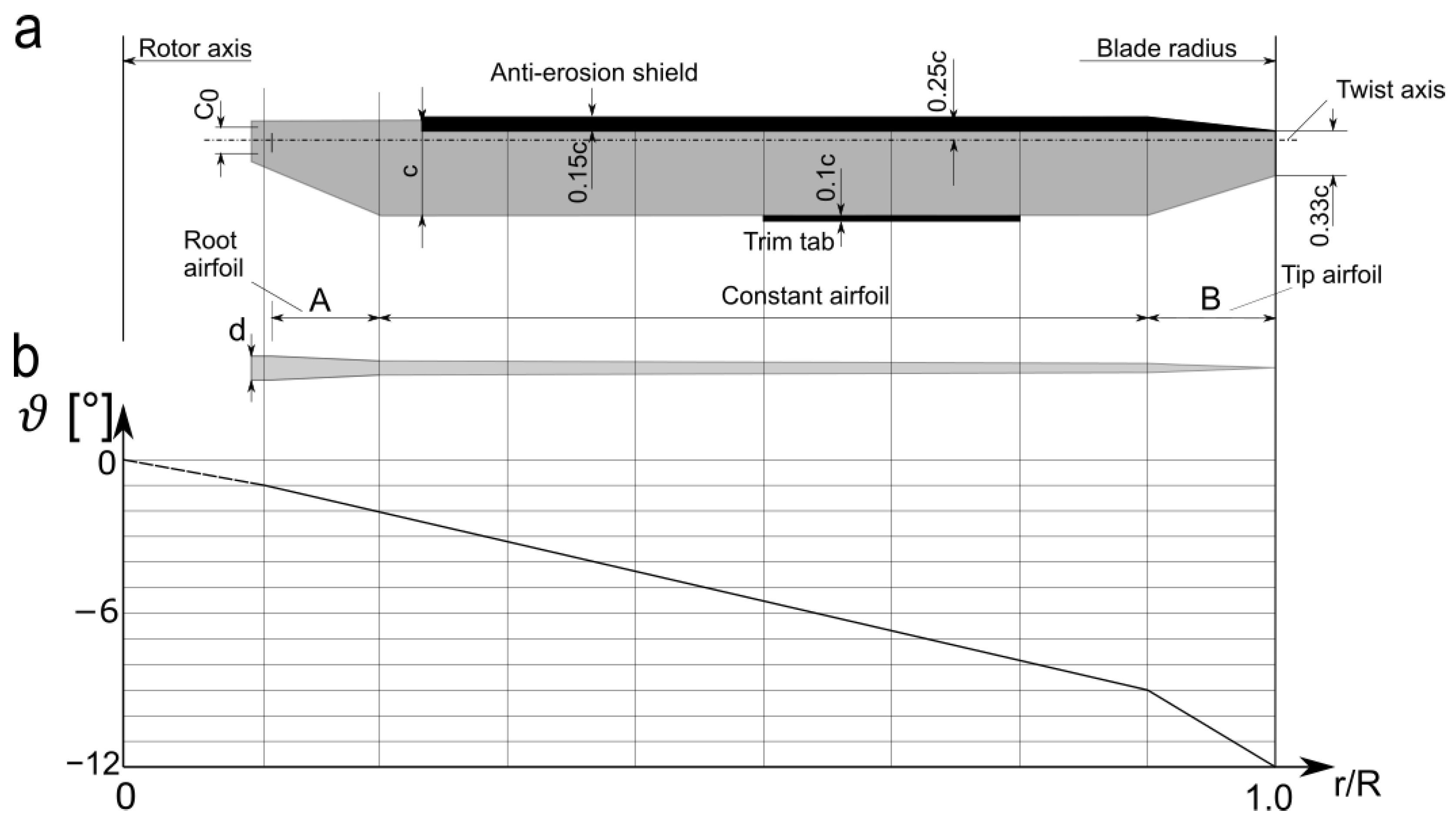
26], the geometric parameters of the blade are the following:
- -
Radius The length of the blade measured from the axis of rotation to the tip;
- -
Chord The length of the blade measured from the airfoil leading edge to the trailing edge and, for a tapered blade, it is the function of local radius;
- -
Airfoil The cross-sectional shape that determines the aerodynamic parameters of the blade, i.e., lift, drag and momentum coefficients;
- -
Contour shape This is the final shape of the blade, which depends on the chord function and tip shape;
- -
Geometric twist Variation of the airfoil angle between the chord and a plane of rotation along the radius;
- -
Aerodynamic twist Variation of the airfoil shape along the radius;
- -
Position and shape of trim tabs Defines the possibility to adjust the rotating blade to the plane of rotation.
The area of a blade root airfoil transfers the whole load from the rotating aerodynamic surface to the blade grip sticking out of a rotor head block. The shape of the root is dictated by the build conception and the adopted aerodynamic solutions. The geometric twist is usually settled on several degrees. The shape of the rotor tip depends on the aerodynamic problems, for example, achieving the speed of sound or the noise level. An analysis of rotor blade tips was described in [
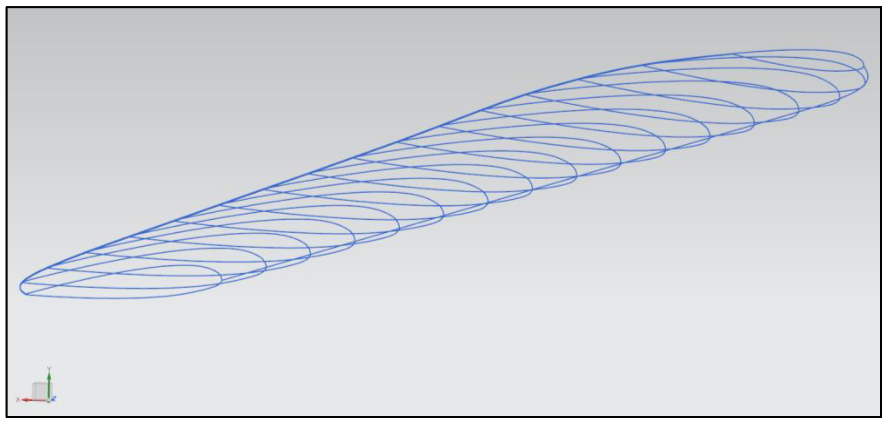
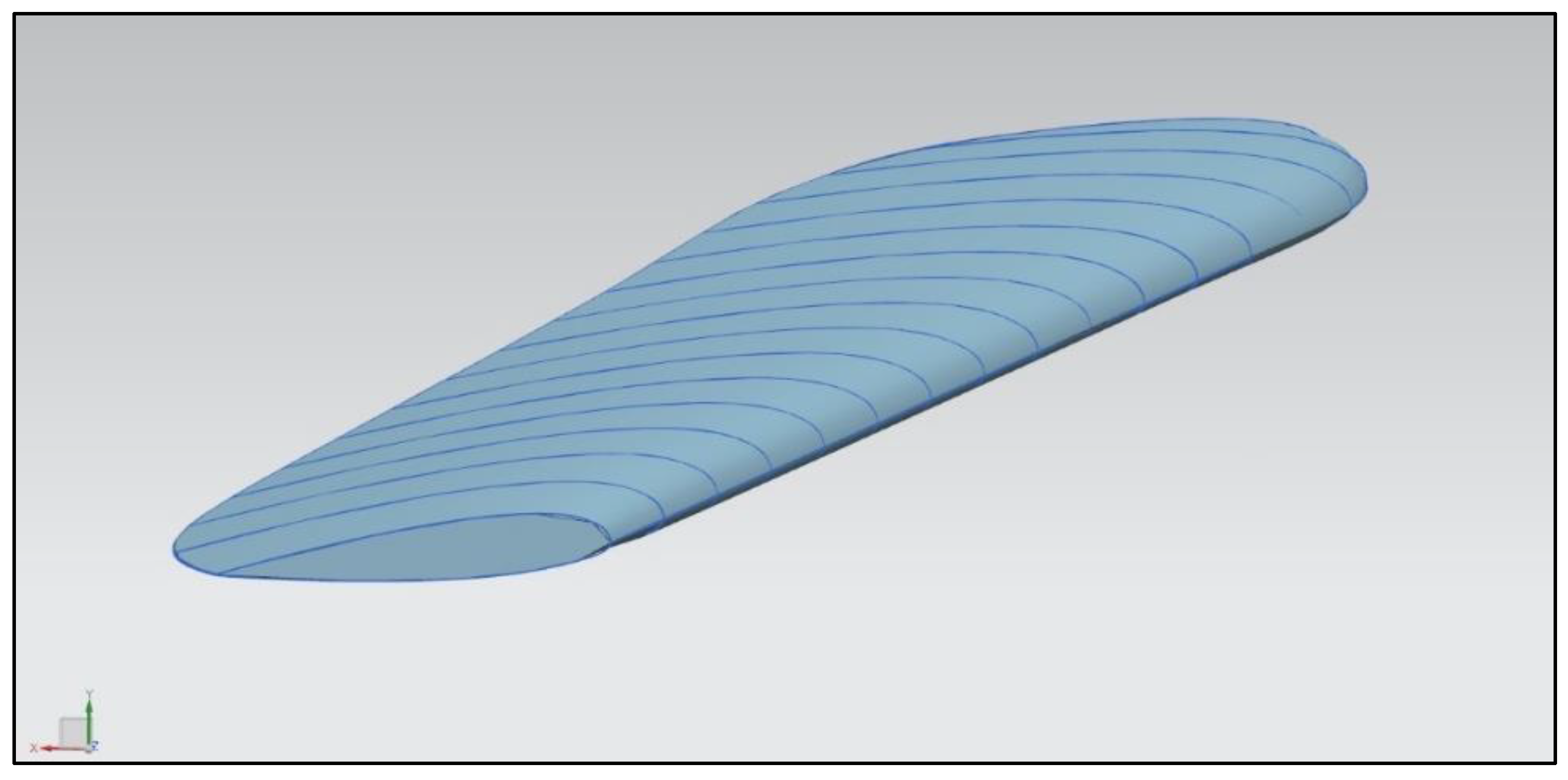
27]. According to the mentioned work, there are three main types of helicopter tip designs: BERP tip, the parabolic tip, and the swept (tapered) tip. An example of a main rotor blade is shown in
Figure 1.
To evaluate the prepared parametric model, a theoretical lift calculation must be conducted. The lift can be calculated in vertical flight using the blade element theory combined with the momentum theory. The first assumptions are the mass conservation equation for rotor disc:
and the momentum conservation equation for hoovering rotor:
The energy conservation equation is the work of the rotor to change the rate of energy in fluid:
The calculation is based on the thrust coefficient, as a function of pitch angle and inflow angle, and is given [
28,
29]:
where
a is the lift curve slope,
is the rotor solidity,
is the pitch angle,
is the inflow angle, and r is the current radius.
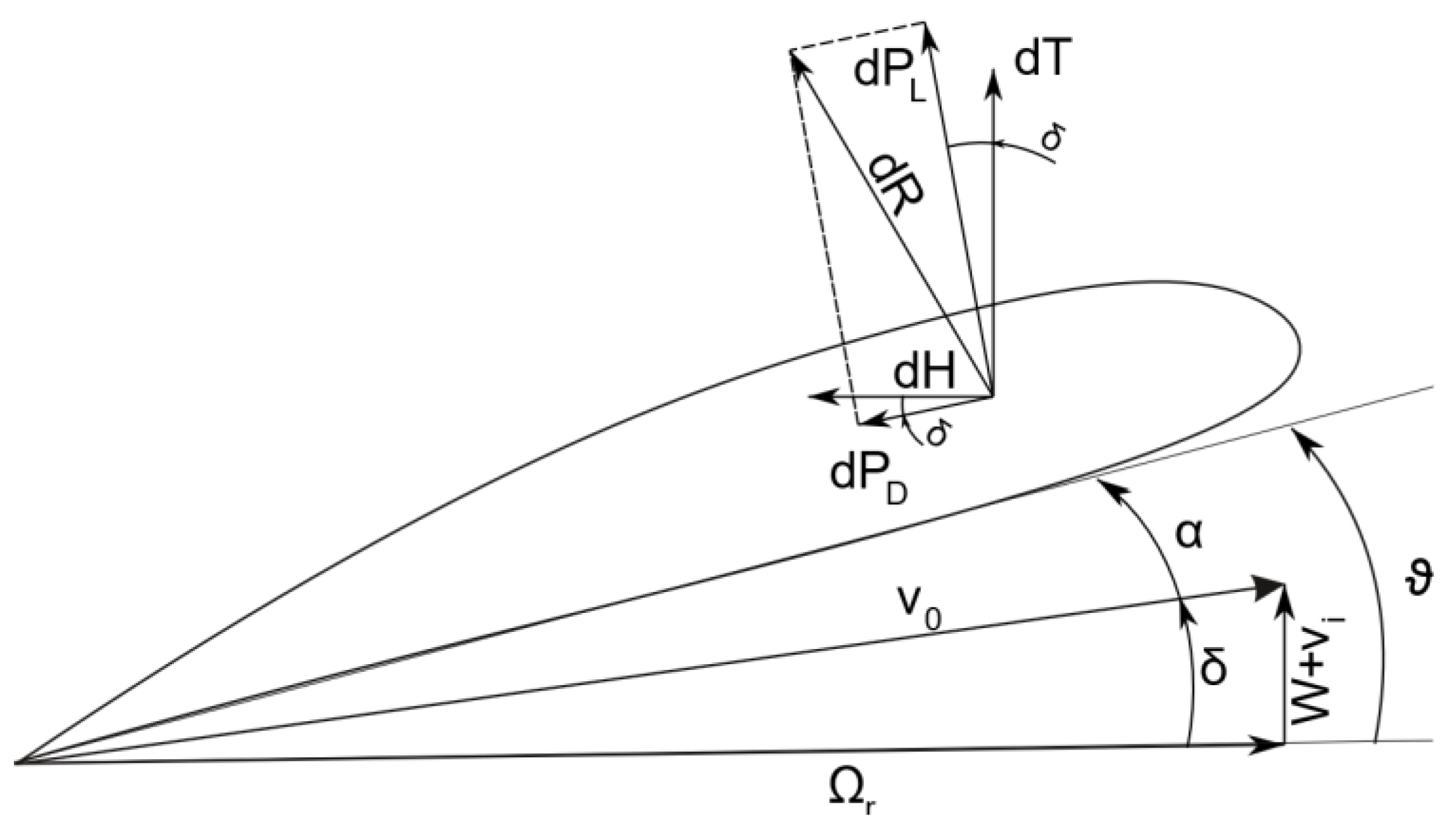
According to
Figure 2, the inflow angle
δ can be defined by:
where
is the vertical velocity,
is the induced velocity, and
is the rotor angular velocity.
To calculate the induced velocity, for required thrust in hover, the equation solved from the momentum theory is given:
where
T is the rotor thrust,
is the air density, and
A is the rotor planform area. For hover, the
W velocity equals 0.
The inflow angle can be defined with the inflow ratio as
, therefore, the thrust coefficient will transform to:
Rotor performance can be calculated with the combination of the blade element theory with the momentum theory. Therefore, the induced velocity can be determined for nonhomogeneous inflow distribution, by using the differential form of the momentum theory:
with the blade element theory
equation form.
As a result, for hover where
, the inflow ratio for the induced velocity is:
The
rotor solidity equation is necessary, which, in this work, is nonuniform along the blade span as a consequence of non constant chord. The rotor solidity is calculated as:
where
b is the number of blades,
c(
r) is the chord in function of radius, and
R is the rotor radius.
The thrust coefficient is the function of radial location of the blade measured from the centre of rotation to the blade tip. It is calculated as an integral with the
limits from 0 to 1. However, to obtain better quality results, a tip loss factor can be proposed [
30]:
The tip loss factor is taken as an upper limit of the coefficient integral. The thrust losses are also a result of the root cutout. It is usually 10% to 30% of the blade radius. Including tip loss factor and root cutout, the thrust integration is:
According to [
22], the mean lift coefficient for the main rotor blade can be determined:
The calculations described above were all prepared in MATLAB. The estimated mathematical thrust model is the basis for the CFD computation evaluation.
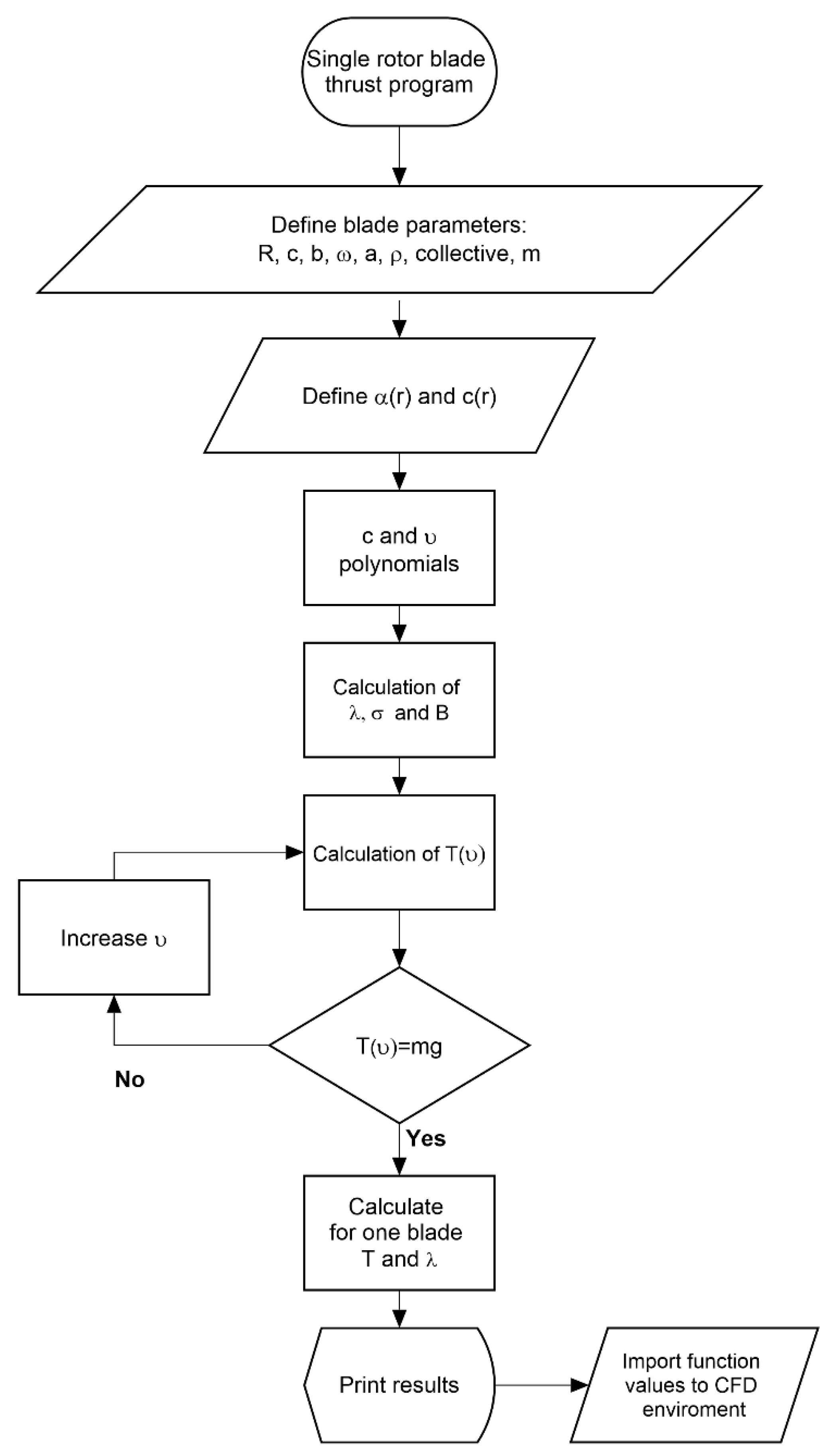
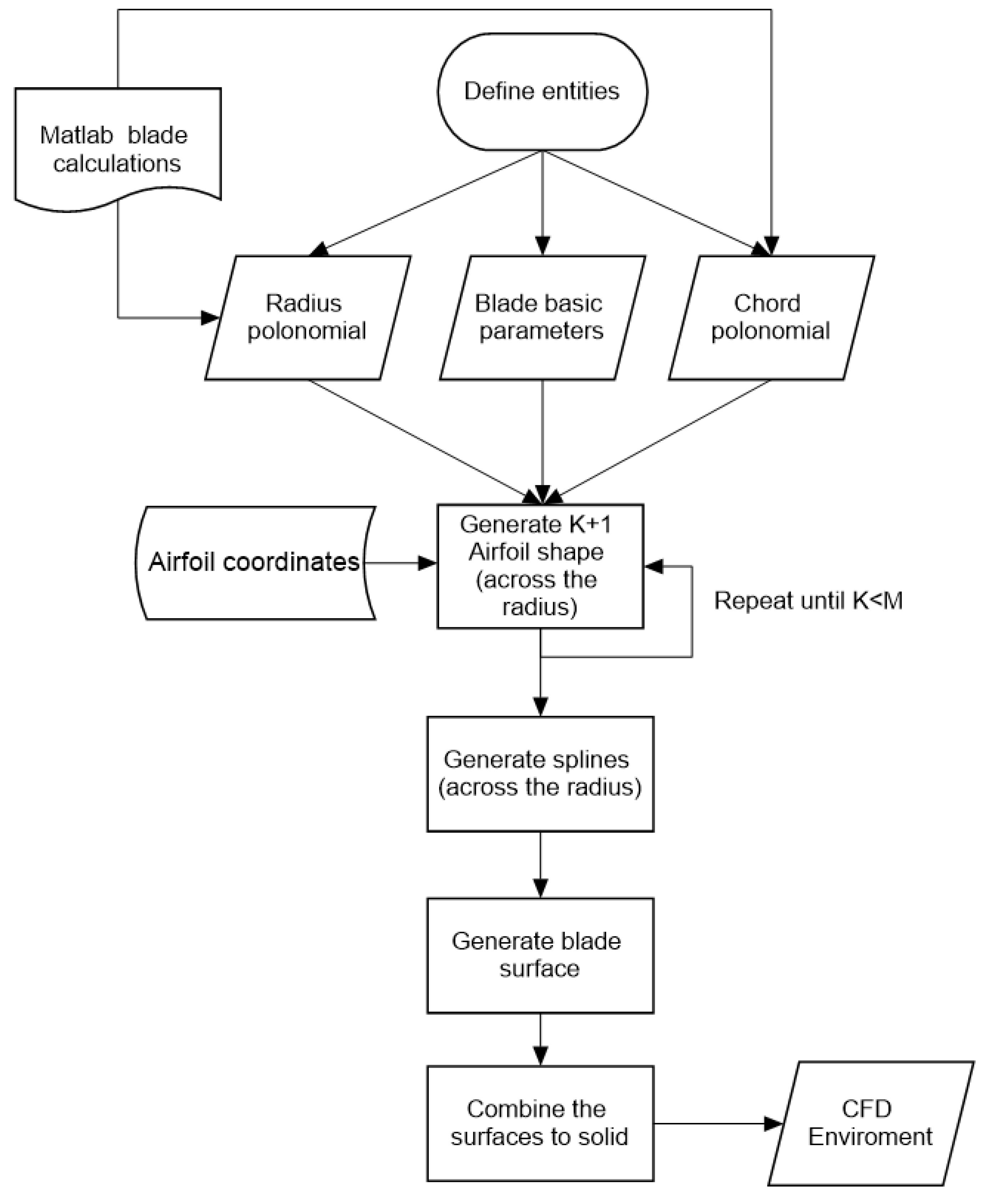
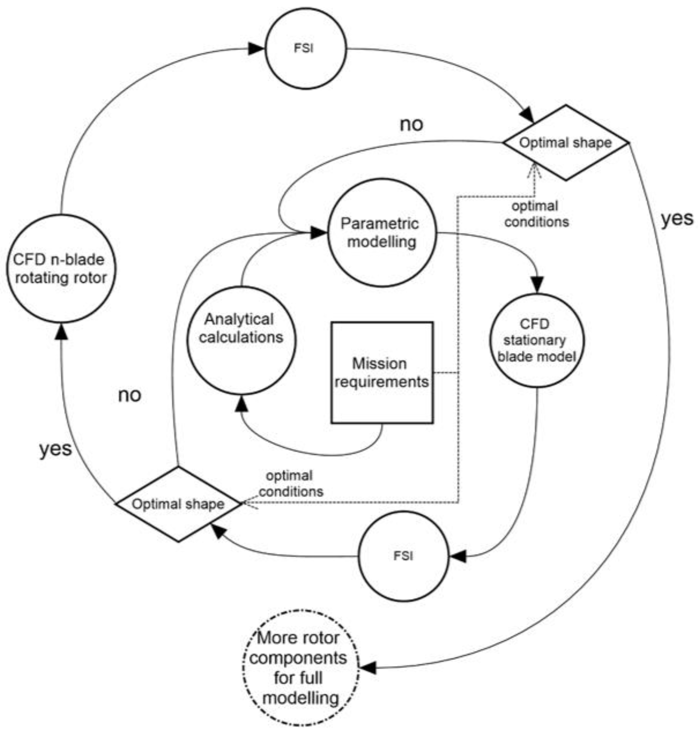
The program build is defined using the algorithm presented in
Figure 3. The code is constructed as a loop to look for the collective angle required for a given aircraft weight.
It starts by defining the input parameters that can be obtained from first cut calculations and the mission flight conditions. In the beginning, the collective is positioned at 0° angle. Next, the position radius coordinates are defined for the twist and chord values in the given sections. The thrust is a radius position integral, and therefore, all program functions are defined as dependent on x. Using the chord and twist values, the chord and twist polynomials are interpolated. These polynomials are also used in the GRIP program to create the blade geometrics. Next, the inflow angle, the rotor solidity, and tip loss factor are given. All the specified equations are inputs to the thrust integral which is bounded by the root cutout and the tip loss factor. The blade attack angle is calculated using the pitch angle with addition of collective. The thrust equation is computed using loop. The collective angle is increased in each step until the result is similar to the hover required force for the assumed mass. The determined collective is used for the CFD analysis to check the parametric model aerodynamic parameters. The procedure described above can be applied for the hover case calculations and for vertical or horizontal flight conditions as well.
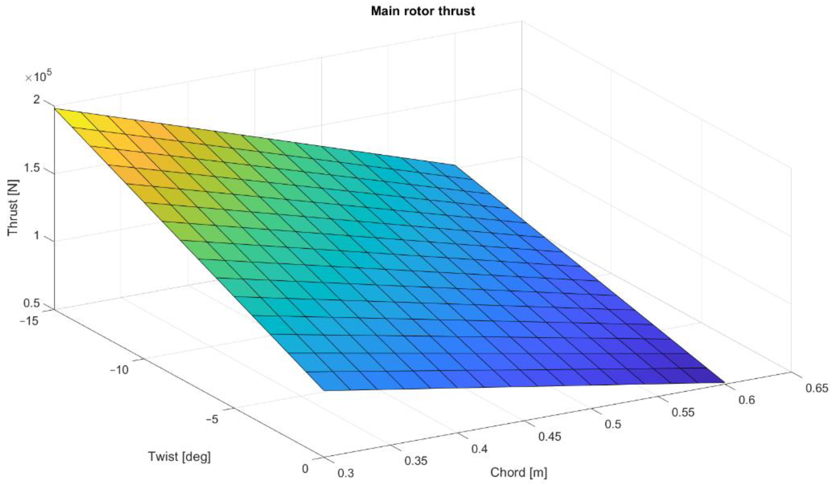
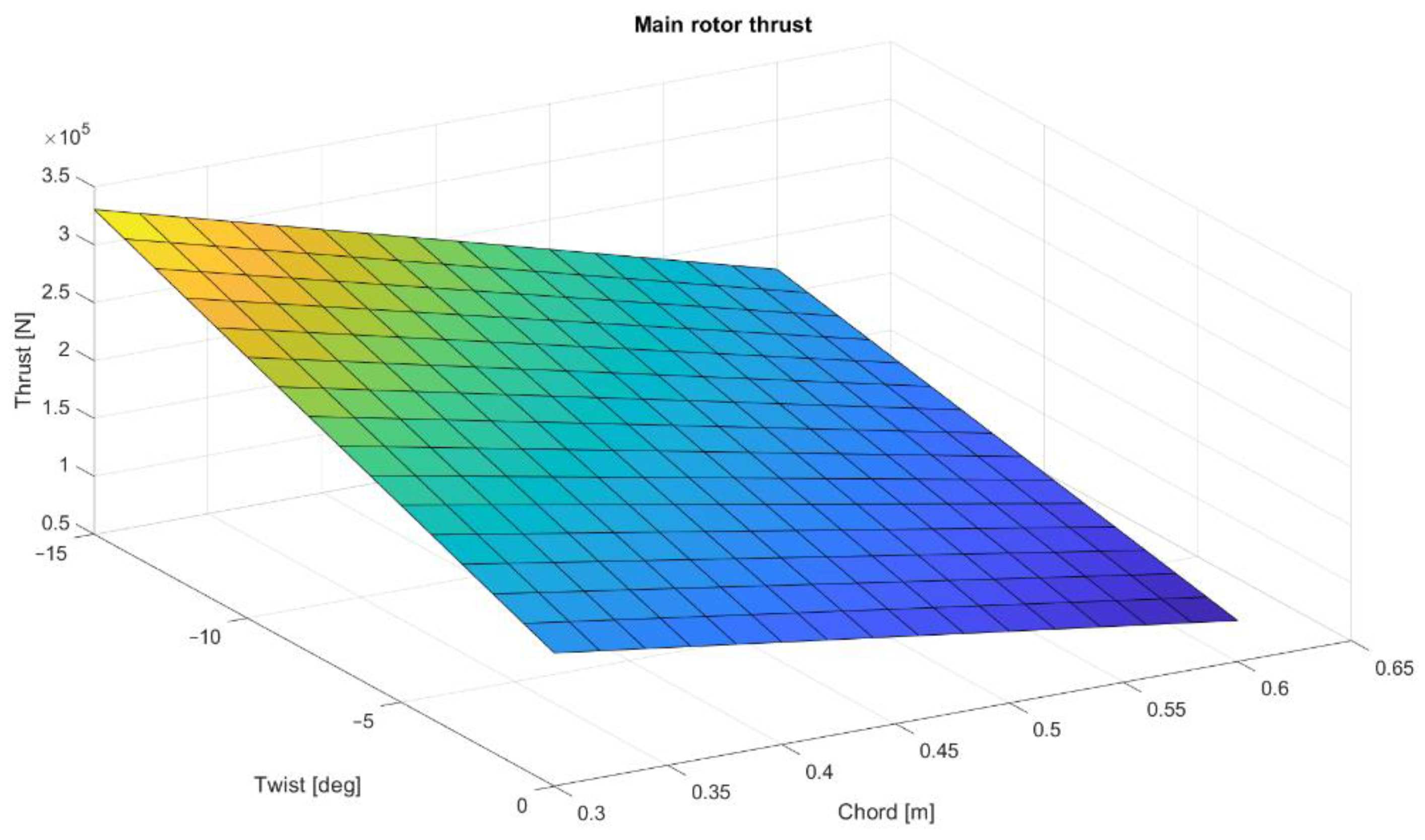
To present the possibilities of Matlab calculations for future main rotor optimization, a multi-dimensional analysis was conducted. The main rotor thrusts were calculated for different numbers of blades, twist angles, and mean chord values. The computations were made for the collective angle 7.47°. The distribution of thrust values as a function of twist angle and chord value are shown in
Figure 4,
Figure 5 and
Figure 6. As predicted, the highest thrust value is obtained for a five-blade rotor, although the reference system is a four-blade rotor, corresponding to the rotor design of the Polish W-3 Sokol helicopter.
2.3. Aerodynamic Modeling of a Single-Blade and Complete Main Rotor
The generated model was implemented in two computer environments to evaluate the properties of the obtained blade shape. The main rotor blade was implemented in a CFD software, i.e., ANSYS Fluent and an aerodynamic modeling software, i.e., DARcorporation Flightstream. The domain for CFD was prepared in ANSYS Spaceclaim. The air density in the simulations was 1.25 kg/m3 and it was constant.
The implementation was conducted to assess the model and to prepare its applicability in further research; however, it was also conducted to compare two different tools for aerodynamic rotorcraft analysis with mathematical calculation. With the results of the CFD analysis, a further strength analysis is possible. In addition, the CFD analysis is a crucial step in the optimization process of a modern main rotor blade design.
2.3.1. One Blade CFD Modeling in ANSYS Fluent
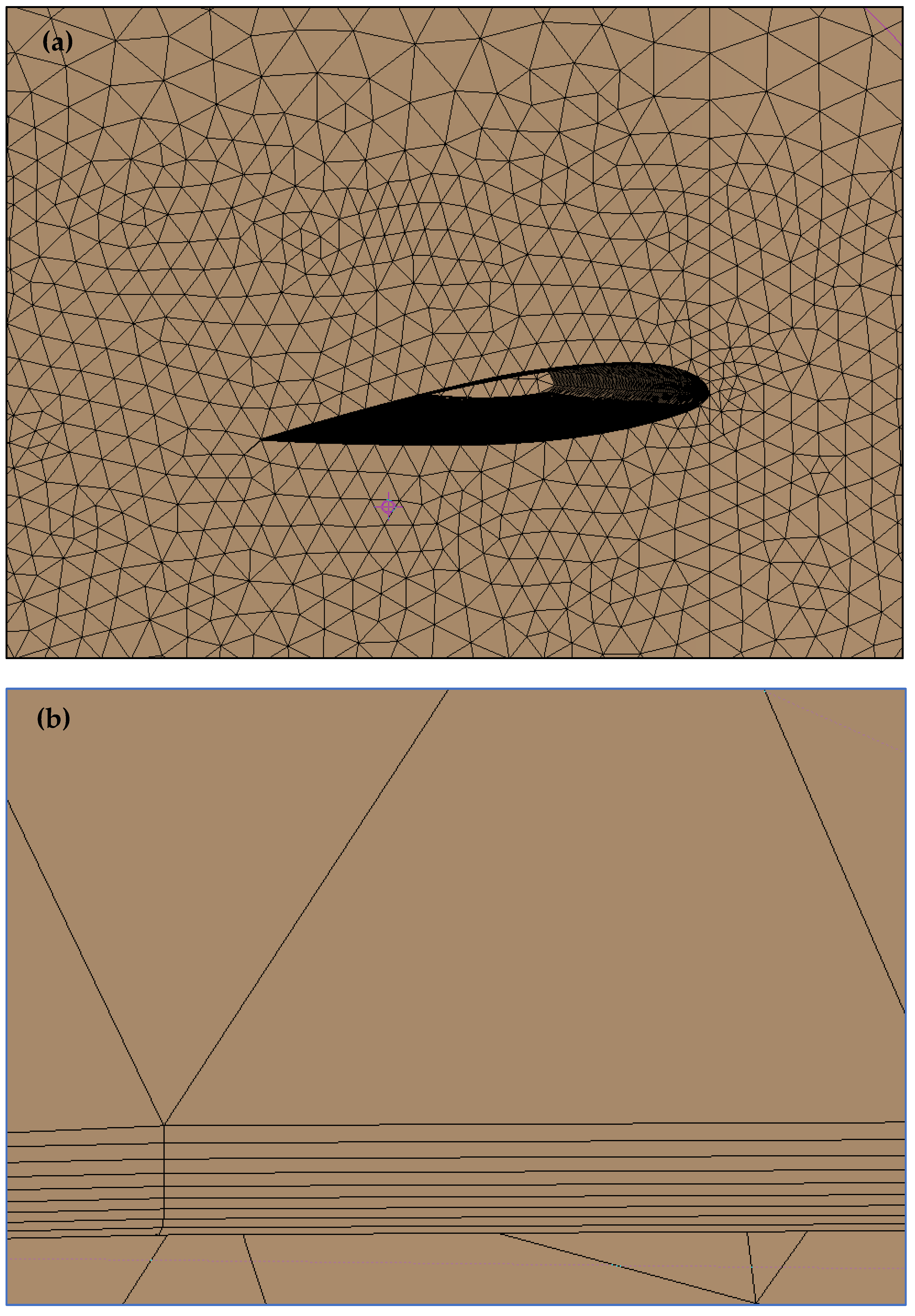
In ANSYS Fluent, a one blade CFD model was prepared. The fluid domain was prepared using Ansys Spaceclaim. It was generated with a quarter of a sphere and half of a cylinder. The air enclosure were 20 m long and high, and the width of the enclosure was 10 m. A hybrid mesh was built for the computational area using the ANSYS Mesh module. Body and face sizing were used with inflation to generate the correct mesh. The boundary layer was modeled using the full thickness option. It was set at 20 mm for 25 layers with a growth ratio of 1.2. The obtained y+ value was 8. The maximum element size was set at 1000 mm, with a size reduction closer to the blade of 20 mm. The 3D bodies were transformed into a tetrahydra mesh with prismatic components within the boundary layer. The mesh consisted of almost 2,837,051 elements. The mesh is shown in
Figure 10.
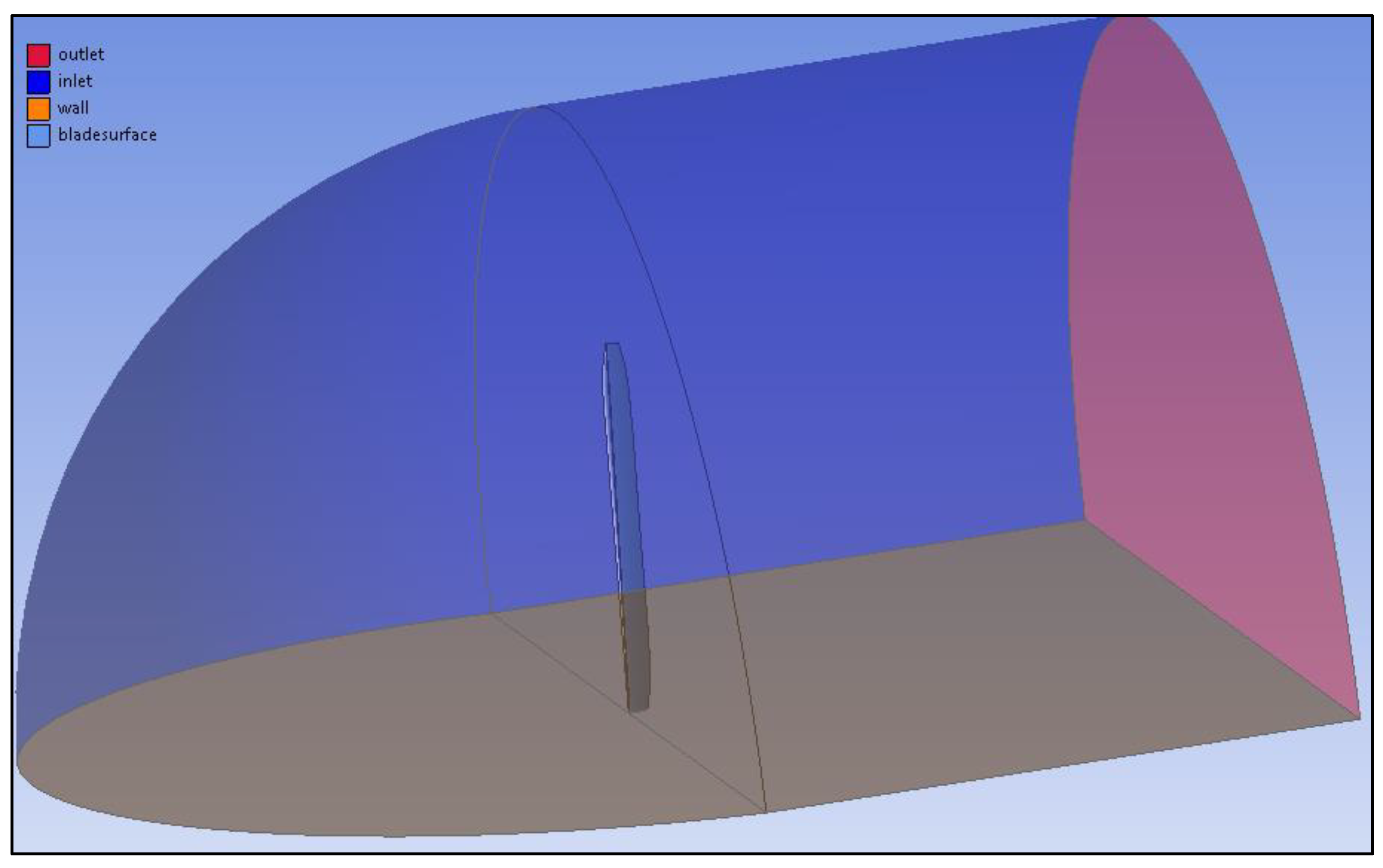
The boundary conditions are presented in
Figure 11. The blade is fixed in the enclosure which is modeled by combining half of a hemisphere with a cylinder. In addition, to obtain correct body sizing, a smaller cuboid enclosure was made around the blade, and by naming the object faces, an air flow direction was projected.
To imitate the main rotor blade working environment, velocity change, pitch, and inflow angle were implemented with mathematical expressions. A velocity change was realized by an expression that raised the inflow speed with the span. To model a change in the inflow angle, the inflow directions on the
X and
Y axes were expressed using the cosine of the
X axis and sine of the
Y axis. The inflow angle was calculated from the inflow ratio with the Matlab program.
Table 2 presents the inflow input function to model the air flow over the blade. The polynomial was a 4th grade polynomial, the higher grades gave similar results. The functions values changed with the span.
The viscosity model which was used for simulations was k-omega SST. It was applied because it is recommended for rotating machinery.
2.3.2. One Blade Panel Modeling in FligtStream
In the second aerodynamic environment, a main rotor blade model was also prepared. The parametric blade model was easily implemented. Software was used to import the CAD files from commercial software, and therefore, the tool could be used in the optimization loop.
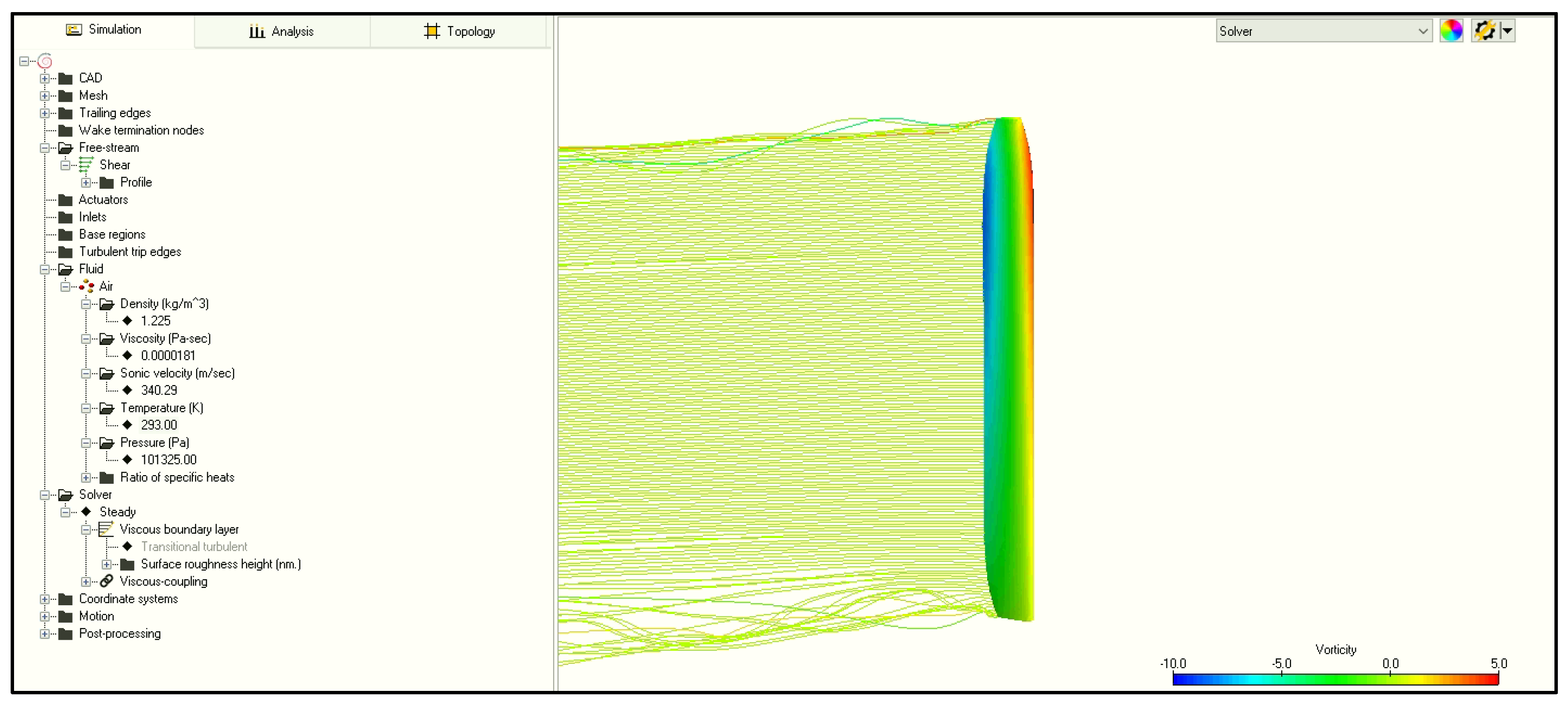
In the Flightstream, the mesh is generated only on the studied element. It does not required from user preparing an enclosure and environment. The mesh is generated automatically by the software. Because of the simplicity of the software, the inflow angle and the change of the pitch angle were modeled with the blade position in the reference frame. Velocity change was simulated by the build “shear” freestream option and prepared input .txt file with the velocity magnitude across the span. The advantage of the solver is the fact that the model for conducting a simulation is ready to use three–four times faster than in the Fluent environment. However, rotorcrafts are complex constructions that work in versatile conditions, and therefore, some working states may not be imitated. The solver was setup with steady viscous parameters. The solver setup is shown in
Figure 12.
2.3.3. Main Rotor CFD Modeling in ANSYS Fluent
In the second stage of the research, the blades were multiplied and positioned in a rotational plane. The fluid domain were also modeled in Spaceclaim. A mesh was built for the computational area using the Mesh Ansys module. The boundary conditions are presented in
Figure 12. Body sizing and inflation were used to generate the correct mesh. The boundary layer was modeled using the full thickness option. The air enclosure was 75 m long and wide, and the height of the enclosure was 25 m. The maximum element size was set at 2000 mm, with a size reduction closer to the blade of 20 mm. The boundary layer was modeled using the full thickness option. It was set at 20 mm for 25 layers with a growth ratio of 1.2. The obtained y+ value was 8. The 3D bodies were transformed into a triangular mesh. The mesh consisted of nearly 5,300,000 elements.
The blades were placed in the enclosure which was modeled with cuboid. In addition, to obtain correct body sizing, a smaller cylinder enclosure was made around the blades. By naming the object faces, an air flow direction was projected. The analysis was performed with mesh motion, and therefore, there was no inlet, because the air flow was provoke by the rotating blades. The boundary conditions are presented on
Figure 13.
The blades were set at the pitch angle calculated for the required thrust. The models were set to rotate with the main rotor angular speed. The inflow angle was assumed to be generated in the solver with the rotational movement. The viscosity model for the simulation that produced the most accurate results with the lowest time consumed was realizable k-epsilon with scalable wall function.
2.3.4. Main Rotor Panel Modeling in FligtStream
Since the modeling was performed using CFD software, the panel environment was also tested to provide results for parametric modeling in the optimization procedure. The model building was more time-consuming and it was easy to make a mistake, because the pitch angle and inflow angle were modeled by the blade’s position. The blades were multiplied and positioned in a rotational plane. The mesh was generated the same way as it was generated for the one blade case. The cases were calculated with an unsteady solver. The rotational movement was modeled with motion settings, where the angular velocity and rotation axis could be defined.


