
A Study on the Bond–Slip Relationship of the CFRP–Steel Interface of CFRP Strengthened Steel


Abstract
:1. Introduction
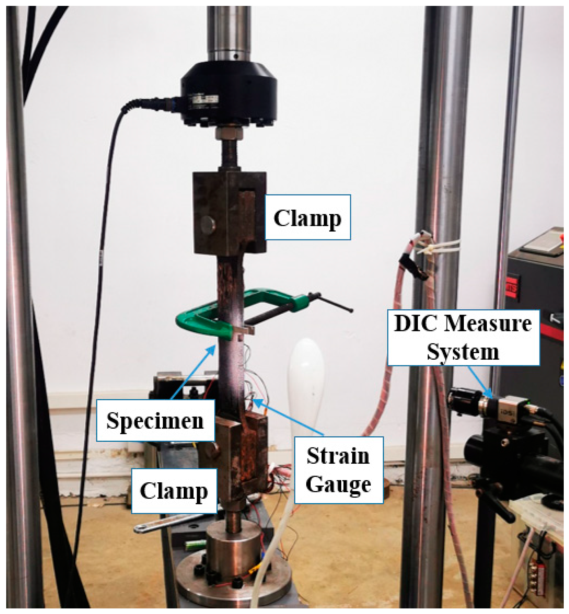
2. Double-Strap Experiment
3. Test Results
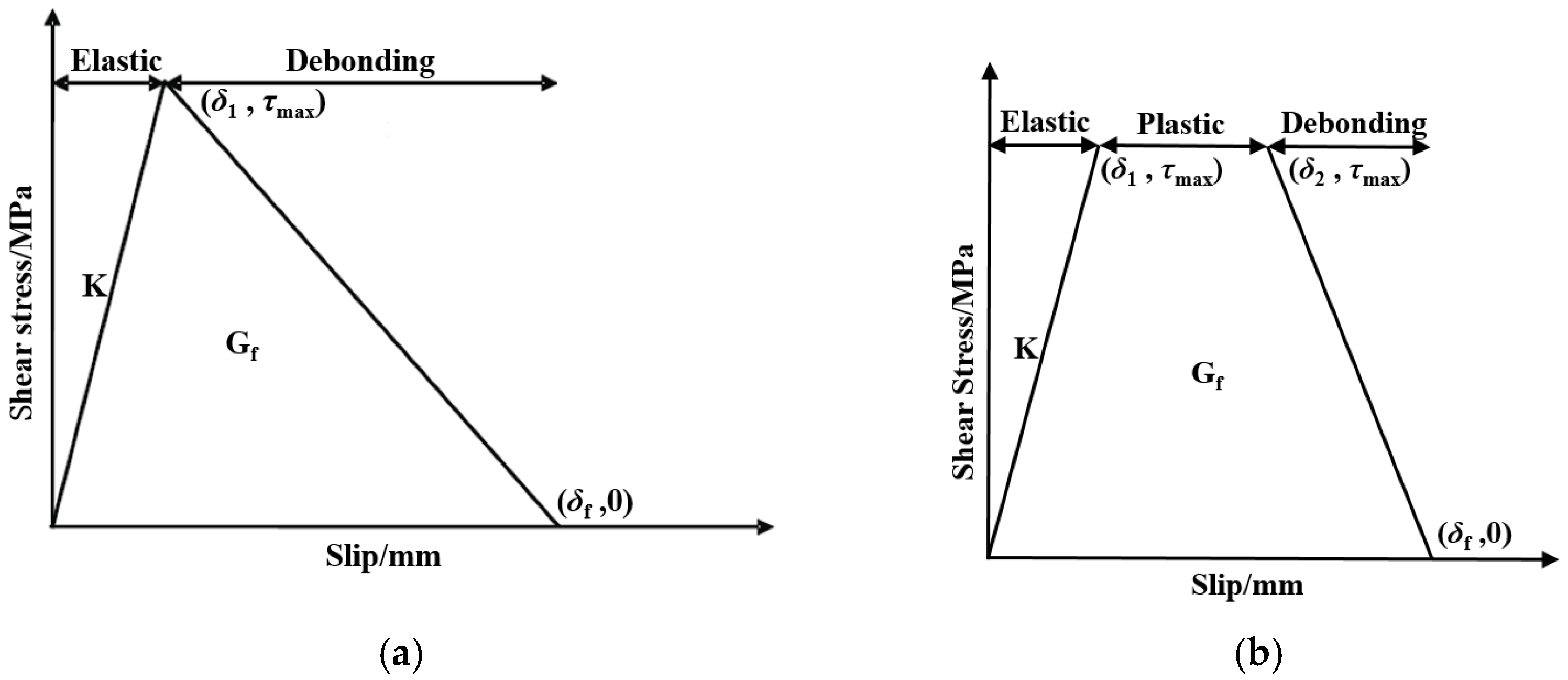
4. Comparison of Bond–Slip Models
5. Numerical Simulation Analysis
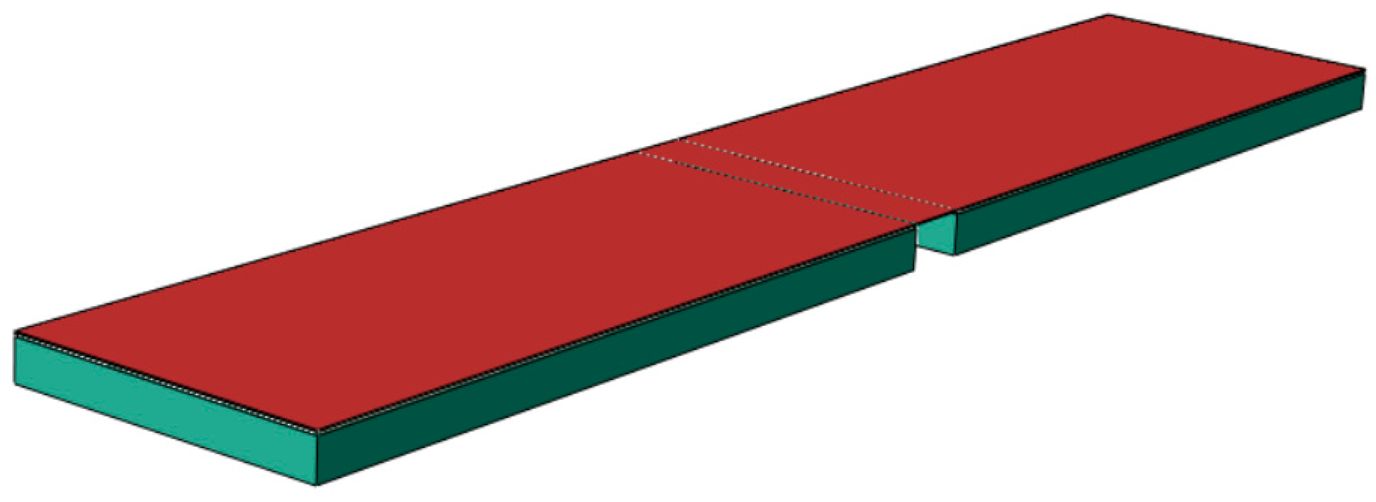
5.1. Finite Element Model
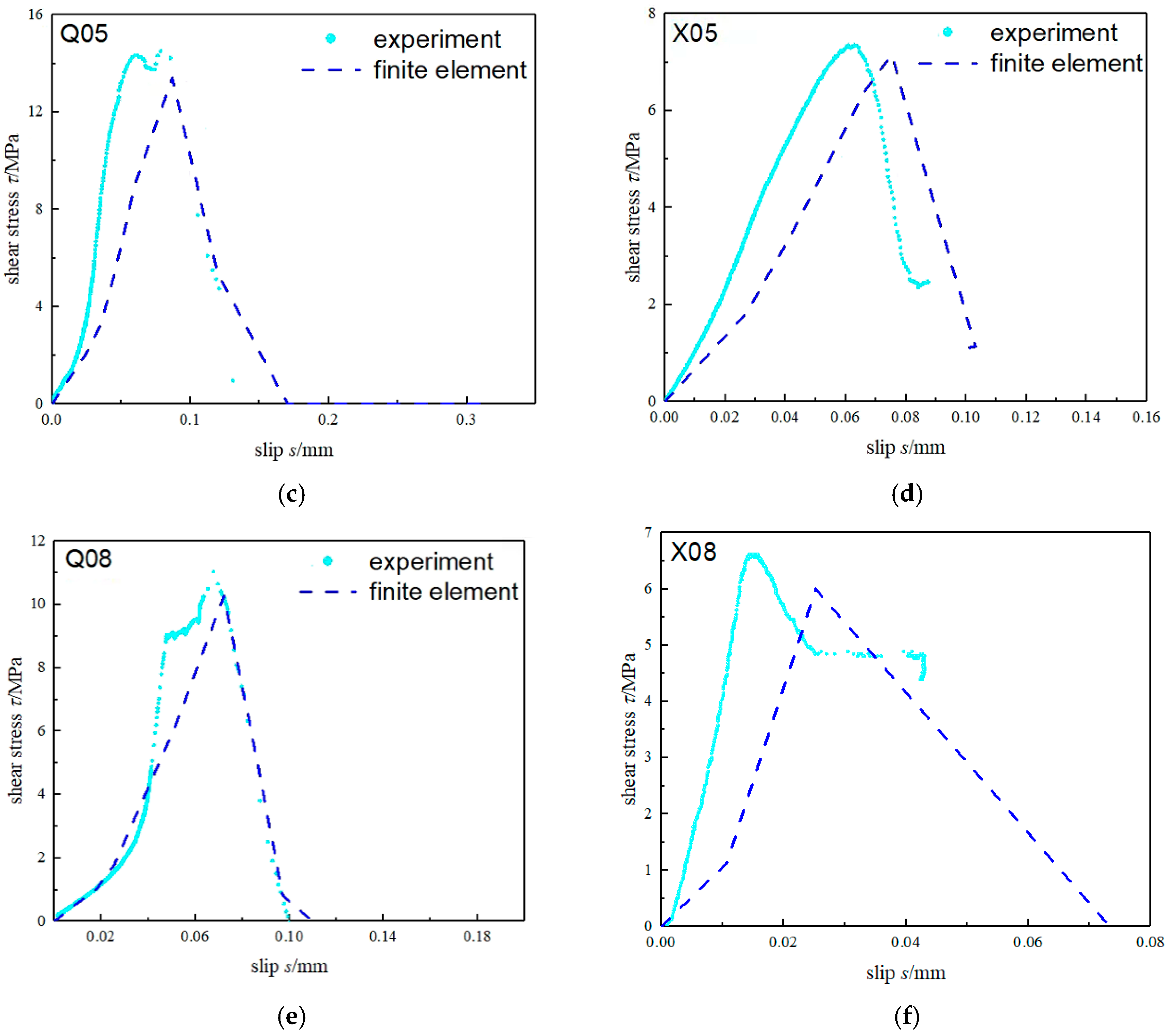
5.2. Numerical Simulation Results
6. Verification Test
7. Conclusions
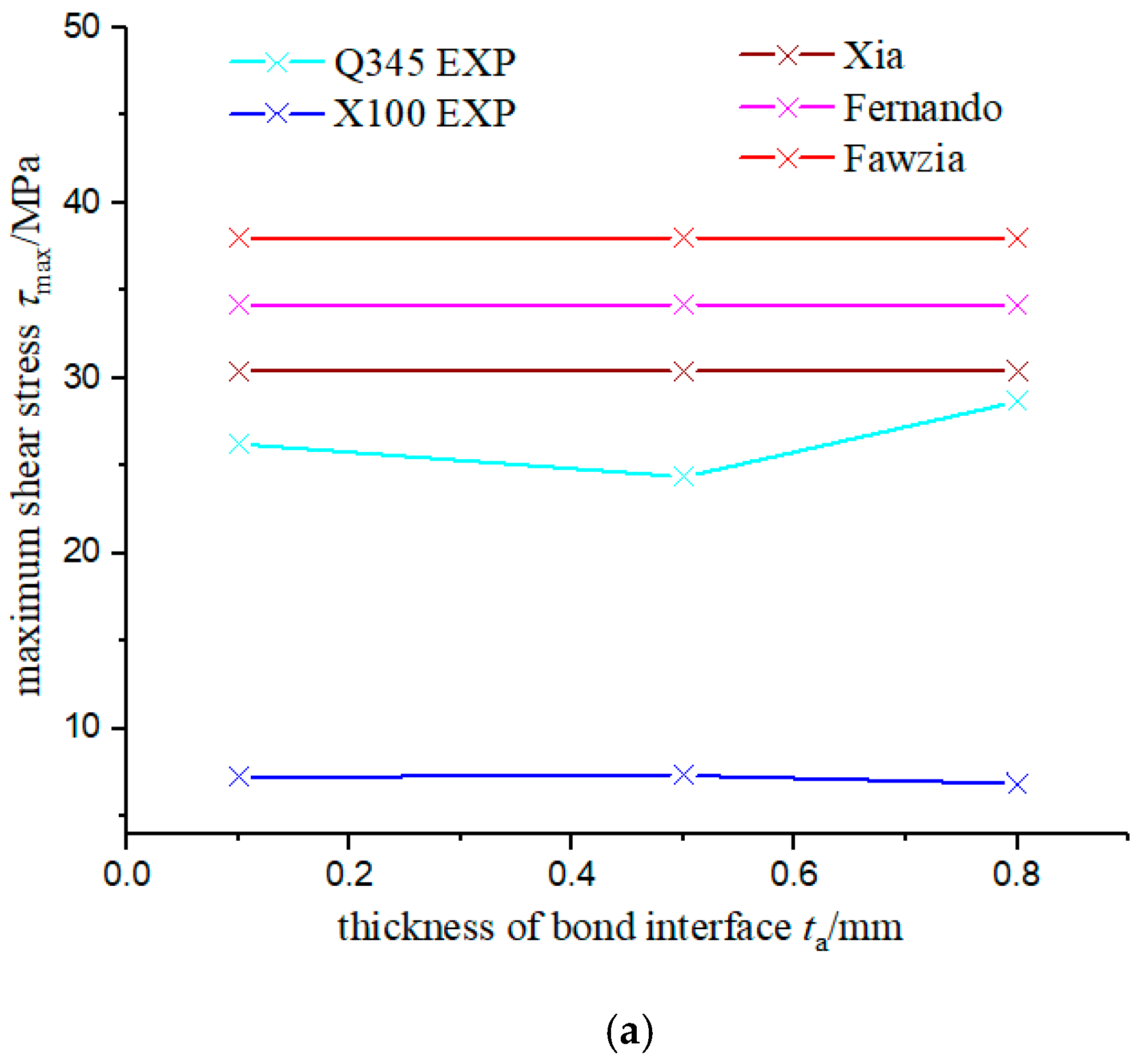
- The of the bonding interface of the CFRP-reinforced steel plate was not affected by the change in the thickness of the bonding interface, but the of the Q345B specimen was larger than that of the X100, about 1.9 times that of the X100. It may be because of the difference of surface roughness between two steel types. A steel plate with higher strength may decrease the bond property of the bond interface, which awaits further study.
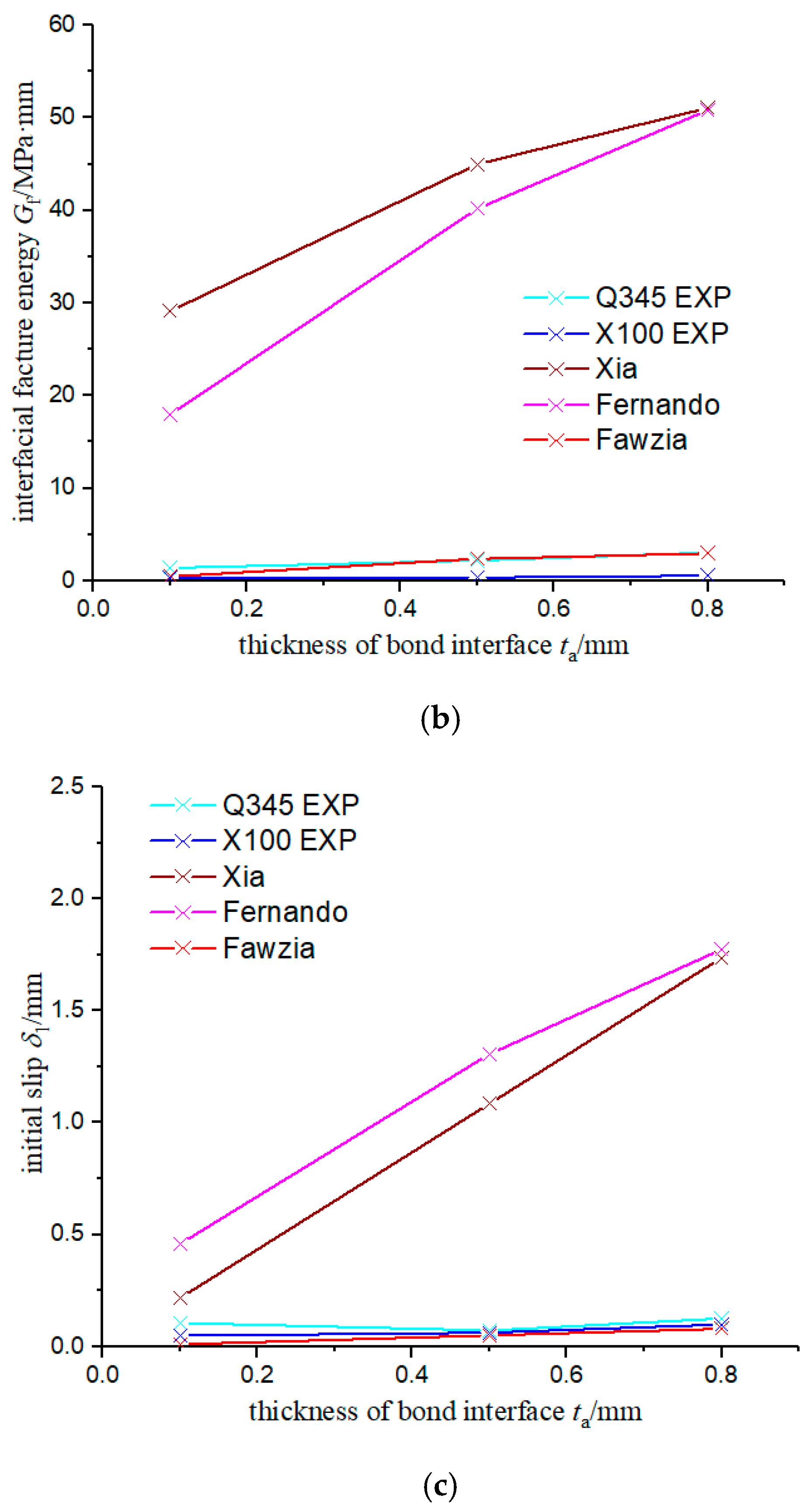
- The result of given by Xia’s model was the closest to the experimental result of Q345; for the and , Fawzia’s fitting results were the closest to the experimental results, but Xia’s model better predicted the trend in the thickness of the bonding interface on the bond–slip parameters. The initial facture energy of bonding interface is linear correlate with thickness of bonding interface, and initial slip is exponential correlated with thickness of bonding interface.
- An FE model for CFRP-strengthened steel was established; the model proved to be effective for the analysis of the bond characteristics of the CFRP–steel interface, for the total error between the numerical simulation results of the bond–slip curves and the test results was less than 10%. Furthermore, the introduction of the maximum stress criterion proved to be very helpful to the modeling of the bonding interface.
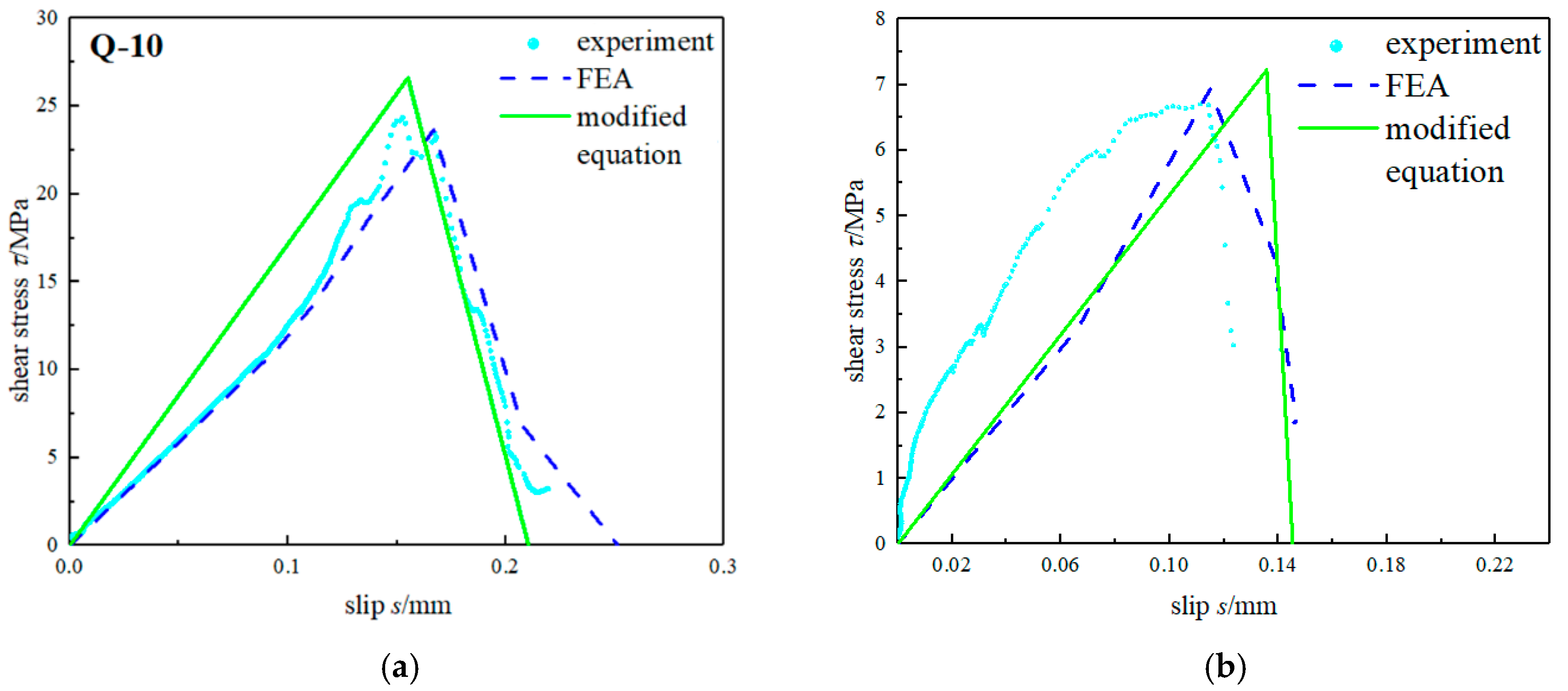
- A set of modified equations for the bond–slip parameters was given. The effectiveness of the modified equations for predicting the bond characteristics of the CFRP–steel interface was verified by means of a verification test and FE analysis. The modified equations have a good prediction effect on the property of bonding interface, and the FE model and modified equations established in this study can be extended to further research, such as fatigue performance, crack propagation, and mechanical property under the specific environment of CFRP-strengthened steel structures.
Author Contributions
Funding
Institutional Review Board Statement
Informed Consent Statement
Data Availability Statement
Conflicts of Interest
References
- Lu, Y.Y.; Huang, Y.S.; Zhang, H.J.; Liu, L. New Progress in the Study of the Technology of Reinforcement with Fober Reinforced Plastics. China Railw. Sci. 2006, 27, 34–42. [Google Scholar]
- Zhao, X.L.; Lei, Z. State-of-the-art review on FRP strengthened steel structures. Steel Constr. 2007, 29, 1808–1823. [Google Scholar] [CrossRef]
- Teng, J.G. New-meterial hybrid structures. China Civ. Eng. J. 2018, 51, 1–11. [Google Scholar]
- Yu, Z.H.; Hu, F.Y.; Cui, A.Y.; He, X.C.; Zhao, P.Z. Applied Research Progess of FRP Reinforced Metal Structure. Equip. Environ. Eng. 2018, 15, 24–31. [Google Scholar]
- Lu, X.Y. Research on welding residual stress of steel structure and welding deformation control technology. China High-Tech 2020, 40–41. [Google Scholar] [CrossRef]
- Zheng, Z.C.; Li, Y.Z.; Tang, L. Application of CFRP composite in strengthening and repairing engineering structures. Sichuan Archit. 2008, 28, 183–186. [Google Scholar]
- Zhang, J.X.; Jiang, S.C. State of the Art on FRP Strengthened Metal Structures. J. Civ. Eng. Manag. 2014, 31, 39–50. [Google Scholar]
- Miller, T.C.; Chajes, M.J.; Mertz, D.R.; Hastings, J.N. Strengthening of a steel bridge girder using CFRP plates. J. Bridge Eng. 2001, 6, 514–522. [Google Scholar] [CrossRef]
- Galvez, P.; Quesada, A.; Martinez, M.A.; Abenojar, J.; Boada, M.J.L.; Diaz, V. Study of the behaviour of adhesive joints of steel with CFRP for its application in bus structures. Compos. Part B 2017, 129, 41–46. [Google Scholar] [CrossRef]
- Marques, E.A.S.; da Silva, L.F.M.; Flaviani, M. Testing and simulation of mixed adhesive joints for aerospace applications. Compos. Part B 2015, 74, 123–130. [Google Scholar] [CrossRef]
- Al-Mosawe, A.; Al-Mahaidi, R.; Zhao, X.L. Effect of CFRP properties, on the bond characteristics between steel and CFRP laminate under quasi-static loading. Constr. Build. Mater. 2015, 98, 489–501. [Google Scholar] [CrossRef]
- He, J.; Xian, G. Debonding of CFRP-to-steel joints with CFRP delamination. Compos. Struct. 2016, 153, 12–20. [Google Scholar] [CrossRef]
- Yu, T.; Fernando, D.; Teng, J.G.; Zhao, X.L. Experimental study on CFRP-to-steel bonded interfaces. Compos. Part B: Eng. 2012, 43, 2279–2289. [Google Scholar] [CrossRef]
- Fawzia, S.; Zhao, X.L.; Al-Mahaidi, R. Bond–slip models for double strap joints strengthened by CFRP. Compos. Struct. 2010, 92, 2137–2145. [Google Scholar] [CrossRef] [Green Version]
- Wang, H.T.; Wu, G. Experimental study on the bond behavior of CFRP plate-steel interfaces. In Proceedings of the 9th National Symposium on FRP application in Construction Engineering, Chongqing, China, 15 May 2015. [Google Scholar]
- Majidi, H.R.; Razavi SM, J.; Berto, F. Failure assessment of steel/CFRP double strap joints. Metals 2017, 7, 255. [Google Scholar] [CrossRef] [Green Version]
- Li, C.X.; Ke, L.; He, J.; Chen, Z.; Jiao, Y. Effects of mechanical properties of adhesive and CFRP on the bond behavior in CFRP-strengthened steel structures. Compos. Struct. 2019, 211, 163–174. [Google Scholar] [CrossRef]
- Ke, L.; Li, C.X.; Luo, N.; He, J. Enhanced comprehensive performance of bonding interface between CFRP and steel by a novel film adhesive. Compos. Struct. 2019, 229, 111393. [Google Scholar] [CrossRef]
- Yang, Y.; Huang, Z.H.; Wu, Z.D. Study on bonding performance of CFRP-steel plate interface based on double shear test. J. Sun Yat-sen Univ. Nat. Sci. Ed. 2021, 60, 62–70. [Google Scholar]
- ASTM E8/E8M-16a; Standard Test Methods for Tension Testing of Metallic Materials. ASTM International: West Conshohocken, PA, USA, 2016.
- ASTM 3528-D96(2016); Standard Test Method for Strength Properties of Double Lap Shear Adhesive Joints by Tension Loading. ASTM: West Conshohocken, PA, USA, 2016.
- Tavakkolizadeh, M.; Saadatmanesh, H. Galvanic corrosion of carbon and steel in aggressive environments. J. Compos. Constr. 2001, 5, 200–210. [Google Scholar] [CrossRef]
- Xia, S.H.; Teng, J.G. Behaviour of FRP-to-steel bonded joints. In Proceedings of the International Symposium on Bond Behaviour of FRP in Structures (BBFS 2005), Hong Kong, China, 7–9 December 2005; pp. 419–426. [Google Scholar]
- Fernando Dilum, N. Bond Behaviour and Debonding Failures in Cfrp-Strengthened Steel Members. Ph.D. Thesis, Hong Kong Polytechnic University, Hong Kong, China, 2010. [Google Scholar]


| Elastic Modulus (GPa) | Poisson Ratio | Yield Strength (MPa) | Tensile Strength (MPa) | Shear Strength (MPa) | |
|---|---|---|---|---|---|
| Q345B | 206 | 0.3 | 345 | 455 | / |
| X100 | 210 | 0.3 | 700 | 790 | / |
| CFRP | 230 | 0.307 | / | 4750 | / |
| Lica-131 | 2.4 | / | / | 38 | 14 |
| Steel Type | Test Groups | Thickness of Bonding Interface (mm) | Sample |
|---|---|---|---|
| Q345B | Q-01 | 0.1 | 3 |
| Q-05 | 0.5 | 3 | |
| Q-08 | 0.8 | 3 | |
| X100 | X-01 | 0.1 | 3 |
| X-05 | 0.5 | 3 | |
| X-08 | 0.8 | 3 |
| Xia [23] | Fernando [24] | Fawzia [14] |
|---|---|---|
| Test Groups | EXP | FEA |
|---|---|---|
| Q-01 | 56.8 | 51.6 |
| Q-05 | 56.3 | 52.9 |
| Q-08 | 41.7 | 39.0 |
| X-01 | 25.3 | 28.9 |
| X-05 | 25.6 | 31.7 |
| X-08 | 18.8 | 25.4 |
Publisher’s Note: MDPI stays neutral with regard to jurisdictional claims in published maps and institutional affiliations. |
© 2022 by the authors. Licensee MDPI, Basel, Switzerland. This article is an open access article distributed under the terms and conditions of the Creative Commons Attribution (CC BY) license (https://creativecommons.org/licenses/by/4.0/).
Share and Cite
Guo, X.; Wu, Z.; Yang, Y.; Bai, J.; Zhou, Q. A Study on the Bond–Slip Relationship of the CFRP–Steel Interface of CFRP Strengthened Steel. Materials 2022, 15, 4187. https://doi.org/10.3390/ma15124187
Guo X, Wu Z, Yang Y, Bai J, Zhou Q. A Study on the Bond–Slip Relationship of the CFRP–Steel Interface of CFRP Strengthened Steel. Materials. 2022; 15(12):4187. https://doi.org/10.3390/ma15124187
Chicago/Turabian StyleGuo, Xinyan, Zuodong Wu, Yi Yang, Jiahao Bai, and Qianziyang Zhou. 2022. "A Study on the Bond–Slip Relationship of the CFRP–Steel Interface of CFRP Strengthened Steel" Materials 15, no. 12: 4187. https://doi.org/10.3390/ma15124187