
A Fully 3D-Printed Steerable Instrument for Minimally Invasive Surgery

 , ,
, ,
Abstract
:
1. Introduction
1.1. State of the Art
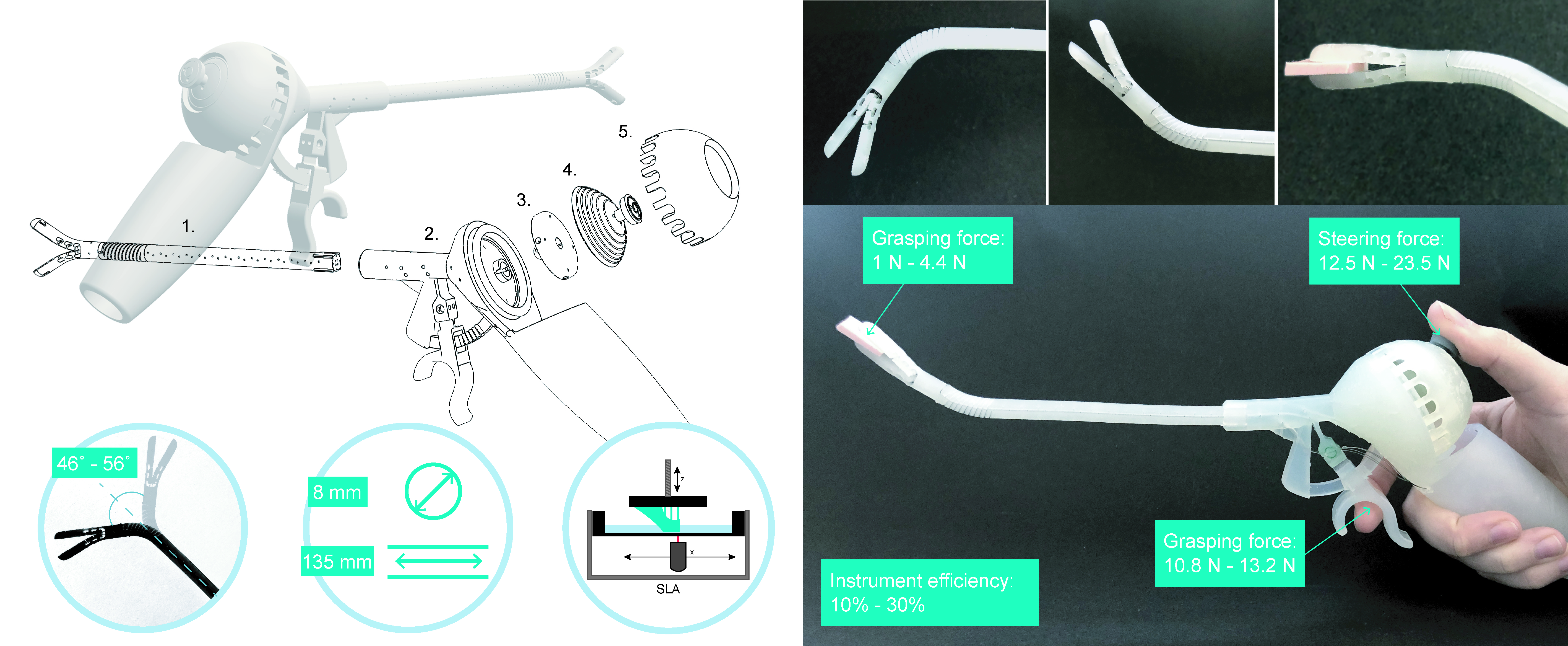
1.2. Challenges in Minimally Invasive Surgery
1.3. Additive Manufacturing for Surgical Devices
1.4. Objective and Requirements
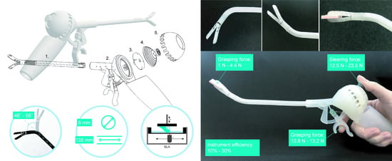
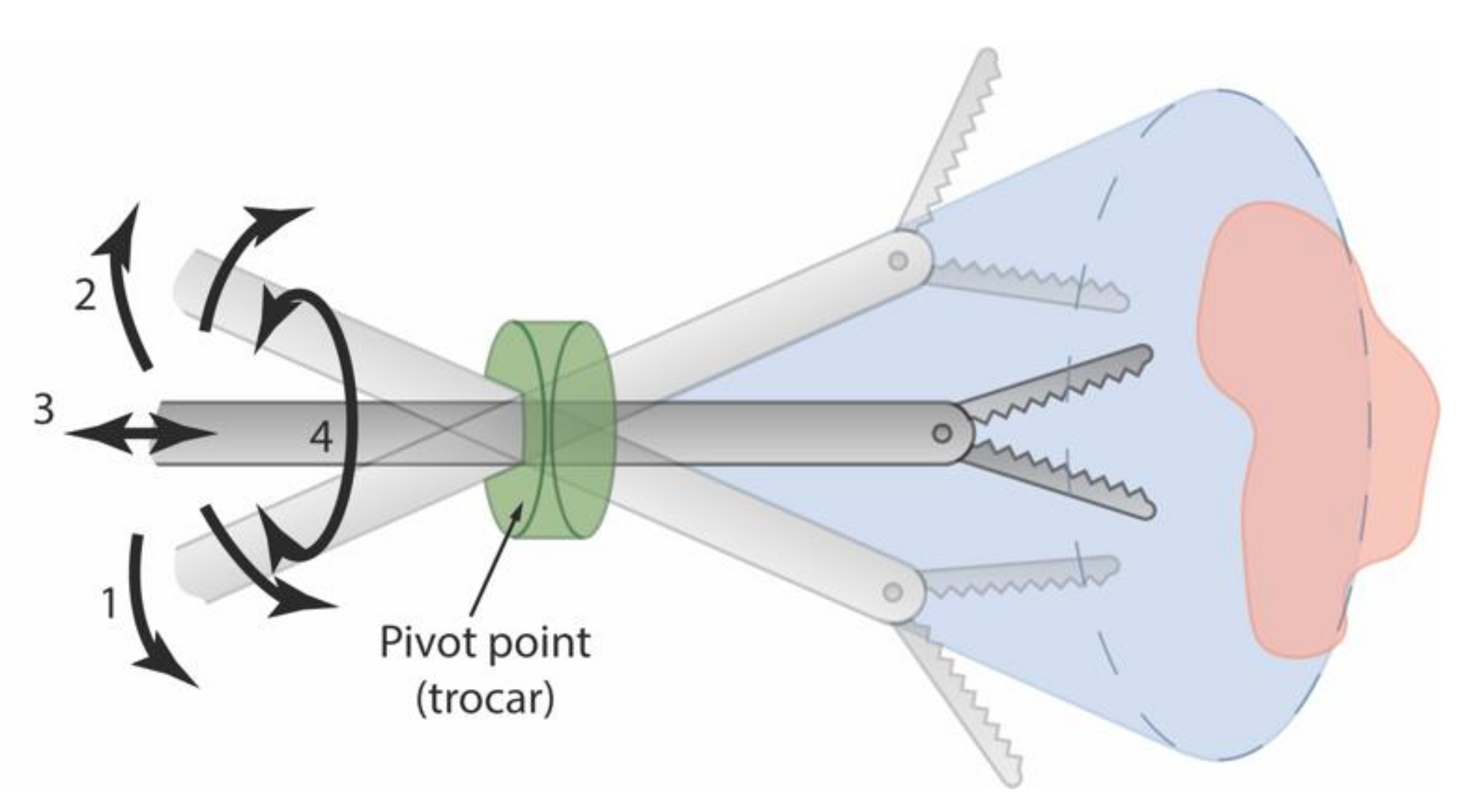
2. 3D-GriP Design
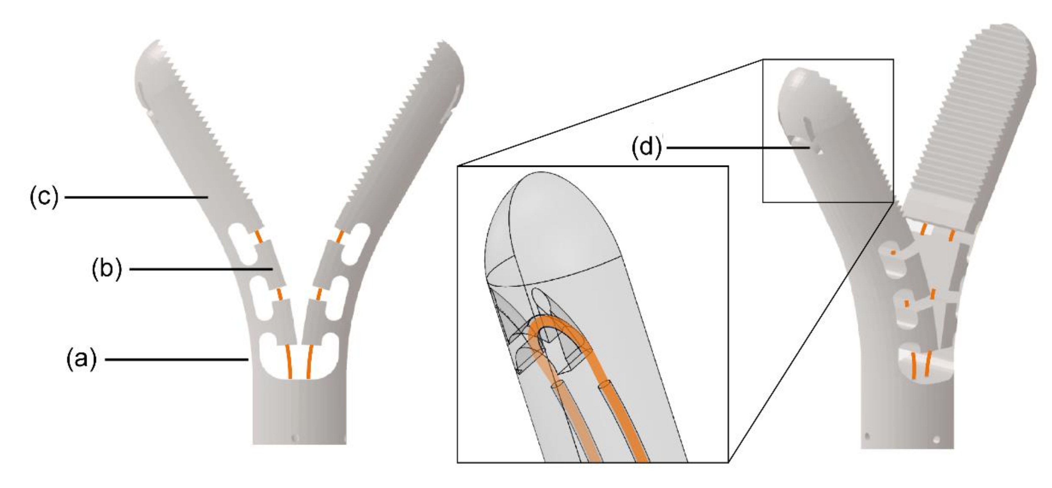
2.1. Gripper Design
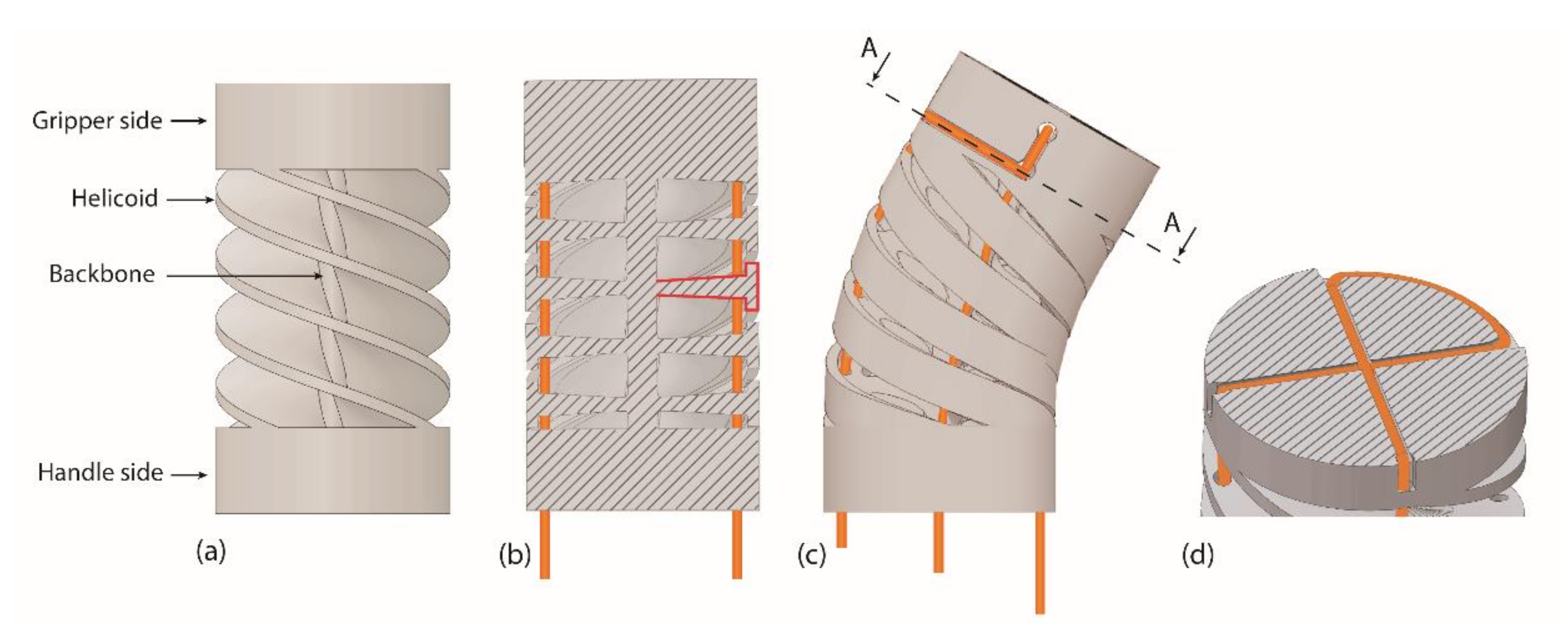
2.2. Steerable Segment Design
2.3. Handgrip Ergonomics
2.4. Steering Control
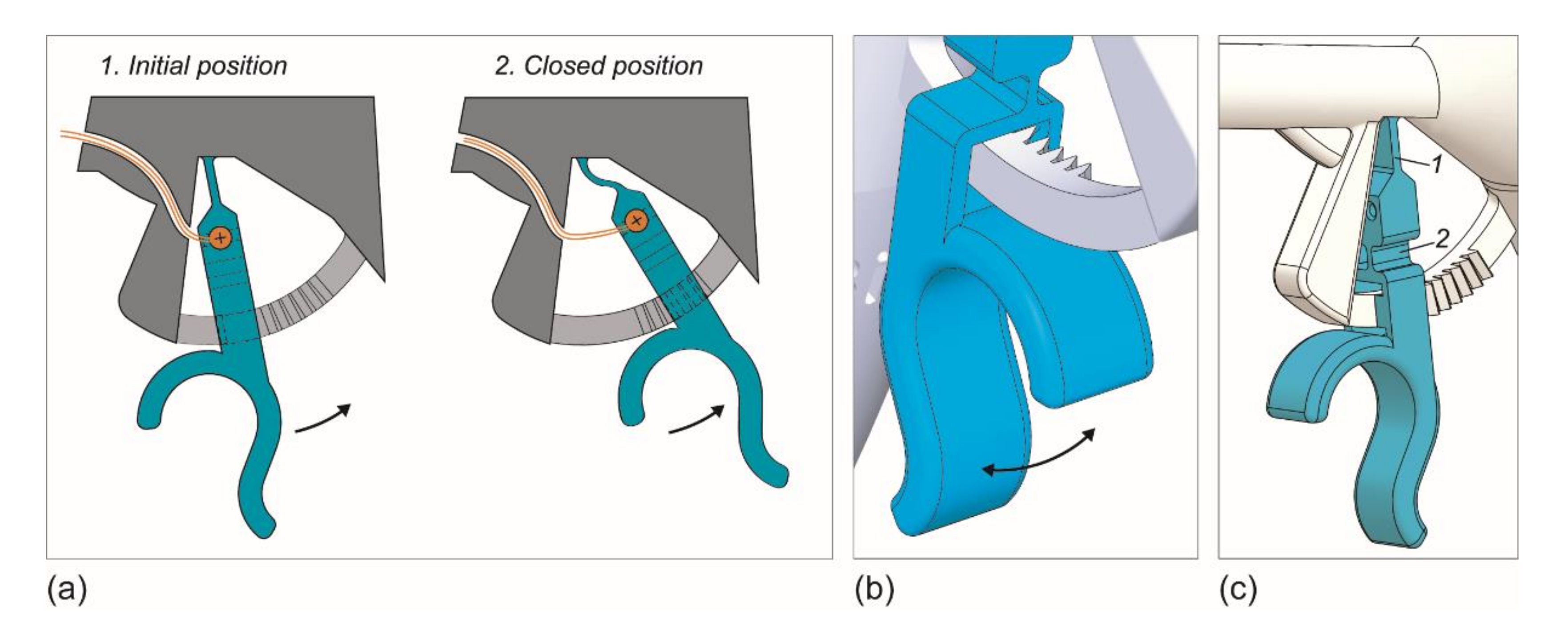
2.5. Gripper Control
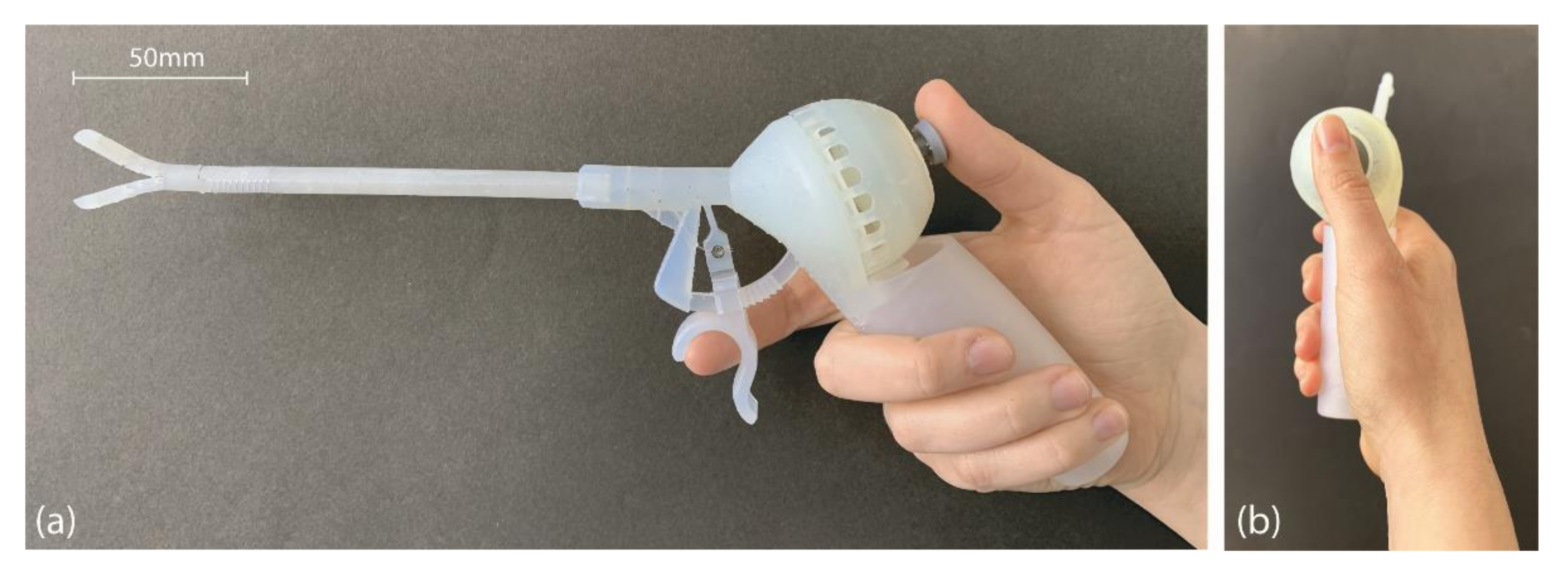
2.6. Prototype Fabrication and Assembly
3. Experimental Methods and Results
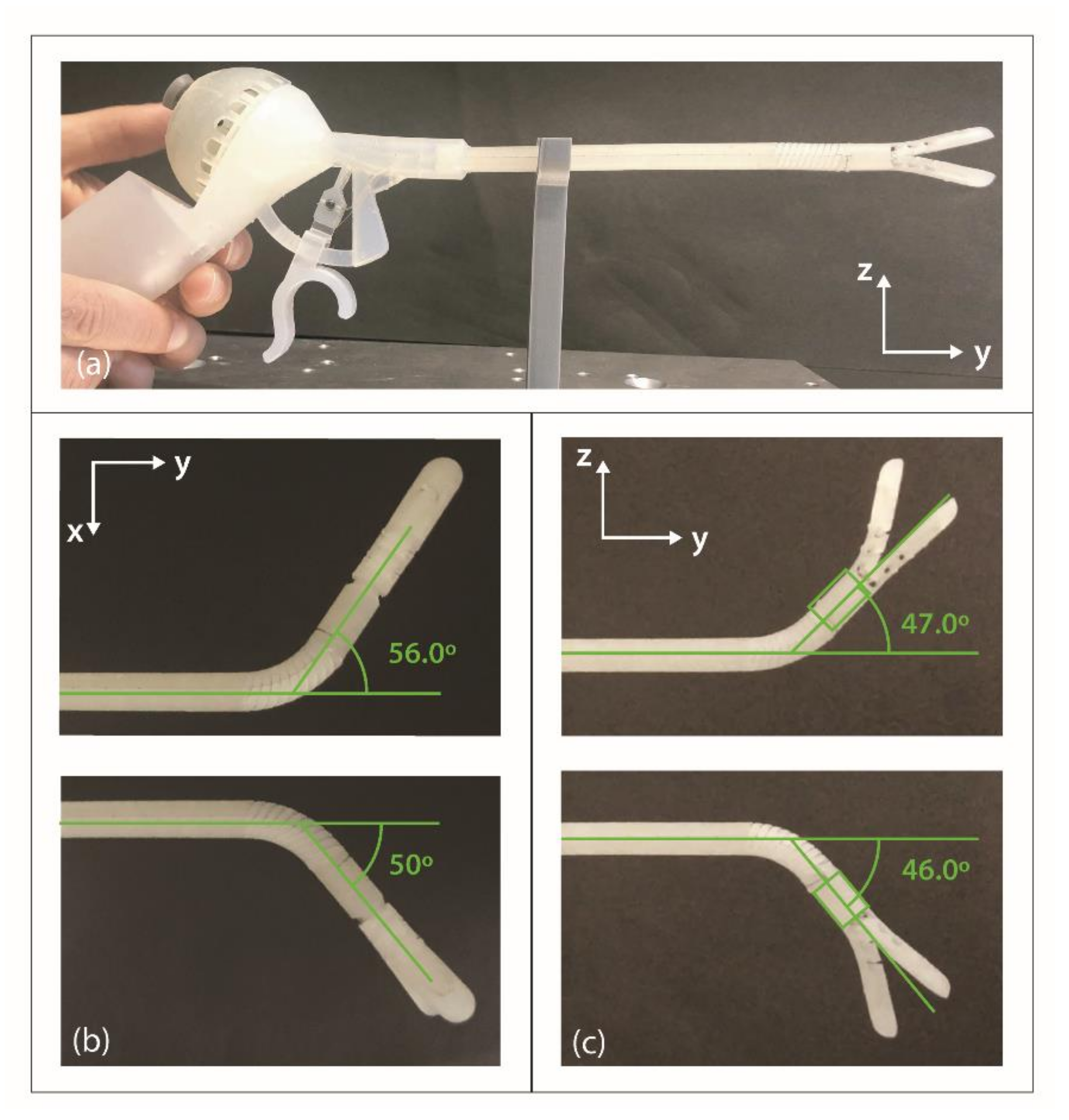
3.1. Bending Angle Measurements
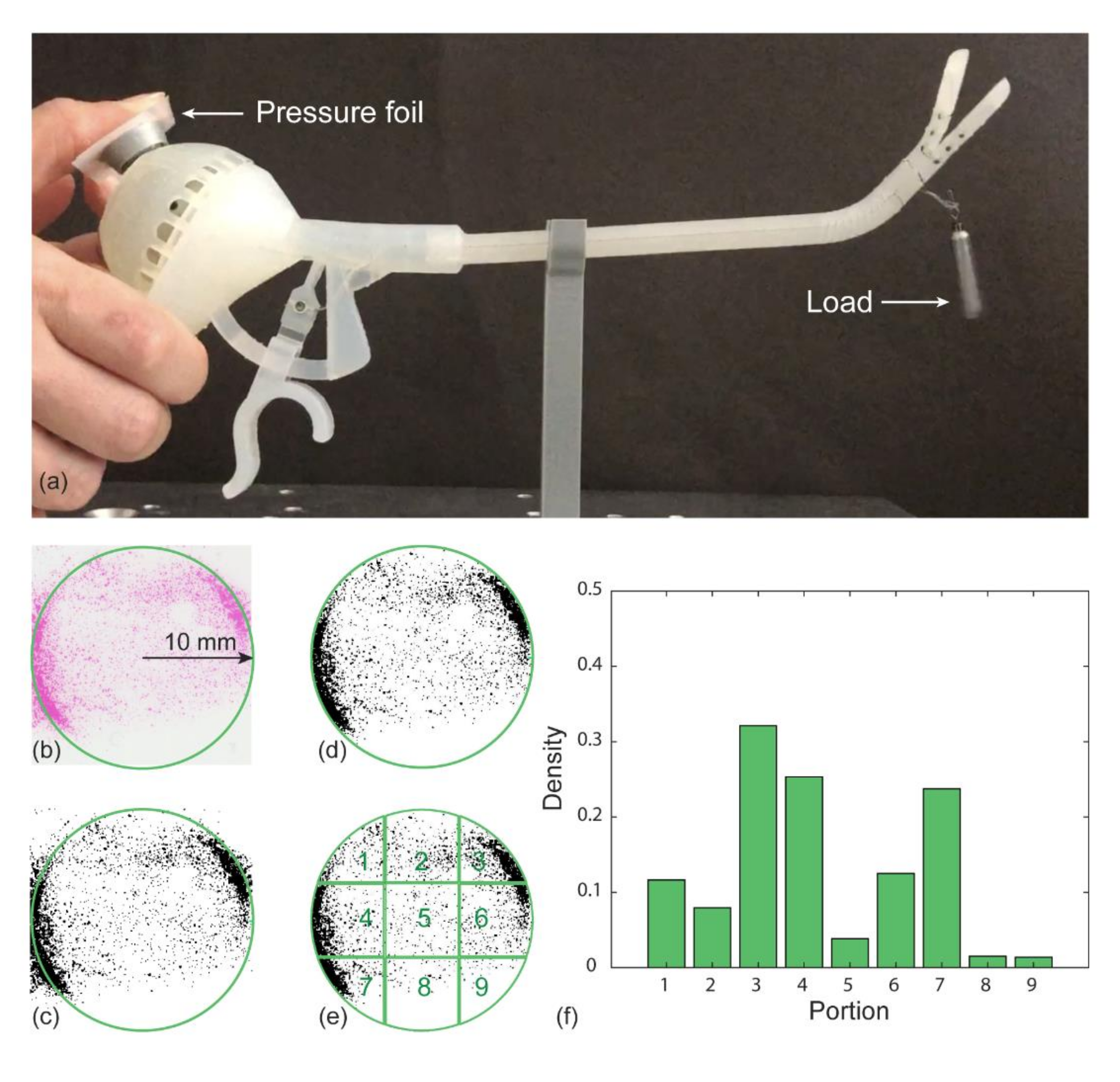
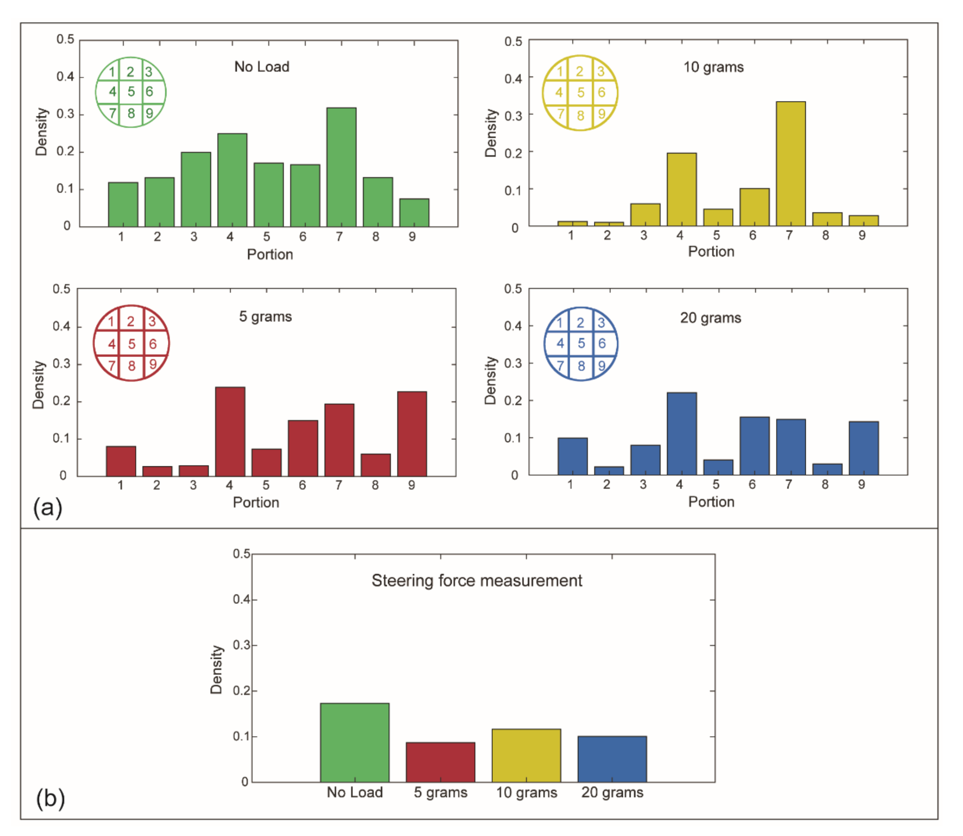
3.2. Steering Force Test
3.2.1. Method
3.2.2. Results
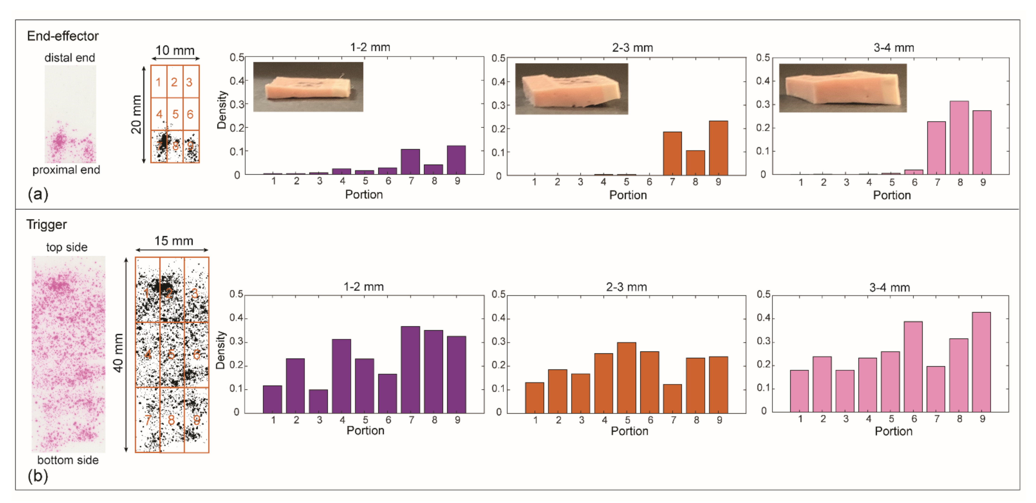
3.3. Grasping Force Test
3.3.1. Method
3.3.2. Results
4. Discussion
4.1. Production and Customization
4.2. Performance and Improvements
4.3. Limitations and Future Studies
5. Conclusions
Supplementary Materials
Author Contributions
Funding
Institutional Review Board Statement
Informed Consent Statement
Data Availability Statement
Conflicts of Interest
References
- Velanovich, V. Laparoscopic vs open surgery. Surg. Endosc. 2000, 14, 16–21. [Google Scholar] [CrossRef]
- Parisi, A.; Reim, D.; Borghi, F.; Nguyen, N.T.; Qi, F.; Coratti, A.; Cianchi, F.; Cesari, M.; Bazzocchi, F.; Alimoglu, O. Minimally invasive surgery for gastric cancer: A comparison between robotic, laparoscopic and open surgery. World J. Gastroenterol. 2017, 23, 2376. [Google Scholar] [CrossRef]
- Jelínek, F.; Pessers, R.; Breedveld, P. DragonFlex Smart Steerable Laparoscopic Instrument. J. Med. Device. 2014, 8, 015001–015009. [Google Scholar] [CrossRef]
- Prewitt, R.; Bochkarev, V.; McBride, C.L.; Kinney, S.; Oleynikov, D. The patterns and costs of the Da Vinci robotic surgery system in a large academic institution. J. Robot. Surg. 2008, 2, 17–20. [Google Scholar] [CrossRef]
- Anderson, P.L.; Lathrop, R.A.; Webster III, R.J. Robot-like dexterity without computers and motors: A review of hand-held laparoscopic instruments with wrist-like tip articulation. Expert Rev. Med. Devices 2016, 13, 661–672. [Google Scholar] [CrossRef] [PubMed]
- Anderson, P.L.; Lathrop, R.A.; Herrell, S.D.; Webster, R.J. Comparing a Mechanical Analogue With the Da Vinci User Interface: Suturing at Challenging Angles. IEEE Robot. Autom. Lett. 2016, 1, 1060–1065. [Google Scholar] [CrossRef]
- Arata, J.; Saito, Y.; Fujimoto, H. Outer shell type 2 DOF bending manipulator using spring-link mechanism for medical applications. In Proceedings of the 2010 IEEE International Conference on Robotics and Automation, Anchorage, AK, USA, 3–7 May 2010; pp. 1041–1046. [Google Scholar]
- Santos-Carreras, L.; Hagen, M.; Gassert, R.; Bleuler, H. Survey on surgical instrument handle design: Ergonomics and acceptance. Surg. Innov. 2012, 19, 50–59. [Google Scholar] [CrossRef] [PubMed]
- Sánchez-Margallo, F.M.; Sánchez-Margallo, J.A. Ergonomics in Laparoscopic Surgery. In Laparoscopic Surgery; InTech: London, UK, 2017; Available online: https://www.intechopen.com/chapters/52944 (accessed on 16 December 2021).
- Matern, U.; Waller, P. Instruments for minimally invasive surgery. Surg. Endosc. 1999, 13, 174–182. [Google Scholar] [CrossRef]
- Choi, S. A Review of the Ergonomic Issues in the Laparoscopic Operating Room. J. Healthc. Eng. 2012, 3, 587–604. [Google Scholar] [CrossRef]
- Emam, T.A.; Frank, T.G.; Hanna, G.B.; Cuschieri, A. Influence of handle design on the surgeon’s upper limb movements, muscle recruitment, and fatigue during endoscopic suturing. Surg. Endosc. 2001, 15, 667–672. [Google Scholar] [CrossRef] [PubMed]
- Park, A.; Lee, G.; Seagull, F.J.; Meenaghan, N.; Dexter, D. Patients Benefit While Surgeons Suffer: An Impending Epidemic. J. Am. Coll. Surg. 2010, 210, 306–313. [Google Scholar] [CrossRef]
- Goossens, R.H.M.; van Veelen, M.A. Assessment of ergonomics in laparoscopic surgery. Minim. Invasive Ther. Allied Technol. 2001, 10, 175–179. [Google Scholar] [CrossRef]
- Gonzalez, A.G.; Salgado, D.R.; Moruno, L.G. Optimisation of a laparoscopic tool handle dimension based on ergonomic analysis. Int. J. Ind. Ergon. 2015, 48, 16–24. [Google Scholar] [CrossRef]
- Kim, Y.; Cheng, S.S.; Desai, J.P. Towards the development of a spring-based continuum robot for neurosurgery. In Proceedings of the Medical Imaging 2015: Image-Guided Procedures Robotic Interventions, and Modeling, Orlando, FL, USA, 22–24 February 2015; Volume 9415, p. 94151Q. [Google Scholar] [CrossRef]
- Culmone, C.; Smit, G.; Breedveld, P. Additive manufacturing of medical instruments: A state-of-the-art review. Addit. Manuf. 2019, 27, 461–473. [Google Scholar] [CrossRef]
- Cuellar, J.S.; Smit, G.; Plettenburg, D.; Zadpoor, A. Additive manufacturing of non-assembly mechanisms. Addit. Manuf. 2018, 21, 150–158. [Google Scholar] [CrossRef]
- Lussenburg, K.; Sakes, A.; Breedveld, P. Design of non-assembly mechanisms: A state-of-the-art review. Addit. Manuf. 2021, 39, 101846. [Google Scholar] [CrossRef]
- Thomas, T.; Kalpathy Venkiteswaran, V.; Ananthasuresh, G.K.; Misra, S. Surgical Applications of Compliant Mechanisms-A Review. J. Mech. Robot. 2020, 13, 020801. [Google Scholar] [CrossRef]
- Cuellar, J.S.; Smit, G.; Zadpoor, A.; Breedveld, P. Ten guidelines for the design of non-assembly mechanisms: The case of 3D-printed prosthetic hands. Proc. Inst. Mech. Eng. Part H J. Eng. Med. 2018, 232, 962–971. [Google Scholar] [CrossRef]
- Sun, Y.; Liu, Y.; Xu, L.; Zou, Y.; Faragasso, A.; Lueth, T.C. Automatic design of compliant surgical forceps with adaptive grasping functions. IEEE Robot. Autom. Lett. 2020, 5, 1095–1102. [Google Scholar] [CrossRef]
- Gibson, I.; Rosen, D.W.; Stucker, B. Additive Manufacturing Technologies; Springer: New York, NY, USA, 2010. [Google Scholar]
- Toth, L.; Schiffer, A.; Nyitrai, M.; Pentek, A.; Told, R.; Maroti, P. Developing an anti-spastic orthosis for daily home-use of stroke patients using smart memory alloys and 3D printing technologies. Mater. Des. 2020, 195, 109029. [Google Scholar] [CrossRef]
- Sreekanth, M.P.; Ranganathan, R.; Pugalendhi, A. Individual customization strategy accomplished by developing prototype of a laparoscopic forceps handle using additive manufacturing. Rapid Prototyp. J. 2020, 26, 689–697. [Google Scholar] [CrossRef]
- González, A.; Salgado, D.; García Moruno, L.; Sánchez Ríos, A. An Ergonomic Customized-Tool Handle Design for Precision Tools using Additive Manufacturing: A Case Study. Appl. Sci. 2018, 8, 1200. [Google Scholar] [CrossRef]
- González, A.G.; Barrios-Muriel, J.; Romero-Sánchez, F.; Salgado, D.R.; Alonso, F.J. Ergonomic assessment of a new hand tool design for laparoscopic surgery based on surgeons’ muscular activity. Appl. Ergon. 2020, 88, 103161. [Google Scholar] [CrossRef] [PubMed]
- Sánchez-Margallo, J.A.; González González, A.; García Moruno, L.; Gómez-Blanco, J.C.; Pagador, J.B.; Sánchez-Margallo, F.M. Comparative Study of the Use of Different Sizes of an Ergonomic Instrument Handle for Laparoscopic Surgery. Appl. Sci. 2020, 10, 1526. [Google Scholar] [CrossRef]
- Sánchez-Margallo, F.M.; Sánchez-Margallo, J.A.; Szold, A. Handheld Devices for Laparoscopic Surgery. In New Horizons in Laparoscopic Surgery; InTech Open: London, UK, 2018; pp. 75–93. [Google Scholar] [CrossRef]
- DEAM LaparoFlex Steerable Laparoscopic Instrument. Available online: https://www.deam.com/ (accessed on 16 December 2021).
- Zhu, R.; Maréchal, M.; Yamamoto, I.; Lawn, M.J.; Nagayasu, T.; Matsumoto, K. Evaluation of laparoscopic forceps jaw contact pressure and distribution using pressure sensitive film. Comput. Assist. Surg. 2019, 24, 105–116. [Google Scholar] [CrossRef]
- Schneider, A.; Feussner, H. Chapter 7—Operative (Surgical) Laparoscopy. Schneider, A., Feussner, H., Eds.; Academic Press: Cambridge, MA, USA, 2017; pp. 269–327. ISBN 978-0-12-803230-5. [Google Scholar]
- Howell, L.L. Compliant mechanisms. In 21st Century Kinematics; Springer: Berlin/Heidelberg, Germany, 2013; pp. 189–216. [Google Scholar]
- Lassooij, J.; Tolou, N.; Tortora, G.; Caccavaro, S.; Menciassi, A.; Herder, J.L. A statically balanced and bi-stable compliant end effector combined with a laparoscopic 2DoF robotic arm. Mech. Sci. 2012, 3, 85–93. [Google Scholar] [CrossRef]
- Dearden, J.; Grames, C.; Jensen, B.D.; Magleby, S.P.; Howell, L.L. Inverted L-Arm gripper compliant mechanism. J. Med. Device. 2017, 11, 034502. [Google Scholar] [CrossRef]
- Kota, S.; Lu, K.-J.; Kreiner, Z.; Trease, B.; Arenas, J.; Geiger, J. Design and application of compliant mechanisms for surgical tools. J. Biomech. Eng. 2005, 127, 981–989. [Google Scholar] [CrossRef]
- Chen, H.; Zhang, L.; Zhang, D.; Zhang, P.; Han, Z. Bioinspired surface for surgical graspers based on the strong wet friction of tree frog toe pads. ACS Appl. Mater. Interfaces 2015, 7, 13987–13995. [Google Scholar] [CrossRef]
- Culmone, C.; Henselmans, P.W.J.; van Starkenburg, R.I.B.; Breedveld, P. Exploring non-assembly 3D printing for novel compliant surgical devices. PLoS ONE 2020, 15, e0232952. [Google Scholar] [CrossRef] [PubMed]
- Tung, K.D.; Shorti, R.M.; Downey, E.C.; Bloswick, D.S.; Merryweather, A.S. The effect of ergonomic laparoscopic tool handle design on performance and efficiency. Surg. Endosc. 2015, 29, 2500–2505. [Google Scholar] [CrossRef] [PubMed]
- Okken, L.M.; Chmarra, M.K.; Hiemstra, E.; Jansen, F.W.; Dankelman, J. Assessment of joystick and wrist control in hand-held articulated laparoscopic prototypes. Surg. Endosc. 2012, 26, 1977–1985. [Google Scholar] [CrossRef]
- Fan, C.; Clogenson, H.; Breedveld, P.; van den Dobbelsteen, J.J.; Dankelman, J. Comparison of two control methods for minimally invasive surgical instruments. J. Med. Device 2012, 6, 021005. [Google Scholar] [CrossRef]
- Van Veelen, M.A.; Meijer, D.W.; Uijttewaal, I.; Goossens, R.H.M.; Snijders, C.J.; Kazemier, G. Improvement of the laparoscopic needle holder based on new ergonomic guidelines. Surg. Endosc. Other Interv. Tech. 2003, 17, 699–703. [Google Scholar] [CrossRef]
- Fan, C.; Dodou, D.; Breedveld, P. Review of manual control methods for handheld maneuverable instruments. Minim. Invasive Ther. Allied Technol. 2013, 22, 127–135. [Google Scholar] [CrossRef]
- Van Veelen, M.A.; Meijer, D.W.; Goossens, R.H.M.; Snijders, C.J. New Ergonomic Design Criteria for Handles of Laparoscopic Dissection Forceps. J. Laparoendosc. Adv. Surg. Tech. 2002, 11, 17–26. [Google Scholar] [CrossRef]
- Alvin, R.; Tilley, H.D.A. The Measure of Man and Woman: Human Factors in Design, Revised Edition; John Wiley & Sons: New York, NY, USA, 1994; ISBN 978-0-471-09955-0. [Google Scholar]
- Gardan, J. Additive manufacturing technologies: State of the art and trends. Int. J. Prod. Res. 2016, 54, 3118–3132. [Google Scholar] [CrossRef]
- Van Assenbergh, P.; Culmone, C.; Breedveld, P.; Dodou, D. Implementation of anisotropic soft pads in a surgical gripper for secure and gentle grip on vulnerable tissues. Proc. Inst. Mech. Eng. Part H J. Eng. Med. 2020, 235, 255–263. [Google Scholar] [CrossRef] [PubMed]
- Heijnsdijk, E.A.M.; Pasdeloup, A.; Dankelman, J.; Gouma, D.J. The optimal mechanical efficiency of laparoscopic forceps. Surg. Endosc. 2004, 18, 1766–1770. [Google Scholar] [CrossRef]
- Westebring-van der Putten, E.P.; van den Dobbelsteen, J.J.; Goossens, R.H.M.; Jakimowicz, J.J.; Dankelman, J. Effect of laparoscopic grasper force transmission ratio on grasp control. Surg. Endosc. 2009, 23, 818–824. [Google Scholar] [CrossRef] [PubMed]
- Berguer, R.; Gerber, S.; Kilpatrick, G. An ergonomic comparison of in-line vs pistol-grip handle configuration in a laparoscopic grasper. Surg. Endosc. 1998, 12, 805–808. [Google Scholar] [CrossRef] [PubMed]
- Sjoerdsma, W.; Herder, J.L.; Horward, M.J.; Jansen, A.; Bannenberg, J.J.G.; Grimbergen, C.A. Force transmission of laparoscopic grasping instruments. Minim. Invasive Ther. Allied Technol. 1997, 6, 274–278. [Google Scholar] [CrossRef]
- Herder, J.L.; Horward, M.J.; Sjoerdsma, W. A laparoscopic grasper with force perception. Minim. Invasive Ther. Allied Technol. 1997, 6, 279–286. [Google Scholar] [CrossRef]
- Jin, X.; Zhao, J.; Feng, M.; Hao, L.; Li, Q. Snake-like surgical forceps for robot-assisted minimally invasive surgery. Int. J. Med. Robot. Comput. Assist. Surg. 2018, 14, e1908. [Google Scholar] [CrossRef] [PubMed]


| No Load (Degrees) | 5 g (Degrees) | 10 g (Degrees) | 20 g (Degrees) | |||||
|---|---|---|---|---|---|---|---|---|
| Upward | Downward | Upward | Downward | Upward | Downward | Upward | Downward | |
| rep. 1 | 47.0 | 46.0 | 42.3 | 51.2 | 40.4 | 49.7 | 37.0 | 45.5 |
| rep. 2 | 46.2 | 48.7 | 43.7 | 50.3 | 35.8 | 52.2 | 34.3 | 50.8 |
| rep. 3 | 46.5 | 53.4 | 43.9 | 50.6 | 36.1 | 49.5 | 28.7 | 52.3 |
| Aver. | 46.6 ± 0.3 | 49.4 ± 3.8 | 43.3 ± 0.9 | 50.7 ± 0.5 | 37.4 ± 2.5 | 50.4 ± 1.5 | 33.3 ± 4.3 | 49.5 ± 3.5 |
Publisher’s Note: MDPI stays neutral with regard to jurisdictional claims in published maps and institutional affiliations. |
© 2021 by the authors. Licensee MDPI, Basel, Switzerland. This article is an open access article distributed under the terms and conditions of the Creative Commons Attribution (CC BY) license (https://creativecommons.org/licenses/by/4.0/).
Share and Cite
Culmone, C.; Lussenburg, K.; Alkemade, J.; Smit, G.; Sakes, A.; Breedveld, P. A Fully 3D-Printed Steerable Instrument for Minimally Invasive Surgery. Materials 2021, 14, 7910. https://doi.org/10.3390/ma14247910
Culmone C, Lussenburg K, Alkemade J, Smit G, Sakes A, Breedveld P. A Fully 3D-Printed Steerable Instrument for Minimally Invasive Surgery. Materials. 2021; 14(24):7910. https://doi.org/10.3390/ma14247910
Chicago/Turabian StyleCulmone, Costanza, Kirsten Lussenburg, Joost Alkemade, Gerwin Smit, Aimée Sakes, and Paul Breedveld. 2021. "A Fully 3D-Printed Steerable Instrument for Minimally Invasive Surgery" Materials 14, no. 24: 7910. https://doi.org/10.3390/ma14247910