
Influence of Degradation Product Thickness on the Elastic Stiffness of Porous Absorbable Scaffolds Made from an Bioabsorbable Zn–Mg Alloy

 , , , and
Abstract
:1. Introduction
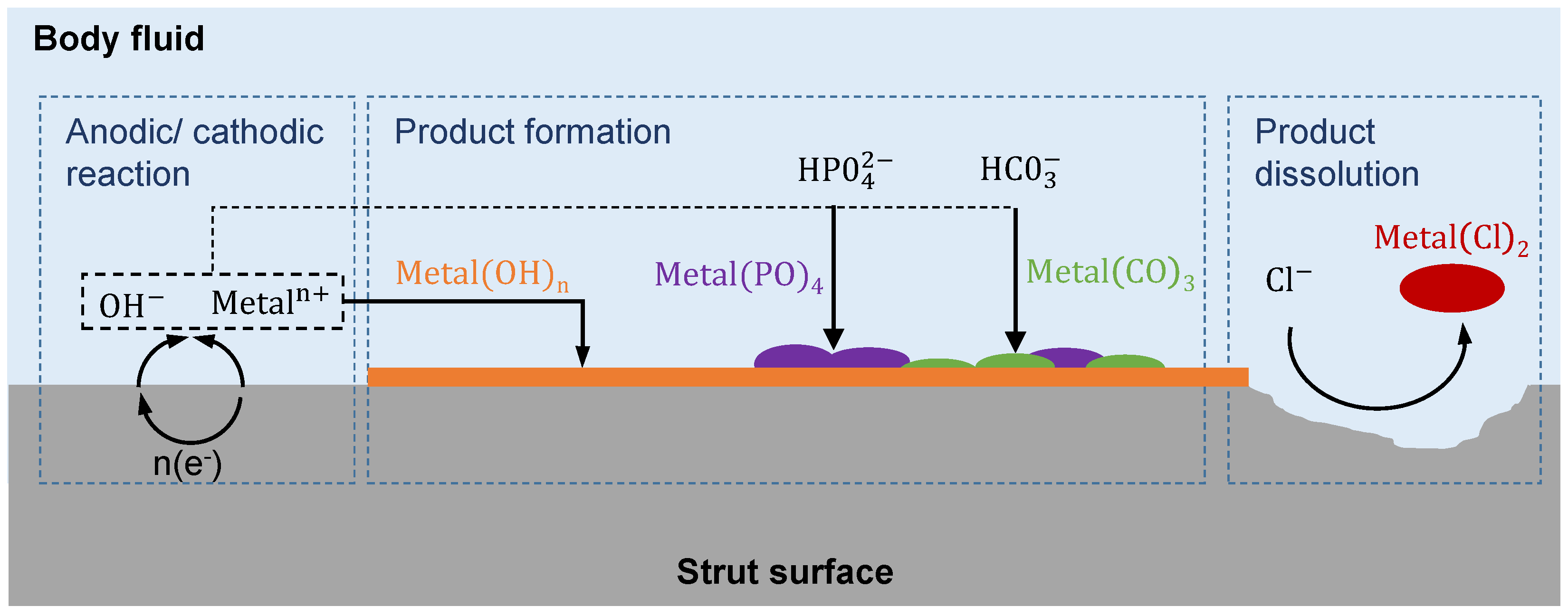
| Anodic reaction | |
| Cathodic reaction | |
| Product formation | |
| Product dissolution |
2. Materials and Methods
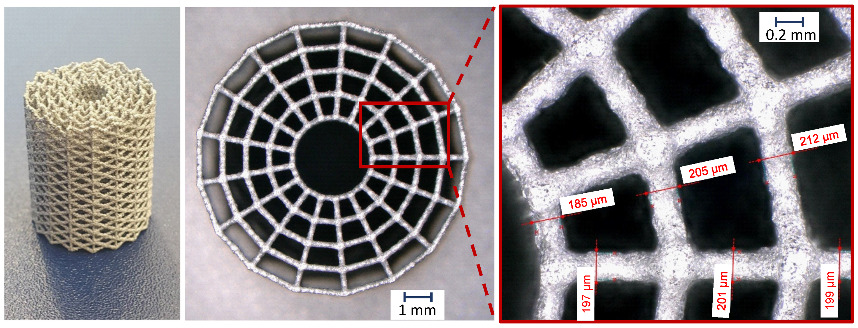
2.1. Scaffold Manufacturing
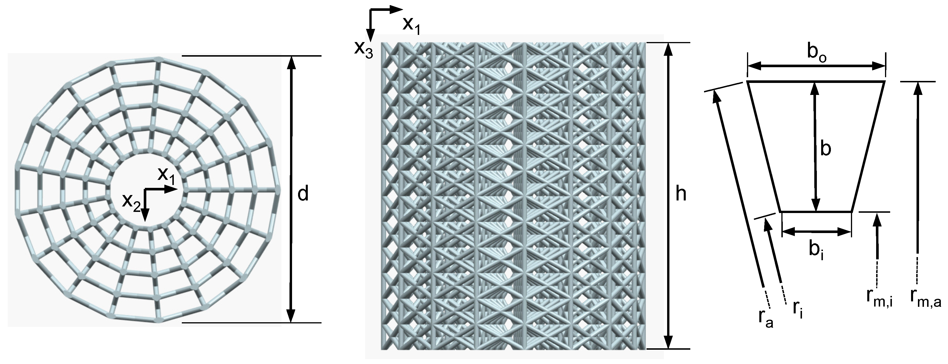
2.2. Scaffold Geometry
2.3. Materials and Mechanical Properties
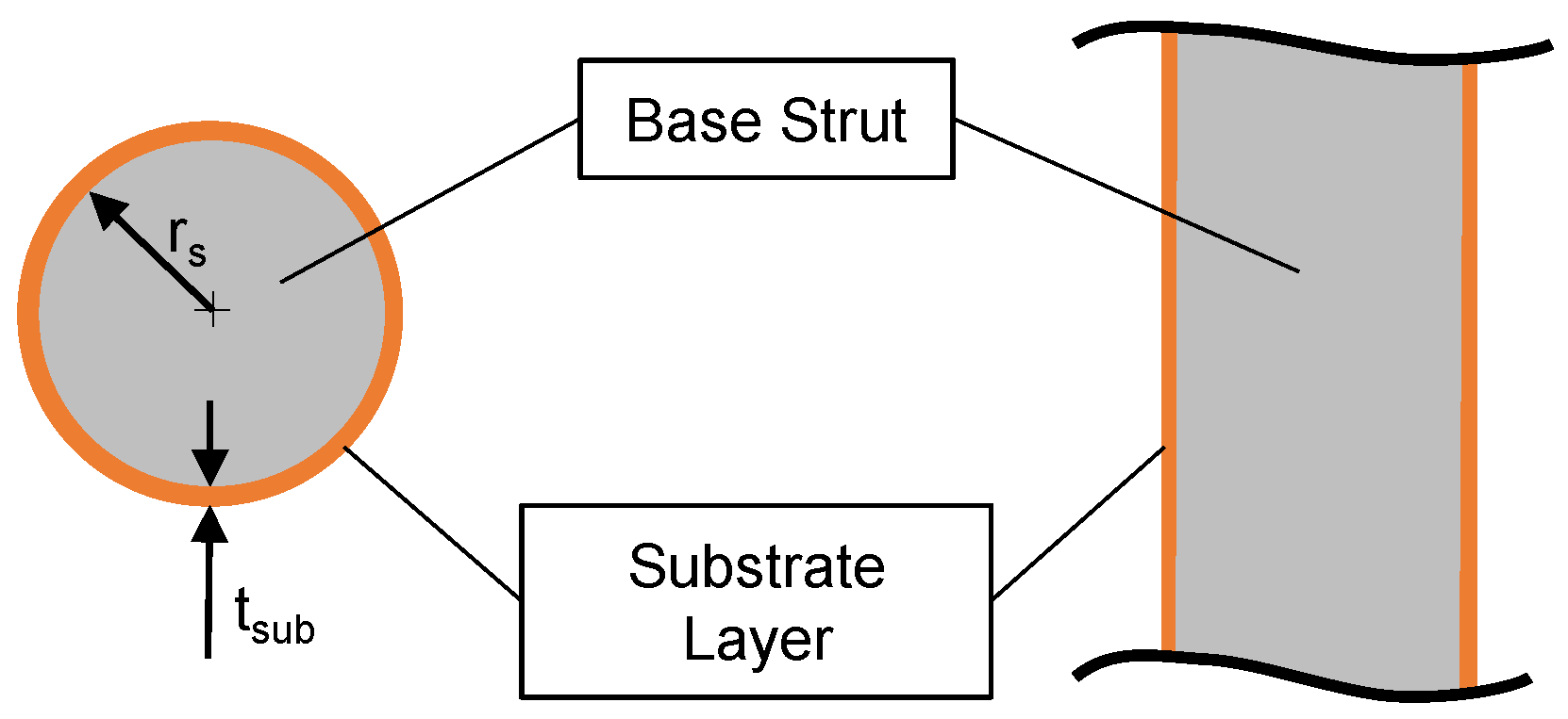
2.4. Analytical Model
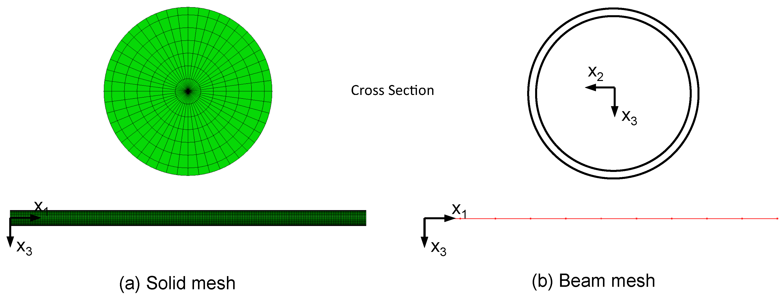
2.5. Finite-Element Model
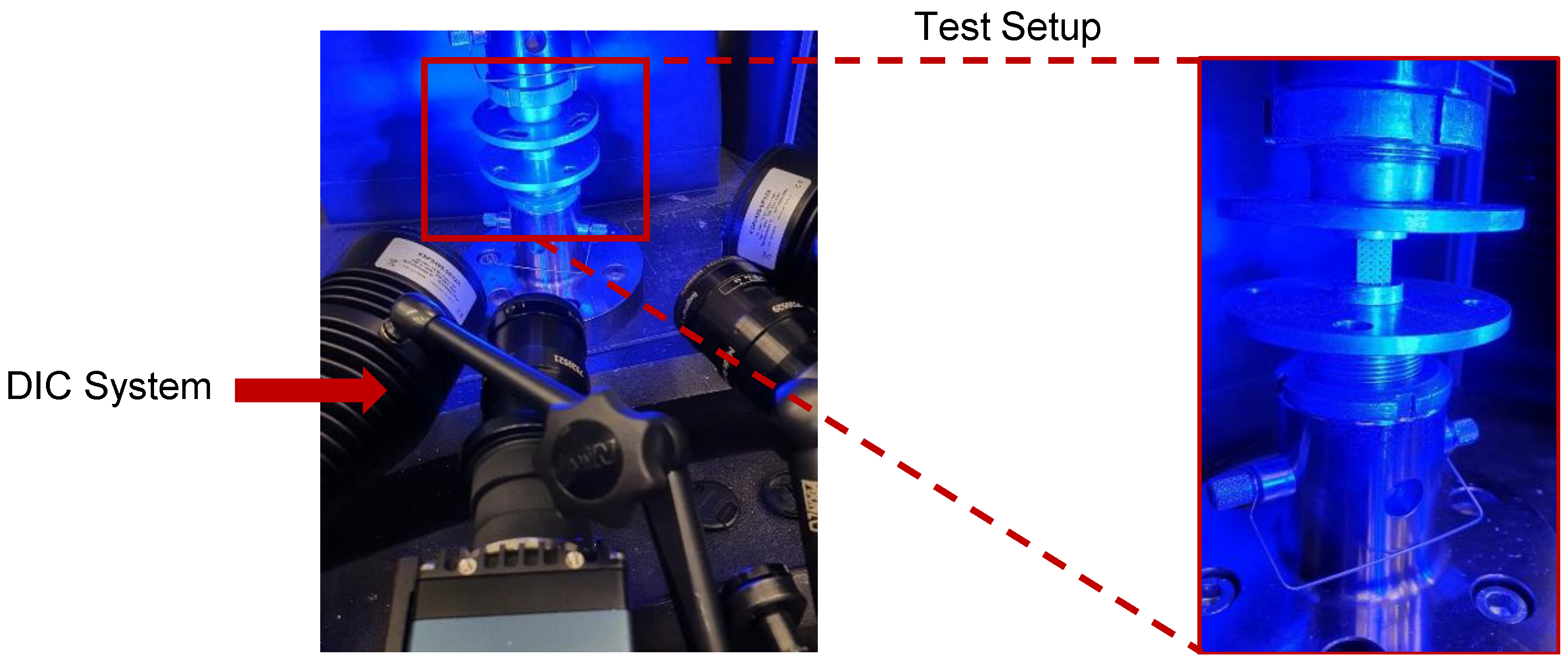
2.6. Compression Testing
3. Results
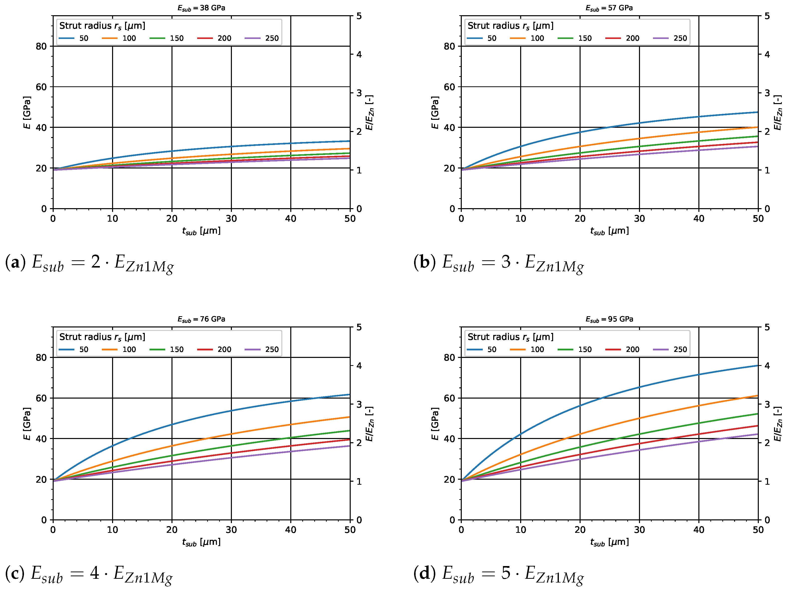
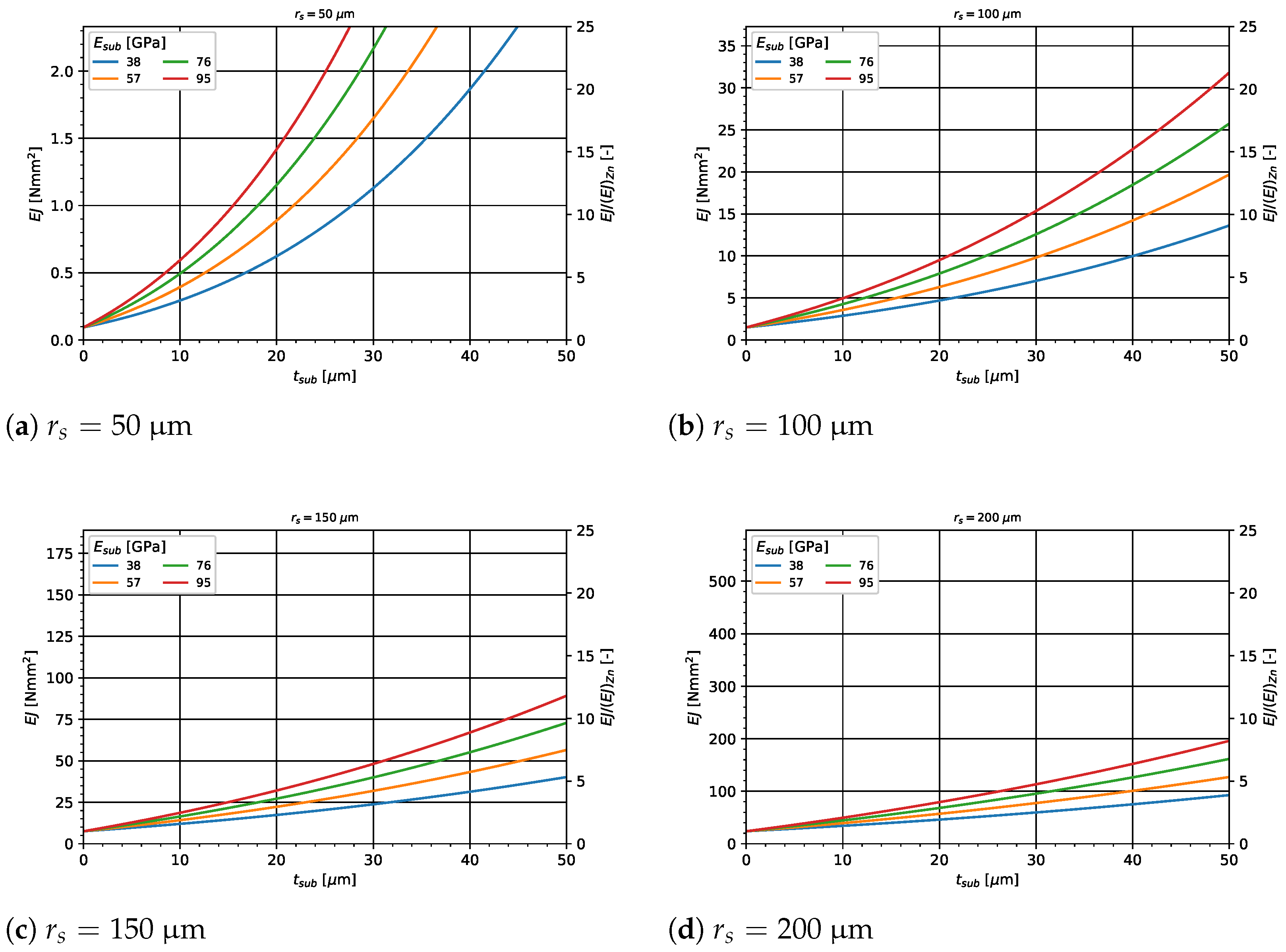
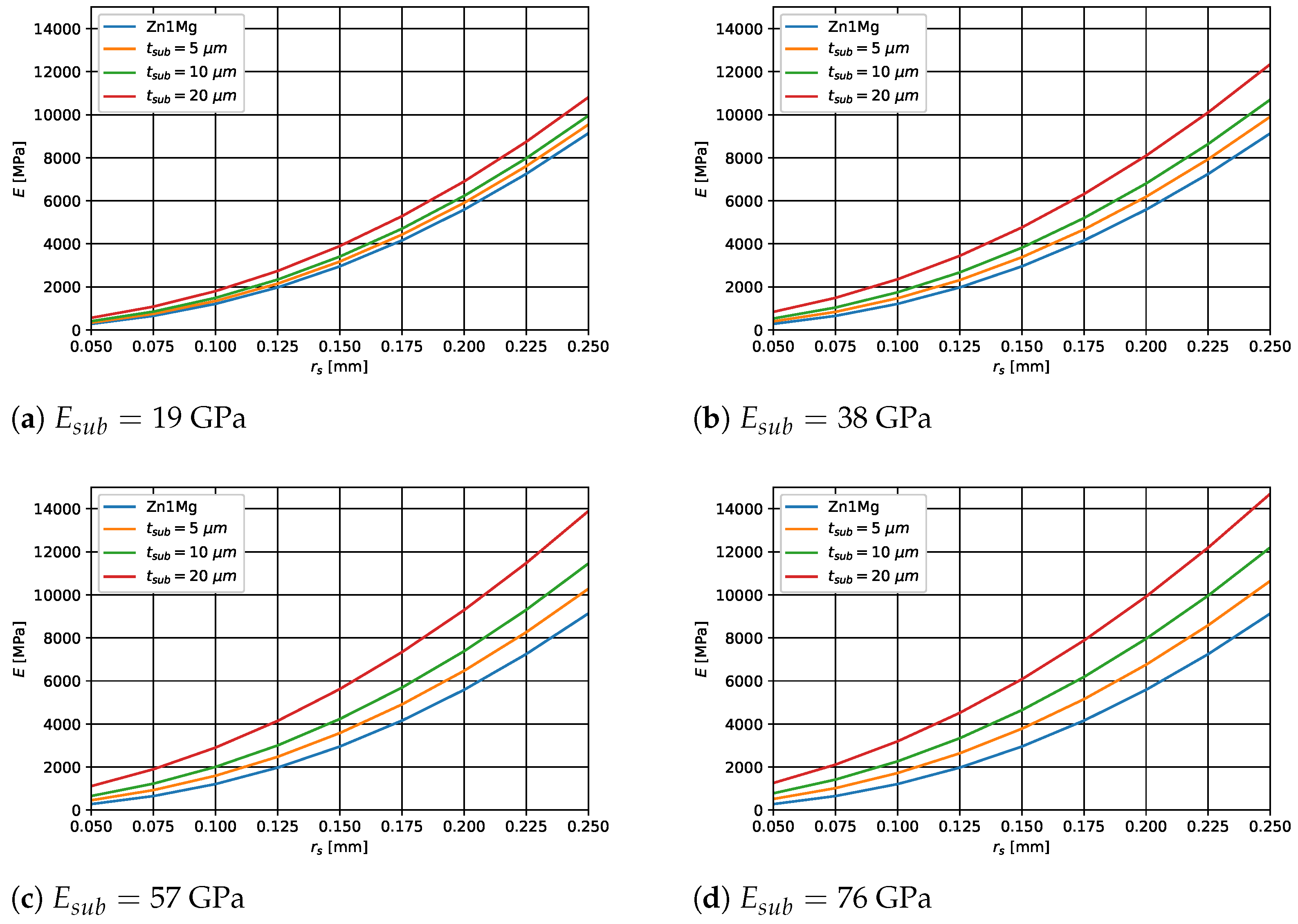
3.1. Analytical Results
3.2. Finite-Element Results
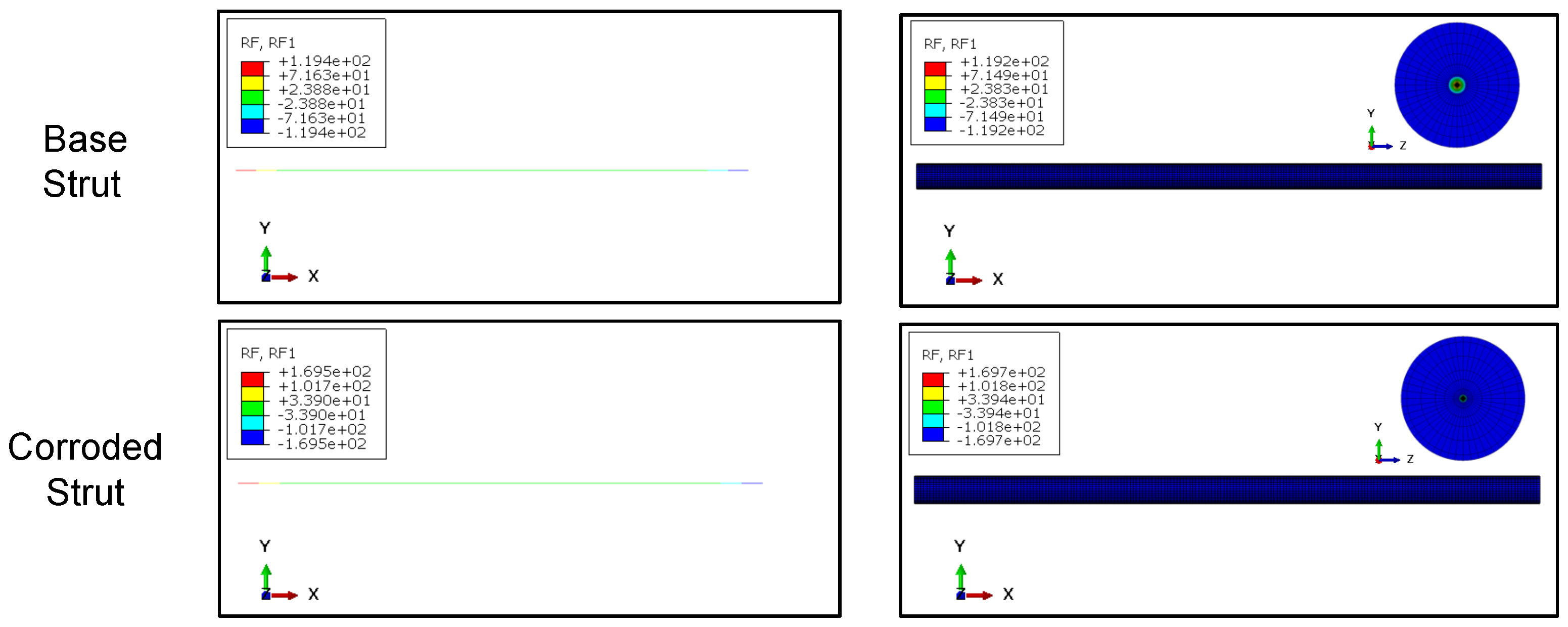
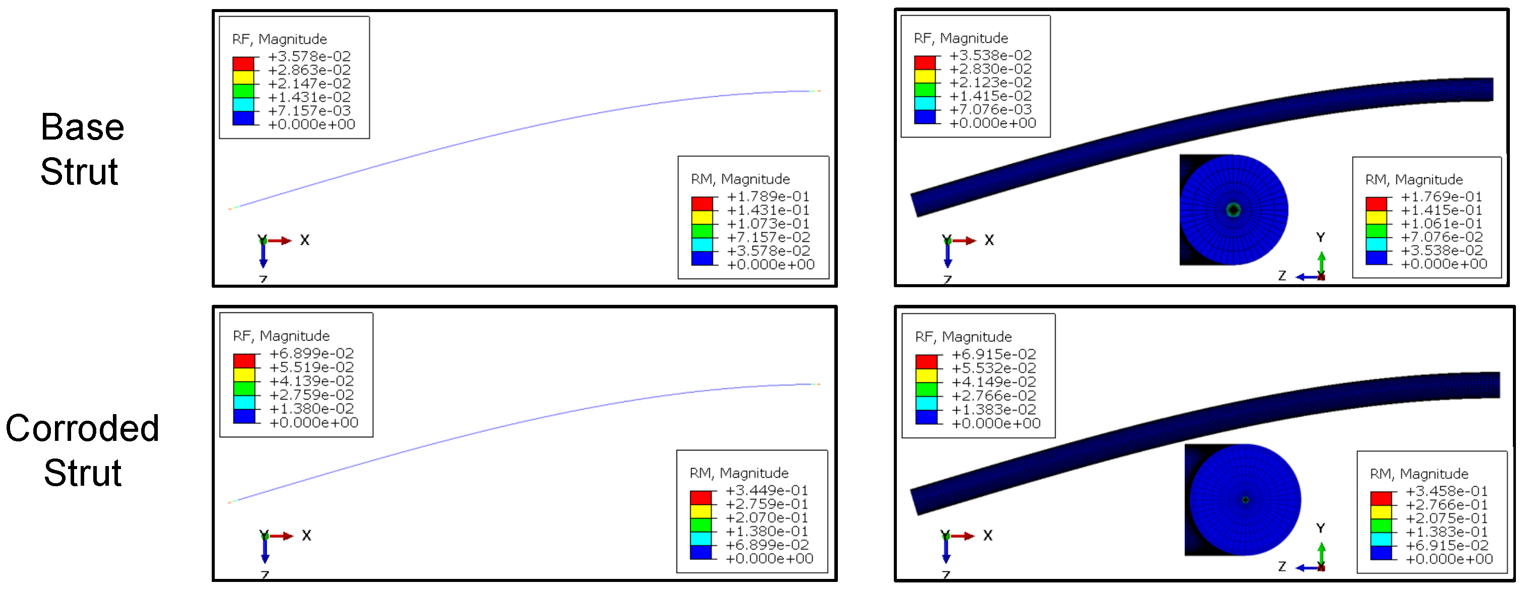
3.2.1. Single Strut Simulations
3.2.2. Whole Scaffold Modeling
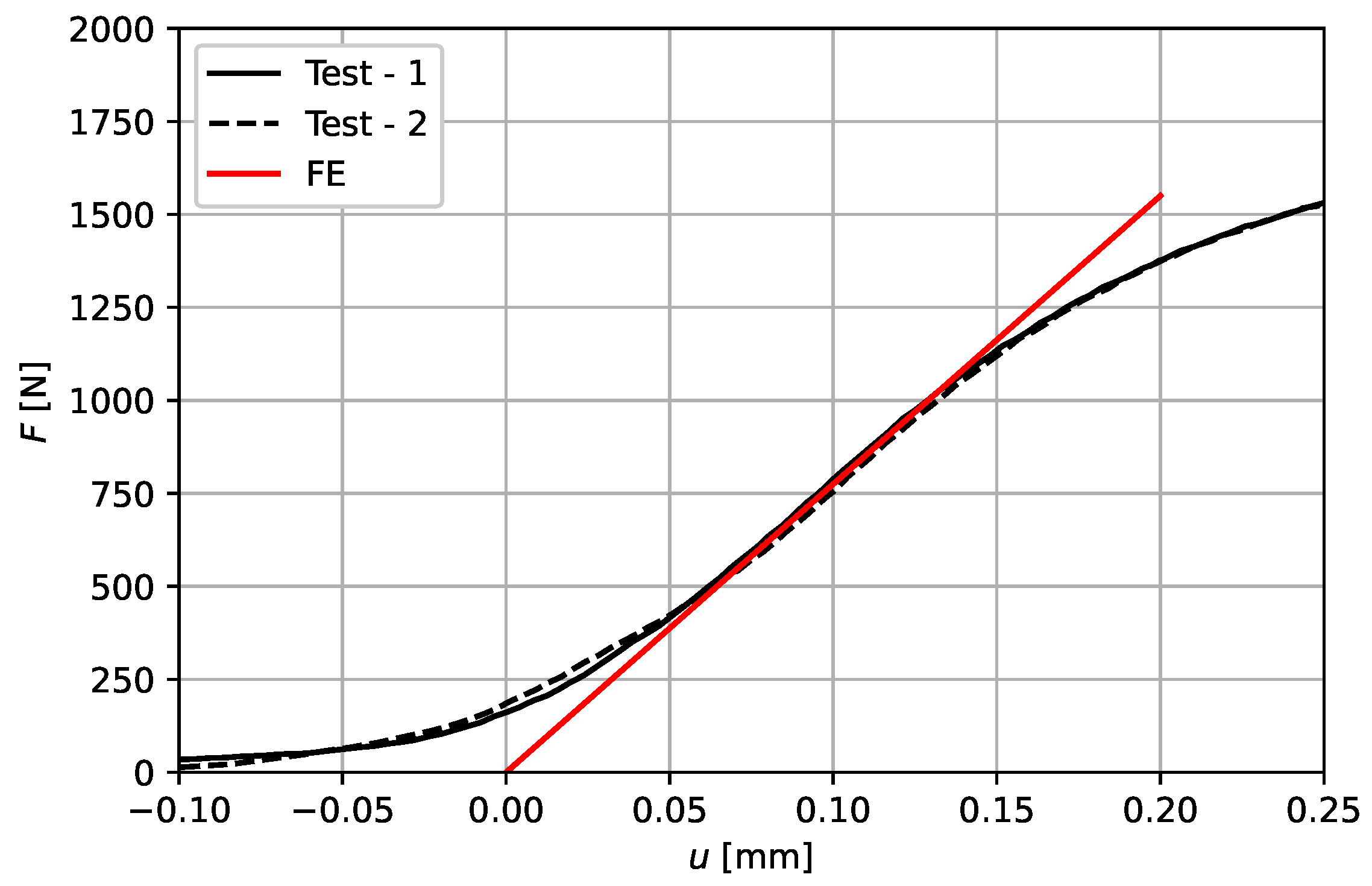
3.3. Confirmation by Physical Evaluation
4. Discussion
5. Conclusions
Author Contributions
Funding
Institutional Review Board Statement
Informed Consent Statement
Data Availability Statement
Acknowledgments
Conflicts of Interest
References
- Böstman, O.; Pihlajamäki, H. Clinical biocompatibility of biodegradable orthopaedic implants for internal fixation: A review. Biomaterials 2000, 21, 2615–2621. [Google Scholar] [CrossRef]
- Li, Y.; Zhou, J.; Pavanram, P.; Leeflang, M.A.; Fockaert, L.I.; Pouran, B.; Tümer, N.; Schröder, K.U.; Mol, J.M.C.; Weinans, H.; et al. Additively manufactured biodegradable porous magnesium. Acta Biomater. 2018, 67, 378–392. [Google Scholar] [CrossRef] [PubMed]
- Jahr, H.; Li, Y.; Zhou, J.; Zadpoor, A.A.; Schröder, K.U. Additively Manufactured Absorbable Porous Metal Implants—Processing, Alloying and Corrosion Behavior. Front. Mater. 2021, 8, 292. [Google Scholar] [CrossRef]
- Liu, X.; Ma, P.X. Polymeric scaffolds for bone tissue engineering. Ann. Biomed. Eng. 2004, 32, 477–486. [Google Scholar] [CrossRef] [PubMed]
- Seitz, H.; Rieder, W.; Irsen, S.; Leukers, B.; Tille, C. Three-dimensional printing of porous ceramic scaffolds for bone tissue engineering. J. Biomed. Mater. Res. Part B—Appl. Biomater. 2005, 74B, 782–788. [Google Scholar] [CrossRef]
- Chen, Q.; Thouas, G.A. Metallic implant biomaterials. Mater. Sci. Eng. R Rep. 2015, 87, 1–57. [Google Scholar] [CrossRef]
- Cutolo, A.; Engelen, B.; Desmet, W.; van Hooreweder, B. Mechanical properties of diamond lattice Ti–6Al–4V structures produced by laser powder bed fusion: On the effect of the load direction. J. Mech. Behav. Biomed. Mater. 2020, 104, 103656. [Google Scholar] [CrossRef]
- Gümrük, R.; Mines, R.; Karadeniz, S. Static mechanical behaviours of stainless steel micro-lattice structures under different loading conditions. Mater. Sci. Eng. A 2013, 586, 392–406. [Google Scholar] [CrossRef]
- Yan, Q.; Dong, H.; Su, J.; Han, J.; Song, B.; Wei, Q.; Shi, Y. A Review of 3D Printing Technology for Medical Applications. Engineering 2018, 4, 729–742. [Google Scholar] [CrossRef]
- Li, Y.; Jahr, H.; Zhou, J.; Zadpoor, A.A. Additively manufactured biodegradable porous metals. Acta Biomater. 2020, 115, 29–50. [Google Scholar] [CrossRef] [PubMed]
- Wang, J.L.; Xu, J.K.; Hopkins, C.; Chow, D.H.K.; Qin, L. Biodegradable Magnesium-Based Implants in Orthopedics-A General Review and Perspectives. Adv. Sci. 2020, 7, 1902443. [Google Scholar] [CrossRef]
- Wen, P.; Voshage, M.; Jauer, L.; Chen, Y.; Qin, Y.; Poprawe, R.; Schleifenbaum, J.H. Laser additive manufacturing of Zn metal parts for biodegradable applications: Processing, formation quality and mechanical properties. Mater. Des. 2018, 155, 36–45. [Google Scholar] [CrossRef]
- Qin, Y.; Wen, P.; Guo, H.; Xia, D.; Zheng, Y.; Jauer, L.; Poprawe, R.; Voshage, M.; Schleifenbaum, J.H. Additive manufacturing of biodegradable metals: Current research status and future perspectives. Acta Biomater. 2019, 98, 3–22. [Google Scholar] [CrossRef] [PubMed]
- Li, Y.; Jahr, H.; Lietaert, K.; Pavanram, P.; Yilmaz, A.; Fockaert, L.I.; Leeflang, M.A.; Pouran, B.; Gonzalez-Garcia, Y.; Weinans, H.; et al. Additively manufactured biodegradable porous iron. Acta Biomater. 2018, 77, 380–393. [Google Scholar] [CrossRef] [PubMed]
- Li, Y.; Jahr, H.; Pavanram, P.; Bobbert, F.S.L.; Paggi, U.; Zhang, X.Y.; Pouran, B.; Leeflang, M.A.; Weinans, H.; Zhou, J.; et al. Additively manufactured functionally graded biodegradable porous iron. Acta Biomater. 2019, 96, 646–661. [Google Scholar] [CrossRef] [PubMed]
- Song, B.; Dong, S.; Deng, S.; Liao, H.; Coddet, C. Microstructure and tensile properties of iron parts fabricated by selective laser melting. Opt. Laser Technol. 2014, 56, 451–460. [Google Scholar] [CrossRef]
- Song, B.; Dong, S.; Liu, Q.; Liao, H.; Coddet, C. Vacuum heat treatment of iron parts produced by selective laser melting: Microstructure, residual stress and tensile behavior. Mater. Des. 2014, 54, 727–733. [Google Scholar] [CrossRef]
- Montani, M.; Demir, A.; Mostaed, E.; Vedani, M.; Previtali, B. Processability of pure Zn and pure Fe by SLM for biodegradable metallic implant manufacturing. Rapid Prototyp. J. 2017, 23, 514–523. [Google Scholar] [CrossRef]
- Yang, Y.; Yuan, F.; Gao, C.; Feng, P.; Xue, L.; He, S.; Shuai, C. A combined strategy to enhance the properties of Zn by laser rapid solidification and laser alloying. J. Mech. Behav. Biomed. Mater. 2018, 82, 51–60. [Google Scholar] [CrossRef]
- Zhou, Y.; Wu, P.; Yang, Y.; Gao, D.; Feng, P.; Gao, C.; Wu, H.; Liu, Y.; Bian, H.; Shuai, C. The microstructure, mechanical properties and degradation behavior of laser-melted Mg Sn alloys. J. Alloys Compd. 2016, 687, 109–114. [Google Scholar] [CrossRef]
- Ng, C.C.; Savalani, M.M.; Lau, M.L.; Man, H.C. Fabrication of magnesium using selective laser melting technique. Rapid Prototyp. J. 2011, 17, 479–490. [Google Scholar] [CrossRef]
- Ng, C.C.; Savalani, M.M.; Lau, M.L.; Man, H.C. Microstructure and mechanical properties of selective laser melted magnesium. Appl. Surf. Sci. 2011, 257, 7447–7454. [Google Scholar] [CrossRef]
- Wei, K.; Zeng, X.; Wang, Z.; Deng, J.; Liu, M.; Huang, G.; Yuan, X. Selective laser melting of Mg-Zn binary alloys: Effects of Zn content on densification behavior, microstructure, and mechanical property. Mater. Sci. Eng. A 2019, 756, 226–236. [Google Scholar] [CrossRef]
- Kubásek, J.; Dvorský, D.; Čapek, J.; Pinc, J.; Vojtěch, D. Zn-Mg Biodegradable Composite: Novel Material with Tailored Mechanical and Corrosion Properties. Materials 2019, 12, 3930. [Google Scholar] [CrossRef] [PubMed] [Green Version]
- Frank, W.; Lucas, J.; Wolfgang, M.; Zienab, K.; Kristin, S.; Tanja, S. Open-porous biodegradable magnesium scaffolds produced by selective laser melting for individualized bone replacement. Front. Bioeng. Biotechnol. 2016, 4. [Google Scholar] [CrossRef]
- Kopp, A.; Derra, T.; Müther, M.; Jauer, L.; Schleifenbaum, J.H.; Voshage, M.; Jung, O.; Smeets, R.; Kröger, N. Influence of design and postprocessing parameters on the degradation behavior and mechanical properties of additively manufactured magnesium scaffolds. Acta Biomater. 2019, 98, 23–35. [Google Scholar] [CrossRef] [PubMed]
- Cockerill, I.; Su, Y.; Sinha, S.; Qin, Y.X.; Zheng, Y.; Young, M.L.; Zhu, D. Porous zinc scaffolds for bone tissue engineering applications: A novel additive manufacturing and casting approach. Mater. Sci. Eng. C Mater. Biol. Appl. 2020, 110, 110738. [Google Scholar] [CrossRef] [PubMed]
- Li, Y.; Pavanram, P.; Zhou, J.; Lietaert, K.; Taheri, P.; Li, W.; San, H.; Leeflang, M.A.; Mol, J.M.C.; Jahr, H.; et al. Additively manufactured biodegradable porous zinc. Acta Biomater. 2020, 101, 609–623. [Google Scholar] [CrossRef]
- Han, H.S.; Loffredo, S.; Jun, I.; Edwards, J.; Kim, Y.C.; Seok, H.K.; Witte, F.; Mantovani, D.; Glyn-Jones, S. Current status and outlook on the clinical translation of biodegradable metals. Mater. Today 2019, 23, 57–71. [Google Scholar] [CrossRef]
- Zheng, Y.F.; Gu, X.N.; Witte, F. Biodegradable metals. Mater. Sci. Eng. R Rep. 2014, 77, 1–34. [Google Scholar] [CrossRef]
- Li, P. Absorbable Zinc-based alloy for craniomaxillofacial osteosynthesis implants. In Faculty of Medicine; Eberhard Karls University Tübingen: Tübingen, Germany, 2020. [Google Scholar]
- Kannan, M.B.; Moore, C.; Saptarshi, S.; Somasundaram, S.; Rahuma, M.; Lopata, A.L. Biocompatibility and biodegradation studies of a commercial zinc alloy for temporary mini-implant applications. Sci. Rep. 2017, 7, 15605. [Google Scholar] [CrossRef] [PubMed] [Green Version]
- Meiners, W. Direktes Selektives Laser-Sintern Einkomponentiger Metallischer Werkstoffe. Ph.D. Thesis, RWTH Aachen University, Aachen, Germany, 1999. [Google Scholar]
- Ulutan, S.; Gilbert, M. Mechanical properties of HDPE/magnesium hydroxide composites. J. Mater. Sci. 2000, 35, 2115–2120. [Google Scholar] [CrossRef]
- Ulian, G.; Valdrè, G. Anisotropy and directional elastic behavior data obtained from the second-order elastic constants of portlandite Ca(OH)2 and brucite Mg(OH)2. Data Brief 2018, 21, 1375–1380. [Google Scholar] [CrossRef] [PubMed]
- Yao, C.; Wu, Z.; Zou, F.; Sun, W. Thermodynamic and Elastic Properties of Magnesite at Mantle Conditions: First-Principles Calculations. Geochem. Geophys. Geosyst. 2018, 19, 2719–2731. [Google Scholar] [CrossRef]


| i | [mm] | [mm] | [mm] | [] | [mm] | [mm] | [mm] | [] |
|---|---|---|---|---|---|---|---|---|
| 1 | 1.4 | 1.376 | 0.515 | 62.8 | 2.3 | 2.261 | 0.845 | 49.8 |
| 2 | 2.3 | 2.261 | 0.845 | 49.8 | 3.2 | 3.146 | 1.176 | 40.4 |
| 3 | 3.2 | 3.146 | 1.176 | 40.4 | 4.1 | 4.030 | 1.507 | 33.6 |
| 4 | 4.1 | 4.030 | 1.507 | 33.6 | 5.0 | 4.917 | 1.838 | 28.6 |
| [GPa] | [µm] | [mm] | ||||
|---|---|---|---|---|---|---|
| 0.05 | 0.1 | 0.15 | 0.2 | 0.25 | ||
| 19 | 5 | 22% | 11% | 8% | 6% | 4% |
| 10 | 46% | 23% | 15% | 11% | 9% | |
| 20 | 102% | 49% | 35% | 23% | 18% | |
| 38 | 5 | 43% | 22% | 14% | 11% | 8% |
| 10 | 91% | 44% | 29% | 22% | 17% | |
| 20 | 201% | 95% | 61% | 45% | 35% | |
| 57 | 5 | 64% | 32% | 21% | 16% | 13% |
| 10 | 136% | 66% | 43% | 32% | 25% | |
| 20 | 300% | 140% | 90% | 66% | 52% | |
| 76 | 5 | 85% | 42% | 28% | 21% | 17% |
| 10 | 180% | 87% | 57% | 42% | 34% | |
| 20 | 353% | 164% | 106% | 78% | 61% | |
Publisher’s Note: MDPI stays neutral with regard to jurisdictional claims in published maps and institutional affiliations. |
© 2021 by the authors. Licensee MDPI, Basel, Switzerland. This article is an open access article distributed under the terms and conditions of the Creative Commons Attribution (CC BY) license (https://creativecommons.org/licenses/by/4.0/).
Share and Cite
Bühring, J.; Voshage, M.; Schleifenbaum, J.H.; Jahr, H.; Schröder, K.-U. Influence of Degradation Product Thickness on the Elastic Stiffness of Porous Absorbable Scaffolds Made from an Bioabsorbable Zn–Mg Alloy. Materials 2021, 14, 6027. https://doi.org/10.3390/ma14206027
Bühring J, Voshage M, Schleifenbaum JH, Jahr H, Schröder K-U. Influence of Degradation Product Thickness on the Elastic Stiffness of Porous Absorbable Scaffolds Made from an Bioabsorbable Zn–Mg Alloy. Materials. 2021; 14(20):6027. https://doi.org/10.3390/ma14206027
Chicago/Turabian StyleBühring, Jannik, Maximilian Voshage, Johannes Henrich Schleifenbaum, Holger Jahr, and Kai-Uwe Schröder. 2021. "Influence of Degradation Product Thickness on the Elastic Stiffness of Porous Absorbable Scaffolds Made from an Bioabsorbable Zn–Mg Alloy" Materials 14, no. 20: 6027. https://doi.org/10.3390/ma14206027