Effect of Phase Transformation on Stress Corrosion Behavior of Additively Manufactured Austenitic Stainless Steel Produced by Directed Energy Deposition


Abstract
:1. Introduction
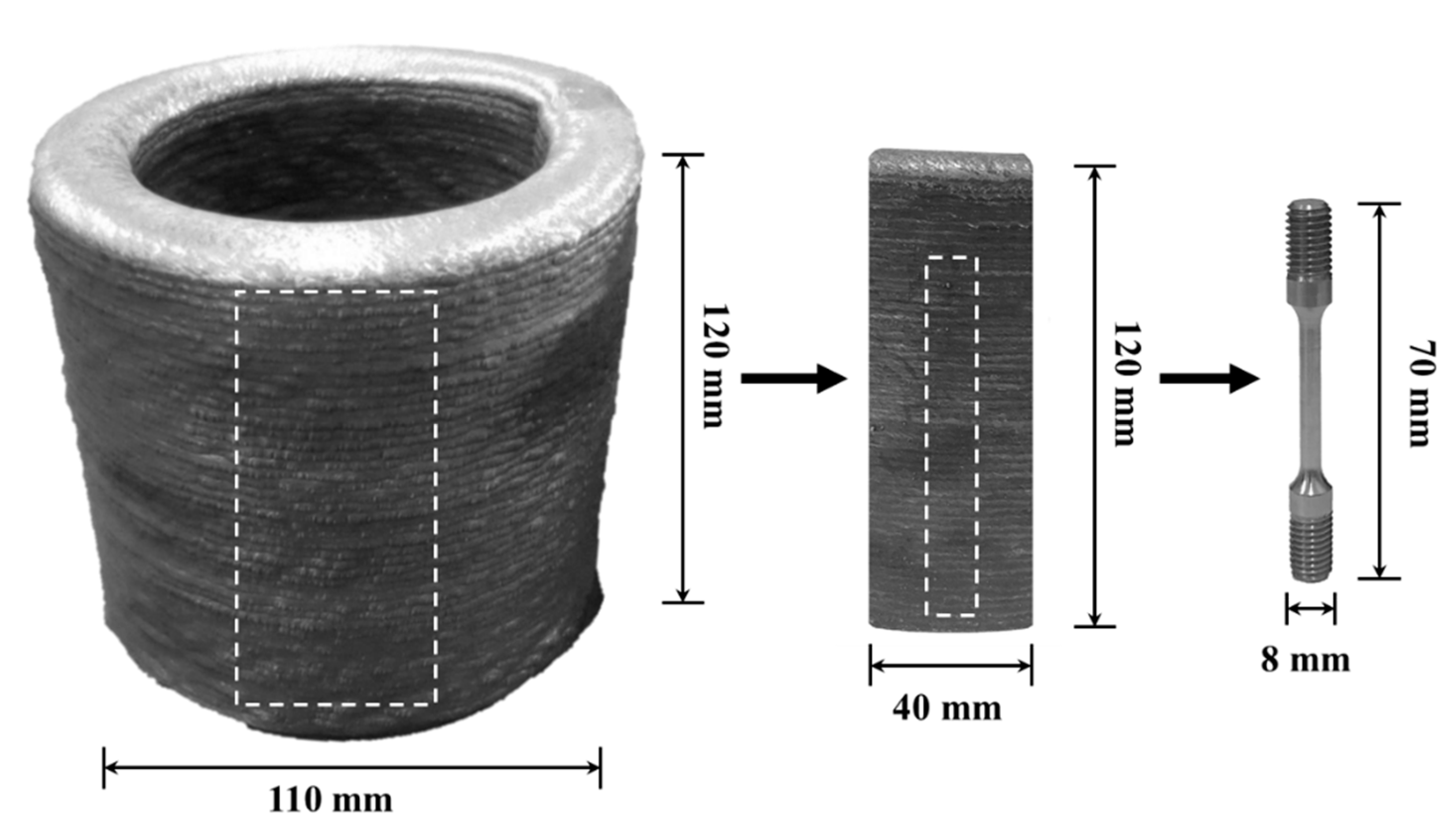
2. Materials and Methods
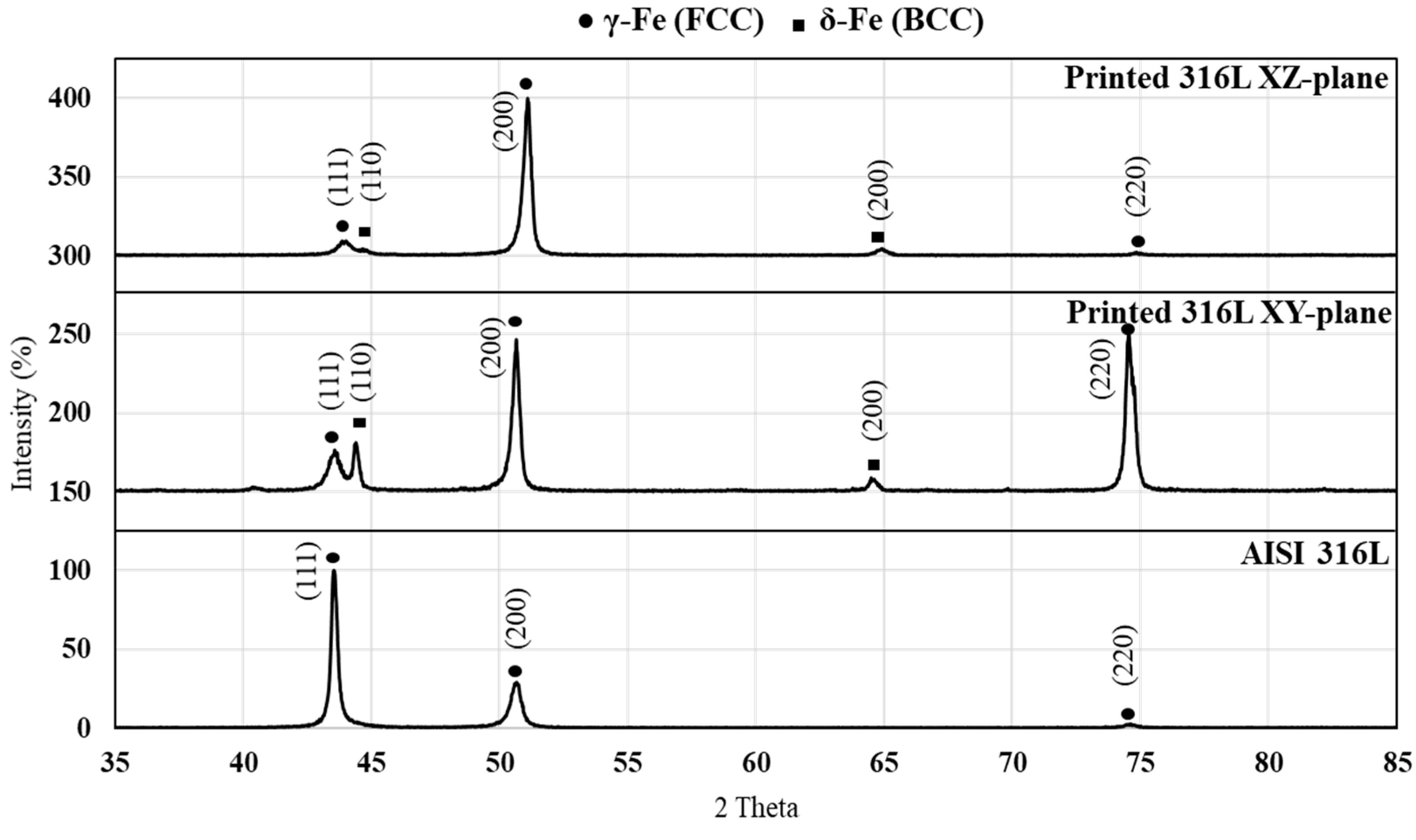
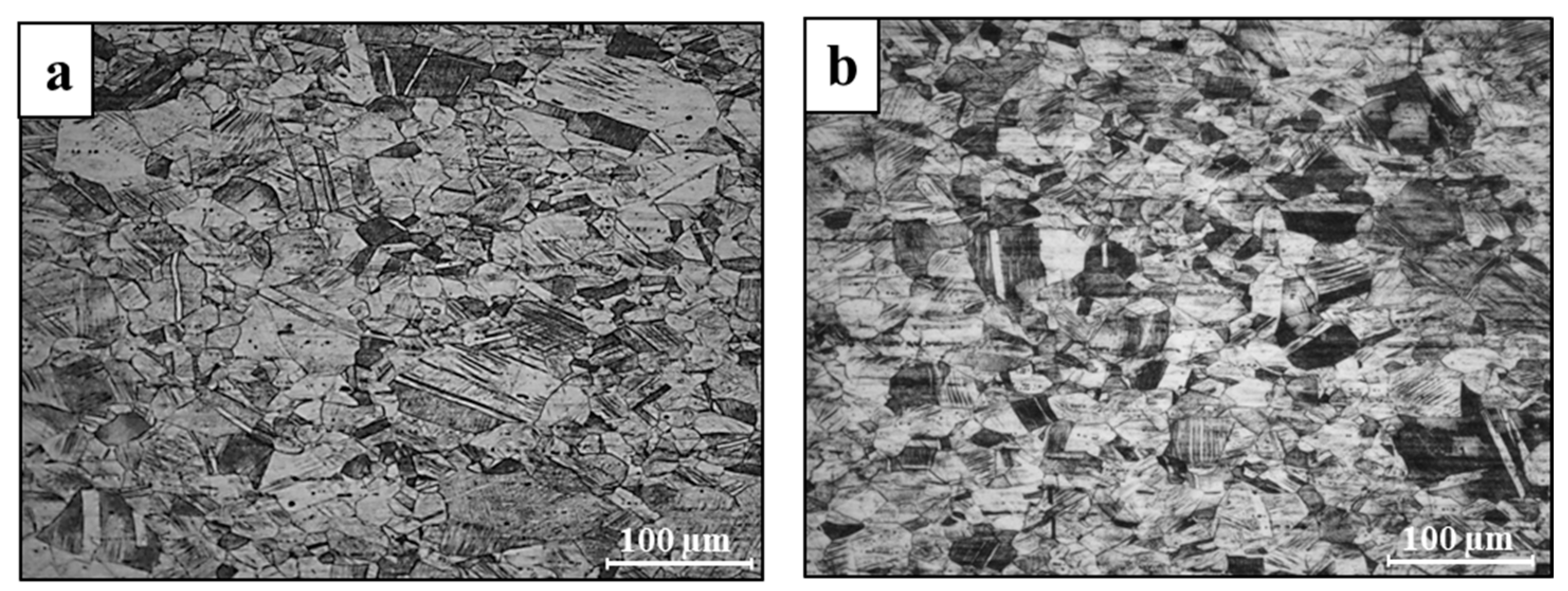
3. Results
4. Discussion
5. Conclusions
Author Contributions
Funding
Institutional Review Board Statement
Informed Consent Statement
Data Availability Statement
Acknowledgments
Conflicts of Interest
References
- Leon, A.; Levy, G.K.; Ron, T.; Shirizly, A.; Aghion, E. The effect of strain rate on stress corrosion performance of Ti6Al4V alloy produced by additive manufacturing process. J. Mater. Res. Technol. 2020. [Google Scholar] [CrossRef]
- Rodrigues, T.A.; Duarte, V.; Avila, J.A.; Santos, T.G.; Miranda, R.; Oliveira, J. Wire and arc additive manufacturing of HSLA steel: Effect of thermal cycles on microstructure and mechanical properties. Addit. Manuf. 2019, 27, 440–450. [Google Scholar] [CrossRef]
- Ding, D.; Pan, Z.; Cuiuri, D.; Li, H. Wire-feed additive manufacturing of metal components: Technologies, developments and future interests. Int. J. Adv. Manuf. Technol. 2015, 81, 465–481. [Google Scholar] [CrossRef]
- Leon, A.; Shirizly, A.; Aghion, E. Corrosion Behavior of AlSi10Mg Alloy Produced by Additive Manufacturing (AM) vs. Its Counterpart Gravity Cast Alloy. Metals 2016, 6, 148. [Google Scholar] [CrossRef]
- Herzog, D.; Seyda, V.; Wycisk, E.; Emmelmann, C. Additive manufacturing of metals. Acta Mater. 2016, 117, 371–392. [Google Scholar] [CrossRef]
- Haghdadi, N.; Laleh, M.; Moyle, M.; Primig, S. Additive manufacturing of steels: A review of achievements and challenges. J. Mater. Sci. 2020, 56, 64–107. [Google Scholar] [CrossRef]
- Leon, A.; Levy, G.K.; Ron, T.; Shirizly, A.; Aghion, E. The effect of hot isostatic pressure on the corrosion performance of Ti6Al4V produced by an electron-beam melting additive manufacturing process. Addit. Manuf. 2020, 33, 101039. [Google Scholar] [CrossRef]
- Zakay, A.; Aghion, E. Effect of Post-heat Treatment on the Corrosion Behavior of AlSi10Mg Alloy Produced by Additive Manufacturing. JOM 2019, 71, 1150–1157. [Google Scholar] [CrossRef]
- Rodrigues, T.A.; Duarte, V.; Miranda, R.M.; Santos, T.G.; Oliveira, J.P. Current Status and Perspectives on Wire and Arc Additive Manufacturing (WAAM). Materials 2019, 12, 1121. [Google Scholar] [CrossRef] [Green Version]
- Ding, D.; Pan, Z.; Cuiuri, D.; Li, H. A multi-bead overlapping model for robotic wire and arc additive manufacturing (WAAM). Robot. Comput. Manuf. 2015, 31, 101–110. [Google Scholar] [CrossRef] [Green Version]
- Gisario, A.; Kazarian, M.; Martina, F.; Mehrpouya, M. Metal additive manufacturing in the commercial aviation industry: A review. J. Manuf. Syst. 2019, 53, 124–149. [Google Scholar] [CrossRef]
- Donoghue, J.M.; Antonysamy, A.A.; Martina, F.; Colegrove, P.; Williams, S.W.; Prangnell, P. The effectiveness of combining rolling deformation with Wire–Arc Additive Manufacture on β-grain refinement and texture modification in Ti-6Al-4V. Mater. Charact. 2016, 114, 103–114. [Google Scholar] [CrossRef]
- Busachi, A.; Erkoyuncu, J.; Colegrove, P.; Martina, F.; Watts, C.; Drake, R. A review of Additive Manufacturing technology and Cost Estimation techniques for the defence sector. CIRP J. Manuf. Sci. Technol. 2017, 19, 117–128. [Google Scholar] [CrossRef] [Green Version]
- Bekker, A.C.M.; Verlinden, J.C.; Galimberti, G. Challenges in assessing the sustainability of wire+ arc additive manufacturing for large structures. In Proceedings of the Solid Freeform Fabrication Symposium, Austin, TX, USA, 8–10 August 2016; pp. 406–418. [Google Scholar]
- Cunningham, C.R.; Wikshåland, S.; Xu, F.; Kemakolam, N.; Shokrani, A.; Dhokia, V.; Newman, S. Cost Modelling and Sensitivity Analysis of Wire and Arc Additive Manufacturing. Procedia Manuf. 2017, 11, 650–657. [Google Scholar] [CrossRef]
- Ron, T.; Levy, G.K.; Dolev, O.; Leon, A.; Shirizly, A.; Aghion, E. Environmental Behavior of Low Carbon Steel Produced by a Wire Arc Additive Manufacturing Process. Metals 2019, 9, 888. [Google Scholar] [CrossRef] [Green Version]
- Bandari, Y.K.; Williams, S.W.; Ding, J.; Martina, F. Additive manufacture of large structures: Robotic or CNC systems. In Proceedings of the 26th international solid freeform fabrication symposium, Austin, TX, USA, 10–12 August 2015; pp. 12–14. [Google Scholar]
- Williams, S.W.; Martina, F.; Addison, A.C.; Ding, J.; Pardal, G.; Colegrove, P.A. Wire + Arc Additive Manufacturing. Mater. Sci. Technol. 2016, 32, 641–647. [Google Scholar] [CrossRef] [Green Version]
- Ron, T.; Levy, G.K.; Dolev, O.; Leon, A.; Shirizly, A.; Aghion, E. The Effect of Microstructural Imperfections on Corrosion Fatigue of Additively Manufactured ER70S-6 Alloy Produced by Wire Arc Deposition. Metals 2020, 10, 98. [Google Scholar] [CrossRef] [Green Version]
- Shirizly, A.; Dolev, O. From Wire to Seamless Flow-Formed Tube: Leveraging the Combination of Wire Arc Additive Manufacturing and Metal Forming. JOM 2018, 71, 709–717. [Google Scholar] [CrossRef] [Green Version]
- Derekar, K.S. A review of wire arc additive manufacturing and advances in wire arc additive manufacturing of aluminium. Mater. Sci. Technol. 2018, 34, 895–916. [Google Scholar] [CrossRef]
- Wu, B.; Pan, Z.; Ding, D.; Cuiuri, D.; Li, H.; Xu, J.; Norrish, J. A review of the wire arc additive manufacturing of metals: Properties, defects and quality improvement. J. Manuf. Process. 2018, 35, 127–139. [Google Scholar] [CrossRef]
- Pan, Z.; Ding, D.; Wu, B.; Cuiuri, D.; Li, H.; Norrish, J. Arc Welding Processes for Additive Manufacturing: A Review; Springer Science and Business Media LLC: Berlin, Germany, 2017; pp. 3–24. [Google Scholar]
- Wang, L.; Xue, J.; Wang, Q. Correlation between arc mode, microstructure, and mechanical properties during wire arc additive manufacturing of 316L stainless steel. Mater. Sci. Eng. A 2019, 751, 183–190. [Google Scholar] [CrossRef]
- Chen, X.; Li, J.; Cheng, X.; He, B.; Wang, H.; Huang, Z. Microstructure and mechanical properties of the austenitic stainless steel 316L fabricated by gas metal arc additive manufacturing. Mater. Sci. Eng. A 2017, 703, 567–577. [Google Scholar] [CrossRef]
- Kaya, A.; Uzan, P.; Eliezer, D.; Aghion, E. Electron microscopical investigation of as cast AZ91D alloy. Mater. Sci. Technol. 2000, 16, 1001–1006. [Google Scholar] [CrossRef]
- Aghion, E.; Gueta, Y.; Moscovitch, N.; Bronfin, B. Effect of yttrium additions on the properties of grain-refined Mg–3%Nd alloy. J. Mater. Sci. 2008, 43, 4870–4875. [Google Scholar] [CrossRef]
- Available online: https://www.astm.org/Standards/G129 (accessed on 21 December 2020).
- Arnon, A.; Aghion, E. Stress Corrosion Cracking of Nano/Sub-micron E906 Magnesium Alloy. Adv. Eng. Mater. 2008, 10, 742–745. [Google Scholar] [CrossRef]
- Hakimi, O.; Aghion, E.; Goldman, J. Improved stress corrosion cracking resistance of a novel biodegradable EW62 magnesium alloy by rapid solidification, in simulated electrolytes. Mater. Sci. Eng. C 2015, 51, 226–232. [Google Scholar] [CrossRef]
- Guo, P.; Zou, B.; Huang, C.; Gao, H. Study on microstructure, mechanical properties and machinability of efficiently additive manufactured AISI 316L stainless steel by high-power direct laser deposition. J. Mater. Process. Technol. 2017, 240, 12–22. [Google Scholar] [CrossRef]
- Chen, X.; Li, J.; Cheng, X.; Wang, H.; Huang, Z. Effect of heat treatment on microstructure, mechanical and corrosion properties of austenitic stainless steel 316L using arc additive manufacturing. Mater. Sci. Eng. A 2018, 715, 307–314. [Google Scholar] [CrossRef]
- Xiong, J.; Tan, M.Y.; Forsyth, M. The corrosion behaviors of stainless steel weldments in sodium chloride solution observed using a novel electrochemical measurement approach. Desalination 2013, 327, 39–45. [Google Scholar] [CrossRef]
- Koseki, T.; Flemings, M.C. Solidification of undercooled Fe-Cr-Ni alloys: Part I. Thermal behavior. Met. Mater. Trans. A 1995, 26, 2991–2999. [Google Scholar] [CrossRef]
- Itzhak, D.; Aghion, E. Corrosion behaviour of hot-pressed austenitic stainless steel in H2SO4 solutions at room temperature. Corros. Sci. 1983, 23, 1085–1094. [Google Scholar] [CrossRef]
- Itzhak, D.; Aghion, E. An anodic behaviour study of an analogical sintered system of austenitic stainless steel in H2SO4 solution. Corros. Sci. 1984, 24, 145–149. [Google Scholar] [CrossRef]
- Garcia-Cabezon, C.; Martín, F.; Blanco, Y.; De Tiedra, P.; Aparicio, M. Corrosion behaviour of duplex stainless steels sintered in nitrogen. Corros. Sci. 2009, 51, 76–86. [Google Scholar] [CrossRef]
- Al Saadi, S.; Yi, Y.; Cho, P.; Jang, C.; Beeley, P. Passivity breakdown of 316L stainless steel during potentiodynamic polarization in NaCl solution. Corros. Sci. 2016, 111, 720–727. [Google Scholar] [CrossRef]
- Leon, A.; Aghion, E. Effect of surface roughness on corrosion fatigue performance of AlSi10Mg alloy produced by Selective Laser Melting (SLM). Mater. Charact. 2017, 131, 188–194. [Google Scholar] [CrossRef]
- Kafri, A.; Ovadia, S.; Yosafovich-Doitch, G.; Aghion, E. The Effects of 4%Fe on the Performance of Pure Zinc as Biodegradable Implant Material. Ann. Biomed. Eng. 2019, 47, 1400–1408. [Google Scholar] [CrossRef]
- Kubík, P.; Šebek, F.; Petruška, J.; Hůlka, J.; Park, N.; Huh, H. Comparative investigation of ductile fracture with 316L austenitic stainless steel in small punch tests: Experiments and simulations. Theor. Appl. Fract. Mech. 2018, 98, 186–198. [Google Scholar] [CrossRef]


| Material | C | Mn | Si | S | P | Cr | Ni | Cu | Mo | Co | N | Fe |
|---|---|---|---|---|---|---|---|---|---|---|---|---|
| Welding Wire | 0.013 | 1.97 | 0.51 | 0.0010 | 0.018 | 19.22 | 11.50 | 0.15 | 2.42 | 0.07 | 0.092 | Bal. |
| Printed 316L | 0.024 | 1.85 | 0.44 | 0.0007 | 0.020 | 19.21 | 11.62 | 0.09 | 2.48 | 0.26 | 0.052 | Bal. |
| AISI 316L | 0.021 | 1.59 | 0.40 | 0.02 | 0.037 | 16.58 | 10.07 | 0.44 | 2.04 | 0.19 | 0.078 | Bal. |
| Test Point | C | Mn | Si | Cr | Ni | Mo | Fe |
|---|---|---|---|---|---|---|---|
| Point 1 | 0.39 | 2.3 | 0.41 | 17.34 | 12.08 | 2.02 | Bal. |
| Point 2 | 0.25 | 2.12 | 0.39 | 24.86 | 5.43 | 4.17 | Bal. |
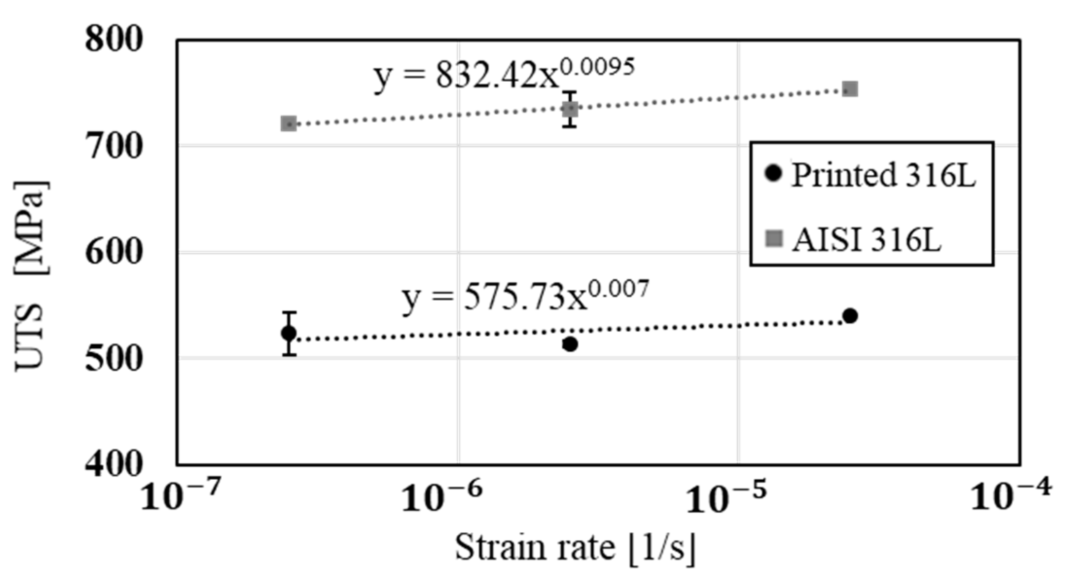
| Material | UTS (MPa) | YP (MPa) | Elongation (%) | Hardness (HV) | Density (gr/cm3) |
|---|---|---|---|---|---|
| Printed 316L | 552 ± 11 | 364 ± 17 | 42 ± 1 | 196 ± 5 | 7.6 ± 0.3 |
| AISI 316L | 752 ± 3 | 695 ± 3 | 37 ± 1 | 275 ± 9 | 7.8 ± 0.2 |
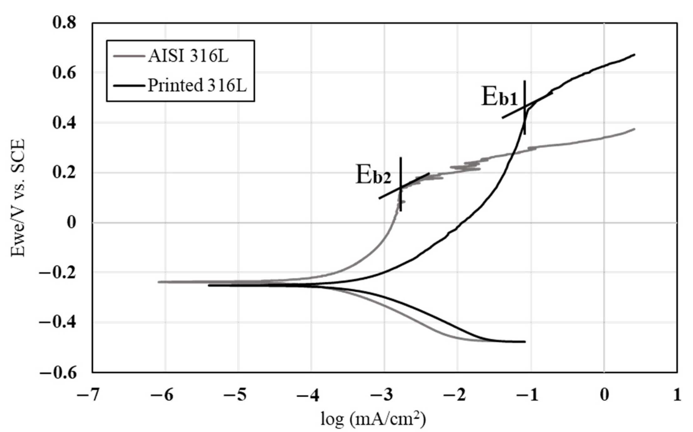
| Material | Ecorr (v) | Icorr (μA/cm2) | Corrosion Rate (mmpy) | Ebreak (v) |
|---|---|---|---|---|
| Printed 316L | −0.25 ± 0.02 | 0.48 ± 0.12 | 0.005 ± 0.001 | 0.47 ± 0.03 |
| AISI 316L | −0.21 ± 0.02 | 0.09 ± 0.004 | 0.001 ± 0.0003 | 0.18 ± 0.004 |
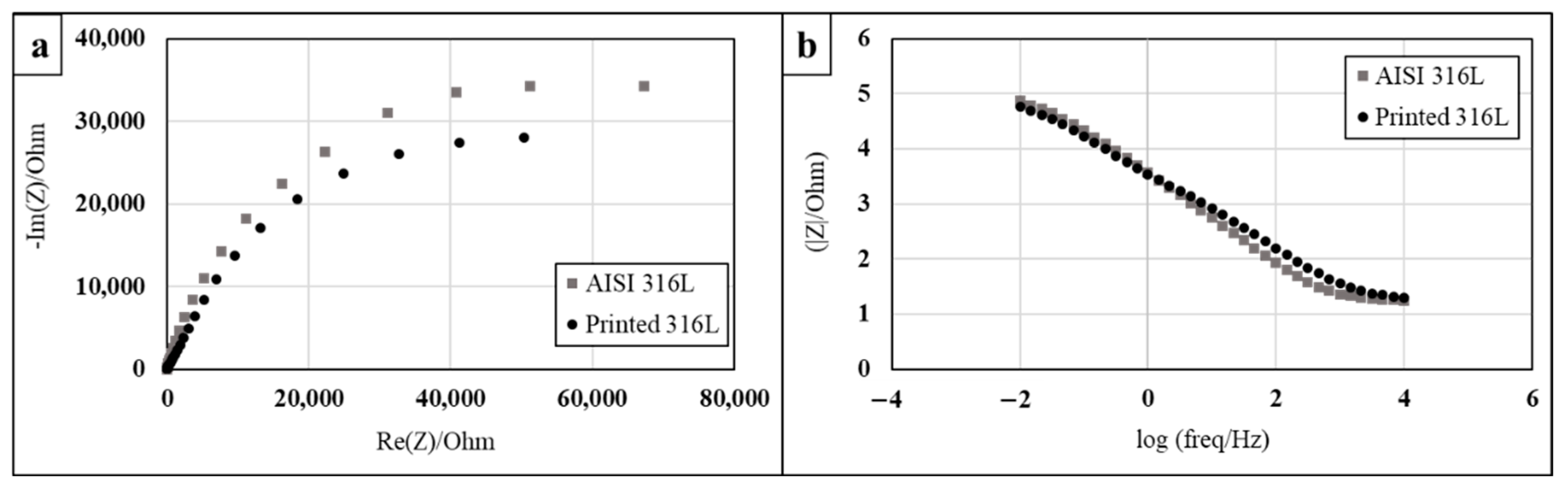
| Material | R1 (Ohm) | Q1 (F·sa−1) | a | R2 (Ohm) |
|---|---|---|---|---|
| Printed 316L | 15.6 | 7.31 × 10⁻⁵ | 0.705 | 92,178 |
| AISI 316L | 16.98 | 6.07 × 10⁻⁵ | 0.825 | 83,863 |
Publisher’s Note: MDPI stays neutral with regard to jurisdictional claims in published maps and institutional affiliations. |
© 2020 by the authors. Licensee MDPI, Basel, Switzerland. This article is an open access article distributed under the terms and conditions of the Creative Commons Attribution (CC BY) license (http://creativecommons.org/licenses/by/4.0/).
Share and Cite
Ron, T.; Dolev, O.; Leon, A.; Shirizly, A.; Aghion, E. Effect of Phase Transformation on Stress Corrosion Behavior of Additively Manufactured Austenitic Stainless Steel Produced by Directed Energy Deposition. Materials 2021, 14, 55. https://doi.org/10.3390/ma14010055
Ron T, Dolev O, Leon A, Shirizly A, Aghion E. Effect of Phase Transformation on Stress Corrosion Behavior of Additively Manufactured Austenitic Stainless Steel Produced by Directed Energy Deposition. Materials. 2021; 14(1):55. https://doi.org/10.3390/ma14010055
Chicago/Turabian StyleRon, Tomer, Ohad Dolev, Avi Leon, Amnon Shirizly, and Eli Aghion. 2021. "Effect of Phase Transformation on Stress Corrosion Behavior of Additively Manufactured Austenitic Stainless Steel Produced by Directed Energy Deposition" Materials 14, no. 1: 55. https://doi.org/10.3390/ma14010055