Article

An MV-Connected Ultra-Fast Charging Station Based on MMC and Dual Active Bridge with Multiple dc Buses

Department of Electronics, Information and Bioengineering, Politecnico di Milano, 20133 Milan, Italy
*
Author to whom correspondence should be addressed.
Energies 2023, 16(9), 3960; https://doi.org/10.3390/en16093960
Submission received: 7 February 2023 / Revised: 28 April 2023 / Accepted: 3 May 2023 / Published: 8 May 2023

Abstract

:
The diffusion of electric vehicles will be strongly related to the capacity to charge them in short times. To do so, the necessity of widespread fast charging stations arises. However, their intermittent demand represents a challenging load for grid operators. In order to relieve their impact on the electrical grid operation, integrating storage systems in the charging stations represents a potential solution, although it complicates the overall system management. Moreover, standard converter architectures for the MV grid interface require the installation of bulky transformers and filters. In order to cope with the mentioned problems, this paper proposes an ultra-fast charging station topology based on a modular multilevel converter (MMC) structure and dual-active bridge (DAB) converters. Thanks to the multilevel converter properties, the proposed charging station can be directly interfaced with the MV grid without requiring transformers or filters. Additionally, exploiting the degree of freedom in the converter control system, such as circulating components, offers uneven power distribution among the converter submodules that can be managed. Along with the MMC control strategy, the article addresses a straightforward methodology to select the main parameters of the DAB converter as a function of the involved grid power and circulating power contributions, with the primary goal of obtaining a trade-off between internal balancing performances and a broad soft-switching region without incurring in converter oversizing. The effectiveness of the proposed charging station is finally discussed through numerical simulations, where its behavior during a power demand cycle is analyzed.

1. Introduction

In recent years, the necessity to reduce carbon emissions has pushed institutions to promote and incentivize the adoption of low-emission vehicles and to move energy production from fossil fuels to renewable energy sources (RESs). Among low-emission vehicles, battery electric vehicles (BEVs) are gaining popularity and are supposed to grow in the following years. The will to boost their diffusion necessitates providing users with solid and widespread charging infrastructures. Moreover, in order to make BEVs competitive with internal combustion engines, it is essential to reduce the charging time by developing ultra-fast charging (UFC) stations [1]. However, a widespread UFC network represents a challenge for grid stability due to its intermittent high-power demand [2]. To decouple generation and demand, it is possible to exploit energy storage systems; in particular, the falling cost of batteries in recent years made using battery energy storage systems (BESSs) against other technologies more convenient [3]. Integrating BESSs within charging stations has been the subject of studies for many years, as proposed in [4,5]. Here, batteries can be used to provide peak shaving of the power demand in order to relieve the stress on the grid. Nevertheless, current UFC station topologies present different technological weaknesses leading to high costs and slowing down their diffusion. Some issues are mainly related to using two- or three-level inverter topologies since bulky medium-voltage/low-voltage (MV/LV) transformers and output filters are required for MV grid connection and power quality constraints. Moreover, problems arise whether BESSs with different voltage levels or based on different technologies have to be installed within the same station since further dc-dc converters are required to interface them. In order to cope with previous issues, solutions based on modular multilevel converters (MMCs), including cascaded H-bridge (CHB) converters and MMC in a double-star configuration, have been proposed in the technical literature to integrate storages for grid [6,7,8] or EV charging station applications [9,10,11,12]. The advantages of adopting these topologies are mainly the total harmonic distortion (THD) reduction at the point of common coupling (PCC) and the possibility of reaching a direct MV connection without needing a transformer. Furthermore, modular configurations allow for the integration of the storage system directly in the converter submodules (SMs) and to manage them directly through the converter control.
Focusing on EV charging station applications, Vasiladiotis et al. proposed different topologies and control of charging stations based on a CHB converter with a battery storage system split among the converter modules [9,10,11]. In these architectures, the SM configuration was based on the cascade connection of the main CHB H-bridge and a bi-directional buck converter to control the battery. The battery was then interfaced to the charging station dc bus by means of a dual active half-bridge converter with a unitary winding ratio. However, these topologies may suffer from battery insulation problems since they are placed in the converter SMs without galvanic insulation from the MV side. Moreover, the presence of two dc-dc converters, in addition to the H-module of the CHB, complicates the control and affects the overall efficiency. Investigations on using MMCs in a double-star configuration with the direct integration of batteries and charging spots within the SMs were investigated in [12]. However, the proposed charging station resulted in being unfeasible for direct MV connection. Indeed, even if the charging spots and the BESS can be split at the submodule level, the converter SMs may be interested, among them, in different charging powers, thus affecting the sizing of the installed BESS. In this regard, the authors demonstrate, by analyzing the internal converter power flow, that to avoid BESS oversizing, the rated voltage of the single SM must be higher than the voltage of the grid to which the charging station is connected. Thus, the charging station modularity is limited since only a few SMs are needed to synthesize the required voltages, and it can be connected to the MV grid merely through a transformer.
Therefore, charging station architectures able to handle various voltage and power levels while maintaining proper insulation with respect to the MV grid should be developed. In this regard, power electronic interfaces based on solid-state transformers are possible solutions. Examining the architectures proposed in the technical literature [13,14,15,16], they are typically based on a three-phase CHB converter used to interface the MV grid to LV dc systems. Indeed, each converter SM comprises an additional dc/dc stage based on a dual active bridge (DAB) converter to create an LV dc connection insulated from the grid. However, one of the major limitations of the proposed topologies is the existence of only one LV dc bus. Thus, integrating batteries with different technologies and reaching various voltage levels are not possible. To overcome this issue, in [17], the authors proposed a solution in which each phase of the CHB converter is used to create a dc port, reaching three different dc levels, integrating charging ports, storage systems, and photovoltaic (PV) panels. Nevertheless, there are no considerations regarding the sizing of the installed BESS and PV system. Moreover, since the CHB converter cannot form a common dc bus, the PV panels had to be integrated at different voltage levels, increasing the system complexity and component sizing.
In this scenario, this paper proposes a new topology for an insulated ultra-fast charging station topology based on an MMC in a double-star configuration directly connected to the MV grid. In this case, with respect to the CHB converter, the double-star MMC features an accessible dc side that can eventually be exploited to integrate other sources, including photovoltaic systems [18,19]. Each converter SM features a capacitor interfaced to a common dc bus through a dual active full-bridge (DAFB) converter, stepping down the voltage and controlling the power flow between the ac and dc sides. For each converter phase, the output terminals of the DAFB converters are connected in parallel, creating a dc port for a BESS. In this way, three different dc buses are provided, also enabling the capability of integrating batteries with different voltage levels and technologies. Moreover, the internal energy of the MMC can be handled by exploiting the generation of the circulating currents [20]. Considering the proposed charging station architecture, the three different dc buses and, thus, the three converter phases should satisfy different charging power levels due to the various vehicles charging simultaneously. In this situation, by exploiting the injection of only the dc circulating currents, power exchange among the converter phases can be established, achieving BESS SOC equalization. Therefore, with the proposed configuration, the power absorbed by the station is managed through the control of the MMC, while the power flow between the ac side and the dc buses can be managed by acting on the control of the DAFB converters. Additionally, the topology ensures the galvanic insulation of batteries with respect to the MV grid. In the following, the UFC station topology and control are described, starting from the grid-side control and moving to the DAFB converter operation. Furthermore, guidelines for the size of the BESS are also provided. Finally, a case study is defined, and the performances of the proposed UFC station are validated by means of numerical simulations in the MATLAB Simulink® environment.

2. Topology and Control of the Proposed Ultra-Fast Charging Station

The following section briefly outlines the proposed charging station topology. First, a general description is provided, highlighting the main stages composing the converter. Then, control and consideration of the operation of the MMC and DAFB converters are discussed.

2.1. Overview of the Proposed Charging Station Structure

The proposed UFC station topology is shown in Figure 1. As previously introduced, the grid interface consists of an MMC in a double-star chopper-cell configuration. Each converter SM is composed of a cascade of two main stages: the MMC half-bridge (HB) and the DAFB converter; the SM structure is reported in Figure 2. The purpose of the first SM stage, i.e., the MMC HB, is to synthesize the grid voltage, while the DAFB stages provide power exchange between the ac side and the charging station dc bus, and it is controlled to keep the SM capacitor voltage, vsm, at its rated value Vsm. The DAFB LV-side capacitor Cout is connected in parallel with the LV capacitors of the other SMs belonging to the same converter leg. In this way, three independent and insulated dc buses are obtained. Each dc bus integrates a BESS and supplies several charging spots. As discussed in [17], the presence of three different dc buses makes it possible to integrate batteries with different voltage levels or technologies within the same charging station and facilitates the integration of local renewable energy sources. In the scenario of growing electric mobility, this paves the way for flexible exploitation of second-life batteries without being bound to a specific technology.

2.2. Modular Multilevel Converter Generalties and Control

In order to study the MMC operation, one can consider the scheme shown in Figure 3. Each converter arm comprises N SMs and an inductor Larm with its parasitic resistance Rarm. According to the degree of freedom of the MMC, upper and lower arm voltage references (i.e., v u , k * and v l , k * ) can be expressed by [21]
v u , k * ( t ) = V d c * 2 v p h , k * ( t ) v c i r c , k * ( t ) v l , k * ( t ) = V d c * 2 + v p h , k * ( t ) v c i r c , k * ( t ) k = a , b , c .
These voltages are controlled in order to establish the desired power exchange with the grid and manage the internal converter energy. In particular, the component vph,k is used for managing the grid power, while the voltage component vcirc,k is used to balance the sources integrated into the converter. The latter is achieved by injecting the circulating currents without affecting the power exchanged with the grid. Lastly, the fictitious MMC dc bus voltage Vdc is kept constant, and it is necessary to make the arm able to synthesize only positive voltages since their SMs are based on half-bridge converter topology.
In order to produce the arm voltages, different modulation techniques can be used. A comprehensive description and comparison among them can be found in [22]. In this paper, the phase-disposition pulse-width modulation (PD-PWM) is used. In the following sections, the converter control is discussed in more detail. In particular, the control can be subdivided into grid power control, internal converter SOC balancing, and capacitor voltage balancing.

2.2.1. Grid Power Control

As previously mentioned, the grid voltage reference component v ph , k * is related to the active and reactive power exchanged with the grid. It is obtained by controlling the direct and quadrature components of the grid current. Considering a rotating reference frame synchronous with the grid voltage, it is possible to retrieve the d and q current components from the active and reactive power references P g * and Q g * as [23]
i d * = 2 3 P g * v d i q * = 2 3 Q g * v d
where vd is the d component of the measured grid-phase voltage while its quadrature component is zero for the selected reference frame. From the knowledge of grid parameters, Rgrid and Lgrid, it is possible to control the current using PI regulators. For the sake of simplicity, the reactive power reference is set to zero, while P g * is given by
P g * = k p , g S O C ¯ * S O C ¯
where SOC ¯ is the average SOC of all the BESSs integrated into the UFC station, SOC ¯ * is its reference value, and kp,g is the P-regulator constant. Moreover, a feed-forward term equal to the total charging power profile, ptot(t), is used to improve the dynamics response of the system.

2.2.2. Converter SOC Balancing

According to the converter architecture and its degree of freedom obtainable from the control strategy, the circulating components are handled to achieve the internal SOC balancing. In particular, the circulating currents are used to balance the SOCs of the BESSs of the different legs. In this regard, as introduced before, the term v circ , k * is taken to control circulating currents within the converter.
For each phase k, the circulating current icirc,k can be defined starting from the arm currents as
i c i r c , k = i u , k + i l , k 2 .
As demonstrated in [20], the circulating currents can be exploited to move active power among the converter arms and legs. Specifically, icirc,k can be expressed as
i c i r c , k = i c i r c , d c , k + i c i r c , 1 , k
where icirc,dc,k and icirc,1,k are the dc and fundamental frequency components, respectively. The first one is responsible for moving power among converter legs, while the latter is used to manage the power mismatch between the arms of the same leg. It follows that controlling circulating currents allows for equalizing the SOCs of the distributed BESSs.
In the considered topology, a single dc bus is supplied by all the SMs of a converter leg. Therefore, no power unbalances can occur between the upper and lower arms, and only the dc circulating component is necessary for SOC balancing. The reference value i circ , dc , k * can be obtained starting from the definition of the two reference loop currents i a , b * and i a , c * , as shown in Figure 3, which are related to the power to move from leg a to legs b and c, respectively. The three-phase circulating currents can then be obtained as
i c i r c , d c , a * i c i r c , d c , b * i c i r c , d c , c * = 1 3 1 1 2 1 1 2 i a , b * i a , c * .
Reference values for loop currents can be obtained from a PI regulator as
i a , j * t = k p c i r c , d c S O C a t S O C j t + k i c i r c , d c 0 t S O C a τ S O C j τ d τ with   j = b , c
where k p circ , dc and k i circ , dc are the proportional and integral gains of the PI regulator, respectively. It is worth noting that the performances of the balancing control are strongly affected by the circulating current maximum value I circ , dc   max . In particular, this has to be chosen considering a trade-off between performances and component sizing of both the MMC HB and DAFB. Indeed, a high circulating current allows for fast balancing but requires a higher current capability of the switching components in the converter.

2.2.3. Capacitor Voltage Balancing

Considering the adopted modulation technique for the MMC, i.e., the PD-PWM, voltages of SM capacitors within the same converter arm can be balanced by acting on their order of insertion in the modulation process, as originally proposed in [24]. Specifically, the order of insertion of SMs to synthesize the arm voltage reference is chosen based on the arm current direction and the individual SM voltages. Considering, as an example, the upper arm and considering the current direction to be the one indicated in Figure 3, the sorting algorithm acts as follows:
  • When iu,k ≥ 0, the current is charging the SM capacitors. The capacitor voltages within the arm are sorted in ascending direction. Thus, the least charged capacitors are inserted first.
  • When iu,k < 0, the current is discharging the SM capacitors. The capacitor voltages within the arm are sorted in descending direction. Thus, the most charged capacitors are inserted first.

2.3. Dual Active Full-Bridge Control

As anticipated in Section 2.2., for each converter phase, the power exchange between the MMC HB and the charging station dc buses is performed by controlling the parallel-connected DAFB converters. Initially proposed in [25], the DAFB architecture allows for obtaining an insulated bi-directional dc-dc converter capable of zero-voltage switching (ZVS) operations. As shown in Figure 2, the converter comprises two H-bridges and a transformer. In the considered application, the DAFB is controlled with the single phase-shift (SPS) modulation, where the two H-bridges synthesize two high-frequency square waves with a phase shift ϕ. In this way, the voltage phase difference across the transformer leakage inductance Ld allows for exchanging power between the two converter sides. The waveforms concerning the converter are reported in Figure 4. The generic DAFB output power relative to the n-th SM of the k-th phase, PDAB,k,n, can be expressed as a function of the p.u. phase shift Dk,n = ϕk,n/π as
P D A B , k , n = v s m , k , n v o u t , k N s D k , n 1 D k , n 2 f s L d
where vsm,k,n and vout,k are the high-voltage (HV) and low-voltage DAFB voltages, Ns is the transformer turns ratio, and fs is the converter switching frequency [26]. For the sake of conciseness in notation, the index n refers to the SM numeration in each leg (i.e., it spans from 1 to 2N). As described in [27], the soft-switching operating region is mainly influenced by the converter actual voltage ratio d, defined as
d = v s m , k , n N s v o u t , k .
In particular, ZVS is always ensured when d = 1. When this condition is not respected, the ZVS region boundaries also depend on the converter load [27]. In [26], it is demonstrated that the ZVS operation is ensured if
π 2 1 V m i n V m a x ϕ π 2 ,
where
V m i n = min v s m , k , n , N s v o u t , k V m a x = max v s m , k , n , N s v o u t , k .
From previous considerations, the DAFB could be controlled to ensure d = 1. However, with the output voltage being dependent on the battery SOC and the voltage drop on the battery resistance, this would imply having a variable SM capacitor voltage vsm,k,n. Since vsm,k,n has to be sufficient to synthesize the arm voltages correctly, even when the DAFB output voltage is minimum, this control strategy would affect the MMC HB component sizing. For this reason, we decided to control the DAFB in order to keep the input voltage average value at its rated value Vsm, at the expense of losing the ZVS operation in some operating conditions.
From the DAFB control perspective, we decided to regulate the power transfer between the HV and LV sides, keeping the SM voltage at its rated value, as anticipated above. The power is related to the square of the SM capacitor voltage through the following transfer function
P s m , k , n ( s ) = V s m , k , n 2 ( s ) Z e q + 1 2 s C s m V s m , k , n 2 ( s ) .
where s is the Laplace variable, Psm,k,n is the power value exchanged by the DAFB of the individual SM in the Laplace domain, Vsm,k,n is the individual SM voltage in the Laplace domain, and Zeq = Vsm2/PDAB is the dual active bridge equivalent impedance, depending on the rated power absorption PDAB and the rated SM voltage Vsm. In particular, (12) is useful during the regulator tuning process.
For the sake of completeness, it is necessary to analyze the operating points of the DAFB briefly. It is worth noting that (8) provides two solutions for the same power reference, one higher than 0.5 and the other one lower according to
D k , n = 1 2 ± 1 4 2 f s L d v s m , k , n v o u t , k N s P D A B , k , n
As can be seen in Figure 5, solutions higher than 0.5 represent an unstable operating condition since an increase in the phase shift leads to a decrease in the output power of the converter. For this reason, it is necessary to limit the possible values of the p.u. phase-shift reference D k , n * in the interval [−0.5, 0.5]. In particular, the value of D k , n * is obtained through a PI regulator providing a small-signal value d k , n * and by a feed-forward term D ¯ k , n * . The feed-forward term is computed considering (13). In this equation, the reference output DAFB power, i.e., P DAB , k , n * , consists of the sum of the reference values of the dc circulating power P circ , dc , k * and grid power P g * , as reported in the control diagram in Figure 6.

2.4. Vehicle Charging Control

Vehicles connected to the UFC station dc buses are assumed to be charged at constant power, provided that the leg dc bus voltage vout,k is above a minimum threshold V bus   min . When this limit is hit, the charging power is limited to obtain the converter dc bus voltage at the minimum allowable value. The activation of this limitation depends both on the stationary battery SOC and the current concerning it, which influences the voltage at the terminals due to the presence of the battery internal resistance Rbatt. The complete control diagram of the charging station is reported in Figure 6. The vehicle charging power on the k-th dc bus is indicated with Pch,k.

3. Case Study and Results

In order to demonstrate the operation and performance of the proposed UFC, a case study was undertaken, and the system was modelled and simulated in the MATLAB Simulink® environment. The following subsections will be devoted to defining the UFC power profile, showing the grid-side converter and BESS parameters used, and drawing conclusions regarding the optimal DAFB rating. The last subsection will discuss the obtained numerical results.

3.1. Charging Station Power Profile and BESS Sizing

Several studies have been conducted to determine possible EV load forecasting techniques [28,29] to optimize the charging station operation. In this context, adequately planning the EV charging station behavior through multi-objective optimization algorithms can be beneficial [30,31]. These algorithms are typically defined according to the load demand, grid requirements, and economic indicators. However, this study intends to validate the converter operation and the BESS sizing, highlighting scenarios in which different power levels should be satisfied. For this reason, a simple power profile was considered, but the same analysis can be addressed and extended if forecasting and optimization methods are adopted.
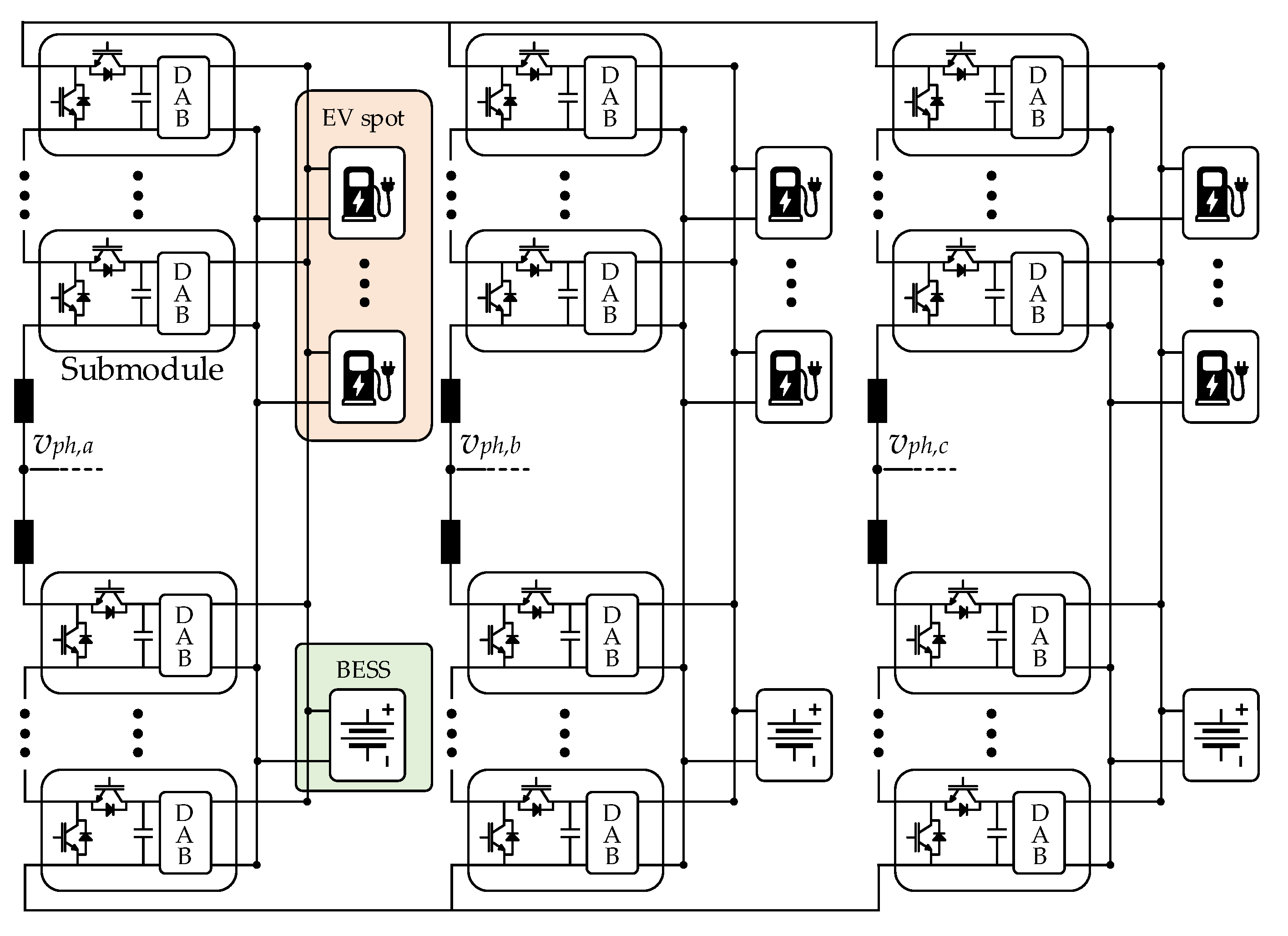
The considered charging station is equipped with 12 charging spots, 4 of each of the available dc buses. It is worth noting that the management of the communication protocols of the charging spots is out of the scope of this paper. This work focuses on defining an effective power electronic interface capable of satisfying the different load demands required by the connected electric vehicles. The public charging points can be supplied in direct or alternating current; however, a standard classification based on the available charging power is still not present. As an example, the Alternative Fuels Infrastructure Directive of the European Union only differentiates between normal (<22 kW) and fast (>22 kW) charging points, leaving the Member States the possibility of defining the criteria for distinguishing the power rating of the charging points [32]. In this regard, taking, as a reference, the Italian case, four topologies are distinguished: slow (up to 7.4 kW), quick (up to 22 kW), fast (up to 50 kW), and ultra-fast (>50 kW) [33].
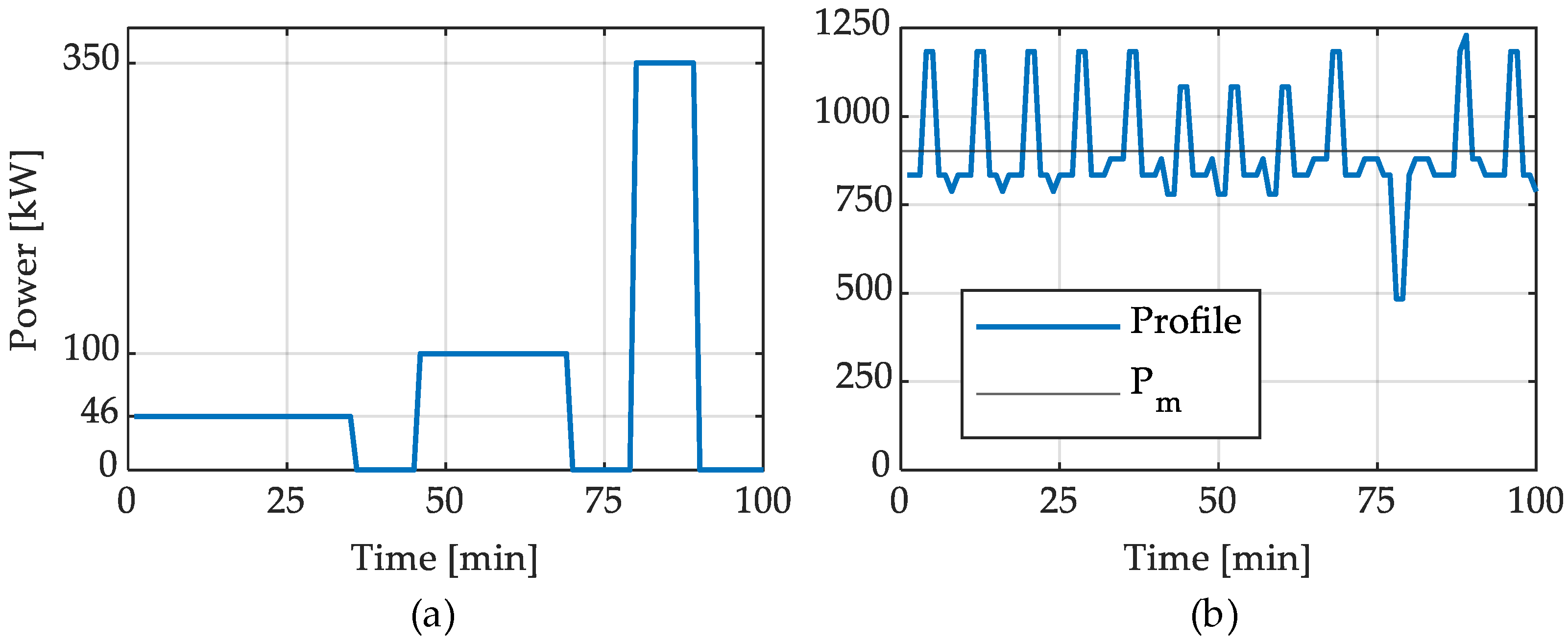
In this work, the charging spots are connected to the dc ports, and the achievable charging powers are defined as follows: the maximum charging power level of the station, i.e., ultra-fast, was set to 350 kW, while two further fast charging levels of 46 kW and 100 kW were used to create a heterogeneous power demand. Finally, the rated dc bus voltage is set to 400 V. The vehicles to be charged were selected according to the charging level mentioned above. Their main data are reported in Table 1, where charging times are calculated to charge the vehicle battery from 20% to 90% of the SOC. The single spot power profile, taken from [12], lasts Ttot = 100 min and is shown in Figure 7a. It is supposed that all 12 charging spots are working at the same time, and the power profiles of the spots are uniformly delayed one from the other, i.e., the profiles are obtained with a time shift of Ttot/12 [12]. As a consequence, the charging station profile ptot(t) is obtained by summing the power profiles of the spots and is shown in Figure 7b. In the figure, the average power of the charging demand Pm = 902.1 kW is also indicated.
The energy storage system can be sized starting from the defined profile and the power delivered by the grid pg(t). For the sake of the sizing procedure, it is possible to assume that the grid provides the average power of the profile, i.e., pg(t) = Pm. Thus, the storage energy profile es(t) can be retrieved as
e s ( t ) = p t o t ( t ) p g ( t ) d t = p t o t ( t ) P m d t .
The minimum BESS sizing energy E s min can be computed as
E s m i n = max e s ( t ) min e s ( t ) .
Nevertheless, it is always recommended to avoid full discharge of the battery. For this reason, a 30% capacity margin is considered.
In order to size the BESS, it is possible to also consider the system efficiency ηsys, and the total BESS sizing energy E s tot is obtained as
E s t o t = E s m i n 0.7 η s y s .
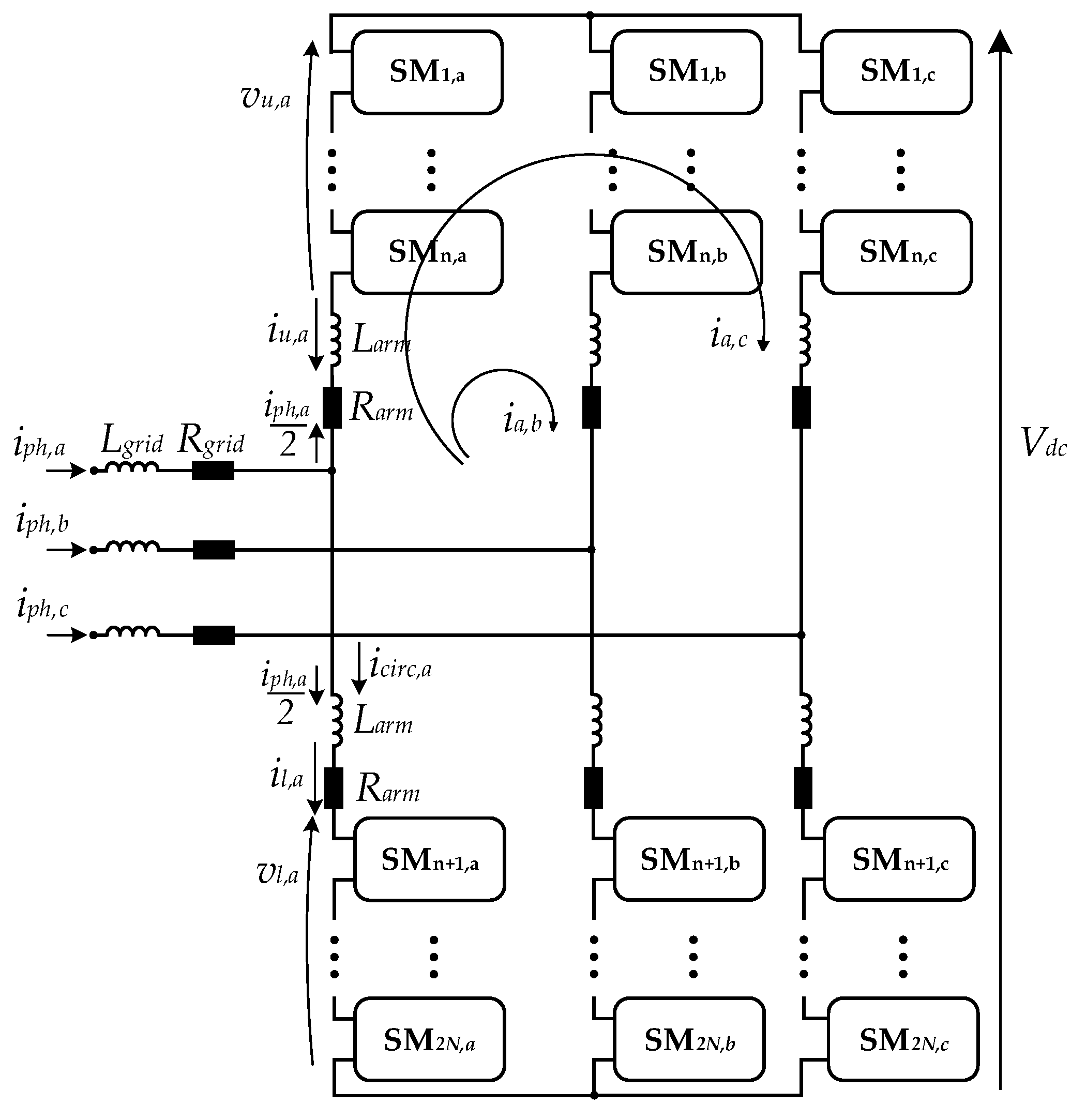
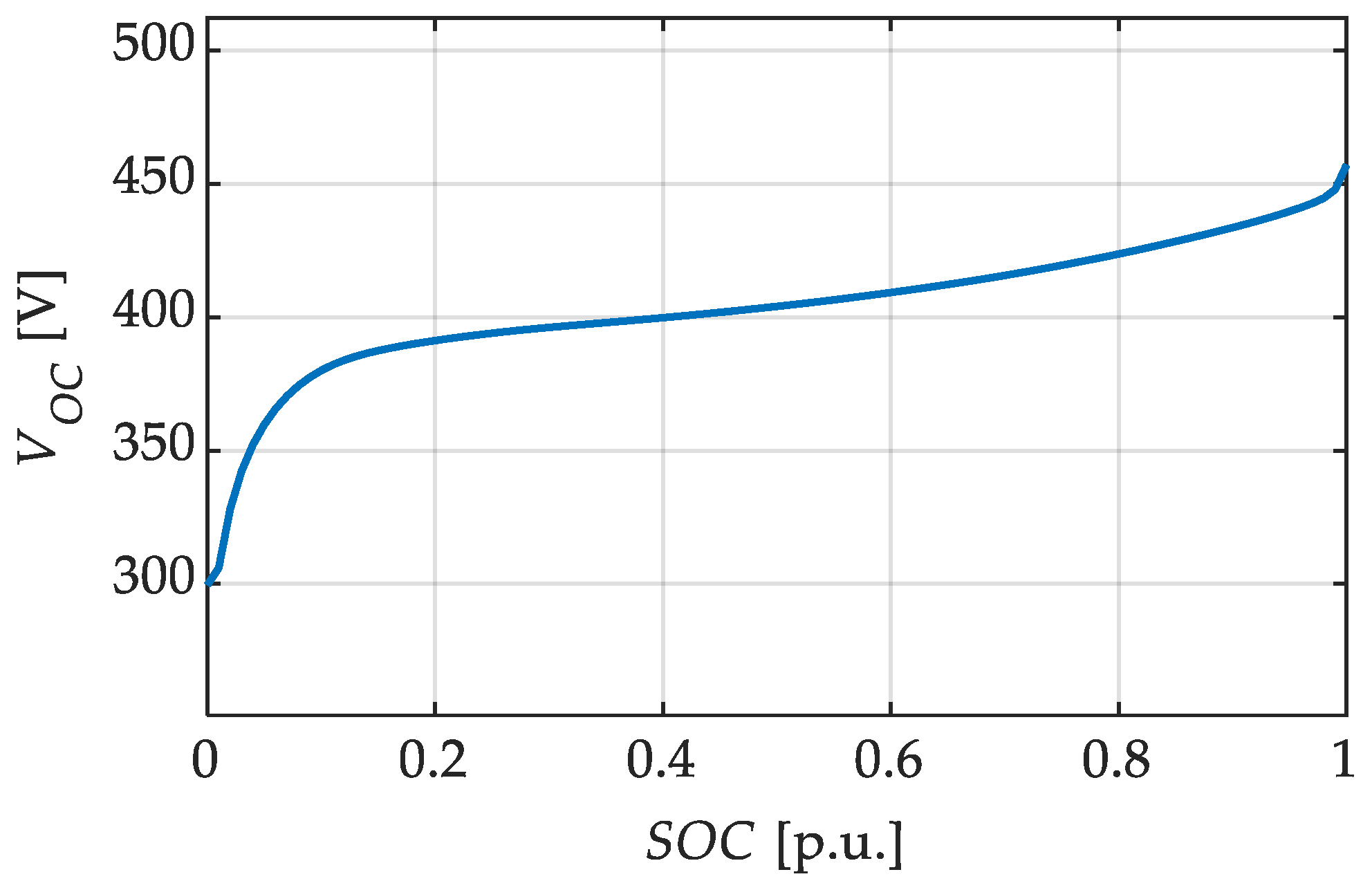
Since the storage system is split among three BESSs connected to MMC legs, each BESS is sized to have one-third of the total energy. The equivalent leg energy is indicated by Ebatt. The parameters of the BESS and of the battery pack are shown in Table 2, while the SOC-VOC characteristic considered is reported in Figure 8. For the sake of simplicity, the installed BESSs were considered equal among the converter phases. However, the results can be easily extended in the case of integrating BESSs with different voltage levels, states of health, or technologies.
It should be pointed out that since the installed BESS is responsible for proving only peak shaving, it is expected that, if correctly sized, its SOC at the end of the total power charging profile will reach the initial value. Furthermore, depending on the demanded dc bus power, differences among the three BESS SOCs may arise during the converter operation. In this case, the circulating current control will tend to equalize their SOCs, avoiding compromising the overall system. However, this is limited by the maximum circulating injectable current. In addition, it is worth noting that the total installed BESS energy depends only on the charging station power profile and the grid power. Then, it is possible to subdivide the BESS into multiple subgroups according to the system requirements. However, since the installed energy does not vary, the BESS cost remains unchanged. Instead, the BESS disposition mainly affects the management of the integrated sources, the system reliability, and the required cooling systems. The proposed charging station architecture achieves a trade-off among the previously mentioned issues. Indeed, the BESS installation is performed at the MMC leg level, achieving a certain modularity without increasing the system complexity.

3.2. Grid-Side Converter and DAFB Parameter Selection

The main parameters of the considered MV grid and of the grid-side converter are reported in Table 3 and Table 4, respectively.
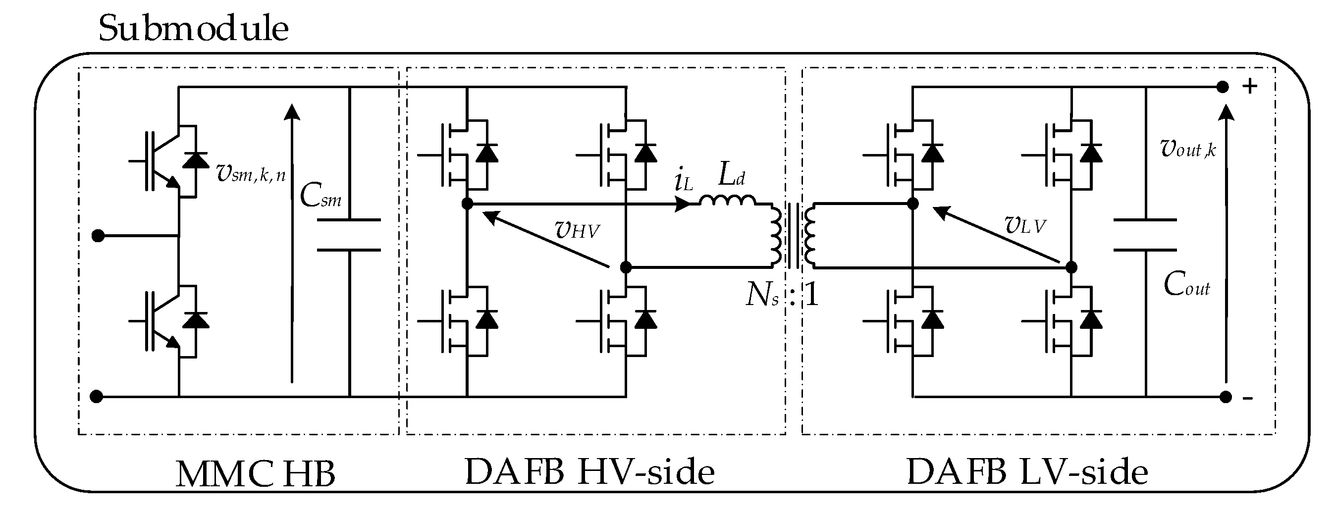
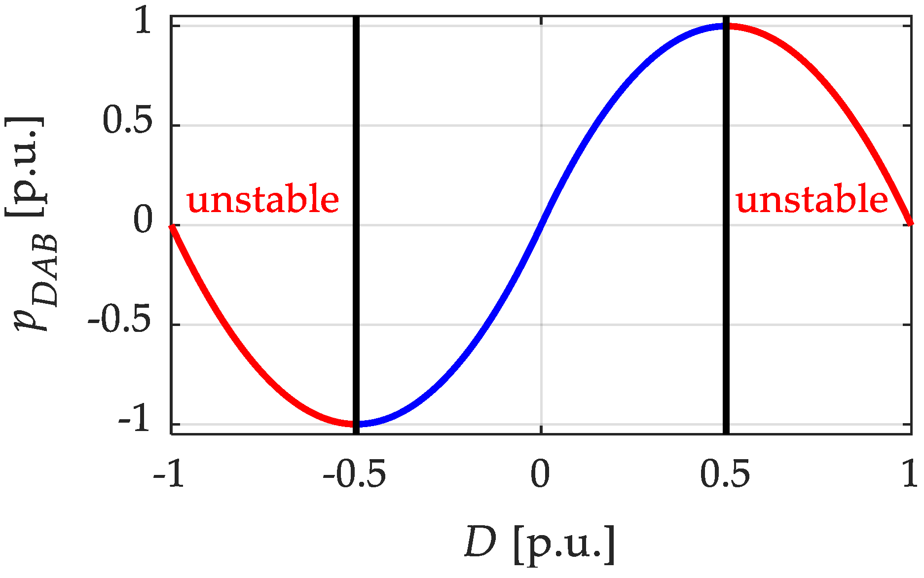
In order to ensure proper and efficient operations of the charging station, it is necessary to pay particular attention to the DAFB rating and parameter selection. Indeed, as anticipated in the previous section, ZVS operations of the converter are ensured only inside the boundaries identified in (10). To respect this relation, estimating the DAFB voltage levels and selecting the proper turns ratio Ns are necessary. As explained in Section 2, vsm is controlled to be constant (i.e., equal to Vsm), while the dc bus voltage Vbus is dependent on the battery SOC and working conditions. For this reason, by considering the open circuit battery voltage at SOC equal to 0.5, the transformer turns ratio is defined as
N s = round V s m V O C S O C = 0.5 .
In order to determine the converter-rated active power, it is necessary to consider both the grid and the balancing powers. In the considered case, the charging station can absorb a maximum power P g   max from the grid. Hence, the maximum active power entering an SM that the single DAFB has to manage is
P S M m a x = 1 2 N P g m a x 3 + P c i r c , d c m a x
where P circ , dc   max = V dc I circ , dc   max . From the obtained power values, it is possible to establish sizing parameters for the DAFB. For a fixed switching frequency fs and after having established the turns ratio Ns according to (17), it is necessary to select the converter leakage inductance, i.e., Ld, to ensure the capability of delivering the maximum requested power at the minimum dc bus voltage V bus   min . Thus, the DAFB leakage inductance, on the HV side, can be retrieved substituting in (8): D = 0.5, vout = V bus   min , and PDAB = 1 . 05 · P SM   max . In this way, the maximum requested power is delivered in every condition. Finally, the DAFB parameters defined according to the previous procedure are reported in Table 5.

3.3. Simulation Results

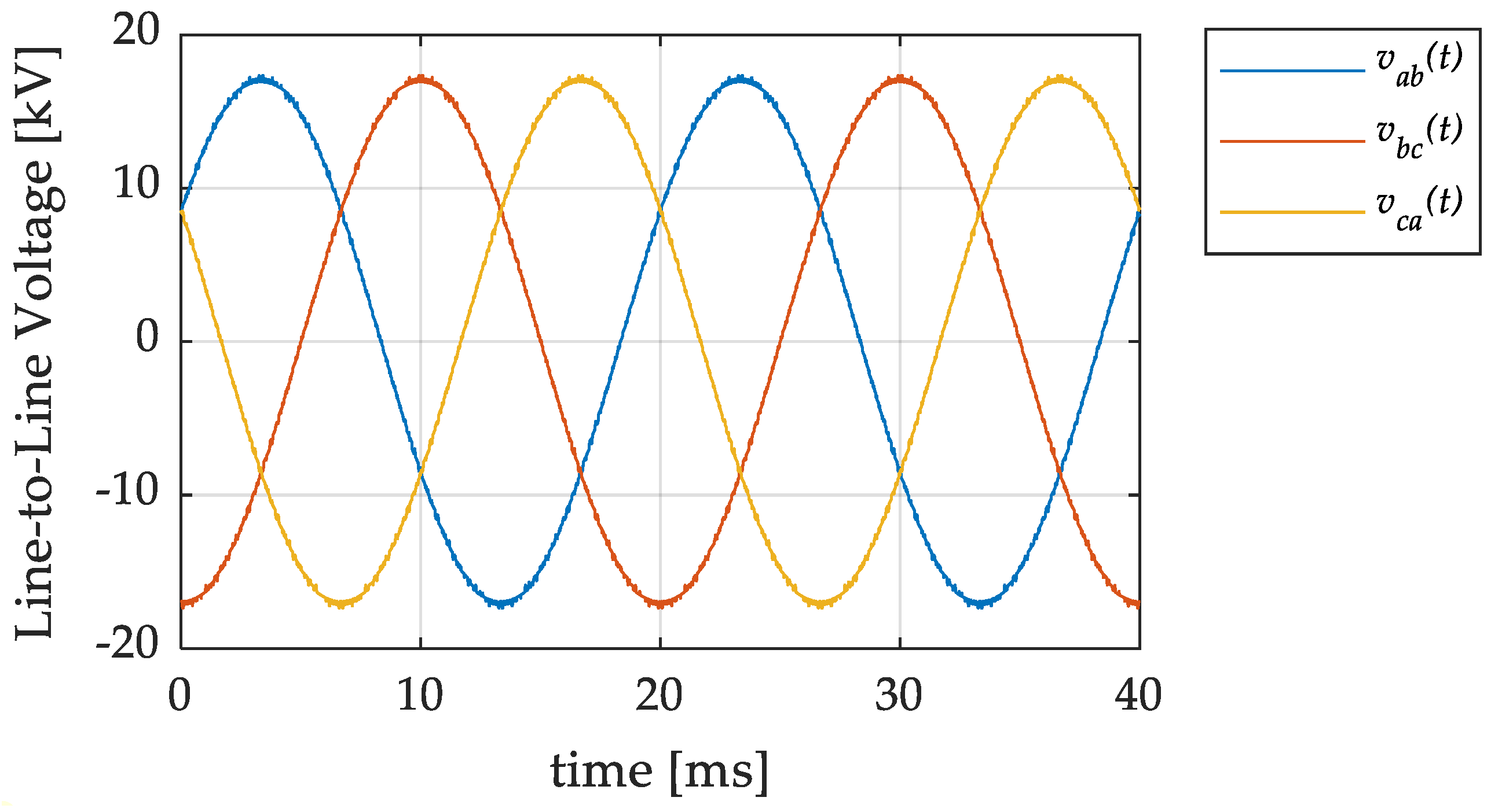
The first simulation aims to show the output voltage and current waveforms of the MMC. In this first case, the station absorbs the average power of the power profile previously defined, i.e., Pm = 902.1 kW. 
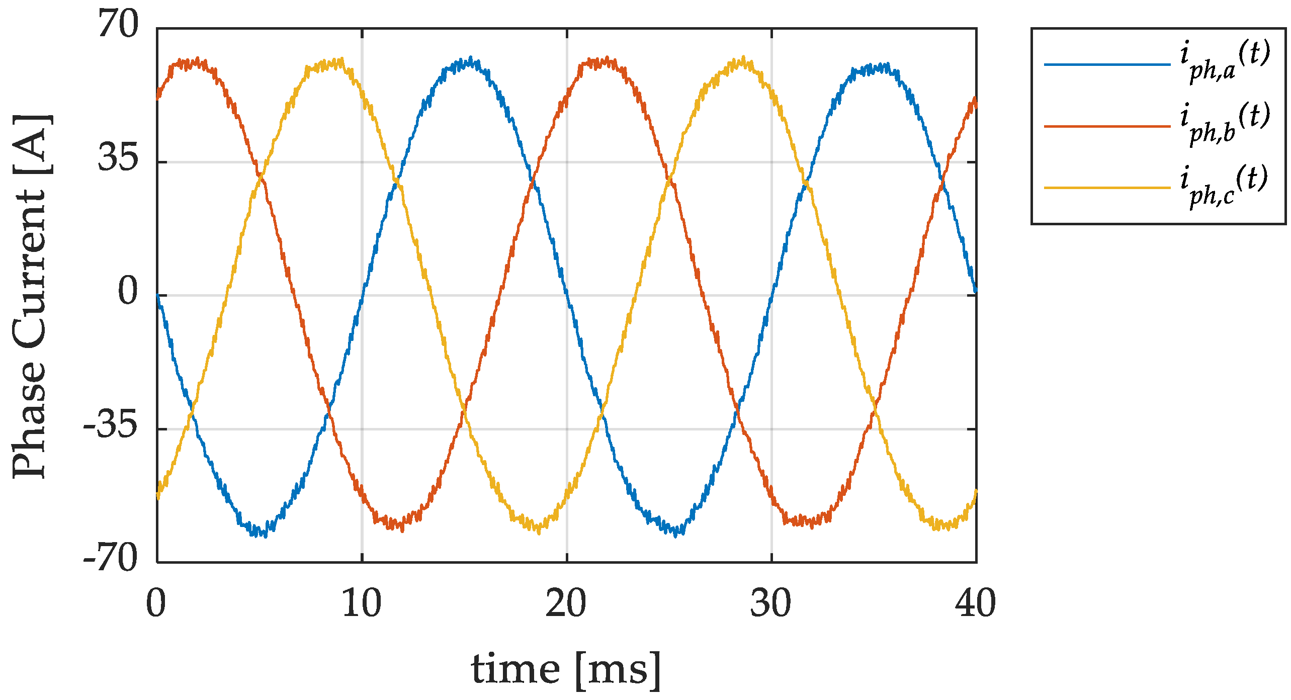
Figure 9 shows the three line-to-line voltages, while Figure 10 shows the phase currents. In order to evaluate the THD of the phase currents, it is possible to refer to the standard IEEE 519–2022, which suggests computing the THD up to the 50th harmonic [34]. For this reason, the switching frequency harmonic component is not interesting in the computation. The THDs of the phase currents are reported in Table 6. As is possible to see, the converter ensures low THD values without the need for additional filters when connected to the considered grid.
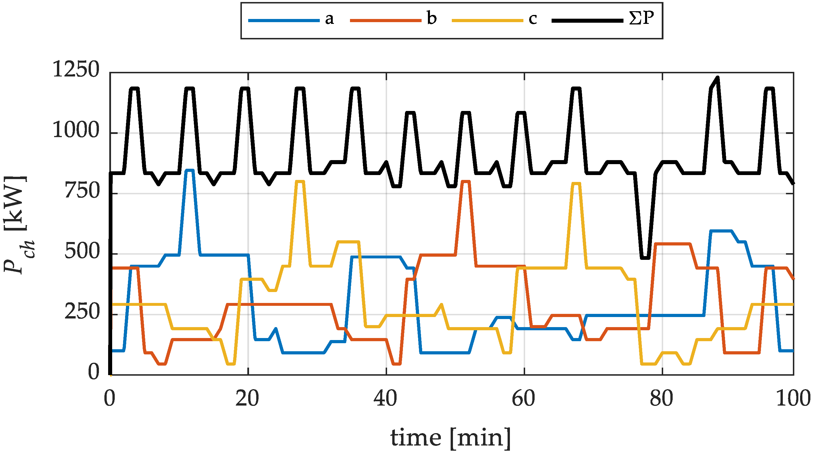
The second simulation was performed to assess the capability of the charging station to fulfil the power demand and to test its control. The initial SOCs of the three stationary batteries were assumed to be equal to 0.75. For each dc bus, four of the twelve profiles defined in Section 3.1. were summed to obtain three different power profiles. These were assigned in order to create load imbalances among the converter legs, aimed at testing the converter capability to manage imbalances through the circulating current control. The three power demands Pch,k required by the spots to the dc buses are reported in Figure 11, along with their sum to better visualize the overall power profile. Here, it is possible to observe the imposed imbalances in the power demand among the three converter dc buses, as happens, for example, around t = 10 min, where the dc bus of phase-a experiences a peak power demand while the load on the other two dc buses is low. 
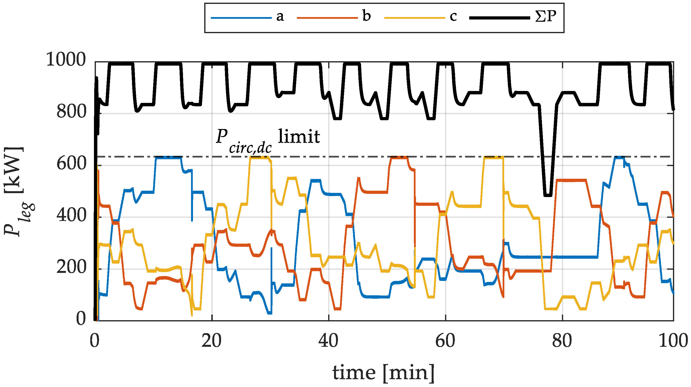
Figure 12 shows the power measured on each converter leg along with their sum, equal to the total power provided by the grid, while 
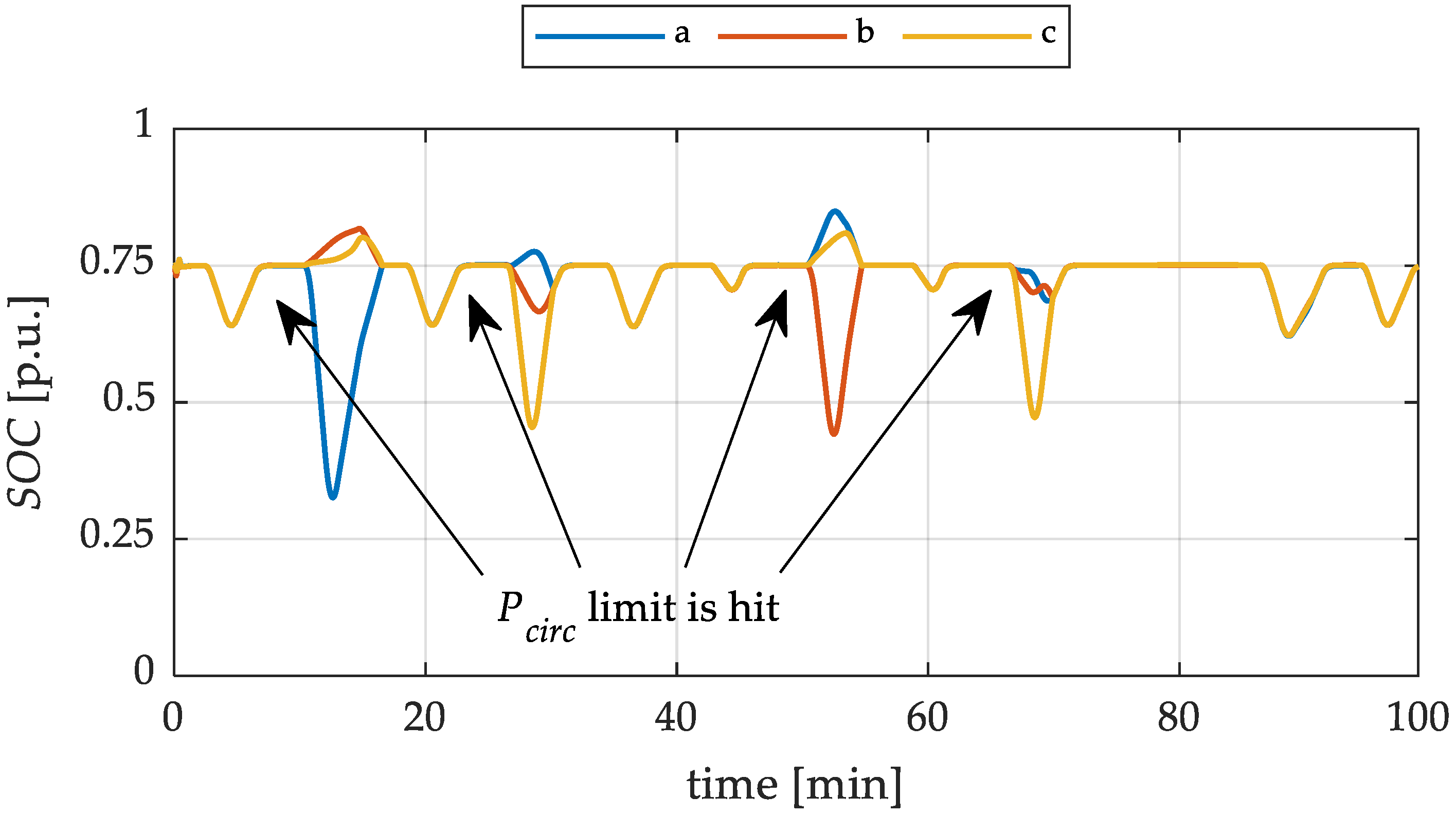
Figure 13 shows the SOC of each dc bus BESS. By comparing the previous three plots, it is possible to appreciate, from Figure 12, that the circulating current control is able to effectively move power among the converter legs according to the SOCs of the three integrated batteries and the power demanded by vehicles connected to the three charging station dc buses. In particular, when the single dc bus power demand is below the maximum power transferrable by the circulating current (which is limited at P circ , dc   max ), the leg powers tend to follow the correspondent power demand in Figure 11, and, thanks to the injection of the circulating currents, the three battery SOCs are equalized, as shown in Figure 13. Moreover, in this scenario, since the overall charging station power demand is less than the maximum power that the grid can provide, the average converter SOC is kept at 0.75 by the grid power controller. Instead, in the event of a dc bus power demand exceeding the circulating power limit, the control saturation causes the three SOCs to be unequal for short periods, while the balancing is restored once the power peak is finished, as indicated in Figure 13.
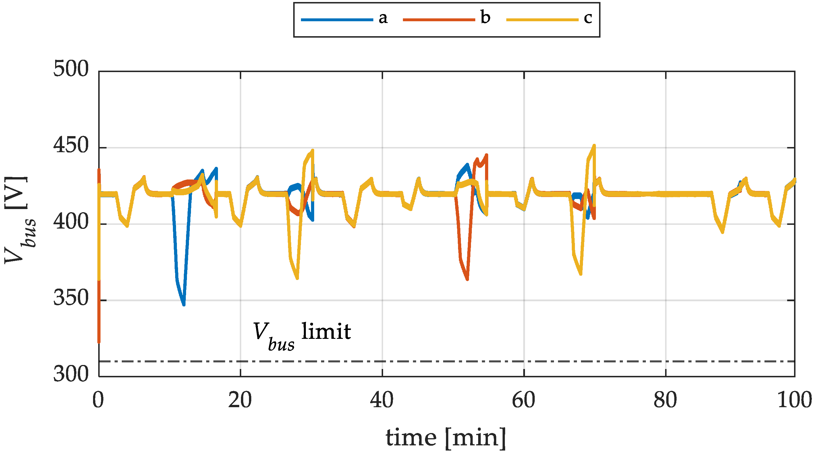
Figure 14 shows the three-leg dc bus voltages. Here, it is possible to notice that during the battery discharge, the voltage decreases due to the SOC decrease and the voltage drop in the battery internal resistance, while when the batteries are being charged, the relative voltage increases. Moreover, for each of the three dc buses, the voltage does not decrease under the minimum allowed value V bus   min = 310   V , i.e., the power demand of the vehicles is not reduced by the control, as explained in Section 2.4. Thus, the charging station is able to fulfill the power demand completely.
The front-side capacitor voltages of each SM in the upper arm of phase-a are reported in Figure 15. Here, it is shown that the average value is kept at the rated value of 1500 V from the DAFB voltage control, while the sorting algorithm guarantees the balancing of the N arm capacitors. Moreover, it is possible to observe that small-voltage overshoots arise in correspondence with sudden changes in the leg power (i.e., in the leg current), while the oscillation around the average value Vsm increases during higher-power intervals, as happens, for example, in the first 20 min, around 40 min, and at the end of the profile.
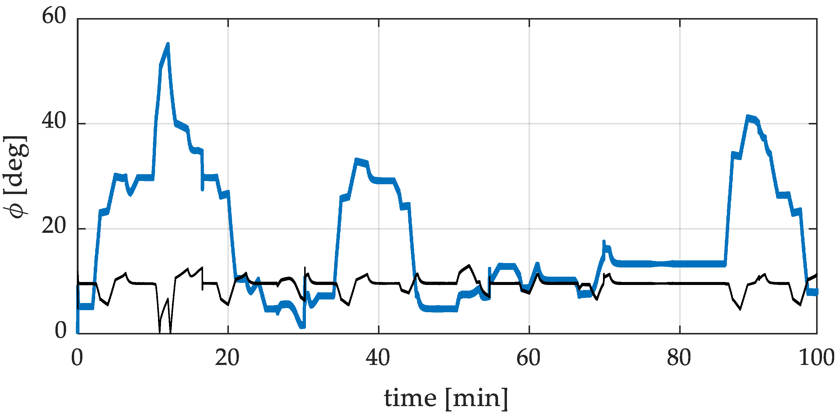
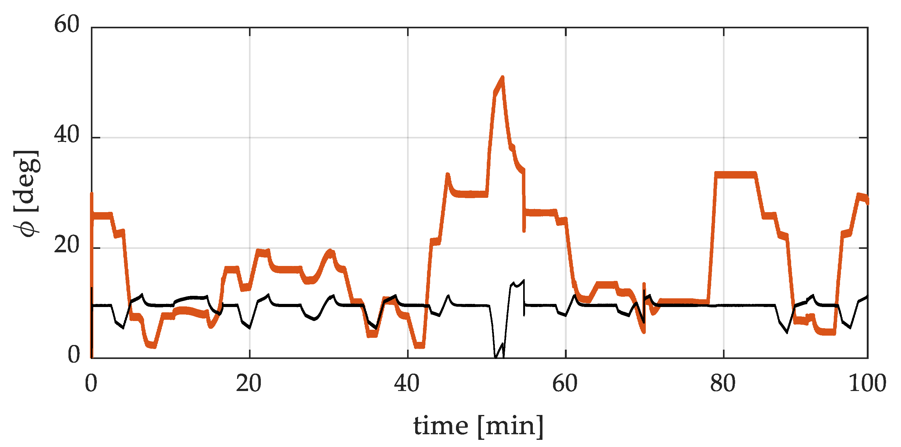
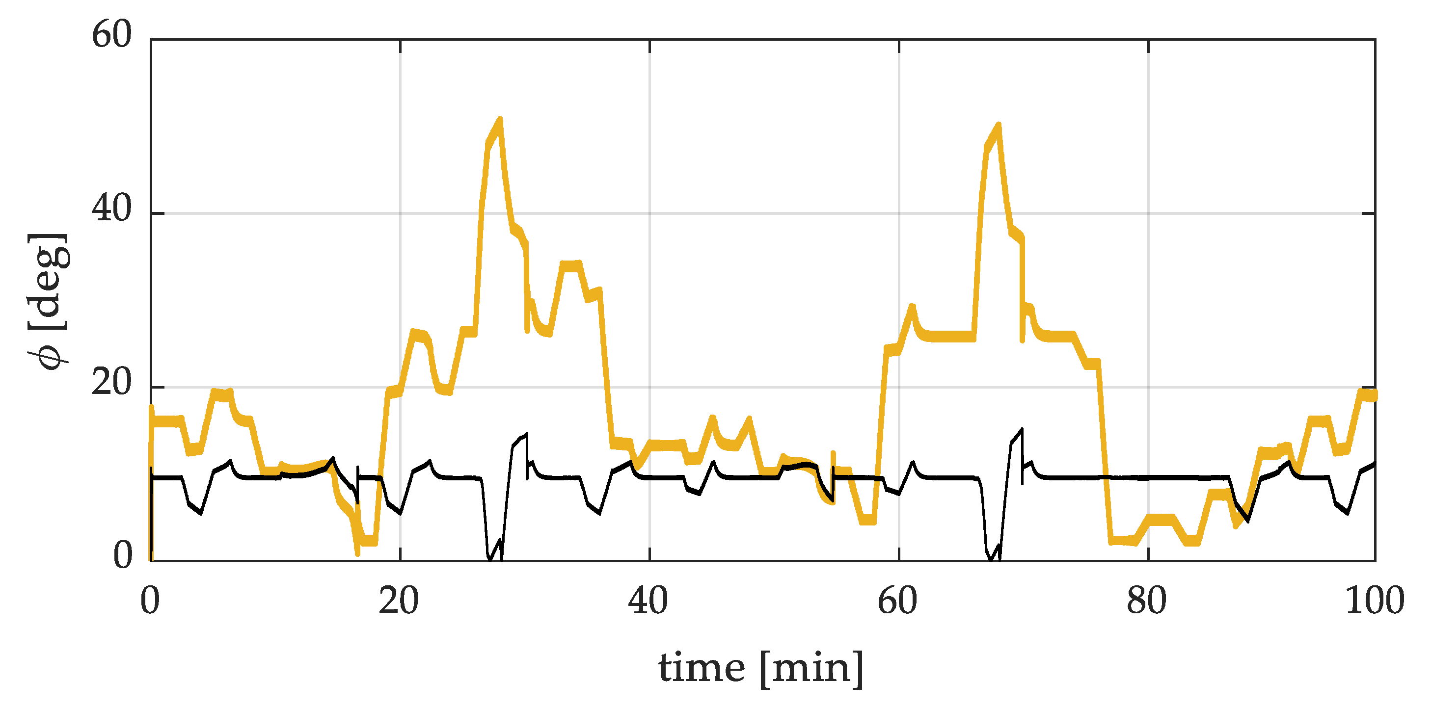
For what concerns the operation of the DAFB converters, the average DAFB control angles versus time are reported, for each phase, in Figure 16, Figure 17 and Figure 18, where the ZVS lower boundary, computed using (10) and (11), is shown in black. In particular, it is possible to observe that DAFB converters operate above the ZVS limit angle during high-power peaks, while, as expected, ZVS is not achieved for low-power demand.
Finally, operations of the DAFB were analyzed in more detail around a change in the power reference. In particular, the analysis focuses on a DAFB in the upper arm of phase-a and concerns the demand power change occurring at t = 2 min, as reported in Figure 11. The results in a time window of 0.8 s are reported in Figure 19 and Figure 20. 
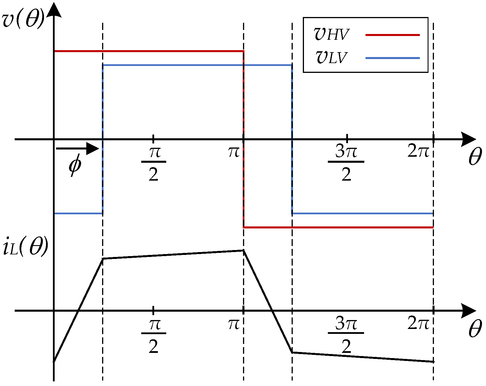
Figure 19 shows the control angle ϕ of the converter, where it is possible to observe that, in correspondence with an increase in the required power, the average control angle raises as easily deducible from (8). In particular, the increase in the average value is due to the feed-forward term in the DAFB control, while the oscillations are related to the PI-regulator output. Figure 20 shows the inductor current iL in time. The behavior of the inductor current is strictly related to the phase shift of the converter: as it increases, the current peak increases. However, its increase is not continuous with the phase shift one due to the presence of a discrete time step in the simulation, which influences the minimum phase shift detectable by the converter. The angle resolution ϕres can be computed as
ϕ r e s = 360 f s T s t e p = 0.9 °
where 
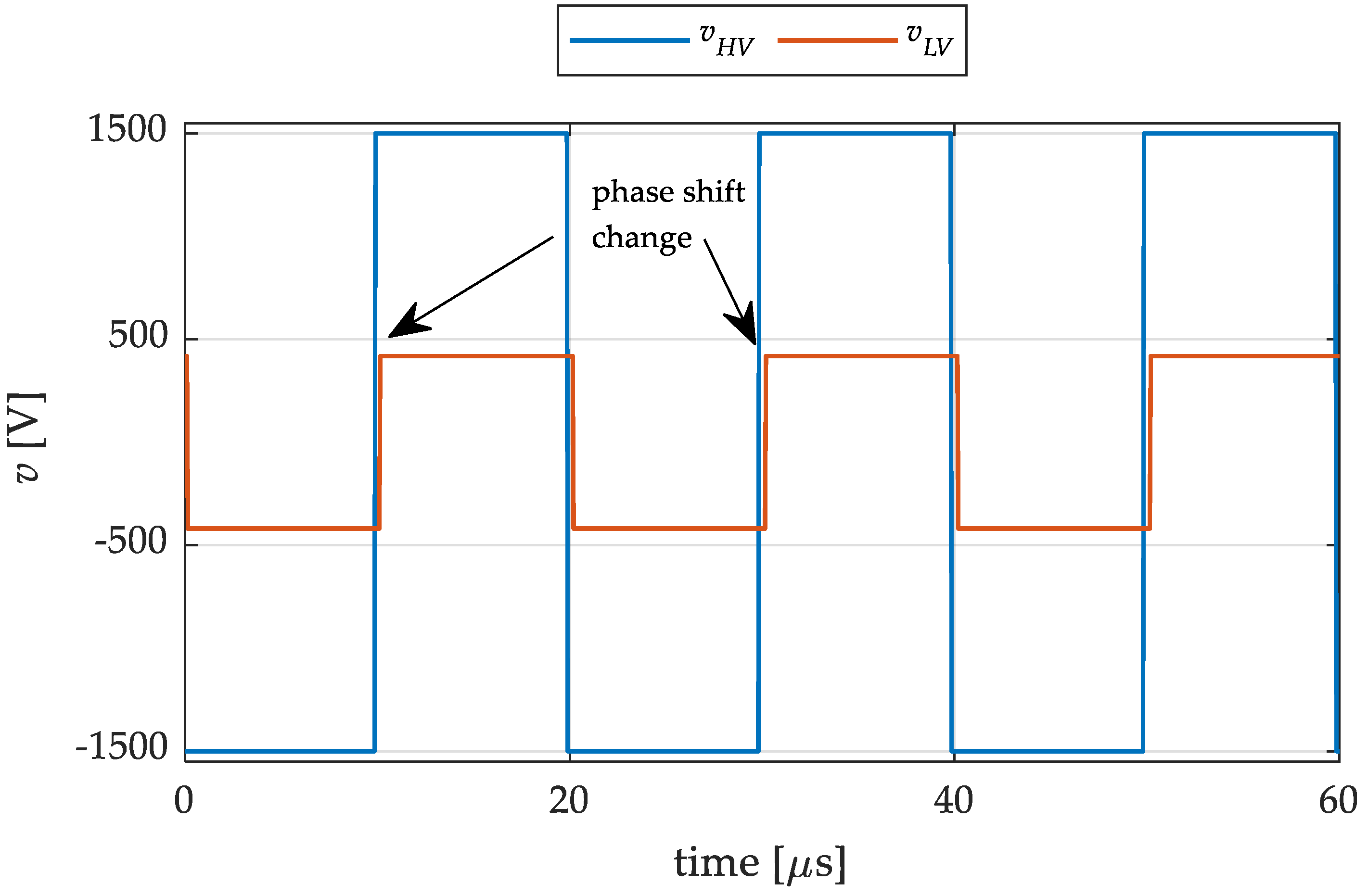
Tstep = 50 nS is the simulation time step. By analyzing a time window of 60 μs, reported in Figure 19 and Figure 20, it is possible to confirm the described behavior. In particular, this is evident by analyzing the zoom reported in the figures. From Figure 19, it is possible to appreciate that when ϕ crosses 5.4°, i.e., 6ϕres, the inductor current peak changes, while in correspondence with the next step in ϕ, the current peak is not affected since the angle difference is below the system resolution. This effect can also be visualized in Figure 21, where the two voltage square waves vHV and vLV are reported and where it is possible to observe the slight change in the phase shift between the two.

4. Discussion

The results presented in Section 3.3 show that the proposed charging station topology ensures high performances and provides a filter-less connection to the MV grid with peak-shaving capabilities thanks to the installed BESS. In the following, the results are analyzed in more detail, and some considerations on the investigated charging station topology are addressed.
First, it is possible to see, in Figure 11, Figure 12 and Figure 13, that the circulating current control is able to keep the three SOCs of the three batteries equalized when the required balancing power is below the limit. As expected, when the load imbalance among the three dc buses is high, the balancing power limit is hit, and the balancing is no longer effective. However, the SOC equalization is restored quickly once the short imbalance ends. Moreover, thanks to the grid regulator, the average SOC of the charging station is kept equal to the reference one, i.e., 0.75, when the power demand is within the maximum converter rating (depending on grid and circulating powers), while during the demand peaks, the batteries provide for peak shaving.
It is possible to notice that the power to be absorbed from the grid has to be necessarily higher than the demand average, i.e., Pm = 902.1 kW, in order to compensate for power losses in the system. In this way, the final average SOC is equal to the initial one. Since losses in the switches (i.e., due to conduction and switching) were not considered in this work, the main dissipative elements are the arm and the battery resistances. In particular, losses on the arm resistance Rarm = 2 mΩ can be considered negligible with respect to ones due to the battery resistance Rbatt = 85 mΩ.
Even if it was not addressed in this paper, the BESS size is interesting. In fact, as the charging power involved in UFC is very high, a smaller battery capacity (as the one considered here, which is the minimum one required to satisfy the demand considered) leads the battery to work at very high C rates, with repercussions on the system efficiency and the battery lifetime. For this reason, further studies may regard the selection of the optimal battery capacity, considering the aging effect and its efficiency.
Moving to the analysis of the operation of the DAFB converters, Figure 16, Figure 17 and Figure 18 show that the sizing procedure ensures ZVS during the high loading operation of the converters. In this way, the efficiency of the DAFBs and, consequently, of the charging station, is maximized. Moreover, it is shown that the maximum duty control angle reached during the simulation is around 60°, while the maximum value is 90°. The maximum angle is reached when the maximum power has to be transferred in the presence of minimum dc bus voltage (i.e., the second P DAB   max value in Table 5), a condition that never occurs in the considered case study. A possible improvement may be related to the study of the possibility of extending the ZVS region acting on both the MMC and DAFB control.
For what concerns the capacitor voltage, Figure 15 shows that the SM voltage is kept around the rated value of 1500 V thanks to the DAFB control, while the balancing between intra-arm capacitors is maintained through the sorting algorithm.
Considering the presence of circulating components, the circulating current control strategy allows for moving power among the three dc buses and equalizing the SOC of the three batteries. In this way, it is possible to manage a very imbalanced load between the three converter phases, keeping balanced absorption from the grid without the need to oversize the storage system. However, it is worth noting that the presence of the circulating current is always associated with a decrease in the converter efficiency. For this reason, the possibility of finding an optimum combination of storage capacity and circulating current limits can be studied in order to find the trade-off between balancing performance, storage sizing, and efficiency.

5. Conclusions

The paper proposes a UFC station topology based on MMC and DAFB capable of filter-less and direct MV grid connection. In particular, by adopting insulated dc-dc converters as the DAFB in the MMC submodules, for each converter leg, it is possible to obtain three different LV dc buses through the connection of their LV sides in parallel. In this way, a storage system can be easily connected and sized, and galvanic insulation is ensured. This topology allows for the adoption of batteries featuring different technologies (e.g., second-life batteries) while preserving the modularity of the charging station. Moreover, due to vehicles connected to different charging spots, power imbalances among the dc sides occur only among the three converter legs, and they can be managed through a simple control acting on the dc component of circulating currents. The latter is exploited to move power among the phases to equalize the SOCs of the distributed BESSs.
According to the internal converter power flow, the DAFB parameter selection and BESS sizing are provided. The BESS sizing procedure was performed to guarantee the demand peak shaving with the minimum amount of energy, while the DAFB sizing procedure was defined to always guarantee the maximum balancing power while ensuring ensure ZVS during the high loading operation of the converter. In this way, the efficiency of DAFBs, and consequently of the charging station, can be maximized.
The proposed charging station was validated through numerical simulations in MATLAB Simulink®, demonstrating its effectiveness.

Author Contributions

Conceptualization, M.B. and E.F.; methodology, E.F. and L.P.; software, E.F.; validation, E.F. and M.B.; formal analysis, E.F.; investigation, E.F. and L.P.; resources, L.P.; data curation, M.B., E.F. and L.P.; writing—original draft preparation, E.F.; writing—review and editing, M.B. and L.P.; visualization, E.F. and L.P.; supervision, L.P.; project administration, L.P.; funding acquisition, L.P. All authors have read and agreed to the published version of the manuscript.

Funding

This research received no external funding.

Data Availability Statement

Not applicable.

Conflicts of Interest

The authors declare no conflict of interest.

References

  1. Anegawa, T. Development of Quick Charging System for Electric Vehicle. In Proceedings of the 21st World Energy Congress (WEC) 2010, Montreal, Canada, 12–16 September 2010. [Google Scholar]
  2. Wang, L.; Qin, Z.; Slangen, T.; Bauer, P.; van Wijk, T. Grid Impact of Electric Vehicle Fast Charging Stations: Trends, Standards, Issues and Mitigation Measures—An Overview. IEEE Open J. Power Electron. 2021, 2, 56–74. [Google Scholar] [CrossRef]
  3. Rahman, M.M.; Oni, A.O.; Gemechu, E.; Kumar, A. Assessment of Energy Storage Technologies: A Review. Energy Convers. Manag. 2020, 223, 113295. [Google Scholar] [CrossRef]
  4. Hõimoja, H.; Vasiladiotis, M.; Rufer, A. Power Interfaces and Storage Selection for an Ultrafast EV Charging Station. In Proceedings of the 6th IET International Conference on Power Electronics, Machines and Drives (PEMD 2012), Bristol, UK, 27–29 March 2012. [Google Scholar] [CrossRef]
  5. Srdic, S.; Lukic, S. Toward Extreme Fast Charging: Challenges and Opportunities in Directly Connecting to Medium-Voltage Line. IEEE Electrif. Mag. 2019, 7, 22–31. [Google Scholar] [CrossRef]
  6. Vasiladiotis, M.; Rufer, A. Analysis and Control of Modular Multilevel Converters with Integrated Battery Energy Storage. IEEE Trans. Power Electron. 2015, 30, 163–175. [Google Scholar] [CrossRef]
  7. Vasiladiotis, M.; Rufer, A. Balancing Control Actions for Cascaded H-Bridge Converters with Integrated Battery Energy Storage. In Proceedings of the 15th European Conference on Power Electronics and Applications, EPE, Lille, France, 2–6 September 2013. [Google Scholar] [CrossRef]
  8. Liang, G.; Tafti, H.D.; Farivar, G.G.; Pou, J.; Townsend, C.D.; Konstantinou, G.; Ceballos, S. Analytical Derivation of Intersubmodule Active Power Disparity Limits in Modular Multilevel Converter-Based Battery Energy Storage Systems. IEEE Trans. Power Electron. 2021, 36, 2864–2874. [Google Scholar] [CrossRef]
  9. Vasiladiotis, M.; Rufer, A. A Modular Multiport Power Electronic Transformer with Integrated Split Battery Energy Storage for Versatile Ultrafast EV Charging Stations. IEEE Trans. Ind. Electron. 2015, 62, 3213–3222. [Google Scholar] [CrossRef]
  10. Vasiladiotis, M.; Bahrani, B.; Burger, N.; Rufer, A. Modular Converter Architecture for Medium Voltage Ultra Fast EV Charging Stations: Dual Half-Bridge-Based Isolation Stage. In Proceedings of the International Power Electronics Conference, IPEC-Hiroshima—ECCE Asia, Hiroshima, Japan, 18–21 May 2014; pp. 1386–1393. [Google Scholar] [CrossRef]
  11. Vasiladiotis, M.; Rufer, A.; Beguin, A. Modular Converter Architecture for Medium Voltage Ultra Fast EV Charging Stations: Global System Considerations. In Proceedings of the 2012 IEEE International Electric Vehicle Conference, Greenville, SC, USA, 4–8 March 2012; pp. 1–7. [Google Scholar]
  12. Barresi, M.; Ferri, E.; Piegari, L. An MMC-Based Fully Modular Ultra-Fast Charging Station Integrating a Battery Energy Storage System. In Proceedings of the 16th International Conference on Compatibility, Power Electronics and Power Engineering (CPE-POWERENG), Birmingham, UK, 29 June–1 July 2022. [Google Scholar]
  13. Pugliese, S.; Buticchi, G.; Mastromauro, R.A.; Andresen, M.; Liserre, M.; Stasi, S. Soft-Start Procedure for a Three-Stage Smart Transformer Based on Dual-Active Bridge and Cascaded H-Bridge Converters. IEEE Trans. Power Electron. 2020, 35, 11039–11052. [Google Scholar] [CrossRef]
  14. Wang, D.; Tian, J.; Mao, C.; Lu, J.; Duan, Y.; Qiu, J.; Cai, H. A 10-KV/400-V 500-KVA Electronic Power Transformer. IEEE Trans. Ind. Electron. 2016, 63, 6653–6663. [Google Scholar] [CrossRef]
  15. Ouyang, S.; Liu, J.; Chen, H. Arm Current Stress Reduction Technique for a Delta-Connected Solid State Transformer Using Zero-Sequence Current Injection. IEEE Trans. Power Electron. 2021, 36, 12234–12250. [Google Scholar] [CrossRef]
  16. Valedsaravi, S.; El Aroudi, A.; Martínez-Salamero, L. Review of Solid-State Transformer Applications on Electric Vehicle DC Ultra-Fast Charging Station. Energies 2022, 15, 5602. [Google Scholar] [CrossRef]
  17. Nair, A.C.; Fernandes, B.G. A Solid State Transformer Based Fast Charging Station for All Categories of Electric Vehicles. In Proceedings of the IECON 2018—44th Annual Conference of the IEEE Industrial Electronics Society, Washington, DC, USA, 21–23 October 2018; pp. 1989–1994. [Google Scholar] [CrossRef]
  18. Ramya, G.; Ramaprabha, R. Design Methodology of P-Res Controllers with Harmonic Compensation Technique for Modular Multilevel Converter Fed from Partially Shaded PV Array. In Proceedings of the International Conference on Power Electronics and Drive Systems, Sydney, NSW, Australia, 9–12 June 2015; pp. 330–335. [Google Scholar] [CrossRef]
  19. Nasri, S.; Nowdeh, S.A.; Davoudkhani, I.F.; Moghaddam, M.J.H.; Kalam, A.; Shahrokhi, S.; Zand, M. Maximum power point tracking of photovoltaic renewable energy system using a new method based on turbulent flow of water-based optimization (TFWO) under partial shading conditions. In Fundamentals and Innovations in Solar Energy; Springer: Berlin/Heidelberg, Germany, 2021; pp. 285–310. [Google Scholar]
  20. Soong, T.; Lehn, P.W. Internal Power Flow of a Modular Multilevel Converter with Distributed Energy Resources. IEEE J. Emerg. Sel. Top. Power Electron. 2014, 2, 1127–1138. [Google Scholar] [CrossRef]
  21. Prieto-Araujo, E.; Junyent-Ferré, A.; Collados-Rodríguez, C.; Clariana-Colet, G.; Gomis-Bellmunt, O. Control Design of Modular Multilevel Converters in Normal and AC Fault Conditions for HVDC Grids. Electr. Power Syst. Res. 2017, 152, 424–437. [Google Scholar] [CrossRef]
  22. Debnath, S.; Qin, J.; Bahrani, B.; Saeedifard, M.; Barbosa, P. Operation, Control, and Applications of the Modular Multilevel Converter: A Review. IEEE Trans. Power Electron. 2015, 30, 37–53. [Google Scholar] [CrossRef]
  23. Akagi, H.; Kanazawa, Y.; Koetsu Fujita, A.N. Generalized Theory of Instantaneous Reactive Power and Its Application. Electr. Eng. Jpn. 1983, 103, 58–66. [Google Scholar] [CrossRef]
  24. Lesnicar, A.; Marquardt, R. An Innovative Modular Multilevel Converter Topology Suitable for a Wide Power Range. In Proceedings of the 2003 IEEE Bologna PowerTech Conference Proceedings, Bologna, Italy, 23–26 June 2003; Volume 3, pp. 6–11. [Google Scholar] [CrossRef]
  25. De Doncker, R.W.A.A.; Divan, D.M.; Kheraluwala, M.H. A Three-Phase Soft-Switched High-Power-Density DC/DC Converter for High-Power Applications. IEEE Trans. Ind. Appl. 1991, 27, 63–73. [Google Scholar] [CrossRef]
  26. Garcia-Bediaga, A.; Villar, I.; Rujas, A.; Mir, L. DAB Modulation Schema with Extended ZVS Region for Applications with Wide Input/Output Voltage. IET Power Electron. 2018, 11, 2109–2116. [Google Scholar] [CrossRef]
  27. Kheraluwala, M.H.; Gascoigne, R.W.; Divan, D.M.; Baumann, E.D. Performance Characterization of a High-Power Dual Active Bridge Dc-to-Dc Converter. IEEE Trans. Ind. Appl. 1992, 28, 1294–1301. [Google Scholar] [CrossRef]
  28. Arias, M.B.; Bae, S. Electric Vehicle Charging Demand Forecasting Model Based on Big Data Technologies. Appl. Energy 2016, 183, 327–339. [Google Scholar] [CrossRef]
  29. Li, Y.; He, S.; Li, Y.; Member, S. Probabilistic Charging Power Forecast of EVCS: Reinforcement Learning Assisted Deep Learning Approach. IEEE Trans. Intell. Veh. 2023, 8, 344–357. [Google Scholar] [CrossRef]
  30. Ahmadi-Nezamabad, H.; Zand, M.; Alizadeh, A.; Vosoogh, M.; Nojavan, S. Multi-Objective Optimization Based Robust Scheduling of Electric Vehicles Aggregator. Sustain. Cities Soc. 2019, 47, 101494. [Google Scholar] [CrossRef]
  31. Nasab, M.A.; Zand, M.; Padmanaban, S.; Dragicevic, T.; Khan, B. Simultaneous Long-Term Planning of Flexible Electric Vehicle Photovoltaic Charging Stations in Terms of Load Response and Technical and Economic Indicators. World Electr. Veh. J. 2021, 12, 190. [Google Scholar] [CrossRef]
  32. Directive 2014/94/EU of the European Parliament and of the Council of 22 October 2014 on the Deployment of Alternative Fuels Infrastructure Text with EEA Relevance. Available online: https://eur-lex.europa.eu/legal-content/EN/TXT/?uri=celex%3A32014L0094 (accessed on 21 April 2023).
  33. ARERA Rapporto Finale Della Ricognizione-Mercato e Caratteristiche Dei Dispositivi Di Ricarica per Veicoli Elettrici. Available online: https://www.arera.it/allegati/pubblicazioni/210503_dispositivi_ricarica.pdf (accessed on 21 April 2023).
  34. 519-2022; IEEE Standard for Harmonic Control in Electric Power Systems 2022. Institute of Electrical and Electronics Engineers: Piscataway, NJ, USA, 2022.
Figure 1. Proposed charging station topology.
Energies 16 03960 g001
Figure 2. Submodule configuration.
Energies 16 03960 g002
Figure 3. MMC converter equivalent circuit.
Energies 16 03960 g003
Figure 4. Qualitative DAFB voltage and current waveforms.
Energies 16 03960 g004
Figure 5. Instability region of the power-phase shift DAFB characteristic. The unstable regions are highlighted in red.
Energies 16 03960 g005
Figure 6. Charging station control diagram.
Energies 16 03960 g006
Figure 7. Power profiles. (a) Single spot profile; (b) charging station total profile.
Energies 16 03960 g007
Figure 8. SOC-VOC curve of the considered battery.
Energies 16 03960 g008
Figure 9. Line-to-line voltage waveforms at the PCC.
Energies 16 03960 g009
Figure 10. Phase current waveforms.
Energies 16 03960 g010
Figure 11. Vehicle charging power of each dc bus and total load power.
Energies 16 03960 g011
Figure 12. Leg-measured power and total grid contribution.
Energies 16 03960 g012
Figure 13. SOC of batteries connected to each LV dc bus.
Energies 16 03960 g013
Figure 14. Voltage of each LV dc bus.
Energies 16 03960 g014
Figure 15. SM capacitor voltages for the phase-a upper arm.
Energies 16 03960 g015
Figure 16. DAFB control angle ϕ and ZVS angle limit (black line) for DAB connected on leg a.
Energies 16 03960 g016
Figure 17. DAFB control angle ϕ and ZVS angle limit (black line) for DAB connected on leg b.
Energies 16 03960 g017
Figure 18. DAFB control angle ϕ and ZVS angle limit (black line) for DAB connected on leg c.
Energies 16 03960 g018
Figure 19. DAFB control angle during a change in the power reference.
Energies 16 03960 g019
Figure 20. Inductor current waveform during a change in the power reference.
Energies 16 03960 g020
Figure 21. High- and low-voltage side voltage square wave of the DAB during a change in power reference.
Energies 16 03960 g021
Table 1. Selected vehicle data.
VehicleCharging PowerBattery CapacityCharging Time
BMW i346 kW37.9 kWh35 min
Nissan Leaf e+100 kW56 kWh24 min
Porsche Taycan350 kW83.7 kWh10 min
Table 2. Converter BESS parameters.
ParameterValueUnit
Minimum BESS energy E s min 28kWh
System efficiency ηsys0.9-
Total BESS energy E s tot 45kWh
Single battery energy Ebatt15kWh
Nominal voltage Vbatt 400V
Internal resistance Rbatt85
Table 3. Grid parameters.
ParameterValueUnit
Grid short-circuit power190MVA
Grid line-to-line voltage Vg11kV
Grid frequency fg50Hz
Grid inductance Lg2mH
Grid resistance Rg0.113Ω
Table 4. MMC parameters.
ParameterValueUnit
MMC rated active power P g   max 1MW
Rated SM voltage Vsm1500V
Number of SMs per arm N15-
Rated dc bus voltage Vdc22.5kV
SM capacitance Csm20mF
Arm inductance Larm5mH
Arm resistance Rarm1
Switching frequency fs,MMC3150Hz
Maximum circulating power per leg P circ , dc   max 300kW
Maximum circulating current I circ , dc   max 13.33A
Table 5. DAFB parameters.
ParameterValueUnit
Rated output voltage Vout400V
Minimum dc bus voltage V bus   min 310V
Transformer turn-ratio Ns4-
Switching frequency fs50kHz
Maximum grid power contribution per SM11.1kW
Maximum circulating power per SM10kW
DAB rated power PDAB22.15kW
HV-side leakage inductance Ld210μH
Maximum output power P DAB   max (@D = 0.5)28.6 1kW
22.15 2kW
Output capacitance Cout0.65mF
1 @ Vbus = Vout. 2 @ Vbus =   V bus   min .
Table 6. Phase current THD values.
CurrentTHD [%]
iph,a1.44
iph,b1.41
iph,c1.48
Disclaimer/Publisher’s Note: The statements, opinions and data contained in all publications are solely those of the individual author(s) and contributor(s) and not of MDPI and/or the editor(s). MDPI and/or the editor(s) disclaim responsibility for any injury to people or property resulting from any ideas, methods, instructions or products referred to in the content.

